


HMI 575
GOLDEN SCAN 3
ENGLISH
HMI 575
HMI 1200
HMI 1200 TV
®
1
ENGLISH
• Installation
Make sure all the parts for fixing the projector are in a good state of repair.
Make sure the point of anchorage is stable before positioning the projector.
The safety rope, properly hooked onto the fitting and secured to the framework, must
be installed so that, if the primary support system fails, the fitting falls as little as
possible. If the safety rope gets used, it needs to be replaced with a genuine spare.
SAFETY INFORMATION
1
INSTRUCTIONS MANUAL
Carefully read this instructions manual in its entirety and keep it safe for future
reference.
It is essential to know the information and comply with the instructions given
in this manual in order to ensure the fitting is installed, used and serviced
correctly and safely.
CLAY PAKY S.p.A. disclaims all liability for damage to the fitting or to other
property or persons deriving from installation, use and maintenance that have
not been carried out in conformity with this instructions manual, which must
always accompany the fitting.
CLAY PAKY S.p.A. reserves the right to modify the characteristics stated in
this instructions manual at any time and without prior notice.
Congratulations on choosing a Clay Paky product! We thank you for your
custom. Please note that this product, as all the others in the rich Clay Paky
range, has been designed and made with total quality to ensure excellent
performance and best meet your expectations and requirements.
• Maximum ambient temperature
For the fitting to operate well and reliably, the ambient temperature should not
exceed 35°C (95°F).
• IP20 protection rating
The fitting is protected against penetration by solid bodies of over 12mm (0.5”) in
diameter (first digit 2), but not against dripping water, rain, splashes or jets of water
(second digit 0).
• Protection against electrical shock
This fitting is classified in accordance with the type of protection against electrical
shock, in Class I. It must therefore be connected to a power supply system with
efficient earthing.
It is however recommended to protect the supply lines of the projectors from indirect
contact and/or shorting to earth by using appropriately sized residual current
devices.
• Connecting to the supply mains
Connection to the electricity mains must be carried out by a qualified electrical
installer.
Check that the mains frequency and voltage correspond to the frequency and
voltage stated on the electrical data label for which the projector is designed.
This label also gives the input power. Refer to this to evaluate the maximum number
of fittings to connect to the electricity supply in order to avoid overloading.
• Maintenance
Before starting any maintenance work or cleaning the projector, cut off power from
the mains supply.
After switching off, do not remove any parts of the fitting for 10 minutes.
After this time the likelihood of the lamp exploding is virtually null. If it is necessary to
replace the lamp, wait for another 15 minutes to avoid getting burnt.
The fitting is designed to hold in any splinters produced by a lamp exploding.
The lenses must be fitted and, if visibly damaged, they have to be replaced with
genuine spares.
• Temperature of the external surface
The maximum temperature that can be reached on the external surface of the fitting,
in a thermally steady state, is 90°C (194°F).
• Lamp
The projector mounts a high-pressure lamp that needs an external igniter.
This igniter is fitted onto the projector.
- Carefully read the "operating instructions" provided by the lamp manufacturer.
- Immediately replace the lamp if damaged or deformed by heat.
It is permissible to mount the fitting on normally flammable surfaces.
The products referred to in this manual conform to the
European Community Directives to which they are subject:
• Low Voltage 73/23
• Electromagnetic Compatibility 89/336
HMI 1200
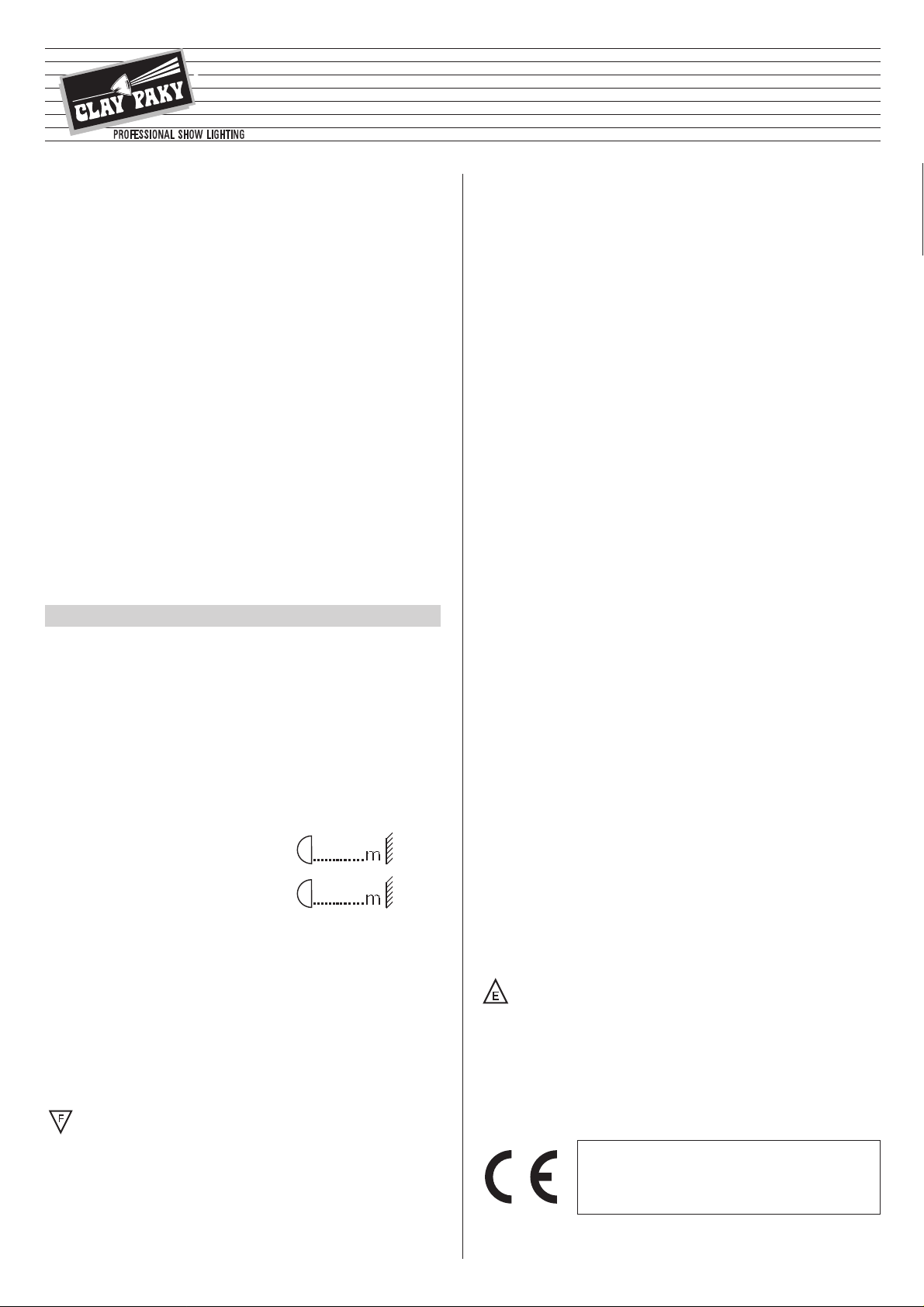
• Minimum distance from target objects
The projector must be positioned in such a way
that objects struck by the beam are separated
from the lens at least by the distance indicated
on the lamp change label against the symbol
shown alongside.
• Minimum distance of flammable materials
The projector must be positioned so that any flammable materials are at least
0,1 meter (4”) for HMI 1200 and 0,07 meter (3”) for HMI 575 from every point on the
surface of the fitting.
(8’ 2’’)
2.5 m
HMI 575
(5’ 11’’)
1.8 m
• Preparing the warning label
Find the warning label (19) on the re-lamping cover (18) and, if necessary, replace it
with one of the optional multilingual labels (16) located in the projector lamp
compartment. For the instructions on opening the projector, read paragraph
4 MAINTENANCE.
CAUTION: Read carefully and meticulously apply the information and
instructions given on this label. In addition, check it is never removed as it
contains important safety information.
• Fitting the lamp
Refer to the instructions for opening the projector and changing the lamp in
paragraph 4 MAINTENANCE.
2
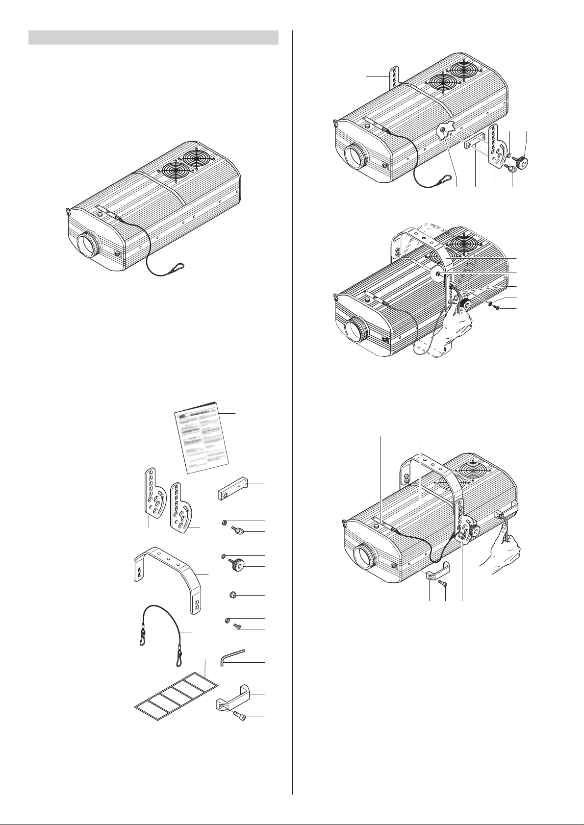
• Packing contents
Besides the projector, the packing also contains the following accessories:
- This instructions manual
code 099406 (1).
-
2 spacers code
167002/001 (2).
- 1 right bracket support plate
code 167003/001 (3).
- 1 left bracket support plate
code 167003/002 (4).
- 2 eyebolts M8x20mm
code 167004/001 (5).
-
2 nuts M8
code 020106/006 (6).
- 2 knobs code 020502 (7).
- 2 plane washers ø10,5mm
code 020210/004 (8).
-
1 bracket
code 101011/001 (9).
- 4 bracket bushings
code 101014/001 (10).
- 4 countersunk washers
code 080606/001 (11).
- 4 countersunk head
screws M8x20mm
code 020005/001 (12).
- 1 Allen wrench 5 mm
code 050001 (13).
- 4 handles
code 082017/001 (14)
(only for TV version).
- 8 screws TCEI M8x20
code 020002/029 (15).
- Multilingual label (16) with
safety information code 081948/003
(located in the projector lampholder compartment).
- 1 safety ropes code 105041/001 (17).
• Fitting the bracket
• Fitting the handles (only for TV version)
2
13
14
15
12
1
4
3
5
6
7
8
9
10
11
17
16
7
6 2 4 5
8
3
12
11
9
10
13
1514 4
19 18
UNPACKING AND PREPARING
2
• Unpacking
Open the box from the top, take all the accessories out of the box and remove the
polystyrene containing structures.
Open the plastic bag, remove the projector from the box frame and position it on a
horizontal top where access is easy to carry out the following preliminary work.
3
5
17
5
17
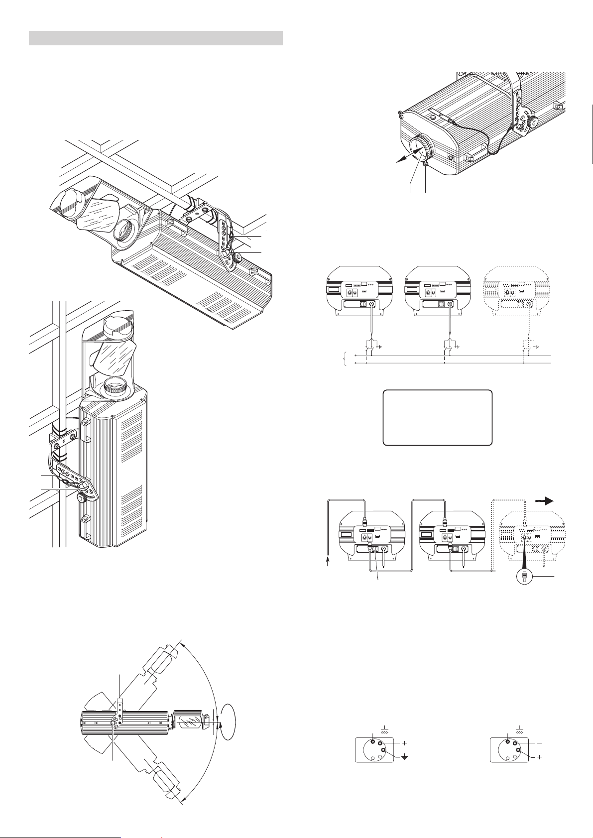
• Installing the projector
The projector can be installed on the ceiling or on a wall through the holes in the
bracket. It is recommended to use 2 screws ø12mm with nut and spring washer
.
CAUTION: Check the plates (3 and 4) are correctly secured to the sides of the
fitting; If the plates has been removed, to carry out non-routine maintenance
work, reposition them, following the relevant instructions and checking the
threads in the projector sides hold properly.
INSTALLATION AND FINE-TUNING
3
• Adjusting the projector position
180
°
50°
50
°
7
9
GOLDEN SCAN 3
• Adjusting the lens
Slightly unscrew the knob (20) and move the lens (21) until the projected image is
perfectly focused, then tighten the knob (20).
20
21
• Mains power connection
It is advisable to connect each projector via its own switch so as to be able to switch
it on and off individually from a distance.
N
L
Mains
BROWN =
BLUE =
YELLOW =
GREEN =
L
N
=
• Connecting the control signals RS 232/423 (PMX) - DMX 512.
The connection between projector and control unit and between different projectors
must be made with a cable conforming to the EIA RS-485 specifications: bipolar
braided, shielded, 120Ω characteristic impedance, 22-24 AWG, low capacity.
IMPORTANT: Do not use microphone cable or any other cable whose specifications
are different to the ones stated above.
The terminations need to be made with male/female connectors type XLR with
5 pins.
If using the DMX signal it is necessary to insert a terminal plug (22) on the last fitting
with a resistance of 120Ω (minimum 1/4 W) between terminals 2 and 3.
The terminal is not needed if using the RS232/423 (PMX) signal.
• Securing the safety ropes
Except for when the projector is standing on the floor, it is compulsory to fit the
safety rope (17). These need to be secured to the projector framework and then
hooked onto the eyebolts (5) screwed into the sides of the projector
IMPORTANT: The wires must make no contact with each other or with the metal
casing of the connectors. The casing needs to be connected to the braid of the
shield and to pin 1 of the connectors.
SIGNAL
SCREEN
SIGNAL
54
3
2
1
DMX
512
SIGNAL
SCREEN
SIGNAL
RS232/423
(PMX)
1
2
3
4
5
10
10
10
22
23
RS 232/423(PMX)
DMX 512
ENGLISH
 Loading...