

Page 1
Installation and operating instruction
Low Pressure Reducer Type EN 61-DS 1.5 kg/h
Issue 06.2010
Pressure reducer with integrated high-pressure relief for liquid gas devices
CONSTRUCTION
Low pressure reducer type EN 61-DS maintains outlet pressure at a constant level, within the prescribed range,
regardless of fluctuations of the inlet pressure (cylinder pressure or working pressure) and the changes in flow
and temperature.
Integrated high pressure relief "Lim" limits the outlet pressure to 100 or 150 mbar and thus prevents the delivery of pressure which is unacceptable for the connected devices. Integrated high pressure relief is consistent
with the requirements for devices preventing unacceptably high increase in pressure in accordance with the
TRF, BGV D34 "Use of Liquefied Petroleum Gas" DA to § 11 Part 4 and the EU directive concerning gas
equipment.
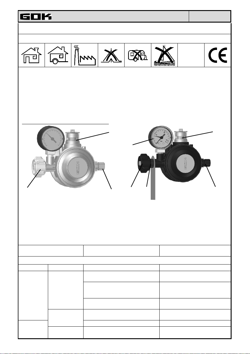
Low pressure reducer In the following versions:
⑤
④
①
• Pressure reducer according to DIN EN 12864.
• Pressure reducer according to DIN 4811-F.
• Each option with PRV pressure relief valve
reducing high pressure or with integrated safety
valve In case of pressure failure – see the drawing
on page 2.
This installation and operating instruction must be provided to the user and respected for its intended use and to
meet the guarantees.
For external devices
In household and industrial plants
OPERATING MEDIA
CONNECTIONS
Connection
Inlet ①
Outlet ②
(optional)
Connection for Dimensions According to the standards
Pressurised
gas cylinder
Pipe
Hose
G ¼ A - LH – KN with 45° internal
taper
②
Liquid gas (LPG In gaseous form)
connection to the large gas cylin-
GF
der, the weight of the fill, up to 33 kg
Comb.-A combined connection for
both small and large gas cylinders
with a hard or soft seal
KLF connection to the small gas cyl-
inder, the weight of the fill, up to 14 kg
Screw pipe connection with a cutting
ring
Internal thread G 1/4 DIN EN ISO 228-1
①
③
• Pressure reducer according to DIN EN 12864 Annex
B for the TRF requirements and industrial plants with
a thermally actuated blocking element (TAE) ③ and
manometer ④ to display the pressure at the inlet and
as a leakage control.
• Pressure reducer according to DIN 4811-F1-t.
For internal devices
In household and industrial plants
According to DIN 51622 / DIN EN
589 norms
DIN 477-1 nr. 1
DIN EN 12864 G.4
DIN 477-1 i DIN 4811-2
DIN EN 12864 G.5
DIN 477-1 nr. 2
DIN EN 12864 G.12
DIN EN ISO 8434-1
DIN EN 12864 G.15 ; H.9
DIN EN 560
DIN EN 12864 H.4
⑤
②
Page 2
•
⑥
Installation and operating instruction
Issue 06.2010
INSTALLATION
Before installation, the pressure reducer valve should be checked for any damage during
transport and whether the delivery is complete. The condition for the proper functioning of the
pressure reducer valve is its correct installation whilst observing technical rules, such as rules for
liquid gas TRF, required during the planning, building and operation of the device.
When choosing a pressure reducer valve with pressure threshold protection against high pressure pSO
100 or 150 mbar it should be remembered to adapt the connected equipment for its safe operation!
Pressure reducer valve with an option of pressure relief valve "PRV" (see the nameplate):
Using this pressure reducer valve indoors and in households is unacceptable. Due to the integrated pressure relief valve PRV (high pressure relief valve with limited flow pressure) liquid gas
can flow out to avoid unacceptably high pressure at the output and to protect the device.
Pressure reducer valve with an option of a safety valve in the case of
pressure failure "SBS":
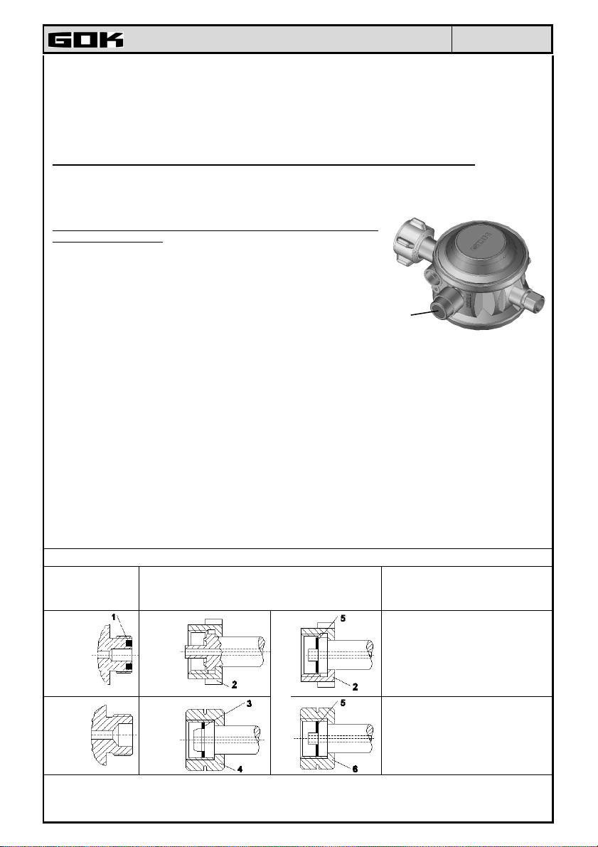
The reducers with integrated safety valve in case of pressure
failure (SBS) in accordance with DIN 12 864 the gas outlet clos-
es automatically if the rated flow rate exceeds by 10 - 40%, for
example in case of hose rupture or loosening of a hose connection. SBS closes tightly and completely after the onset of this sit-
uation and can only be re-opened after pressing the button ⑥.
Installation Tips
Installation should be performed using only spanners of suitable sizes. The connecting stub
pipes should always be held on the other side. Only the connectors made out of cast iron by
the pressure reducer housing, to be held on the other side. Do not use adjustable pliers for
piping.
• Before installing visual examination shall be performed for the presence of any metal chips or
other elements in the connectors. Such elements must be removed for example, by blowing
them out to exclude any interference to the operation of the device.
• Install the pressure reducer valve without the use of tension (do not bend it or twist it)
• Remember the direction of rotation for installation ➞➞➞➞!
• Install clean and undamaged seals!
• Winged-nuts and knurled nuts should be tightened by hand only. Do not use tools.
• When using outdoors the pressure reducer valve should be set or protected in order that
there is no water ingress.
•
Do not install the pressure reducer valve in an explosive area 0
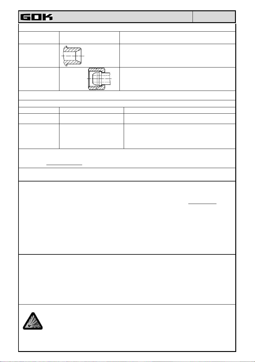
Installation of connectors, inlet at the pressurised gas cylinder LH = COUNTERCLOCKWISE THREAD!
Side stub connectors
Cylinder valve
weight
of the
fill up
to
14 kg
weight
of the
fill up
to
33 kg
Connection - inlet pressure reducer connect
with side stub pipes
KLF
Comb.-A
GF
.
Explanations
1 – Seal In the cylinder valve
2 – Union nut (wing-nut or knurled
nut)
5 – Soft seal of the pressure re-
ducer valve
2 – should only be connected
by hand!
3 - Seal of the pressure reducer
4 – Union nut (hexagon nut)
5 – Hard seal of the pressure re-
ducer valve
6 – Union nut (hexagon nut)
Page 3
nal
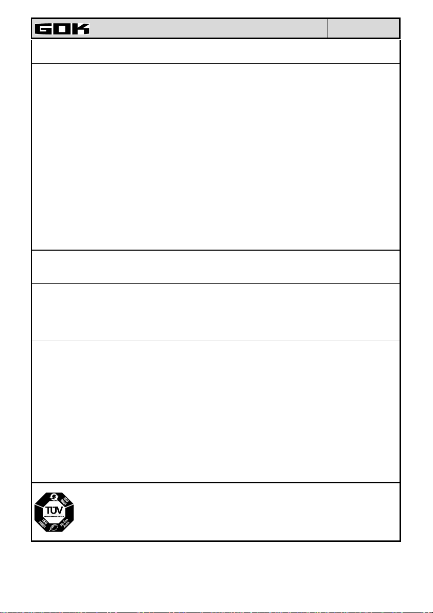
Installation of an external thread G ¼ A LH - KN (45 °inner taper) LH = COUNTERCLOCKWISE THREAD!
Subassembly
Installation and operating instruction
Drawing of the connect-
Explanations
Issue 06.2010
ing element
Pipe thread: cylindrical external thread G ¼ LH
Pressure
reducer
(„Left Hand“) n the tolerance class A according
to the standard DIN EN ISO 228-1 with 45 °
inner taper
Union nut with internal thread G ¼ LH according
Connecting
screw joint
to the DIN EN ISO 228-1standard, the end of the
hose with a sphere seal according to the DIN EN
560 standard
Tightening torque of 10 Nm
Mounting screw pipe connection with cutting ring
Subassembly Connecting element Explanations
Pressure
reducer
Connecting
screw joint
Installation according to instructions GOK regarding screw pipe connection with cutting ring according to the
DIN 2353 standard and DIN EN ISO 8434-1 based on the DIN 3859-2 standard.
The website www.gok-online.de in the "Service" section for the downloadable version.
After the tightening of the union nut the pressure reducer valve cannot be rotated. Turning can lead to
leaking connections.
Screw connector for an exter
diameter of the pipe ... mm
Stub pipes at outside
diameter... mm
screw pipe joint with cutting ring according to
DIN 2353 / DIN EN ISO 8434-1
① Precision steel tube, e.g. according to the DIN EN
10305-1standard
② Copper tubes, e.g. according to the DIN EN
1057standard: and not to TRF!
CHECKING FOR LEAKS
Before the first operation of the device with liquid gas it must be subjected to a leak check, also in case of cylinder replacement and after a long non-operational period of the device. To do this, turn off all locking elements
of connected devices and open the cylinder or tank valve. Then check the tightness of all connections using a
leak detector or other suitable foaming agent. Leakage control is positive only when it receives the result of
"tight".
Low pressure reducer valve with a monometer version:
Open the cylinder valve. Set the red pointer by turning it to align with the black indicator (cylinder pressure indicator) to determine the actual pressure in the cylinder. In the case of a monometer without the red indicator,
manually mark its position. Close the cylinder valve. Waiting time: 2 minutes, in order to equalise the temperature. Eventually, set the red pointer. Duration of control: 10 minutes. The indicated gas pressure cannot reduce
during the control period. If the pressure drops, check the tightness of the entire liquid gas system.
Do not use an open flame to check the sealing!
STARTING
The pressure reducer is ready for operation immediately after installation and following a successful LEAK
CHECK. Commissioning takes place through the opening of the cylinder valve or container with closed locking
elements of the connected device. Now the connected device can be operated as indicated in the manual observing applicable regulations for installation (e.g. TRF rules).
In the case of pressure reducer valves with safety relief valve in the event of pressure failure (SBS), press and
hold down the switching button until the pressure is equalized in the tubes (the time depends on the length of
the connected tubes) and then slowly release the switch. Now you can operate the connected device in accordance with the operating instructions.
HANDLING
LPG is a flammable gas! The relevant laws, regulations and technical rules must be observed!
It is recommended that during the operation of the devices for liquefied gas at specified time intervals, LEAK CHECK of the pressure reducer valve is conducted.
In the case of rising gas odour, leakage, escape of gas through the pressure relief valve PRV and connected
device fault TURN IT OFF IMMEDIATELY! It must be repaired by a specialised company.
Page 4
Installation and operating instruction
Issue 06.2010
Do not move the gas cylinder during operation! When tightening and loosening the connections at the cylinder
valve, turn the unit nut only.
OPERATIONAL CONTROL of the pressure reducer valve:
Visible faults of the connected device: abnormal flame.
Pressure reducer valve with thermally actuated locking element (TAE)
At temperatures above +100°C the blockade is activa ted, which itself blocks the gas flow. After activation
of the thermal blockade, this low pressure reducer may not be used anymore and should be replaced.
Gas leaks by the pressure relief valve PRV /activation of the protection against high pressure
For long-term gas leak by the pressure relief valve PRV or at the moment of activation of the protection preventing high pressure Lim, this pressure reducer valve must be replaced with a new one.
Pressure reducer with indicator
After starting the operation of the device, the indicator ⑤ should show green colour If the outlet pressure exceeds 80 mbar (only for the versions with the outlet pressure of 29 and 50 mbar), the indicator changes to red.
If after restarting the indicator is still red, this pressure reducer valve must be replaced with a new one.
Safety valve activation in the case of pressure failure (SBS)
In the case of safety valve activation in the event of pressure failure it is important to check the tightness of the
whole gas installation (e.g. hoses, connection points). After checking the tightness the pressure reducer can be
restarted.
SWITCHING OFF THE DEVICE
Close the cylinder valve or container, and then the blocking elements of the connected device. When not using
the device for liquid gas, close all valves.
REPAIR
If the recommended measures in the section on STARTING and HANDLING do not lead to a proper
RESTART, and the error cannot be determined, then the pressure reducer valve must be returned to the manufacturer for checking. Unauthorised tampering with the device leads to loss of approval and guarantee.
In normal use, and to ensure proper operation of the device it is recommended that the pressure reducer valve
be replaced after 10 years from the date of manufacture.
SPECIFICATIONS
Maximum allowable
pressure
Inlet pressure p Type EN 61-DS: 0,3 – 16 bar Nominal outlet pres-
Nominal flow Mg
Protection against high
pressure „Lim“ Operational pressure pSO
Temperature range TS:
Safety valve in case of
pressure failure
Other technical data (special versions) see the nameplate on the pressure reducer valve!
PS 16 bar
sure p
d
Type EN 61-DS: max. 1,5 kg/h Operational pressure
PRV
100 mbar
or 150 mbar
-20 °C ÷ +50 °C
value of operation 10 - 40%
1)
1)
at pd = 100 mbar
above nominal value of flow
29 (30), 37, 50, 67 or
1)
100 mbar
80 – 120 mbar
GOK Regler- und Armaturen-Gesellschaft mbH & Co. KG
Obernbreiter Straße 2-16, D-97 340 Marktbreit +49 9332 404-0 Faks +49 9332 404-43
E-Mail: [email protected] Internet: www.gok-online.de
No art. 01150-50a Replaces the issue 11.2006
 Loading...