

Page 1

AG3000T
USER MANUAL
AG3000T AG3000T-LS
User Manual: AG3000T
Version: 1.0
Issue Date: May 2016
AG3000T (print & apply system) with optional label unwinder
Page 2

Contents
1. Introduction ................................................................................................................................................4
1.1 Overview ...................................................................................................................................................4
1.2 Applicator Specifications Summarized .....................................................................................................4
3. Basic Safety Precautions .............................................................................................................................5
3.1 Coverage .............................................................................................................................................5
3.2 Following the instructions in this operating manual ..........................................................................5
3.3 Possible device handling risks .............................................................................................................5
3.4 Environmental conditions of the device operation ............................................................................5
3.5 Occupational health and safety rules .................................................................................................6
3.6 Safety instructions ..............................................................................................................................6
3.7 Never: .................................................................................................................................................7
3.8 Applied harmonized standards and the safe use of electrical appliances ..........................................7
3.9 The possible risks of electric shocks if working with the applicator ...................................................8
3.10 Configuring the pneumatic unit, safety ..............................................................................................8
4. Contents of delivery - what’s in the box? ...................................................................................................9
4.1 Standard configuration with 170 mm effective stroke .......................................................................9
3.2 Checking the box contents (AG-3000-110060 / AG-3000-110100) ..........................................................9
3.2.1 Box 1: Printer + Accessories ..............................................................................................................9
3.2.2 Box 2: Applicator components ....................................................................................................... 11
5. Assembling the system ............................................................................................................................ 13
5.1 Required Tools ................................................................................................................................. 13
5.2 Assembling the stand ...................................................................................................................... 13
5.3 Installing the internal rewinder in the printer ................................................................................. 17
5.4 Installing the applicator interface .................................................................................................... 19
5.5 Integrating the printer and applicator unit ..................................................................................... 21
6. Operating your AG3000T(-LS) .................................................................................................................. 26
6.1 Print & apply cycle: the basics ......................................................................................................... 26
6.2 Printer configuration for applicator use ........................................................................................... 26
6.2.1 Power on the printer ................................................................................................................... 26
5.2.2 Firmware ......................................................................................................................................... 27
5.2.3 Setting the printer in applicator mode ........................................................................................... 27
5.2.4 Formatting the applicator interface (!) ........................................................................................... 29
5.2.5 Smart backfeed ............................................................................................................................... 29
5.2.6 Create a label and load media ........................................................................................................ 29
6.3 Putting the applicator into service .................................................................................................. 29
6.3.1 Air supply ..................................................................................................................................... 29
2
Page 3

5.3.2 Checking the mechanical settings (!) .............................................................................................. 29
5.3.3 Run a test cycle ............................................................................................................................... 31
5.3.4 The “START” menu ......................................................................................................................... 31
5.3.5 The “SERVIS1” menu ....................................................................................................................... 33
5.3.6 The “MANUAL” menu ..................................................................................................................... 33
5.3.7 The “LANGUAGE” menu ................................................................................................................. 34
6. Mechanical and pneumatic adjustments ................................................................................................. 35
6.1 Manual menu ................................................................................................................................... 35
6.2 Applicator head alignment ............................................................................................................... 35
6.2.1 Height adjustment .......................................................................................................................... 37
6.2.2 Horizontal adjustment after vertical adjustment ........................................................................... 37
6.2.3 Horizontal adjustment without vertical adjustment ...................................................................... 37
6.3 Air settings i: blowing ...................................................................................................................... 38
6.4 Air settings ii: vacuum ...................................................................................................................... 39
7 Connecting to auxiliary systems .............................................................................................................. 40
7.1 Introduction..................................................................................................................................... 40
7.2 Triggering devices – input signals .................................................................................................... 41
7.3 Outgoing signals ............................................................................................................................... 41
8 Options .................................................................................................................................................... 42
9 Maintenance ............................................................................................................................................ 42
10 Wire diagrams ...................................................................................................................................... 43
10.1 Power and signals schematic ............................................................................................................ 43
10.2 Control unit picture .......................................................................................................................... 43
10.3 Power circuits ................................................................................................................................... 44
10.4 Connector rack - detailed view ......................................................................................................... 44
10.5 Connector rack diagram ................................................................................................................... 41
10.6 Electro-pneumatic diagram ............................................................................................................. 42
10.6 PLC / Printer applicator port diagram ....................................................................................... 42
3
Page 4

1. Introduction
Item no:
AG-3000-110060 / AG-3000-110100
AG-3000-22L060 / AG-3000-22L100
1.1 Overview
Godex AG3000 print & apply systems match ZX1000i printers, either with 203, 300 or 600dpi print
resolution, with high end, air-driven tamp applicators with the purpose of print and apply labels
on demand.
AG3000 print & apply systems are available as easy to install, ready-to-use solutions, but you can
also configure your own customized systems by combining the components in a different way. The
AG3000 enables you to attach unique information to each single product coming down the
production- or packaging line. The systems come with standard applicator heads of either 60mm
x 60mm or 100mm x 100mm. With optional heads they can handle any label size from 20mm x
20mm up to 100mm x 200mm. Tamp applicators are typically used to label non-moving items on
intermittent conveyor systems, in robotized processes, and in manual workflows. With roll-on and
blow-on heads, available on request, they will also label moving items accurately. The AG3000T
delivers an effective stroke of 170mm (total stroke 300mm) and the AG3000T-LS of 370mm (total
stroke 500mm). Various options are available to tune the AG3000T/AG3000-LS to your particular
needs.
1.2 Applicator Specifications Summarized
Type:
Std. head size: 60mm x 60mm / 100mm x 100mm
Opt. head sizes: 20mm x 20mm up to 110mm x 200mm
Stroke 300mm 500mm
Effective Stroke 170mm 370mm
(The effective stroke equals the maximum allowed height difference between the products in
one production batch)
Label sizes min 20mm x 20mm, max 100 x 200mm
Label roll diameter 200mm standard inside the printer
Performance up to 30 labels/min of 100mm x 100mm at an effective stroke of 170mm
up to 60 labels/min of 20mm x 20mm at an effective stroke of 10mm
Compatible printers ZX1200i (203dpi) / ZX1300i (300dpi) / ZX1600i (600dpi)
)*: the process speed depends on variables such as label size, the type and source of the data
processed, stroke length (product height), required product contact time and conveyor speed.
AG3000
60mm x 60mm / 100mm x 100mm
20mm x 20mm up to 110mm x 200mm
280mm optional with external holder
AG3000-LS
4
Page 5

Basic Safety Precautions
Coverage
Safety rules and instructions either written or referred to in this manual apply to the installation, the
usage and the maintenance of both the applicator- and the printer components within AG3000
systems. They do however not replace any safety instruction published in separate Godex
ZX1(X)00i user- and service manuals, and must be considered complementary to those instead.
Therefore, personnel working with AG3000 systems must be familiar with the safety instructions
stated in the applicable Godex printer manuals as well.
Following the instructions in this operating
manual
A thorough knowledge of basic safety instructions and safety regulations is an essential
prerequisite for using this device in accordance with safety requirements, while ensuring its faultfree operation. This operating manual, and in particular the safety instructions contained herein,
must be adhered to by any personnel using the device. All relevant standards and regulations
pertaining to the prevention of accidents and injuries relevant to the device installation site must
also be adhered to.
Possible device han dling risks
The device was manufactured in accordance with relevant technical requirements and
internationally recognized safety and technical standards. However, situations might still arise
during the use of the device that could pose a risk to the health and/or lives of operators and/or
third parties, or cause damage to the device and/or other property.
The device may only be used:
• In accordance with the purpose for which it was manufactured
• If it is free of any defects in terms of safety and technical requirements.
Any defects that could potentially compromise safety must be rectified immediately.
Environmental conditions of the device
operation
• Operation ambient temperature within the range of 5 °C to 40 °C (41 °F to 104 °F)
• Storage and transport temperature: -20 °C to 55 °C (-4 °F to 131 °F); the device can withstand
temperatures of up to 64 °C (149 °F) for a period of up to 24 hours
• Operation ambient non-condensing relative air humidity within the range of 20% to 85% RH
5
Page 6

• Storage ambient non-condensing relative air humidity within the range of 20% to 85% RH
Occupational health and safety rules
The device contains moving parts that can pose a risk to the operator unless the safety rules are
adhered to. In order to prevent a potential injury, read the following safety rules carefully:
• Only persons trained in operating the device and acquainted with associated risks should be
authorized to enter the space where the device is installed.
• A safe distance from the application plate must be maintained when the device is being
connected to a source of compressed air and/or when it is being switched on or off, as the
device may begin to move unexpectedly.
• Crumpled and/or detached labels may only be removed when pressurized air is not being
supplied to the device or if the device has moved into an error mode.
• An error or pause mode must be invoked before print material is replaced in the device.
Safety instructions
• When working with the device the operator must adhere to all relevant generally binding
safety regulations as specified in the labor code of his/her country and in other legal safety
regulations that may apply.
• The device’s keeper must ensure the performance of regular maintenance. Routine
maintenance must be carried out by properly trained and authorized personnel. Failure to do so
could result in device failure or injury and may breach health and safety laws.
• The device may only be operated by properly trained and authorized personnel.
• The device may only be used for those purposes for which it is technically fit in accordance with
the terms and conditions specified by the manufacturer, while the structure, design and technical
condition must comply with the relevant safety regulations.
• The device’s operator must perform a visual inspection of the device regularly, along with
regular basic maintenance and servicing.
• Should there be a discovery of any defect and/or damage that might compromise operating
safety and/or the operation of the printer that cannot be rectified on the spot, the device must
not be brought into operation / must be switched off immediately, and the defect must be
reported to the device’s keeper and other relevant persons.
• The legibility of safety signs, symbols and notices on the device must be maintained at all times.
In the event of damage and/or illegibility, any such signs must be restored by the device’s keeper
to their original condition.
6
Page 7

Never:
• Connect the device to a source of electric power if any of the protective parts (electric
component covers, safety labelling and/or safety elements of the device) have been removed
and/or damaged.
• Modify the mechanical design and/or electrical circuitry of the device in any way.
• Perform any maintenance tasks before the device has been secured in its off state and the
device has been disconnected from the main power.
Applied harmonized standards and the safe
use of electrical appliances
• AG3000 Print & Apply systems are class I electrical devices in terms of the necessary protection
against electric shock in accordance with harmonized standard EN 61140, ed. 2 and hence also
meet generally acknowledged standards such as, but non only CE, meaning that all non-live
conductive parts are mutually conductively connected and are further connected to the
protective earth conductor of the printer’s power supply. Other harmonized standards that have
been applied, are EN 60439-3, applicable to low-voltage switch gear and EN ISO 12100 regarding
the safety of machinery.
• Connection to the power network supply must be made in compliance with the
requirements specified in regulations and technical standards valid and applicable in the
country of operation.
• Any work on the device may only be performed by persons who are duly qualified according to
the legislative code of the country where the device is installed (1) and who has been
acquainted to the necessary extent with the device (2).
• The keeper of the device is obliged to secure the performance of inspections of the electrical
device in prescribed intervals and to do so in accordance with the legislation regarding such
inspections applicable in the country of operation.
• The device may not be dismantled.
• If shielded data cables are used with the device, they must comply with international standards
governing devices producing electromagnetic radiation. The utilised data cables must be
completely shielded. The use of shielded data cables is necessary in order to prevent the
production and/or reception of electromagnetic noise. Using non-shielded data cables may
result in electromagnetic radiation exceeding permitted limits.
7
Page 8

The possible risks of electric sh o c ks i f working
with the applicator
Despite the application device being manufactured in accordance with relevant technical
regulations pertaining to safety, its technical design cannot preclude all risks that may occur,
especially in the event of careless or negligent behavior during use of the device. The device must
be used with full awareness of the following risks of electric shock:
• Resulting from direct or indirect contact with parts designed to conduct electric current (live
parts), direct or indirect contact during the removal of electric equipment covers, or direct or
indirect contact in the event of damage caused to insulating parts of a movable power cord;
• Caused by damaged parts of electrical equipment;
• Resulting from a failure to observe instructions regarding equipment connected to the power
mains.
Configuring the pneumatic unit, safety
Excessive operating pressure may cause:
• Injury by crushing;
• Mechanical damage to parts of the labelling machine.
The equipment manufacturer configures the pneumatic unit of the labelling machine in a manner
that ensures all pneumatically controlled parts of the device (e.g. the piston) can be stopped by
hand without the use of excessive force (max. 150N)
The customer shall bear responsibility for any adjustments that are not made by the equipment
manufacturer prior to delivery.
8
Page 9

Contents of delivery - what’s in the box?
Standard configuration with 170 mm effective
stroke
Most likely you ordered a standard configuration with a 203dpi printer 170mm effective stroke: the
AG-3000- 110060 or AG-3000-110100 (the only difference between those two is the size of the
applicator heads included: 60mm x 60mm versus 100mm x 100mm). Therefore, and because the
installation and operation of most configurations are identical, we will use this standard
configuration to guide you through the installation and make you familiar with the usage of the
AG3000 print & apply solution. Further in this manual you find an option list.
3.2 Checking the box contents (AG-3000-110060 / AG-3000-110100)
You have received two boxes. Please check whether their content has arrived undamaged. §
3.2.1 and 3.2.2 will help you to check whether nothing is missing. Please inform your supplier
immediately if anything seems to be wrong.
3.2.1 Box 1: Printer + Accessories
If you have received the printer parts for your AG3000 directly from a Godex subsidiary the printer
box contains the printer components described below here. In case you have purchased the
printer and options through a Godex distributor or dealer you may receive them in separate
boxes. In that case it is also possible the internal rewinder and applicator interface have been preinstalled.
• 1x GoDEX ZX1200i 203dpi printer (optional: ZX1300i dpi printer, ZX1600i 600dpi printer)
9
Page 10

• 1x GoDEX ZX1(X)00i applicator interface, item no. GP-031-Z2i003-001:
• 1x GoDEX ZX1(X00i) peeler/rewinder unit, item no. GP-031-Z21005-000
10
Page 11

3.2.2 Box 2: Applicator components
A- Parts to build heavy duty floor stand item AG-2000-123322
B-From left to right:
Positioner (AG-2000-110110) (AG-2000-110108)
700mm tube (AG-2000-110112)
90° clamp for use with positioner (AG-110106)
C- Applicator machine clamp
D- Control Unit
11
Page 12

E- AG3000T applicator base plate, piston, mounting material, applicator head.
(Item AG-3000-110060, AG-3000-110100, AG-3000-22L060, or AG-3000-22L100)
12
Page 13

Assembling the system
Required Tools
• Hex wrenches 4, 5, 6, 8
• Socket wrench 15
• Screwdriver set
• Phillips head screwdriver set
Assembling the stand
Please preview all steps and parts described below here before you start assembling. It will help you
to anticipate on every step to come.
Picture 1 – 3: mount the four round feet to the corners of the 2 longer alloy profiles (check also pic.
4 + 5!):
Pic. 1 Pic. 2 Pic. 3
Picture 4: mount the feet on the faces which do not have screw holes
Picture 5: let the narrow ends of the screw holes face each other on the inside whilst mounting the
feet.
Pic. 4 Pic. 5
13
Page 14

Picture 6: the height of each foot is adjustable to level the stand on uneven surfaces
Picture 7: close the ends of the alloy profiles with the black plastic covers
Pic. 6 Pic. 7
Picture 8: place the shorter alloy leg (the one with holes on two faces) between the longer
legs. Make sure the wider ends of the screw holes are on the same side as the feet.
Picture 9 - 10: firmly connect the three legs
Pic. 8 Pic. 9
Pic. 10
14
Page 15

Picture 11 - 13: take the remaining profile (pic. 11) and mount it firmly onto the central leg:
Pic. 11 Pic. 12 Pic. 13
Picture 14 - 16: mount the adapter plate and clamp on the top of the vertical profile.
Pic. 14 Pic. 15 Pic. 16
Picture 17-18: insert the 700mm tube into the floor stand:
Pic. 17 Pic. 18
i: now first see the appendix “AG3000 OPTIONS” plier in case you also received the
demonstration / exhibition kit AG-3000-EXHKIT.
15
Page 16

Picture 19-20: mount clamp 110106 onto the slide inside positioner 110110 and then mount the
positioner on the upper end of the 700mm tube:
POSITIONER
AG-2000-110110
CLAMP
AG-2000-110106
Pic. 19 Pic. 20
Picture 21: at a later stage the end of the horizontal positioner must be inserted in- and firmly
attached to clamp 110108, which is pre-mounted on the applicator unit:
Pic. 21
16
Page 17

Picture 1:
Picture 2:
Installing the internal rewinder in the printer
Step 1. Open the main printer cover
Step 2. Remove the three screws holding the left side
cover
Step 3. Remove the lower front cover
Step 4. Remove the plug from the center plate
(The rewinder bearings will be inserted here)
Step 5. Remove the left cover
Picture 3:
Step 6. Insert the first bearing from the right side
Picture 4:
17
Page 18

Picture 4:
Step 7. Insert the second bearing from the left sight
Picture 5:
Step 8. SKIP this step! Not relevant for applicator use.
Step 9. SKIP this step! Not relevant for applicator use.
Step 10. Install the diverter pulley
Picture 6:
Step 11. Insert the rewinder shaft into the bearings
Step 12. Install the “rewinder full” sensor
Step 13. Plug in the sensor connector
Step 14. Remove the motor.
Step 15. Install the 22T cogwheel and its retaining ring.
Step16. Install the motor and the rewinder drive belt
Step 17. Install this gear set
Step 18. Install this gear set
Step 19. Install the clutch
i: The default torque setting of the clutch suits the AG3000 requirements. Please check the
printer service manual in case the torque needs to be adjusted at some point.
i: GO TO § 4.4 (APPLICATOR INTERFACE INSTALLATION) BEFORE RE-INSTALLING THE PRINTER
COVER!
18
Page 19

Installing the applicator interface
The GoDEX ZX1X00i applicator interface can be used with both 24V and 5V peripheral systems,
both in terms of power supply and in- and outgoing signals. Hence, the correct voltage levels of
the in- and outgoing signals must be configured before installation in the printer. Even in case the
interface board has been pre-configured you must verify the setup is correct. You may need to
(re)configure the board to be compatible with the AG3000. The AG3000 requires the 24Volt
configuration. A wrong configuration may damage your equipment!
Picture 1: check whether the configuration of the applicator interface board is set correctly for use
with the AG3000 applicator series. Adjust it if necessary. Picture 1 shows the correct configuration.
A. The two pins on J4
must be connected.
B. Pin 2 and 3 on J5
must be connected.
C. Pin 2 and 3 on J6
must be connected.
Pic. 1
Picture 2: the applicator interface board with the three loose jumpers and mainboard flat cable.
Pic. 2
19
Page 20
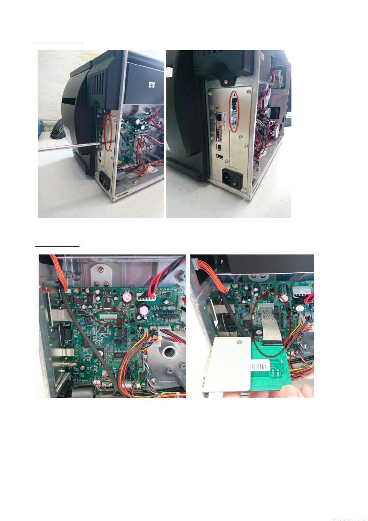
Picture 3 and 4: remove this cover on the back of the printer
Pic. 3 Pic. 4
Picture 5 and 6: connect the applicator interface to the socket on the mainboard:
Pic. 5 Pic. 6
20
Page 21

Picture 7 + 8: place the external connector in the slot and tighten the screws from
outside
Pic. 7 Pic. 8
Picture 9 - 11: remount the left printer cover:
21
Page 22
Integrating the printer and applicator unit
After installing the internal rewinder and applicator interface it is time to mount the printer on the
applicator. You do this by following the steps showed in the following pictures.
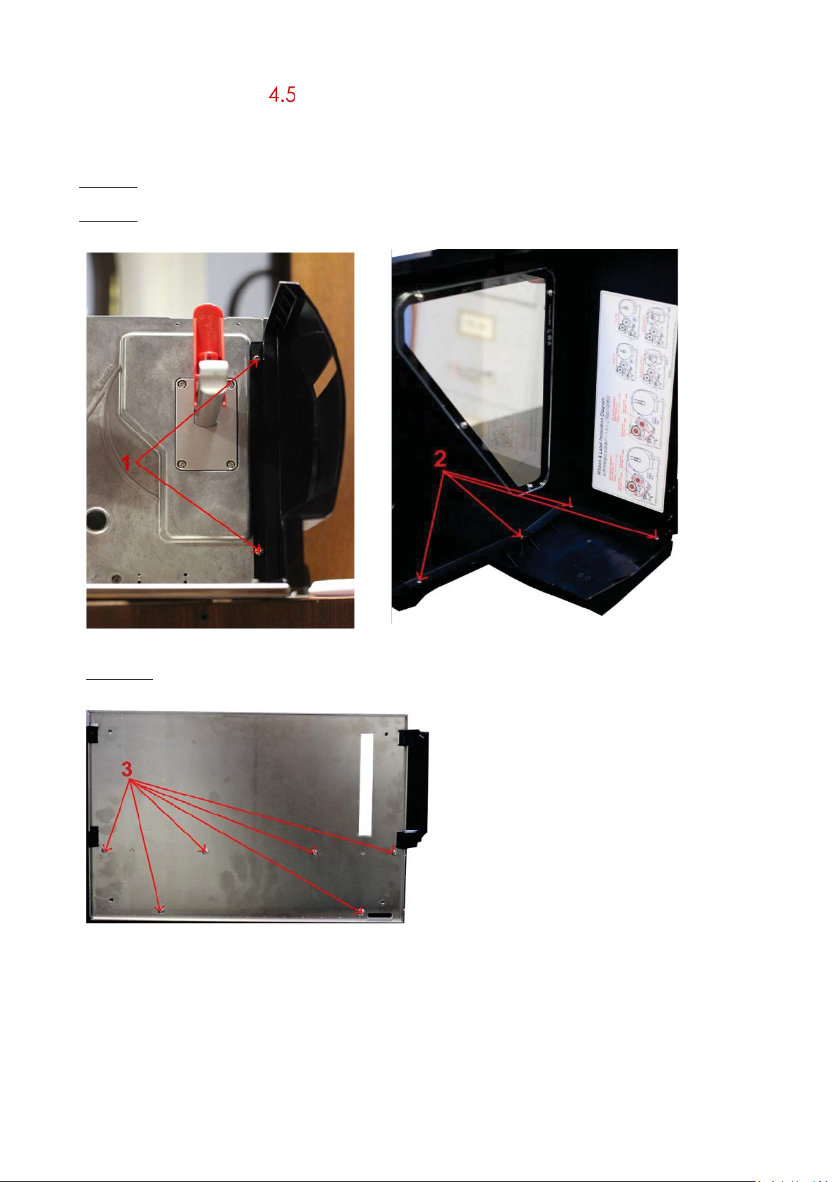
Picture 1: unscrew the screws indicated with “1” and remove the printer’s back cover
Picture 2: unscrew the screws indicated with “2” and remove the printer’s front cover
Pic. 1 Pic. 2
Picture 3: unscrew the screws indicated with “3” and remove the bottom plate from the printer.
Pic. 3
21
Page 23
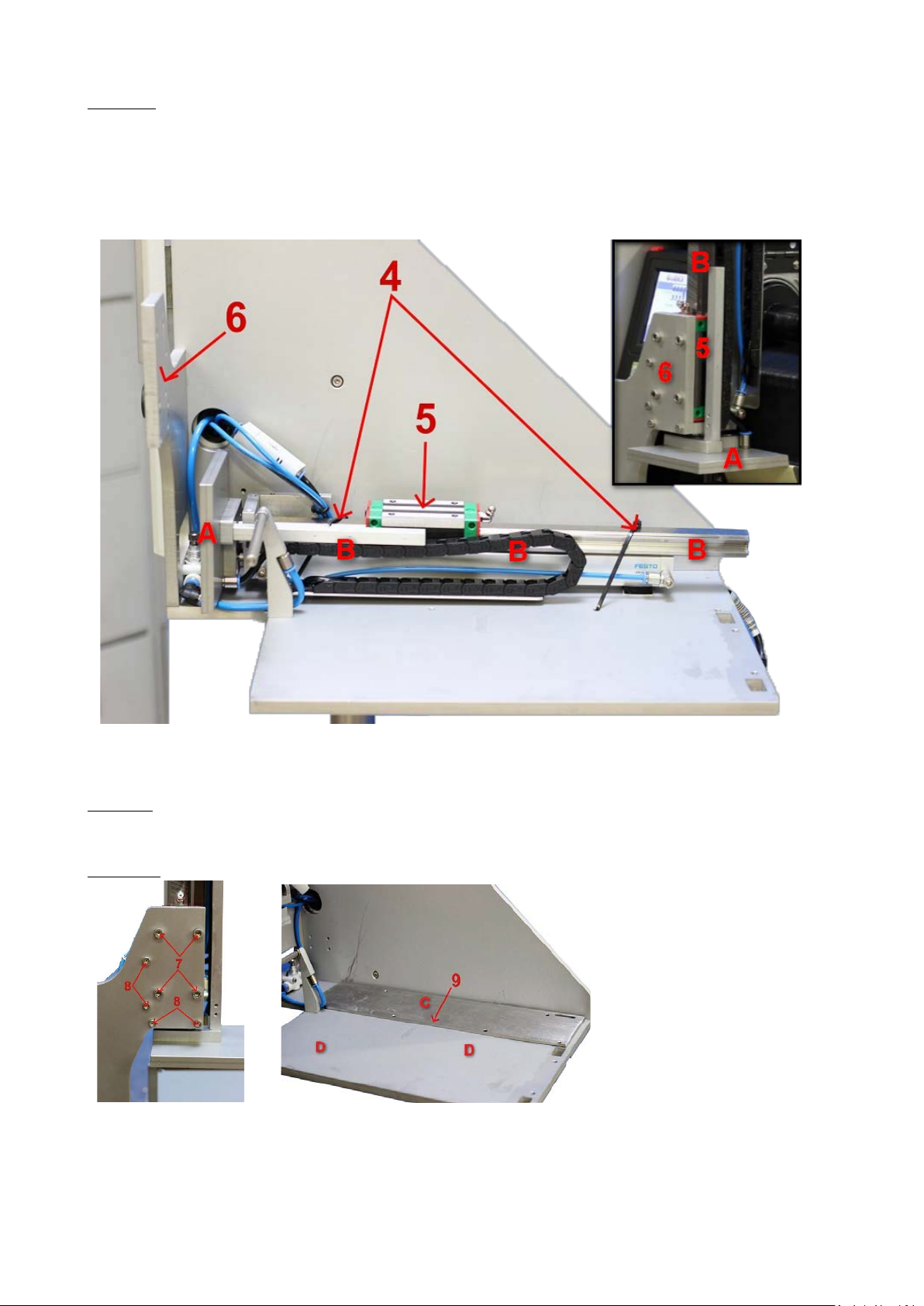
Picture 4:
• Remove the tie wraps (4)
• Move the slide (5) as far as possible towards the applicator head (A)
• Lift up the piston (B) including the slide and tubes and place the slide (5) against surface “6”
Pic. 4
Picture 5: mount the slider to the bracket with 4 bolts M5x16 and tighten properly (step 7) mount
the pneumatic cylinder bracket with 4 bolts M4x16 and tighten properly (step 8)
Picture 6: place adapter plate “C” onto the applicator main frame “D” (step 9)
Pic. 5 Pic. 6
22
Page 24

Picture 7: place the prepared printer onto adapter plate “C” and main frame “D”
Pic. 7
Picture 8: mount the printer E on main frame D with 6x M4x16 and tighten properly (step 10)
Pic. 8
23
Page 25
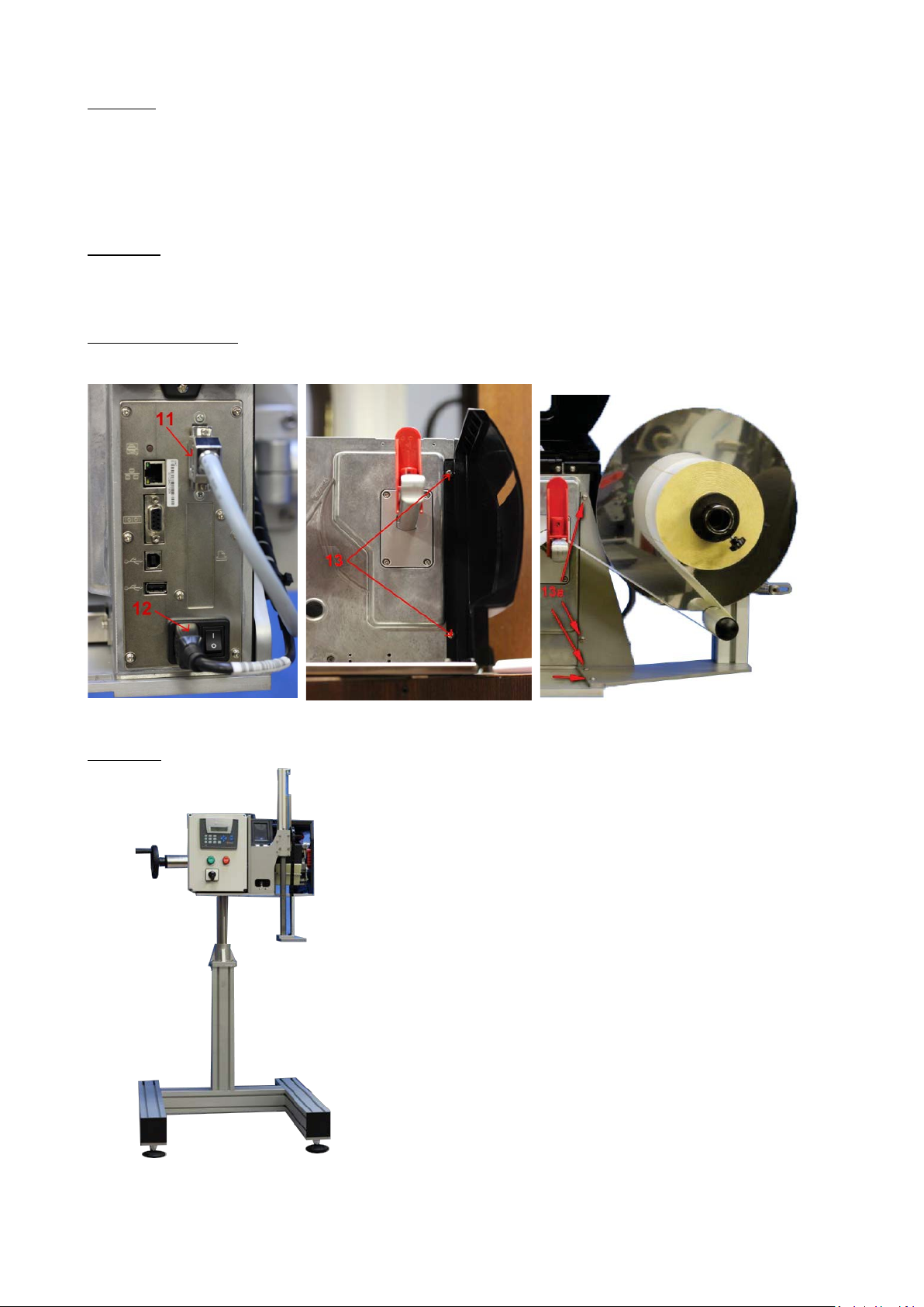
Picture 9:
• Connect the I/O interface cable coming from the control box to the printer’s
applicator port (step 11)
• Connect the power cable coming from the control box to the
printer (step 12)
Picture 10:
• Remount the rear printer cover (step 13 - not applicable if you install the optional
label unwind stand)
Picture 11 (optional):
• Mount the optional label unwind stand (step 13a)
Pic. 9 Pic. 10 Pic. 11
Picture 12: your AG3000 system should look like this now and is ready
Pic. 12
24
Page 26

Operating your AG3000T(-LS)
Print & apply cycle: the basics
The labelling cycle is initiated by the START signal, given by the applicator control box. The cycle
can only begin if the buffer memory of the printer is provided with data, the printer READY signal
to the applicator is on and the applicator operating status is RUN. Once the START signal is given,
the control unit instructs the printer to print a label, while simultaneously the blow valve (OFUK) is
opened. The lower blow nozzle ensures the secure detachment of the label from the carrier tape
and its transfer onto the application head using suction. The label is secured in place on the
application head by a vacuum. Subsequently the piston rod lowers the application plate onto the
product to apply the label, before the application plate is returned to its upper standby position,
thus completing the application cycle.
Data exchange may take place between the printer and auxiliary systems via one or more of the
available interfaces on the printer (USB, LAN, SERIAL, USB Host as well as optional WIFI and BT). No
data are sent to the printer via the applicator control unit.
Printer configuration for applicator use
5.2.1 Power on the printer
1) Properly ins er t the applicator control box’s power cable into a 240V AC socket
2) Switch on the main switch on the control box (Pic. 1) .
3) Switch on the main switch on the back of the printer Pic. 2).
4) Push the power button beneath the printer display (Pic.
Pic. 1 Pic. 2 Pic. 3
26
Page 27

5.2.2 Firmware
The recommended fir m ware version for applicato r usage is V2.Y06 (April 2016). Please
always verify with your supplier or directly with GoDEX whether updates have been
released. The current s u pportive display firmware is 2.003 (April 2016).
5.2.3 Setting the printer in applicator mode
Set and lock the applicator mode in the printer menu to enable correct and reliable
communication between the applicator control unit and the printer. The procedure is as follows:
Pic. 1: select "main"
setting"
Pic. 2: select "devices"
Pic. 3: select "option
Pic. 4: select "+". "None"
will change to "Applicator"
Pic. 5: select "option" to lock
the printer in applicator
mode
Pic. 6: select "check box" to
confirm the option settings
and leave the option menu
27
Page 28

Pic. 7: select the icon shown
below) to return to main menu
Pic. 8: Back on main menu
28
Page 29

5.2.4 Formatting the applicator interface (!)
It is necessary to format the applicator interface by sending the command ^XSET,APPLICATOR,0,1
to the printer. For more details, please see the printer manual.
5.2.5 Smart backfeed
The smart backfeed function is currently (April 2016) not supported in applicator mode.
5.2.6 Create a label and load media
Now create a label and store it on the printer. Always select the applicator mode in either the
software or the driver you are using. Load the printer with suitable media and TTR if applicable. The
printer is ready to go now. For more information regarding creating labels and handling the ZX
printer, please see the printer manual.
Putting the applicator into service
5.3.1 Air supply
Connect the AG3000 to a pressed air supply. The required pressure is at least 4,5bar. The system’s
air intake valve protects the applicator against too high pressure. You insert the end of an 8mm air
hose into the quick coupler on the backside of the control box:
Picture 1: AG3000 air intake coupler
5.3.2 Checking the mechanical settings (!)
Basically no adjustment of the mechanical parts is needed. During its production the applicator
has been tuned to be a perfect fit with the printer, out-of-the-box. But due to transportation and
re-assemblage certain elements might require fine-tuning after all. Therefore, it is a must to check
the correct position and - functioning of the crucial before putting the AG3000 into operation.
29
Page 30

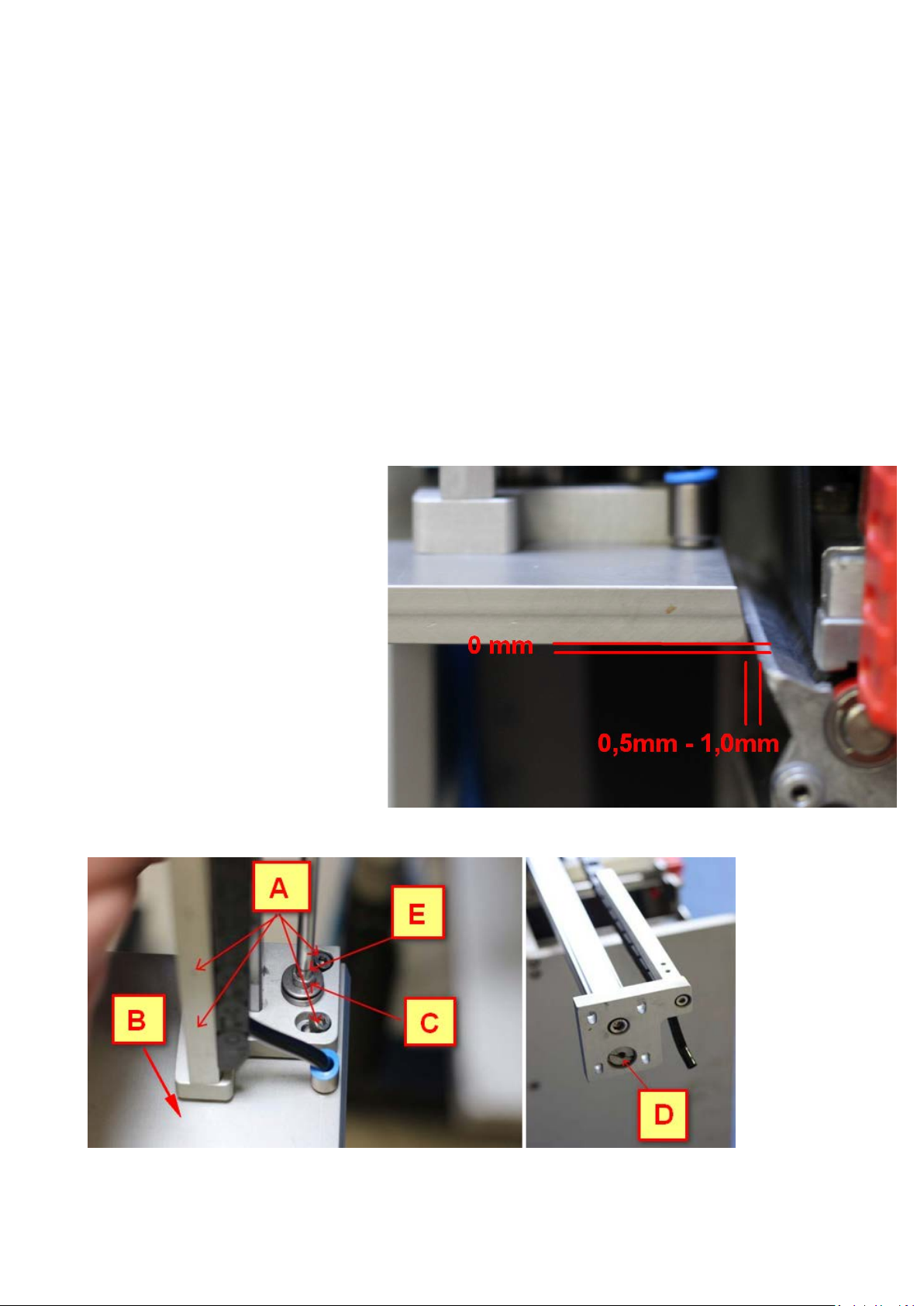
Please perform the following procedure:
Picture 1 & 2: Check the alignment of the application head (A) and the printer peeler edge (B).
• The horizontal distance between applicator head and peeler edge (1) must be 0,5mm to 1mm.
• The applicator head and the peeler edge must be aligned perfectly parallel to each other
• The bottom of the applicator head should be the same height (2) as the upper end of the peeler
edge.
• If the height has been set correctly the label will slightly bend down to move forward under the
head (3)
Picture 1
Picture 2
30
Page 31

5.3.3 Run a test cycle
After verifying the applicator and printer have been aligned properly (see § 5.3.2) and after the
printer has received the print data (see § 5.2.6) you can run a test cycle. The system must be in
“START” menu to do so.
Option 1: Enter key
1) At start-up the applicator display will show “STOP”
2) Push the START-button on the control unit to bring the system in “RUN READY”” mode
3) Select the “ENTER” key underneath the control box display to trigger one cycle
i: if the display will show “only “RUN” instead of “RUN READY” the applicator head is not in its start
position
Option 2: Triggering device
1) At start-up the applicator display will show “STOP”
2) Push the START-button on the control unit to bring the system in “RUN READY” mode
3) Activate the triggering device (e.g. switch, sensor, external PLC) in case you already
connected one.
i: if the display only shows “RUN” instead of “RUN READY” the applicator head is not in its start
position
Observe the way the labels travel from the print head onto the applicator head and then
towards the product. If the label is transported correctly no mechanical adjustment is needed.
Also in the course of long-term operation no adjustments are anticipated because the label
position is determined by the alignment of printer and applicator, which again is fixed.
How to proceed now:
1) Most probably your test results are positive which means your system is now READY TO USE. Go to
§ 5.3.4.
2) In case the label does not travel correctly or a cycle won’t start, it may be necessary to adjust
one or more of the stop positions of individual pneumatic parts. Also in that case we recommend
to first read § 5.3.4 - § 5.3.7. In case you prefer to adjust the mechanics first, please go to §6.
5.3.4 The “START” menu
Image 1: the system will start up in the „START“ menu, displaying either „STOP“ and „ERROR PRINT“
(in case the printer is not ready yet) or only „STOP“ (as soon as the printer is in „READY“ mode).
LCD display
STOP
Numeric keypad
“DOWN” arrow
ERROR PRINT
ENTER button
31
Page 32

Image 2: By pushing the START-button on the control unit you will bring the applicator from “STOP”
/
into “RUN” mode if:
• There does not occur an error in the applicator
• There does not occur an error in
the printer the screen will display
“RUN” and “READY”
!! In case only “RUN” is indicated you
cannot start a cycle. It means the
applicator head is not in its uppermost
position (start position). Check the
pneumatic cylinder in this case. Maybe
there is no air, or the sensor position is not
correct. The LED on the sensor must be
on!!
i: as soon as “RUN READY” is displayed
you can run a test cycle
Image 3: the display will show “ERROR”:
• In case an application cycle cannot
be completed after a predetermined
length of time (time out function)
Image 4: the display will show “ERROR PRINT”:
• In case the printer ran out of media
• In case the printer ran out of ink ribbon
• In case the print head is open
• In case no print file ready in printer buffer
ERROR
RUN READY
RUN
ERROR PRINT
i: the control box can also deliver error
signals to auxiliary systems. See § 7.1 - §
7.3.
Image 5: by selecting the DOWN-arrow
you will enter the “SERVIS1” menu.
32
Page 33
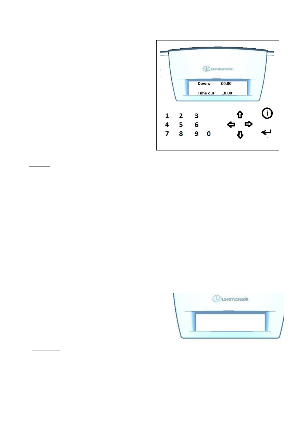
5.3.5 The “SERVIS1” menu
Image 1: in this menu you set 2 key
parameters.
Down
The time in seconds during which the applicator
head travels and remains down before returning
to its starting position.
In workflows in which objects of various sizes
are handled simultaneously this value must be
adjusted to the objects that require the
longest travelling time.
In case all objects require the same travelling
time the distance to the applicator base plate
can be minimized and with it the travelling
time. This ensures the highest possible system
speed.
Time out
This value in seconds determines the maximum duration of one application cycle. If a cycle has
not been completed within this length of time the system will go into error mode.
This function will stop the system if an error occurs after the initialization of an application cycle
and the cycle cannot be completed. Possible examples are the applicator head being
obstructed and lack of feedback from the printer.
Selecting and setting the parameters
1) The „DOWN“ value will be blinking automatically. Either change and confirm or only confirm
the pre-selected value with the „enter“ key. The cursor will jump to the „TIME OUT“ value.
2) Change and confirm or only confirm the pre-selected „TIME OUT“ value with „enter“. Exit menu
“SERVIS1”
Push the “START” button to return to the “START” menu Select the DOWN-arrow to go to the
“MANUAL menu
5.3.6 The “MANUAL” menu
Image 1: this menu is used to test individual
stages of the print&apply process. Can only
be used with the system in “STOP” mode. It is
not possible to test a full cycle in this menu.
MANUAL
1 x 2 x 3 x 4 x
Options are selected on the numeric keypad.
Select “1” to check the airflow through the
little tube underneath the print head. This
airflow blows the label towards the applicator
head.
Select “2” to check whether the applicator head vacuum works well.
33
Page 34

Select “3” to check whether the cylinder receives enough air pressure to go down and up.
Select “4” to check printer output (the printer will print one label if the input buffer is loaded)
You exit this menu with either the LEFT arrow (back to the SERVIS1 menu), the DOWN arrow
(further to the language settings) or the START button (back to the START menu).
5.3.7 The “LANGUAGE” menu
Image 1: in this menu you can select
any language included in the
AG3000 firmware.
1) You access this menu from the
MANUAL menu by selecting the
DOWN arrow key.
2) Use the arrow RIGHT key to select a
language
3) Leave this menu by selecting the
arrow LEFT key (back to the
MANUAL menu) or the START button
(back to the START menu).
CHOOSE LANGUAGE
EN
34
Page 35
6. Mechanical and pneumatic adjustments
6.1 Manual menu
You must first open the “MANUAL” menu to adjust mechanical settings on the applicator:
• Bring the device in stop mode
• Press the “DOWN” arrow whilst the device is in “STOP” mode to open the “SERVIS 1
menu”, confirm the preselected settings with “ENTER” and select the “DOWN” key again.
6.2 Applicator head alignment
It is required to align the applicator head in case:
• In start position its bottom is higher than the upper end of the peeler edge
• In start position its bottom is lower than the upper end of the peeler edge
• The distance between the head and the peeler edge is less than 0,5mm
• The distance between the head and the peeler is more than 1,0mm
• The head and the peeler edge are
not parallel Picture 1: correct
Alignment.
Picutres 2 & 3: re-align the applicator
head
35
Page 36

Pictures 2.
Picture 3
36
Page 37

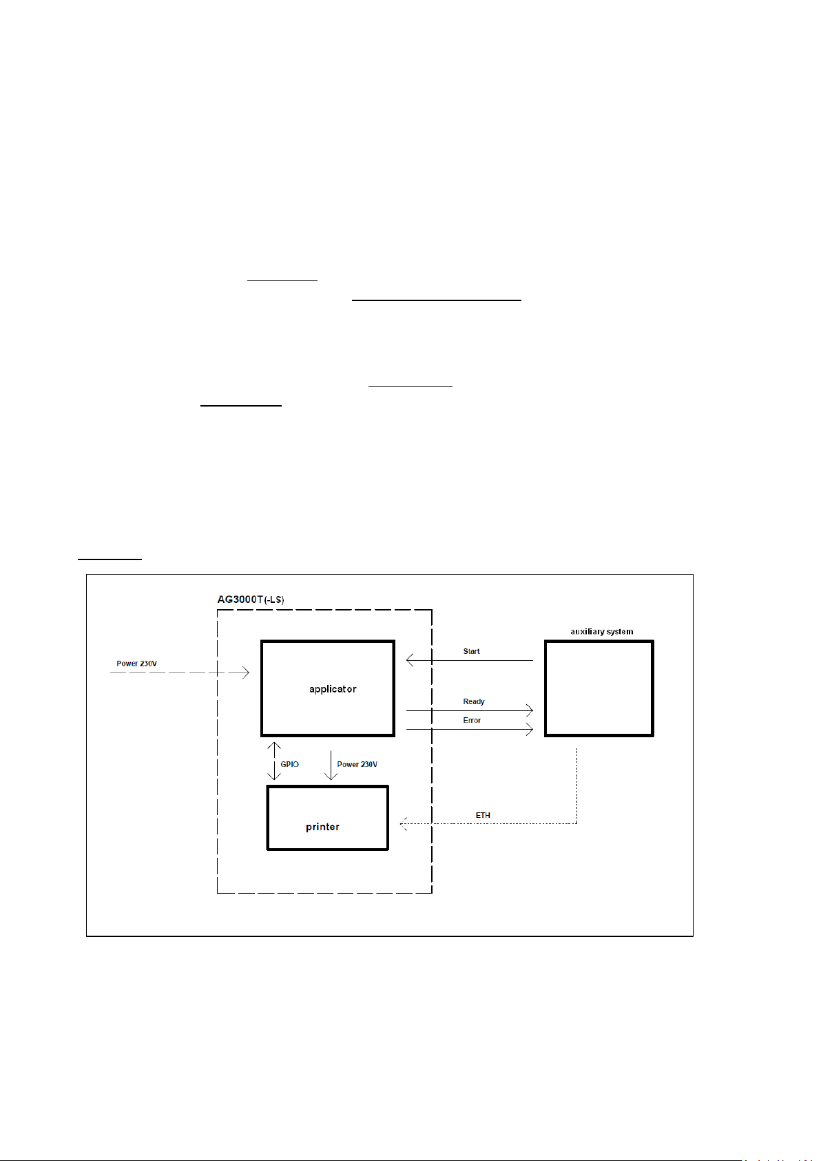
6.2.1 Height adjustment
1) Note the distance in mm the applicator head start position is too low or too high
2) Bring the applicator head in its lowest possible position by selecting “3” on the keypad
3) Remove screws (A) and remove the applicator head (B)
4) Loosen locknut (C) against nut (D)
5) Hold piston rod (E) and rotate nut (D) to move the applicator head bracket in the desired
direction 6/ tighten locknut (C) with the applicator bracket in the new position
7) Remount the applicator head but only loosely tighten the screws (A). You must still be able to
move the applicator head. Move the head as far as possible in the direction of arrow “F” (away
from the printer).
8) Bring the piston back in its upper position by selecting “3” on the keypad again
9) Check whether the vertical position (start position) is correct now. If not please repeat the
procedure until the vertical position is correct.
CONTINUE NOW WITH § 6.2.2
6.2.2 Horizontal adjustment after vertical adjustment
After adjusting the vertical start position of the applicator head it is always necessary to also set
the horizontal position again. You do so as follows:
1) Slide the applicator head towards the printer until it is 0,5mm – 1,0mm from the peeler edge
2) Make sure the peeler edge and applicator head are placed perfectly parallel to each other
3) Select key “3” on the keypad to bring the applicator head in its lowest position
4) Tighten the screws (A)
5) Select key “3” again to bring the applicator head back in start position
6) Verify whether the horizontal position is correct. If not repeat the procedure until all corrected.
7) Leave the MANUAL menu by activating the START button and run a test cycle
6.2.3 Horizontal adjustment without vertical adjustment
In case the original starting height of the applicator head is correct but you need to change the
horizontal position of the head, you proceed as follows:
1) Measure where and to what extend the distance between applicator head and peeler edge
must be corrected
2) Bring the applicator head in its lowest possible position by selecting “3” on the keypad
3) Loosen the screws (A on picture 2 on the previous page) and move the applicator head (B,
same picture) into the desired horizontal position
4) Tighten the screws (A)
5) Bring the applicator back in start position with key “3” on the key pad
6) Verify whether the horizontal position is correct now. If not repeat the procedure until all correct.
7) Leave the MANUAL menu by activating the START button and run a test cycle
37
Page 38

6.3 Air settings i: blowing
In case the label is not transferred to the applicator head properly and tends to fall down there
may be too little air flowing through the nozzles underneath the labels or the direction of the airflow
is faulty. In case labels seem to be blown away from the area beneath the applicator head the
airflow may be too strong. The following pictures and descriptions help you eliminate such errors.
Picture 1: correct direction of airflow
In case the airflow is not directed as depicted on pic. 1 you loosen locker “A” shown on picture 2,
turn the blow tube with in such way that the nozzles point in the right direction and fasten locker
“A” again.
Picture 2: Changing the direction of the airflow
Given the applicator head position and airflow direction are correct but labels still tend to drop
before being attached to the applicator head, the amount of air flowing through the nozzles is
probably too low. You can increase the airflow by further opening throttle valve “B” on picture 3.
And opposite: in case labels seem to be blown away before the applicator head “catches” them,
you reduce the airflow with the same valve “B” shown on picture 3.
Picture 3: Valve to set the airflow through the label blow-on nozzles
38
Page 39

6.4 Air settings ii: vacuum
The applicator creates a vacuum which sucks the label towards the bottom of the applicator head
during its transfer from the printer to the applicator and which keeps it there whilst travelling
towards the product. To properly distribute the sucking power, the applicator head contains
grooves over all of its surface.
• The label width and the applicator head width must be equal!
• The length of the applicator head should be equal to or bigger than the length of the label!
• The vacuum cannot be regulated
Picture 1: Grooved applicator head
Pic. 1
39
Page 40
7 Connecting to auxiliary systems
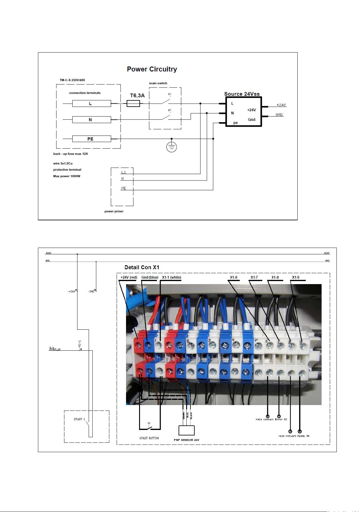
7.1 Introduction
The AG3000 applicator can be integrated in any hard- and software environment as long as the
GoDEX ZX1X00i printer is compatible with that environment as well. However, the communication
lines between the printer and any auxiliary system and between the applicator and such system are
fully separated. Also the kind of information which is exchanged differs:
1) The printer will receive print data (content and settings) from the system through one or more of
its interfaces and can send certain status and error data via the same interfaces. The
communication can take place in various printer languages, the commands being generated by
drivers, label software or the auxiliary system itself. See the printer documentation for detailed
information.
2) The applicator control unit will receive start signals from the auxiliary system and can report
certain status and error signals to that system
A schematic depiction of an AG3000 integrated in a higher control system (e.g. an ERP system) is
given in picture1. The chosen Ethernet is just a random example of how data can be exchanged
between printer and such auxiliary system.
We will explain now how to connect the AG3000 control unit to the most common kinds of these
auxiliary systems, starting with the auxiliary system as a triggering device.
Picture 1: communication between printer, applicator and system
Pic. 1
40
Page 41

7.2 Triggering devices – input signals
The triggering device can be a manual start button, a sensor on a conveyor line, a switch which
is automatically activated when a product is placed onto it, an external PLC built in a robot, a PLC
ultimately controlled by an ERP system, et cetera.
Picture 1: incoming start impulses & outgoing signals
Pic. 1
• Connect +24V red (leftmost) and X1-1 and include a switch or relay in this circuit. This can be
done with any kind of switch or relay. By closing this circuit, you trigger the applicator to start a
print & apply cycle. If the AG3000 is controlled by an external system (e.g. an intermittent
product forwarding system) a controller in that system can close this circuit and trigger the
applicator.
• In case a PNP sensor is used you connect the sensor wires as follows: BROWN to +24V (leftmost
connector), BLUE to Ground (second connector from the left), BLACK to X1-1
7.3 Outgoing signals
X1-6/X1-7 and X1-8/X1-9 form relay controlled switches.
In case of an application time out or printer error, switch X1-6/X1-7 will be closed (ON). If the
AG3000T is ready for the next print & apply cycle switch X1-8/X1-9 will be closed (ON). See both
picture 1 on this page and picture 1 on the previous page for a visualization.
Hence, by creating an electrical circuit over X1-6/X1-7 which is connected to a controller (e.g. a
PLC) on the side of the auxiliary system, that system will know when there is an error and can be
programmed to react in any desirable way (e.g. stop forwarding products, start a warning light).
Hence, by creating an electrical circuit over X1-8/X1-9 which is connected to a controller (e.g. a
PLC) on the sid e of the auxiliary system, that system will know the next product can be labeled.
Such system can be programmed to react in any desirable way (e.g. placing the next product
under the applicator).
41
Page 42

8 Options
Item Number
Description
Lead Time
Integration
AG-3000-HEA060
applicator head 60mm x 60mm
stock item
n.a.
AG-3000-HEA100
applicator head 60mm x 60mm
stock item
n.a.
AG-3000-HEADIV
custom size Applicator Head min. 20x20 max 100x200
2 weeks
low
AG-3000-HEATOU
Applicator Head with Touch Sensor, Suspension,
3 weeks
medium
AG-3000-HEAROL
Applicator Head with Roll-On Unit
stock item
high
AG-3000-HEABLO
Applicator Head with Blow-On Unit, Appr. Sensor,
on request
high
AG-3000-
AG3000 Label Unwinder O/D max 280mm, 40mm
stock item
n.a.
AG-3000-
AG3000 Label Unwinder Core Adapter 76mm
stock item
n.a.
AG-3000-EXHKIT
Set of product table, switch & cable, tubes,
mounting materials
stock item
low
The following AG3000 options are available to suit particular applications. Please be aware
though, that not all are stock items and in some cases a successful implementation may require a
significant amount of experience with the installation of print & apply systems. Therefore, we
mention for each option the complexity of its integration.
Contact us or your GoDEX equipment supplier for more detailed information regarding the options
listed here and in case you are not sure the AG3000T(-LS) is the right solution for your application.
9 Maintenance
AG3000T(-LS) systems require hardly any maintenance, which goes for both the printer and the
applicator components. For applicator maintenance instructions please see the “AG3000
Maintenance & Options Guide” and for printer maintenance instructions the “ZX1200i Service
Manual”. Both are made available to authorized GoDEX dealers.
42
Page 43

10 Wire diagrams
10.1 Power and signals schematic
10.2 Control unit picture
43
Page 44
10.3 Power circuits
10.4 Con ne ct or ra c k - detailed view
44
Page 45
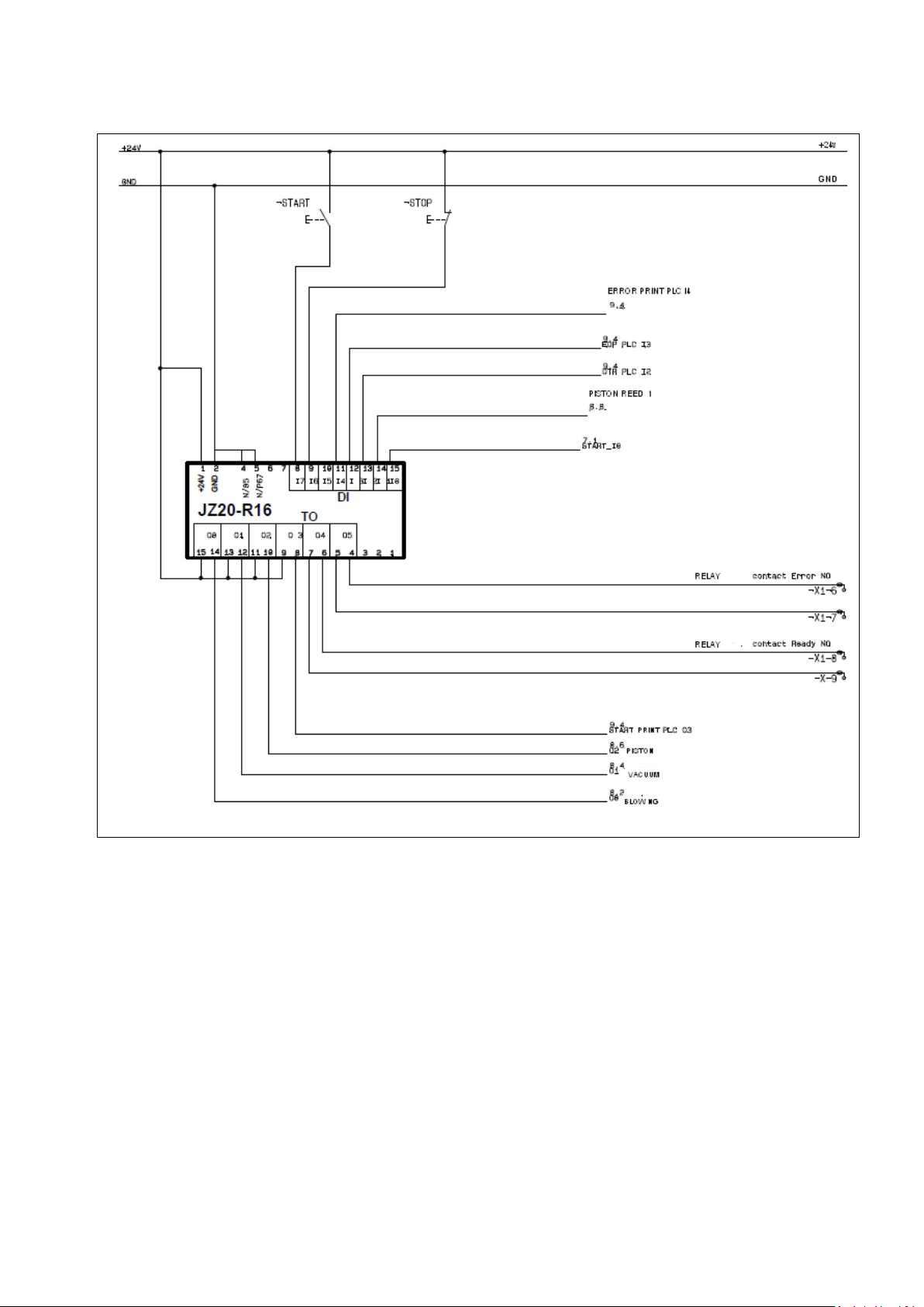
10.5 Connector rack diagram
41
Page 46
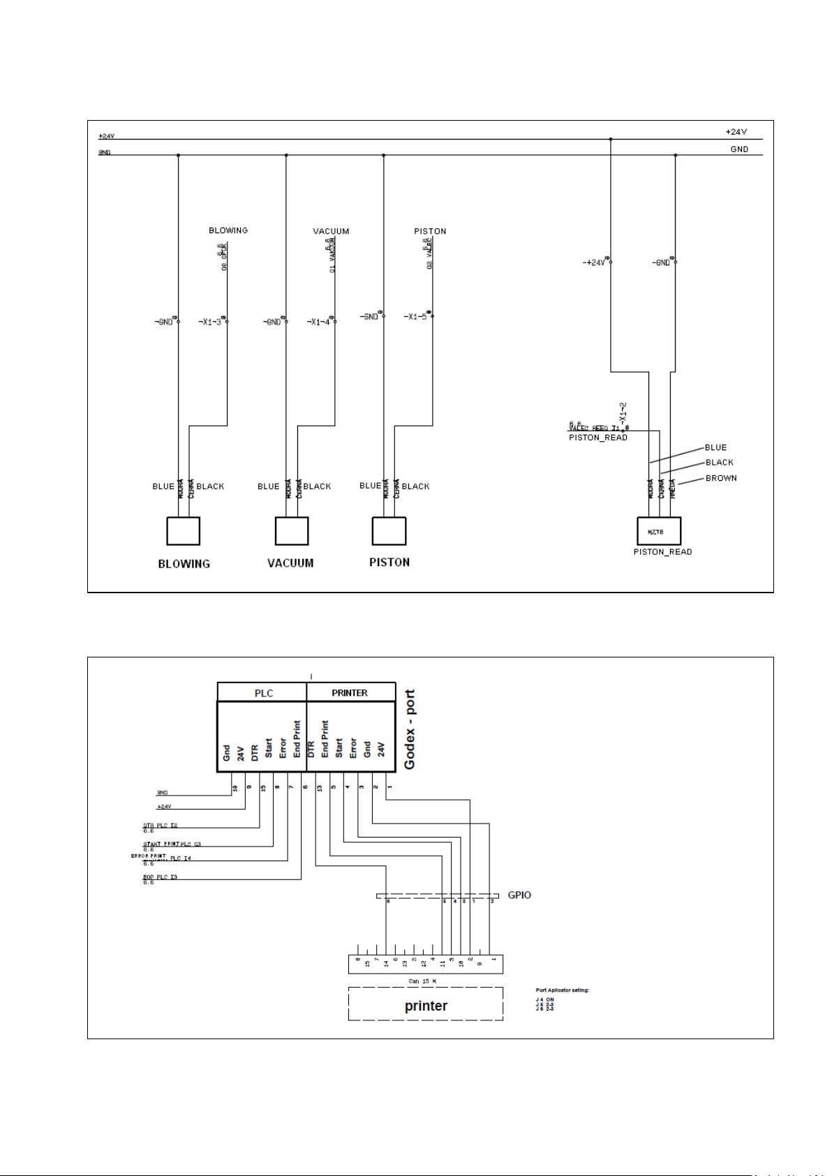
10.6 Electro-pneumatic diagram
10.6 PLC / P rinter applicator port diagram
42
 Loading...