

Page 1
Document release 5.12, September 2017
FM Marin AB
Gobius 4 for Waste Holding Tanks, new version 5.0
Installation Guide
Before you begin
1. Please make sure that no part is missing. 3 sensors, 1 panel,
1 control unit, 1 3M cleaning towel, 1 Velcro fastening for the
control unit, cables, 1 extra sensor tape (3M VHB 4932), warranty
statement and installation instruction on how to attach the
sensors.
2. Determine the best places (¼-, ½- and ¾-level) on your tank to
place the sensors and where to place the panel.
3. Determine the best way to safely access electricity from your
battery 12/24 Volts.
Quick installation
• Attach the sensors to the tank
• Connect all parts
• Start Gobius
• Calibrate
• Test Gobius
• Ready
Attaching the sensors to the tank
Start by reading through the green document before attaching the
sensors to the tank wall. Please visit www.gobius.se for latest news. There
is also Tank Calculator for making it easier for you to calculate the right
levels to put the sensors on the tank wall.
Connect all parts
1. Decide where to place the Gobius panel. It can for instance be
installed in your head/shower or near your waste holding tank.
You may increase the length of the panel cable up to 50 m with a
standard PC network Cat 5 cable.
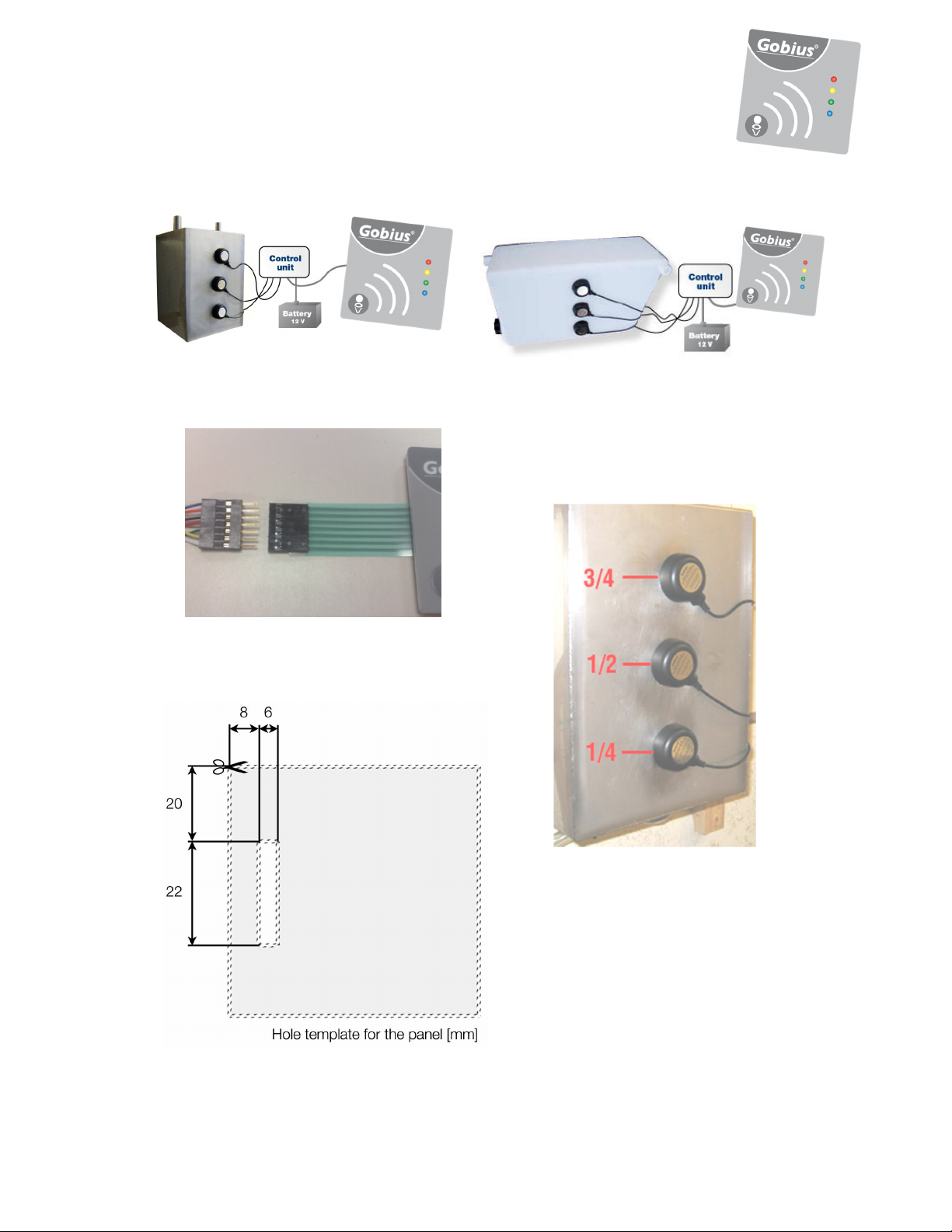
2. We suggest that you make a small rectangle hole where you want
to place the cable from the panel to the control unit. The hole
should be at least 4 mm x 22 mm. Please see the enclosed hole
template at page 5.
3. Use the pre-attached 3M adhesive to fasten the panel to the wall.
4. Connect the panel and the sensors to the control unit. Then
connect the cable to the battery. Make sure to connect + and –
correctly to the battery (+ is white/grey marked and – is black),
Page 2
2
as also described on the control unit. Please see the illustration at
page 5.
5. If you want to connect Gobius to an external display from VDO,
Wema, Faria or others, you should use the analogue output on
the control unit together with the enclosed black cable.
Start Gobius
Connect power source cable to the control unit. Then as Gobius is
starting all lamps are lit, one after another, once. Finally the red, yellow
and green lamps will light saying that you have connected all parts
correct. Now you only have to do the calibration.
Calibrate always with empty tank
No tanks are the same; there are always differences in e.g. material, size,
thickness, construction and age. In order to compensate for these
differences you have to calibrate the system before you can start to use
your Gobius. To start the calibration, start by making sure that your tank
is completely empty. During the measuring you may hear a soft
humming sound from each of the sensors.
Calibration during installation
1. Start by draining the tank
2. Start Gobius and wait for the red, yellow and green lights
3. Press and hold the button until all 4 lights are on
4. Release the button as soon as the lights are on
5. The calibration starts automatically
6. When the blue light is on the calibration is done
Calibration at a later date
1. Start by draining the tank
2. When Gobius is on, press the button and hold
3. Wait until all 4 lights are on
4. Once the lights are on, release the button
5. The calibration starts automatically
6. When the blue light is on the calibration is done
Test Gobius
If possible, please finalize the installation by refilling the tank with liquid
to verify that Gobius works according to your requirements.
2 different ways of turning Gobius on and off
You start Gobius by a quick push on the panel’s button or by
Page 3
3
switching on the power from an external source. A function control on
lamps and sensors is immediately performed. When the control is done
the level is measured and the correct lamp is lit.
You turn off Gobius by a quick push on the button or by switching
off the current from an external source. When Gobius is turned off it
will memorize all settings and the calibration. I.e. you will not need to
redo the calibration due to the power being turned off for a lengthy
period of time.
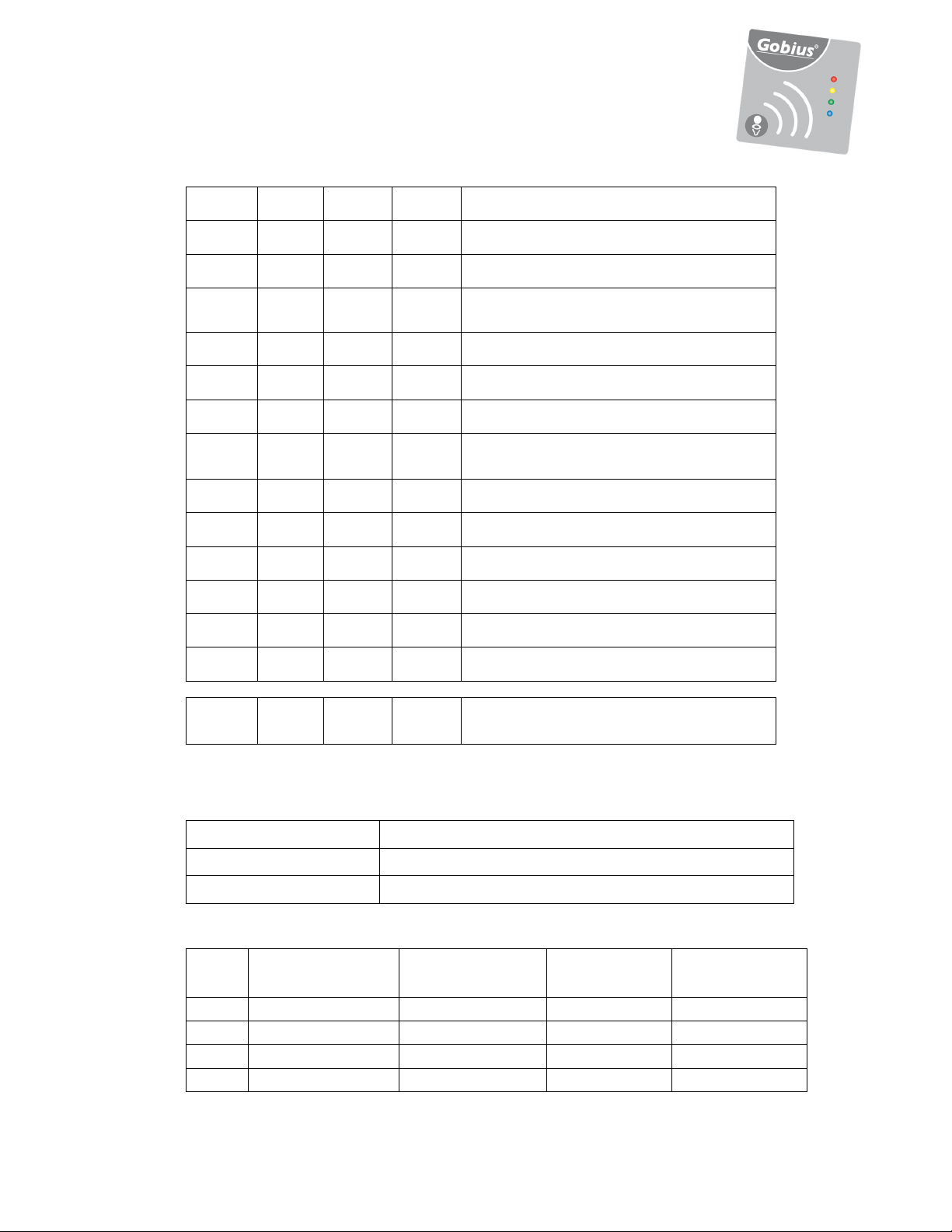
Error
If there should be a problem with one of the sensors, either with the
connection or with the sensor itself, this is illustrated by the responding
lamp on the panel showing a flashing light together with the blue lamp.
For further information, please see the “table of lights” at pages 6 and 7.
You must act on this before you can use Gobius.
If you suspect that the system does not function correctly, please contact our support
service by email, [email protected] or by phone. This support service is free of
charge for products that are registered on our web-site, www.fmmarin.se.
Change of default settings
You will find the default settings of Gobius on page 6 of this
documentation. You change the settings by pressing and holding the
button on the panel. Gobius automatically flicks through the alternatives as
presented in the table on page 6. Release the button when your choice is
shown. Thereby you have made a new setting. Repeat this until you have
made the changes you want.
1. Leave Gobius on
2. With a pen, make notes in the table of the changes you need to do
3. Press and hold the button until the chosen rows’ colours are
shown in the panel
4. Release the button to make your choice a setting
5. Repeat this until you have made the changes you want
By keeping the button pressed until all alternatives are passed, you
may flick through all alternatives without making any change of settings.
A wrongly chosen setting is corrected by repeating the procedure and
thus correcting the setting.
Settings control
Each and every time you turn off Gobius using the button, your
settings are presented by colour combinations on the panel according to
the table on page 6. This will not happen when you turn off Gobius
from an external source.
Page 4

4
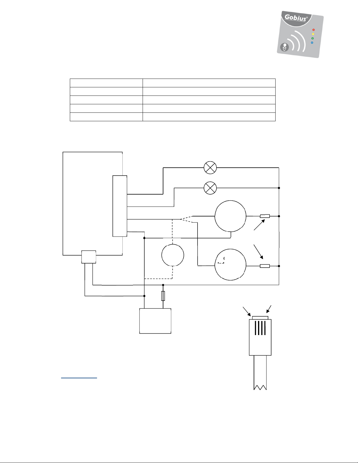
Analog instrument
It is possible to plug in an analog instrument to show the tank level. In
the table on page 6 you will find four alternatives to choose between.
On page 8 you will find an illustration showing how to plug in the
instrument to Gobius’ control unit. The extra black cable is intended for
this purpose. We assume that you have an instrument with cables already
installed in your vessel and that you wish to use this with Gobius.
Extra lamp/buzzer
In addition to the Gobius panel you may want to plug in a lamp or
buzzer to give a warning when the tank is ¾ full. You may also want to
know when the tank is empty. The illustration on page 8 shows how to
plug in this additional surveillance.
Tips
We recommend that you put a layer of Vaseline, which prevents
oxidation, on the plugs that are connected to the control unit. The
electronics of the product are protected from damp. The sensors and the
control unit do not resist water. Please contact FM Marin for advise on
how to make Gobius waterproof. Furthermore, we recommend that you
connect your Gobius via a 500 mA fuse.
The sensors are set to detect liquid levels through tank walls that are of
different materials and thicknesses. If the tank’s wall thickness is
changing over time (e.g. due to possible contamination), you may need
to redo the calibration according to the above instructions.
Gobius Sensor Technology (patented)
Each sensor consists of two active parts; a shaker and an accelerator.
When the shaker creates a vibration in the tank wall, the accelerator
measures the size of the vibration and passes the data on to the control
unit. The control unit then starts to calculate in order to give an exact
estimate of whether the liquid level has passed the sensor or not.
Gobius requires no extra maintenance
The construction of Gobius has many advantages. For instance, since
the sensors are never in direct contact with liquid inside the tank, they
will not become worn out. Another positive aspect of Gobius is its
low electricity consumption, which is less than 50 mA (12 Volts).
Gobius does not require any extra maintenance.
For all these tank materials and tank wall thickness
• Stainless steel, steel, 1 - 3 mm
• Aluminium, 2 – 5 mm
• Polyethylene, 4 – 12 mm
• Fibre Glass, 4 – 8 mm
Page 5
5
System Illustration
Plug from control unit to the panel
Attaching sensors to the tank
(If you connect the panel cable wrong way the
red lamp on the panel will constantly light.
It will not damage the product.)
Page 6
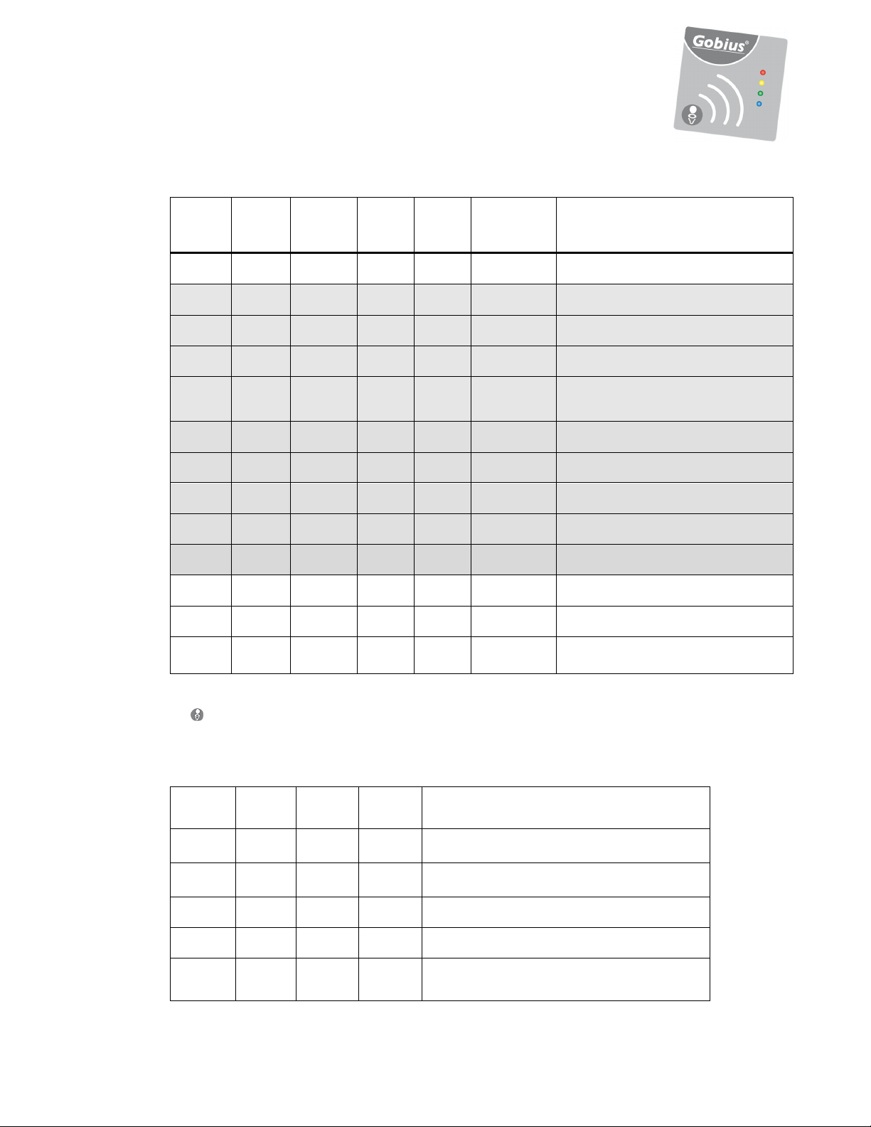
6
Mark
● ● ● ●
○ ● ○ ○
○ ● ○ ●
○ ● ● ○
● ○ ○ ○
● ● ○ ○
● ● ○ ●
● ● ● ○
● ● ● ●
● ○ ● ○
System Reset to default setting
○ ● ○ ●
System Reset Acknowledge
○ ○ ○ ○
The setup mode will be exited
● ● ● ○
○ ○
Test of the ¼
-
sensor
○
○
○ ○
Indicators in Setup Mode
your
choose
D
D
Lamp
Red
○
Lamp
Yellow
●
Lamp
Green
●
Lamp
Blue
●
Duration
in seconds
5 s Calibration
5 s Measurement period 1 minute
5 s Measurement period 5 minutes
5 s Measurement period 10 minutes
5 s
5 s Measurement period 8 hours
5 s Gauge, 4 - 20 mA, Industrial Std
5 s
5 s
5 s Gauge, 0 - 5 Volt DC
5 s
5 s
Description
Measurement period 10 seconds
(installation mode)
Gauge, 10 - 190 Ω, European Std
Gauge, 240 - 33 Ω, US Std
D = Default setting ● = light ○ = no light You change the settings by pressing and holding
the button on the panel. Gobius automatically flicks through the alternatives as presented in the table
above. Release the button when your choice is shown. Thereby you have made a new setting. Repeat
this until you have made the changes you want.
Table of lights – what the lamps on the panel show
Lamp
Red
☼
○
Lamp
Yellow
☼
○
Lamp
Green
☼ ☼
○
Lamp
Blue
☼
☼
☼
Explanation
At delivery
Gobius is not yet calibrated
When starting
Test of the ½-sensor
Test of the 3/4-sensor
When measuring
Tank level 0
N/A
without changing any parameters.
Page 7
7
○ ○
○
○
○ ○
○ ○ ○
After measuring
○ ○ ● ○
○ ● ○ ○
● ○ ○ ○
○ ●☼ ○ ●
●☼ ○ ○ ●
○ ●☼ ●☼ ●
●☼ ○ ●☼ ●
●☼ ●☼ ○ ●
●☼ ●☼ ●☼ ●
☼
☼
○
○
☼
○
○
●
○
☼
Tank level 1/4
Tank level 1/2
Tank level 3/4
●
●
Tank is empty
Tank level 1/4
Tank level 1/2
Tank level 3/4
Sensor errors
1/4-sensor not functioning
1/2-sensor not functioning
3/4-sensor not functioning
1/4-sensor and 1/2-sensor not functioning
1/4-sensor and 3/4-sensor not functioning
1/2-sensor and 3/4-sensor not functioning
☼ ☼ ☼
●
= light
Panel Flashing Codes
Output current/resistance to gauge
Level Industrial standard
0
1/4
1/2
3/4
○
= no light ☼ = flashing light
Permanent on The sensor is not connected, or may be faulty
Fast flashing Illogical result when all 3 sensors are taken together
Slow flashing The sensor may not be properly mounted
4-20 mA current loop
6 mA ± 10% 25 Ω ± 5% 214 Ω ± 5% 1 V ± 5%
10 mA ± 10% 70 Ω ± 5% 150 Ω ± 5% 2 V ± 5%
14 mA ± 10% 120 Ω ± 5% 80 Ω ± 5% 3 V ± 5%
18 mA ± 10% 190 Ω ± 5% 40 Ω ± 5% 4 V ± 5%
No sensors functioning
○
When calibrating
Gobius is calibrating
European standard
10 – 190 Ω
US standard
240 – 33 Ω
Voltage output, 0-5
Volt, 10 kΩ min. load
resistance
Page 8
8
Gauge
1 Yellow
Fuse,
+
-
Gauge
Blue
Black
Optional resistor
4
Red
Black
Volt-
+
Electrical specification
Analogue Instrument outputs: 4-20 mA current loop, 10-190 Ω, 240-33 Ω, 0-5 Volt DC
Supply Voltage: 11 ~ 29 V DC
Supply Current: 200 mA max. (Operating), 50 mA max. (Idle)
Lamp driver outputs: 29 V DC max, 200 mA max
Max. voltage: 29V DC
External interfaces
Control Unit
Analog output
Power input
White/Grey
Black
1
2
3
Yellow
Green
meter
500
mA
Lamp 1, full level
Lamp 2, under ¼ level
Gauge
Eur. or US
standard.
Industry std
4-20 mA
Red
for 24 Volts system
1 Yellow
4 Black
Please note that only one
gauge can be connected
at the same time.
- +
Battery
12/24V
Thank you for choosing Gobius!
Please do not forget to register your Gobius products on
www.fmmarin.se, Products
, in order to receive free technical support
2 Green
3 Red
4 Black
 Loading...