


G690L438T72
GMT G690L438T72, G690L438T71, G690L438T26, G690L438T23, G690L438T22 Datasheet
...
Ver: 1.3
Oct 31, 2002
TEL: 886-3-5788833
http://www.gmt.com.tw
1
G690/G691
Global Mixed-mode Technology Inc.
Microprocessor Reset IC
Features
Precision Monitoring of +3V, +3.3V, and +5V
Power-Supply Voltages
Fully Specified Over Temperature
Available in Three Output Configurations
Push-Pull
RESET Output (G690L)
Push-Pull RESET Output (G690H)
Open-Drain
RESET Output (G691L)
140ms min Power-On Reset Pulse Width
10µA Supply Current
Guaranteed Reset Valid to V
CC
= +1V
Power Supply Transient Immunity
No External Components
3-Pin SOT89, SOT23 and SC70 Packages
Applications
Computers
Controllers
Intelligent Instruments
Critical µP and µC Power Monitoring
Portable / Battery-Powered Equipment
Automotive
General Description
The G690/G691 are microprocessor (µP) supervisory
circuits used to monitor the power supplies in µP and
digital systems. They provide excellent circuit reliability
and low cost by eliminating external components and
adjustments when used with +5V, +3.3V, +3.0V- pow-
ered circuits.
These circuits perform a single function: they assert a
reset signal whenever the V
CC
supply voltage declines
below a preset threshold, keeping it asserted for at
least 140ms after V
CC
has risen above the reset
threshold. Reset thresholds suitable for operation with
a variety of supply voltages are available.
The G691L has an open-drain output stage, while the
G690 have push-pull outputs. The G691L’s open-drain
RESET
output requires a pull-up resistor that can be
connected to a voltage higher than V
CC
. The G690L
have an active-low
RESET
output, while the G690H
has an active-high RESET output. The reset com-
parator is designed to ignore fast transients on V
CC
,
and the outputs are guaranteed to be in the correct
logic state for V
CC
down to 1V.
Low supply current makes the G690/G691 ideal for
use in portable equipment. The G690/G691 are avail-
able in 3-pin SOT89 or SOT23 or SC70 packages.
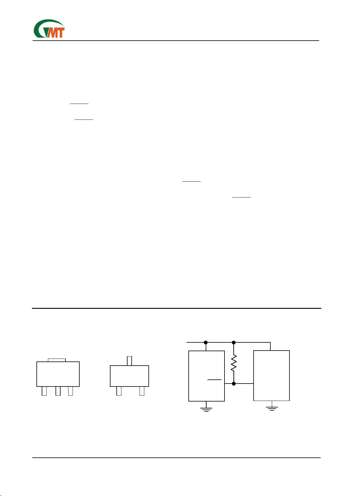
Pin Configuration Typical Application
RESET
INPUT
GND
µP
V
CC
RESET
(RESET)
GND
G690/G691
V
CC
R
PULL-UP
V
CC
*
*G691 ONLY
SOT23/SC70
SOT 89
1
2
12
3
3
RESET
INPUT
GND
µP
V
CC
RESET
(RESET)
GND
G690/G691
V
CC
R
PULL-UP
V
CC
*
*G691 ONLY
SOT23/SC70
SOT 89
1
2
12
3
3
Ver: 1.3
Oct 31, 2002
TEL: 886-3-5788833
http://www.gmt.com.tw
2
G690/G691
Global Mixed-mode Technology Inc.
Ordering Information
PART TEMP. RANGE OUTPUT TYPE
G690LxxxTxx -40°C ~ +105°C Push-Pull Active Low
G690HxxxTxx -40°C ~ +105°C Push-Pull Active High
G691LxxxTxx -40°C ~ +105°C Open-Drain
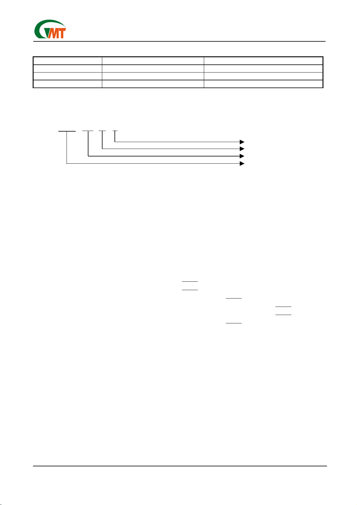
Order Number Identification
G69XX XXX TX X
Pin Option
Package Type
Threshold Voltage Option
Part Number
PART NUMBER
THRESHOLD VOLTAGE OPTION
G690L : Push-Pull Active Low Output * xxx specifies the threshold voltage.
G690H : Push-Pull Active High Output e.g. 263 denotes the 2.63V threshold voltage.
G691L : Open-Drain Output
PACKAGE TYPE PIN OPTION
T2 : SOT 89
1 2 3
T7 : SOT 23
1 :
RESET
GND
V
CC
T9 : SC 70
2 :
RESET
V
CC
GND
3 : GND
RESET
V
CC
4 : GND V
CC
RESET
5 : V
CC
GND
RESET
6 : V
CC
RESET
GND
*RESET for G690H
Ver: 1.3
Oct 31, 2002
TEL: 886-3-5788833
http://www.gmt.com.tw
3
G690/G691
Global Mixed-mode Technology Inc.
Absolute Maximum Ratings
Terminal Voltage (with respect to GND)
V
CC
.……………………………..…….…….-0.3V to +6.0V
RESET,
RESET (push-pull)....…....-0.3V to (V
CC
+ 0.3V)
RESET (open drain)...….......................-0.3V to +6.0V
Input Current, V
CC
............................….................20mA
Output Current, RESET,
RESET ........................20mA
Continuous Power Dissipation (T
A
= +70°C)
3-Pin SOT89……………………………………….500mW
3-Pin SOT23 (derate 4mW/°C above +70°C)….320mW
3-Pin SC70 (derate 2.17mW/°C above +70°C)..174mW
Operating Temperature Range …........-40°C to +105°C
Storage Temperature Range..….….….-65°C to +150°C
Lead Temperature (soldering, 10s) ..…....…......+300°C
Stresses beyond those listed under “Absolute Maximum Ratings” may cause permanent damage to the device. These are stress rat-
ings only, and functional operation of the device at these or any other conditions beyond those indicated in the operational sections of
the specifications is not implied. Exposure to absolute maximum rating conditions for extended periods may affect device reliability.
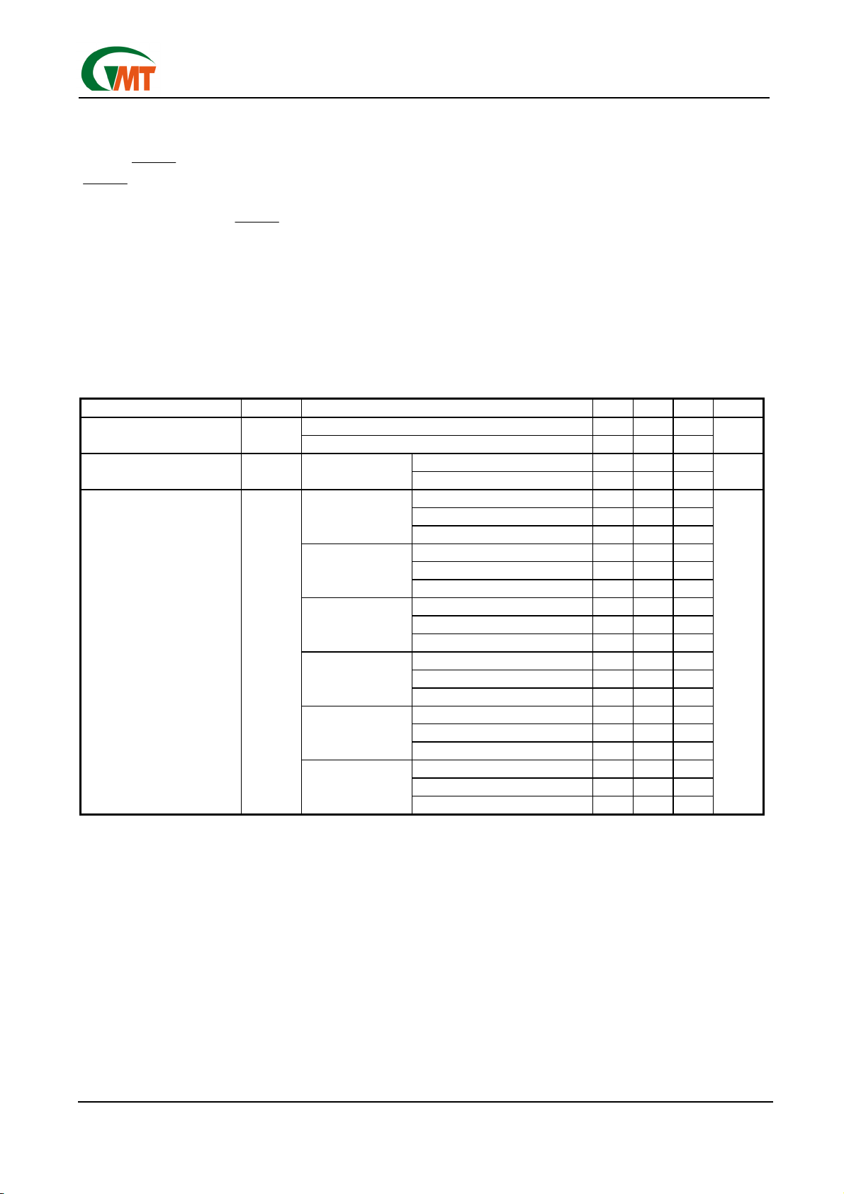
Electrical Characteristics
(V
CC
= full range, T
A
= -40°C to +105°C, unless otherwise noted. Typical values are at T
A
= +25°C, V
CC
= 5V
for 463/438/400 versions, V
CC
= 3.3V for 308/293 versions, and V
CC
= 3V for 263 version.) (Note 1)
PARAMETER SYMBOL CONDITION MIN TYP MAX UNITS
T
A
= 0°C +70°C 1.0 5.5
V
CC
Range
T
A
= -40°C +105°C 1.2 5.5
V
V
CC
<5.5V, G69_ _463/438/400_ 22 30
Supply Current (SOT23) I
CC
T
A
= -40°C +105°C
V
CC
<3.6V, G69_ _308/293/263_ 10 23
µA
T
A
= +25°C 4.56 4.63 4.70
T
A
= -40°C to +85°C 4.50 4.75
G69_ _463_
T
A
= +85°C to +105°C 4.40 4.86
T
A
= +25°C 4.31 4.38 4.45
T
A
= -40°C to +85°C 4.25 4.50
G69_ _438_
T
A
= +85°C to +105°C 4.16 4.56
T
A
= +25°C 3.93 4.00 4.06
T
A
= -40°C to +85°C 3.89 4.10
G69_ _400_
T
A
= +85°C to +105°C 3.80 4.20
T
A
= +25°C 3.04 3.08 3.11
T
A
= -40°C to +85°C 3.00 3.15
G69_ _308_
T
A
= +85°C to +105°C 2.92 3.23
T
A
= +25°C 2.89 2.93 2.96
T
A
= -40°C to +85°C 2.85 3.00
G69_ _293_
T
A
= +85°C to +105°C 2.78 3.08
T
A
= +25°C 2.59 2.63 2.66
T
A
= -40°C to +85°C 2.55 2.70
Reset Threshold V
TH
G69_ _263_
T
A
= +85°C to +105°C 2.50 2.76
V
Ver: 1.3
Oct 31, 2002
TEL: 886-3-5788833
http://www.gmt.com.tw
4
G690/G691
Global Mixed-mode Technology Inc.
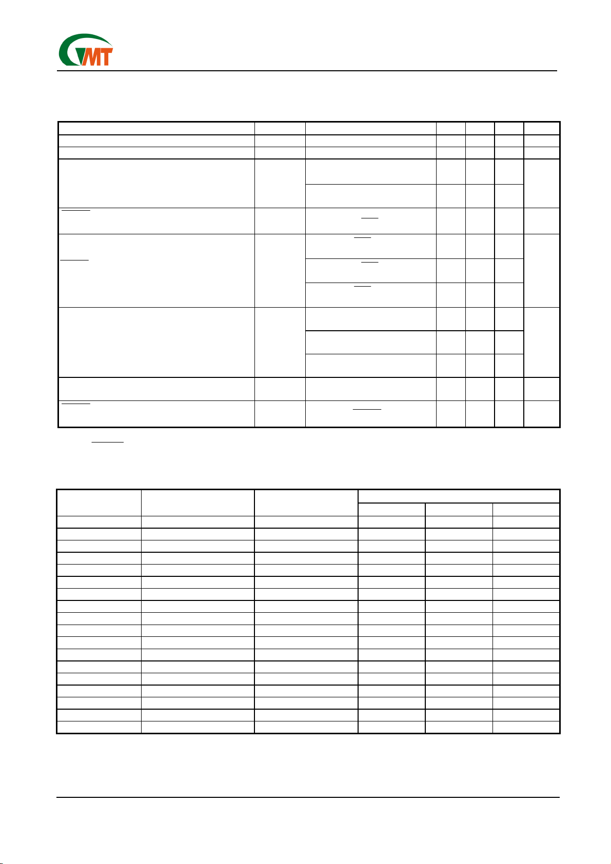
Electrical Characteristics
(Continued)
(V
CC
= full range, T
A
= -40°C to +105°C, unless otherwise noted. Typical values are at T
A
= +25°C, V
CC
= 5V
for 463/438/400 versions, V
CC
= 3.3V for 308/293 versions, and V
CC
= 3V for 263 version.) (Note 1)
PARAMETER SYMBOL CONDITION MIN TYP MAX UNITS
Reset Threshold Tempco 40 ppm/°C
V
CC
to Reset Delay (Note 2) V
CC
= V
TH
to (V
TH
– 100mV) 7 µs
V
CC
= V
TH
max,
G69_ _ 463/438/400
280 640
Reset Active Timeout Period
V
CC
= V
TH
max,
G69_ _308/293/263
140 550
ms
RESET
Output Current Low (push-pull active low,
and open-drain active-low, G690L and G691L)
I
OL
V
CC
= 2.5V, V
RESET
= 0.5V
8 mA
V
CC
= 5V, V
RESET
= 4.5V,
G690L463/438/400
4.5
V
CC
= 3.3V, V
RESET
= 2.8V,
G690L308/293
3
RESET
Output Current High (push-pull active
low, G690L)
I
OH
V
CC
= 3V, V
RESET
= 2.5V,
G690L263
2
mA
V
CC
= 5V, V
RESET
= 0.5V,
G690H463/438/400
16
V
CC
= 3.3V, V
RESET
= 0.5V,
G690H308/293
12
RESET Output Current Low (push-pull active
high, G690H)
I
OL
V
CC
= 3V, V
RESET
= 0.5V,
G690H263
10
mA
RESET Output Current High (push-pull active
high, G690H)
I
OH
V
CC
= 2.5V, V
RESET
= 2V 2 mA
RESET
Open-Drain Output Leakage Current
(G691L)
V
CC
> V
TH
,
RESET
deasserted
1 µA
Note 1: Production testing done at T
A
= +25°C; limits over temperature guaranteed by design.
Note 2:
RESET output is for G690L/G691L; While RESET output is for G690H.
Selector Guide
TOP MARK
PART/SUFFIX RESET THRESHOLD (V) OUTPUT TYPE
SOT 89 SOT 23 SC70
G691L463Tx1 4.63 Open-Drain 689Fx 689Fx 689Fx
G691L438Tx1 4.38 Open-Drain 689Ex 689Ex 689Ex
G691L400Tx1 4.00 Open-Drain 689Dx 689Dx 689Dx
G691L308Tx1 3.08 Open-Drain 689Cx 689Cx 689Cx
G691L293Tx1 2.93 Open-Drain 689Bx 689Bx 689Bx
G691L263Tx1 2.63 Open-Drain 689Ax 689Ax 689Ax
G690H463Tx1 4.63 Push-Pull RESET 688Lx 688Lx 688Lx
G690H438Tx1 4.38 Push-Pull RESET 688Kx 688Kx 688Kx
G690H400Tx1 4.00 Push-Pull RESET 688Jx 688Jx 688Jx
G690H308Tx1 3.08 Push-Pull RESET 688Ix 688Ix 688Ix
G690H293Tx1 2.93 Push-Pull RESET 688Hx 688Hx 688Hx
G690H263Tx1 2.63 Push-Pull RESET 688Gx 688Gx 688Gx
G690L463Tx1 4.63 Push-Pull 688Fx 688Fx 688Fx
G690L438Tx1 4.38 Push-Pull 688Ex 688Ex 688Ex
G690L400Tx1 4.00 Push-Pull 688Dx 688Dx 688Dx
G690L308Tx1 3.08 Push-Pull 688Cx 688Cx 688Cx
G690L293Tx1 2.93 Push-Pull 688Bx 688Bx 688Bx
G690L263Tx1 2.63 Push-Pull 688Ax 688Ax 688Ax
Note: T2: SOT89; T7: SOT23; T9: SC70
 Loading...