

Page 1
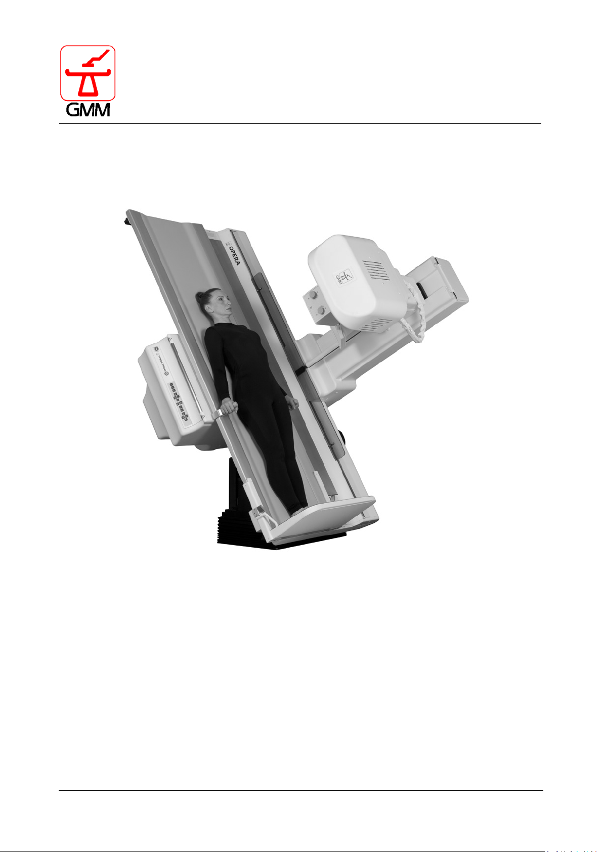
OPERA T
OPERATOR'S MANUAL
OPERA T - OPERATOR'S MANUAL CODE 62235 - REVISION 13
Page 2

BLANK PAGE
OPERA T - OPERATOR'S MANUAL CODE 62235 - REVISION 13
Page 3
R/F Remote Controlled Table
Rev.
Date
Notes
01
May 2005
New version
02
July 2005
Added T30 section – added labels section / position label
Updated planned maintenance table
03
October 2005
Changed identification labels position picture-added new equipment identification labels
03
November 2005
Changed labels
04
November 2005
Added Peristepping (angiography/phlebography stepping) function to push button (27) and
(28), added function Led 10
05
February 2006
Added Periscanning function – push button (26) – updated maintenance schedule
05
July 2006
Corrigenda for push buttons (22) (29)
06
May 2007
Added warning symbol about fingers squashing, added section : insert the X-ray cassette in
the table cassette holder
07
November 2007
Updated console push buttons (22/63/64/65), updated the infotec
08
January 2008
Updated collimator section/collimator extra focal collimator radiations/added section setting
the patient free from collimator
09
February 2008
Replaced the section setting: “patient free from collimator” with new section “Manually
remove the compressor”.
Paragraph 1.2 “Symbols of advice positioned on the equipment” has been completed, by
and of chapter and paragraph numbering.
11
February 2011
New error code 165 entry following positioner software upgrade from V1.6 to V1.6A.
Global revision to update all chapters.
60601-2-54, IEC 60601-1-3.
Additions and update of the following sections: applicable standards, labelling, symbols,
function.
OPERA T
Manufacturer: GENERAL MEDICAL MERATE S.p.A.
Via Partigiani, 25
24068 Seriate (BG) – Italy
Tel. +39 035 45 25 311
Fax +39 035 29 77 87 / 29 95 37
www.gmmspa.com - [email protected]
The original version of this publication was drafted in Italian and will be referred to for any controversy
regarding interpretation of the corresponding versions, translated into several foreign languages.
The contents of this publication may not be reproduced in any manner with any electronic or mechanical
means. It cannot be distributed in any manner without written authorization issued by the manufacturer.
The manufacturer reserves the right to modify/update this document without notice.
REVISION HISTORY
adding 3 additional symbols. In the paragraph 22.1 “Mains supply”, the current absorption
10 July 2009
12 April 2014
13 August 2020
value has been changed from 15A to 20A.
Chapter 20 “Functioning and safety checks” has been revised. General revision of the index,
Modifications and additions for compliance with regulations IEC 60601-1 3rd edition, IEC
accessories, intended use, dimension drawings, environmental conditions data. Dual Energy
OPERA T - OPERATOR'S MANUAL CODE 62235 - REVISION 13
Page 4

BLANK PAGE
OPERA T - OPERATOR'S MANUAL CODE 62235 - REVISION 13
Page 5

OPERATOR'S MANUAL OPERA T
August 2020
Page 1/135
GENERAL MEDICAL MERATE S.P.A. CODE 62235 - REVISION 13
TABLE OF CONTENTS
1. GENERAL NOTES .......................................................................................................... 7
1.1. Typographic conventions .................................................................................................................. 8
1.2. Warning symbols on the equipment ................................................................................................ 9
1.3. Functioning supplementary symbols ............................................................................................. 10
1.4. Applicable Standards and compliance ............................................................................................ 11
1.5. Classification (IEC 60601-1) ............................................................................................................ 11
1.6. Electromagnetic compatibility (EMC) ............................................................................................. 12
2. GENERAL DESCRIPTION .............................................................................................. 15
2.1. Intended use ................................................................................................................................... 15
2.2. OPERA T range ................................................................................................................................ 16
2.3. Components and configuration ...................................................................................................... 17
2.3.1. Image receptors ....................................................................................................................... 17
2.3.1.1. Spot Film Device and cassette division program ..................................................................... 17
2.3.1.2. Image Intensifier and TV chain................................................................................................. 18
2.3.1.3. DR flat panel detector .............................................................................................................. 19
2.3.1.4. R&F flat panel detector ............................................................................................................ 19
2.3.2. Collimator ................................................................................................................................. 19
2.3.3. Compressor .............................................................................................................................. 19
2.3.4. Grid ........................................................................................................................................... 19
2.3.5. Control console ........................................................................................................................ 20
2.4. Performance ................................................................................................................................... 21
2.4.1. Tilting ........................................................................................................................................ 21
2.4.2. Tabletop ................................................................................................................................... 21
2.4.3. X-ray tube stand ....................................................................................................................... 21
2.4.4. Linear tomography ................................................................................................................... 22
2.5. Technical features........................................................................................................................... 23
2.6. Dimension drawings ....................................................................................................................... 26
2.7. Diagnostic room: typical layout ...................................................................................................... 39
3. USER INTERFACE GENERAL DESCRIPTION ................................................................... 40
4. EQUIPMENT STARTUP PROCEDURE AND “MOVEMENT ENABLE” CONTROL ............... 42
4.1. Equipment startup procedure ........................................................................................................ 42
4.2. “Movement enable” control........................................................................................................... 42
5. COMMAND FUNCTIONS OF THE MAIN CONTROL CONSOLE ....................................... 43
5.1. Selecting the image intensifier or RF detector magnification factor ............................................. 44
5.1.1. Selecting the I.I. magnification factor ...................................................................................... 44
5.1.2. Selecting the RF detector magnification factor ....................................................................... 44
5.2. Selecting the layer height ............................................................................................................... 44
5.3. Tomographic functions ................................................................................................................... 45
5.4. Operating mode selector/display ................................................................................................... 45
5.5. Switching the X-ray room light ON or spot film device programme progress ............................... 46
Page 6

OPERATOR'S MANUAL OPERA T
August 2020
Page 2/135
GENERAL MEDICAL MERATE S.P.A. CODE 62235 - REVISION 13
5.5.1. Switching the X-ray room light ON .......................................................................................... 46
5.5.2. Spot film device programme progress .................................................................................... 46
5.6. Emergency Stop push button ........................................................................................................ 46
5.7. Fluoroscopy dose ........................................................................................................................... 47
5.8. Registration frequency or image review function ......................................................................... 47
5.9. Angiographic exercise .................................................................................................................... 47
5.9.1. Peristepping functions: push-buttons (27) and (28) ............................................................... 48
5.9.2. Periscanning function: push-button (26) ................................................................................ 48
5.10. Stitching ......................................................................................................................................... 49
5.11. Automatic sequences during tomography .................................................................................... 50
5.12. Grid parking ................................................................................................................................... 50
5.13. Mixed programming ...................................................................................................................... 50
5.14. Rapid spot filming .......................................................................................................................... 51
5.15. Pulsed fluoroscopy ......................................................................................................................... 51
5.16. Monitor image inversion ............................................................................................................... 51
5.17. Focal distance selector .................................................................................................................. 52
5.18. Selecting automatic exposure or automatic filter area ................................................................. 53
1.1.1. Exposure area selector ............................................................................................................ 53
5.18.1. Filter selector........................................................................................................................... 53
5.19. Size division selector ...................................................................................................................... 53
5.20. Collimator lamp ............................................................................................................................. 55
5.21. Iris diaphragms .............................................................................................................................. 55
5.22. Image intensifier elevation ............................................................................................................ 55
5.23. Collimation mode selector ............................................................................................................. 56
5.23.1. Automatic collimation (Push-button 53 enabled – LED ON) ................................................... 57
5.23.2. Semi-automatic collimation (Push-button 53 enabled – LED flashing)................................... 58
5.23.3. Bucky Mode (Push-button 54 enabled – LED ON) .................................................................. 62
5.24. Stop in the horizontal position ...................................................................................................... 62
5.25. Stand vertical position ................................................................................................................... 62
5.26. Tabletop longitudinal displacement .............................................................................................. 63
5.27. Cassette holder IN-OUT ................................................................................................................. 63
5.28. Diaphragm collimation .................................................................................................................. 64
5.29. Compressor .................................................................................................................................... 64
5.30. Tabletop elevation and tilting ........................................................................................................ 65
5.30.1. Tabletop tilting ........................................................................................................................ 65
5.30.2. Tabletop elevation .................................................................................................................. 65
5.31. X-ray tube stand incidence and footrest rotation ......................................................................... 65
5.31.1. X-ray tube stand incidences .................................................................................................... 66
5.31.2. Footrest rotation ..................................................................................................................... 66
5.32. Control of the patient scanning movements ................................................................................. 66
5.33. X-Ray exposure .............................................................................................................................. 67
5.34. Fluoroscopic exposure ................................................................................................................... 67
6. VISUALIZATION ON THE MAIN CONSOLE DISPLAY ...................................................... 68
6.1. Acquisition frequency or image review function ........................................................................... 68
6.2. Displaying layer height and error codes ........................................................................................ 68
Page 7

OPERATOR'S MANUAL OPERA T
August 2020
Page 3/135
GENERAL MEDICAL MERATE S.P.A. CODE 62235 - REVISION 13
6.2.1. Displaying the layer height ....................................................................................................... 68
6.2.2. Errors codes/ equipment condition ......................................................................................... 68
6.3. Displaying the tilting angle and elevation millimetres ................................................................... 68
6.4. Displaying the incidence angle ....................................................................................................... 69
6.5. Displaying the available exposures ................................................................................................. 69
7. COMMAND FUNCTIONS OF THE SECONDARY CONSOLE (OPTIONAL) .......................... 70
8. FUNCTIONS CONTROLLED FROM THE EXAMINATION TABLE ...................................... 71
8.1. Focal distance selector ................................................................................................................... 71
8.2. Tilting and elevation (optional) of the tabletop ............................................................................. 71
8.3. Oblique incidences ......................................................................................................................... 72
8.4. Longitudinal tabletop displacement (optional) .............................................................................. 72
8.5. Patient scanning ............................................................................................................................. 72
8.6. Cassette holder IN-OUT .................................................................................................................. 72
9. INSERTING THE CASSETTE IN THE SFD ........................................................................ 73
9.1. Selecting conventional radiography ............................................................................................... 73
9.2. Procedure for inserting the cassette .............................................................................................. 73
9.3. Cassette right/left marker (if available) .......................................................................................... 75
10. ON-BOARD CONTROL CONSOLE WITH JOYSTICK (OPTIONAL) ..................................... 76
11. COLLIMATOR ............................................................................................................. 77
11.1. Lighting up of the luminous beam .................................................................................................. 77
11.2. Limiting the X-ray beam field.......................................................................................................... 78
11.3. DFR technique................................................................................................................................. 78
11.4. X-ray cassette technique ................................................................................................................ 78
11.5. X-ray field adjustment for “External Radiographs” ........................................................................ 78
11.6. Collimator manual rotation (90°) - if present ............................................................................... 79
11.7. Collimator type ............................................................................................................................... 79
11.8. X-ray beams extra focal collimator radiations ................................................................................ 80
12. COMPRESSOR ............................................................................................................ 82
12.1. Automatic compressor parking ...................................................................................................... 82
12.2. Compressor display ........................................................................................................................ 82
12.3. Manually removing the compressor ............................................................................................... 83
12.4. Distance scale ................................................................................................................................. 84
12.5. Compressor with interchangeable cones (option) ......................................................................... 84
13. ERROR CODE LIST ...................................................................................................... 85
14. ACCESSORIES ............................................................................................................. 87
14.1. Standard accessories ...................................................................................................................... 87
14.2. Optional accessories ....................................................................................................................... 87
14.3. Using the accessories ...................................................................................................................... 89
Page 8

OPERATOR'S MANUAL OPERA T
August 2020
Page 4/135
GENERAL MEDICAL MERATE S.P.A. CODE 62235 - REVISION 13
14.3.1. Patient support footrest .......................................................................................................... 90
14.3.2. Handgrips ................................................................................................................................ 92
14.3.3. Shoulder-rests ......................................................................................................................... 92
14.3.4. Compression belt .................................................................................................................... 93
14.3.5. Lower limbs support ................................................................................................................ 94
14.3.6. Lateral support for cassette / wifi detector (without grid) ..................................................... 94
14.3.7. Lateral support for wireless detector /CR cassette ................................................................. 95
14.3.8. On-board control console with joystick .................................................................................. 98
14.3.9. Double R/F remote foot pedal ................................................................................................ 99
14.3.10. Cushions for use on the tabletop .......................................................................................... 100
14.3.11. Paediatric cradle .................................................................................................................... 101
14.3.12. Compressor with interchangeable cones .............................................................................. 103
14.3.13. Stitching bar .......................................................................................................................... 104
14.3.14. Removable grid (optional) for detector with manual grids .................................................. 105
15. OPERATION SEQUENCE TO EXECUTE RADIOGRAPHS ON THE TABLE......................... 106
16. APPLICATION EXAMPLES ......................................................................................... 106
16.1. Thorax .......................................................................................................................................... 106
16.2. Digestive and alimentary tract ..................................................................................................... 107
16.3. Cervical column ............................................................................................................................ 107
16.4. Abdominal and lumbar region ..................................................................................................... 108
16.5. Alimentary apparatus of the abdominal region .......................................................................... 108
16.6. Urography and pyelography ........................................................................................................ 108
16.7. Skeleton ....................................................................................................................................... 108
16.8. Arms ............................................................................................................................................. 109
16.9. Hysterosalpingography ................................................................................................................ 109
16.10. Phlebography ............................................................................................................................... 109
17. SAFETY RECOMMENDATIONS .................................................................................. 110
18. PROTECTION MEASURES ......................................................................................... 111
18.1. Safety controls ............................................................................................................................. 111
18.2. Electrical safety ............................................................................................................................ 111
18.3. Safety devices .............................................................................................................................. 111
18.3.1. Dead man controls ................................................................................................................ 111
18.3.2. Low ceiling sensor ................................................................................................................. 112
18.3.3. Emergency stop buttons ....................................................................................................... 112
18.3.4. Movement stop buttons ....................................................................................................... 113
18.3.5. Microswitches ....................................................................................................................... 114
1.1.2. Control software ................................................................................................................... 114
18.4. Dangerous areas .......................................................................................................................... 115
18.4.1. Danger of collision ................................................................................................................. 115
1.1.3. Danger of crushing ................................................................................................................ 115
18.5. Provided gripping points .............................................................................................................. 118
18.6. Patient positioning ....................................................................................................................... 118
18.7. Applied parts ................................................................................................................................ 118
Page 9

OPERATOR'S MANUAL OPERA T
August 2020
Page 5/135
GENERAL MEDICAL MERATE S.P.A. CODE 62235 - REVISION 13
18.8. Measures to be taken to prevent damage to things .................................................................... 118
18.9. Protection against explosions ....................................................................................................... 119
18.10. Protection against radiation ......................................................................................................... 119
18.10.1. Equivalent filtration ............................................................................................................... 122
18.10.2. Dosimetric and quantitative information (IEC 60601-2-54, IEC 60601-1-3) .......................... 123
18.11. Functioning checks on the automatic systems ............................................................................. 127
18.12. Checking automatic collimation ................................................................................................... 127
18.13. Possible connections to other accessories ................................................................................... 127
19. CLEANING AND DISINFECTION ................................................................................. 128
19.1. Cleaning ........................................................................................................................................ 128
19.2. Disinfection ................................................................................................................................... 128
20. FUNCTIONING AND SAFETY CHECKS ........................................................................ 129
20.1. Daily checks .................................................................................................................................. 129
20.2. Six-monthly checks ....................................................................................................................... 129
20.3. Annual maintenance ..................................................................................................................... 129
20.4. Periodical verification of the performance constancy ................................................................. 129
21. LABELLING ............................................................................................................... 130
21.1. Identification and compliance labels ............................................................................................ 130
21.2. Warning lables .............................................................................................................................. 132
22. ENVIRONMENTAL CHARACTERISTICS AND FUNCTIONING LIMITS ............................. 133
22.1. Mains supply ................................................................................................................................. 133
23. RISKS RELATED TO WASTE DISPOSAL ....................................................................... 134
Page 10

OPERATOR'S MANUAL OPERA T
August 2020
Page 6/135
GENERAL MEDICAL MERATE S.P.A. CODE 62235 - REVISION 13
BLANK PAGE
Page 11
OPERATOR'S MANUAL OPERA T
August 2020
Page 7/135
Important Note
IMQ S.p.A.
WARNING
Federal law restricts this device to sale by or on the order of a Physician.
GENERAL MEDICAL MERATE S.P.A. CODE 62235 - REVISION 13
1. GENERAL NOTES
X-RAY EQUIPMENT AND DEVICES CAN BE DANGEROUS FOR THE HEALTH OF BOTH PATIENTS AND OPERATORS
UNLESS PROPER SAFETY MEASURES ARE STRICTLY OBSERVED.
Although this equipment was designed and manufactured according to the most up-to-date safety standards,
the source of X-rays is always dangerous when the operator is not properly qualified or trained. Excessive
exposure to X-rays damages the human body.
Therefore, all the necessary precautions must be taken to prevent unauthorized or unskilled personnel from
operating this equipment, thus jeopardizing themselves and other people. Do not use the equipment if you
have not received appropriate training in the correct and safe use of the equipment itself by the manufacturer
or any of his appointed instructor. Before executing any operation, the persons qualified and authorized to
operate this equipment must be informed about the protection and safety measures established by the
International Committee for Radiological Protection, as well as any other relevant national Standards.
For proper use of this equipment, it is necessary that the operator refer preventively and carefully to this
User’s manual. Special attention should be paid to the sections concerning User Interface, Command
Functions, Application Examples, Safety Recommendations and Protection Measures. Incorrect and
inappropriate use of the machine by poorly qualified personnel who are unsuitable and insufficiently
trained can cause fatal accidents.
N.B.
This device is in compliance with the requirements established by the European Directive 2007/47/EC which
amends the Directive 93/42/EEC regarding medical devices, thus it bears the EC mark stating the code number
identifying the notified body responsible for carrying out the procedures foreseen for the compliance
certification.
This is a Class IIb device according to Rule 10 of Annex IX to Directive 93/42/EEC and following amendments
and additions.
The manufacturer declines all responsibility with regard to the proper functioning of the equipment, should
the installation or the maintenance of it be executed by unauthorized personnel.
The X-ray system’s installation instructions are included in a service manual, which is a separate item from the
Operator’s manual.
According to 21 CFR 801.109
Page 12
OPERATOR'S MANUAL OPERA T
August 2020
Page 8/135
Important information
It is advisable that extra attention be paid in reading the topics identified with this symbol.
WARNING
The topics identified with this icon regard aspects of safety for the patient and/or operator.
GENERAL MEDICAL MERATE S.P.A. CODE 62235 - REVISION 13
1.1. Typographic conventions
In order to facilitate the reading of the manual, different styles and types were used.
The text identified by bullets indicates:
Instructions to be executed according to the sequence specified.
The text in italics inside a frame indicates:
Useful supplementary information for the technician.
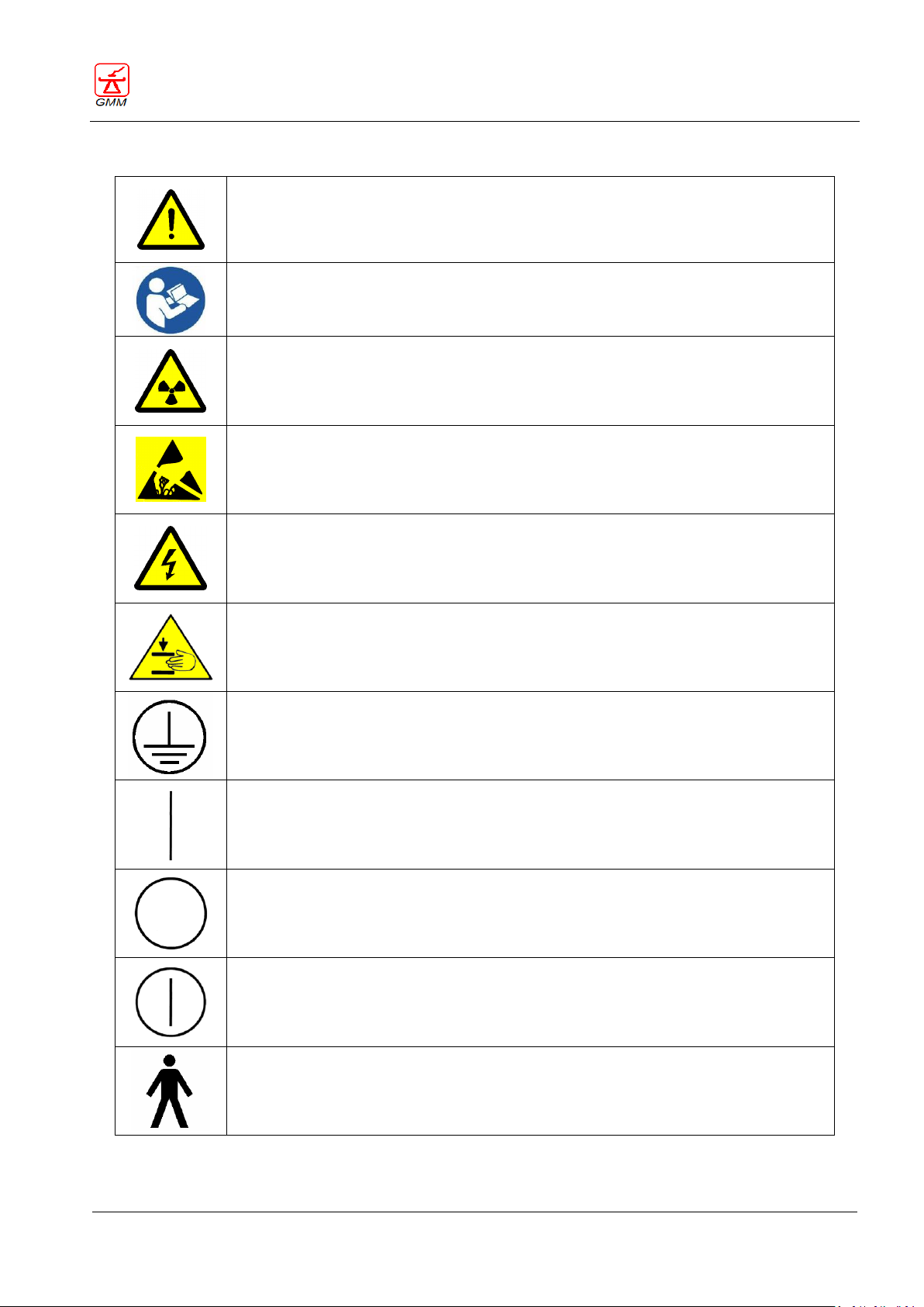
The following icons are also used:
Page 13
OPERATOR'S MANUAL OPERA T
August 2020
Page 9/135
Warning symbol that indicates potential generic danger for the equipment or the
operator. It invites the operator to check the equipment documentation for further
details.
Warning symbol that invites operators to follow the instructions for using the device
on which the symbol itself is applied.
Hazard symbol that indicates X-ray radiation exposure.
Warning symbol that indicates electrical components which are sensitive to
electrostatic discharge.
Warning symbol that indicates live electrical parts with a possible risk of electric
shock.
Warning symbol that indicates that fingers may be crushed.
Symbol of protective earth (ground).
“ON” symbol (power).
“OFF” symbol (power).
“ON” / “OFF” symbol (push-push).
Symbol of applied part B type.
GENERAL MEDICAL MERATE S.P.A. CODE 62235 - REVISION 13
1.2. Warning symbols on the equipment
Page 14
OPERATOR'S MANUAL OPERA T
August 2020
Page 10/135
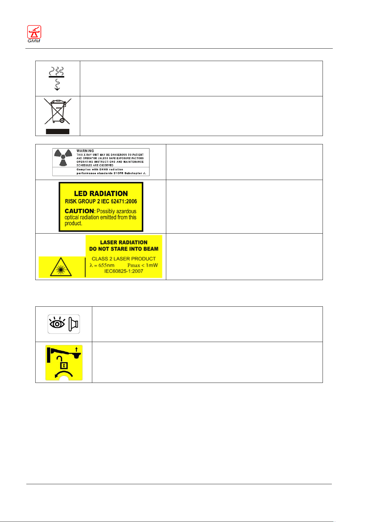
Symbol of filtration.
Symbol that indicates electrical and electronic components which must be collected
separately.
Subchapter J label
LED radiation warning
LASER radiation warning
Fluoroscopy and radiography foot pedal connector fitting
Unlocking of the compressor (if installed)
GENERAL MEDICAL MERATE S.P.A. CODE 62235 - REVISION 13
1.3. Functioning supplementary symbols
Page 15
OPERATOR'S MANUAL OPERA T
August 2020
Page 11/135
Reference
Description
European Directive 2007/47/CE which amends the
Directive 93/42/EEC
Class IIb device according to Rule 10 of Annex IX
Medical Device Directive (EC mark)
IEC 60601-1:2005+A1:2012
General requirements for the basic safety and
essential performance
IEC 60601-1-2:2014
General requirements for the basic safety and
essential performance - Collateral standards:
Electromagnetic compatibility
IEC 60601-1-6:2010+A1:2013
General requirements for the basic safety and
essential performance - Collateral standards:
Usability
IEC 60601-2-54:2009+A1:2015
Particular requirements for the basic safety and
essential performance of X-ray equipment for
radiography and radioscopy
IEC 60601-1-3:2008+A1:2013
General requirements for the basic safety and
essential performance - Collateral Standard:
Radiation protection in diagnostic X-ray
equipment
IEC 62304:2006+A1:2015
Medical device software – Software life-cycle
processes
Type of protection against electric shock
class I equipment
Degree of protection against electric shock
with applied part B type
Degree of protection against seepage of harmful water
ordinary IPX0 type equipment
Functioning mode
continuous functioning with intermittent
loading (standby - exposure)
Equipment not suitable for use in presence of a
flammable anaesthetic mixture with air or with oxygen
or nitrous oxide.
GENERAL MEDICAL MERATE S.P.A. CODE 62235 - REVISION 13
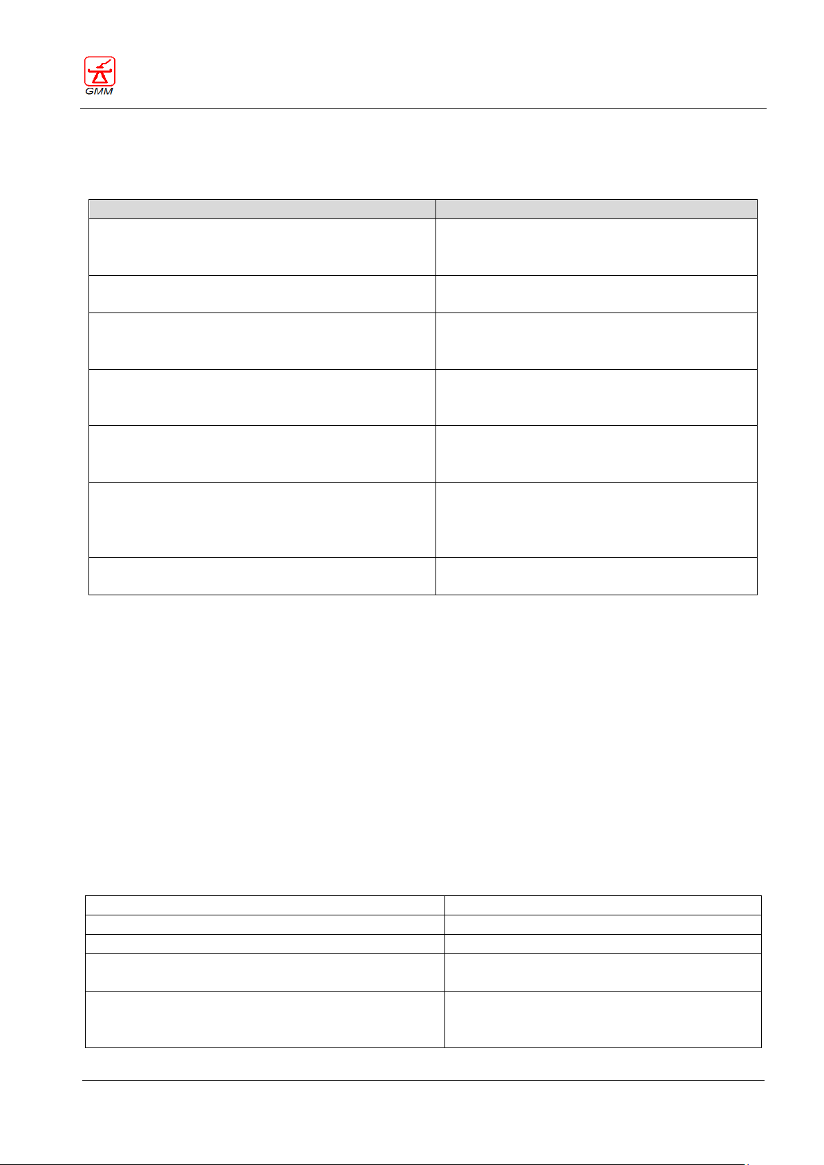
1.4. Applicable Standards and compliance
This OPERA T90 SHARPtable complies with the requirements and design standards of the following directives
concerning electro-medical equipments:
All the medical devices that interface or integrate with the table for system composition, acquired by the
manufacturer or built with OEM for the manufacturer are individually certified, must meet the requirements
of Annex I of the European Directive 2007/47/EC which amends the Directive 93/42/EEC and must comply
with the following standards regarding electro-medical equipments:
X-ray generator IEC 60601-2-54
X-ray radiant components IEC 60601-2-28
Digital system IEC 60601-1
For the north American market:
UL 60601-1 ; CAN/CSA C22,2 No 601.
NOTE: All reference standards are to be considered at the latest revision.
1.5. Classification (IEC 60601-1)
Page 16
OPERATOR'S MANUAL OPERA T
August 2020
Page 12/135
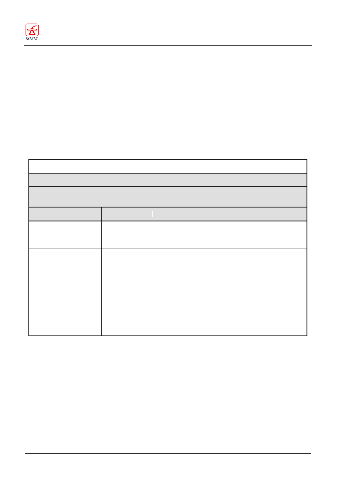
Annex A
Guidance and manufacturer’s declaration – Electromagnetic emissions
The Equipment is suitable for use in the specified electromagnetic environment. The purchaser or user of the
Equipment should assure that it is used in an electromagnetic environment as described below:
Emissions test
Compliance
Electromagnetic Environment
RF emissions
CISPR 11
Group 1
This Equipment uses RF energy only for its internal function.
Therefore, the RF emission is very low and not likely to cause
any interference in nearby electronic equipment.
RF emissions
CISPR 11
Class A
This Equipment is suitable for use in all establishments other
than domestic and those directly connected to the public lowvoltage power supply network that supplies buildings used for
domestic purposes.
Harmonic emissions
IEC 61000-3-2
Not Applicable
Voltage fluctuations/
flicker emissions
IEC 61000-3-3
Not Applicable
GENERAL MEDICAL MERATE S.P.A. CODE 62235 - REVISION 13
1.6. Electromagnetic compatibility (EMC)
In accordance with the intended use, this remote controlled Table complies with the European Directives
concerning Medical Devices. The CE marking affixed to this product signifies this. One of the standards of this
directive defines the allowed levels of electromagnetic emission from this equipment and its required
immunity from the electromagnetic emissions of other devices.
It is not possible, however, to exclude with absolute certainty the possibility that other high frequency
electronic equipment, which is fully compliant to the EMC regulations, will not adversely affect the operation
of this system. If the other equipment has a comparatively high level of transmission power and is in close
proximity to the system, these EMC concerns (the risk of interference) may be more pronounced. It is
therefore recommended that operations with mobile or cordless telephones, microphones and other similar
equipment, such as mobile radio systems, are strictly executed away from the R&F device.
Page 17

OPERATOR'S MANUAL OPERA T
August 2020
Page 13/135
Annex B
Guidance and manufacturer’s declaration – Electromagnetic immunity
The Equipment is suitable for use in the specified electromagnetic environment. The purchaser or user of the Equipment
should assure that it is used in an electromagnetic environment as described below:
Immunity
Test
IEC 60601-1-2
Test level
Compliance
level
Electromagnetic Environment
Electrostatic
discharge (ESD)
IEC 61000-4-2
8 kV contact
2/4/8/15 kV air
IEC 60601-1-2
Test level
Floors should be wood, concrete or ceramic
tile. If floors are covered with synthetic
material, the relative humidity should be at
least 30%.
Radiated
electromagnetic field
IEC 61000-4-3
3 V/m
80 MHz to 2.7 GHz
IEC 60601-1-2
Test level
Portable and mobile RF communications
equipment
should be used no closer to any part of the
Equipment, including cables, than the
recommended separation distance
calculated from the equation
applicable to the frequency of the
transmitter
Recommended separation distance
Electrical fast
transient/burst
IEC 61000-4-4
2 kV for power
supply lines
1 kV for input/output
lines > 3 m
IEC 60601-1-2
Test level
Mains power quality should be that of a
typical commercial or hospital
environment.
Surge
IEC 61000-4-5
0.5/1 kV differential mode
0.5/1/2 kV common mode
IEC 60601-1-2
Test level
Mains power quality should be that of a
typical commercial or hospital
environment.
Conducted RF
IEC 61000-4-6
3 V
150 kHz to 80 MHz
6 V
ISM frequencies
IEC 60601-1-2
Test level
Portable and mobile RF communications
equipment
should be used no closer to any part of the
Equipment, including cables, than the
recommended separation distance
calculated from the equation
applicable to the frequency of the
transmitter
Recommended separation distance
Voltage dips, short
interruptions
and voltage
variations on power
supply input lines
IEC 61000-4-11
0% Un for 0.5 cycles
0 % Un for 1 cycles
70 % Un for 25 cycles
0 % Un for 5 s
IEC 60601-1-2
Test level
Mains power quality should be that of a
typical commercial or hospital
environment. If the user of the Equipment
requires continued operation during power
mains interruptions, it is recommended that
the Equipment be powered from an
uninterruptible power supply or a battery.
Power frequency
(50/60 Hz) magnetic
field
IEC 61000-4-8
30 A/m
IEC 60601-1-2
Test level
Power frequency magnetic fields should be
at levels characteristic of a typical location
in a typical commercial or hospital
environment.
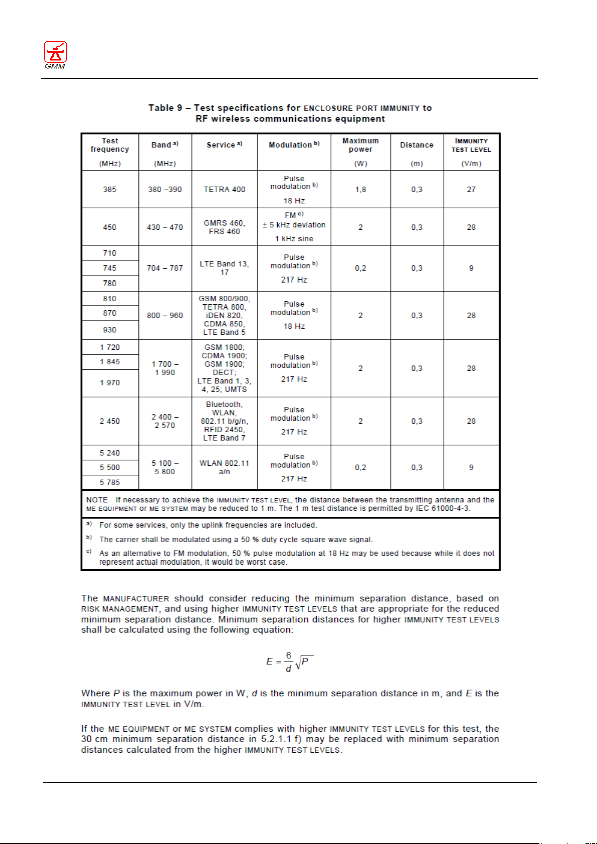
GENERAL MEDICAL MERATE S.P.A. CODE 62235 - REVISION 13
Page 18
OPERATOR'S MANUAL OPERA T
August 2020
Page 14/135
GENERAL MEDICAL MERATE S.P.A. CODE 62235 - REVISION 13
Page 19
OPERATOR'S MANUAL OPERA T
August 2020
Page 15/135
GENERAL MEDICAL MERATE S.P.A. CODE 62235 - REVISION 13
2. GENERAL DESCRIPTION
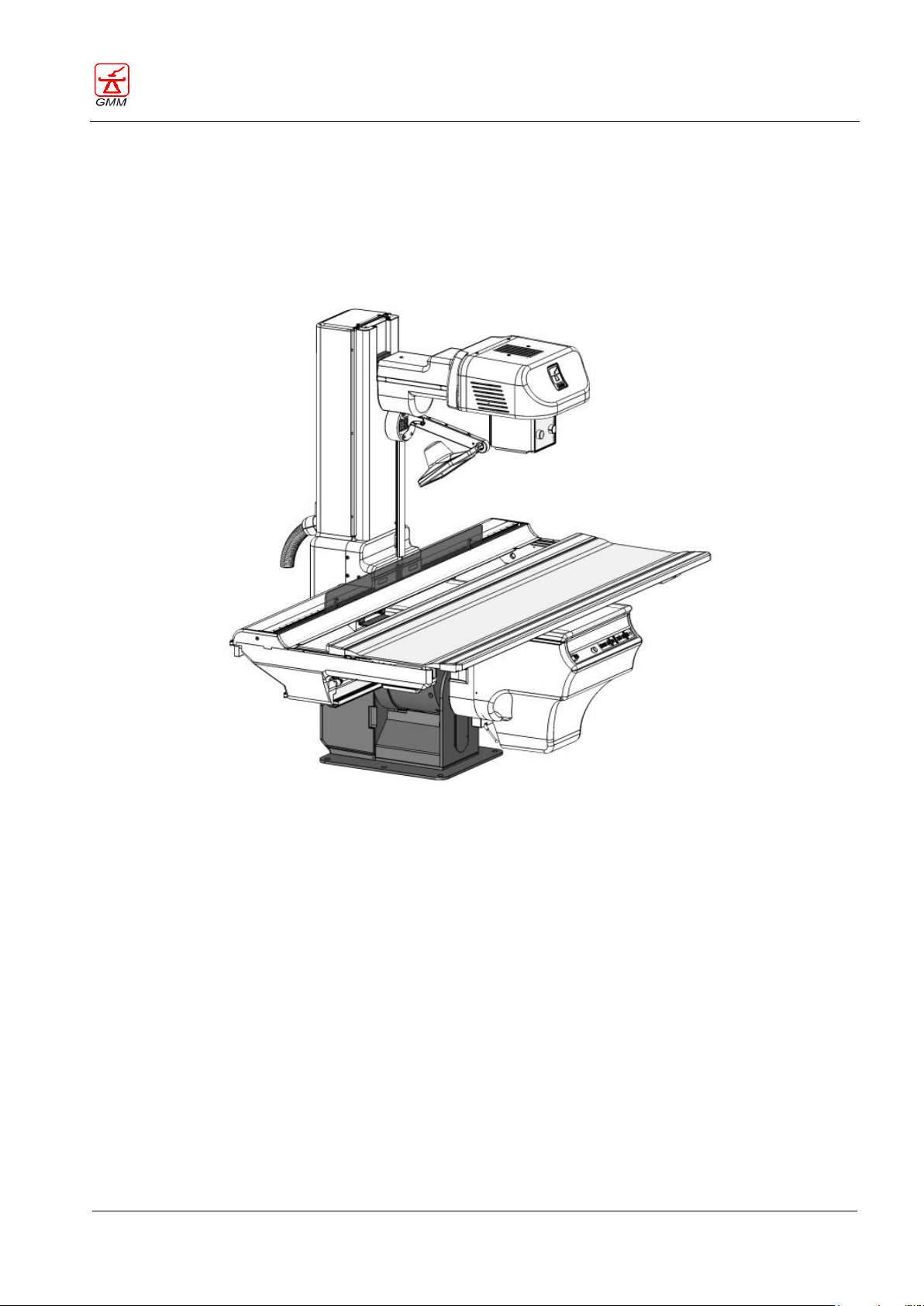
OPERA is a system featured by a high degree of integration including a wide range of remote-controlled
tables, generators and digital imaging systems.
The remote-controlled tables of OPERA T range are backed up by an exclusive and advanced concept and
thanks to the high modularity of their structures they can be configured according to the user's specific needs,
thus ensuring the optimization of the performance-cost ratio.
2.1. Intended use
This equipment is indicated for performing general radiography, fluoroscopy and angiography procedures.
Applications and techniques:
- Gastroenterology
- Skeleton
- Thorax and lungs
- Paediatrics
- Urology and gynaecology
- Emergency/traumatology
- Stitching
- Linear tomography
Only in combination with Opera D4000RF digital system
(for more details, refer to the O-D4000RF user manual)
- Digital angiography
- Tomosynthesis
- Dual Energy
Page 20
OPERATOR'S MANUAL OPERA T
August 2020
Page 16/135
Model
Tilting
Tabletop
height from
floor
Tabletop
length
Maximum focal
distance
(Max SID )
Optional
longitudinal
tabletop movement
O-T30CS/5
-30° +90°
Fixed 86 cm
210 cm
150 cm
+80/-80
O-T30CS/8
-30° +90°
Fixed 86 cm
210 cm
180 cm
+80/-80
O-T30CSX/5
-30° +90°
Fixed 86 cm
240 cm
150 cm
+80/-80
+100/-20
O-T30CSX/8
-30° +90°
Fixed 86 cm
240 cm
180 cm
+80/-80
+100/-20
O-T90CS/5
-90° +90°
Fixed 86 cm
210 cm
150 cm
+80/-80
O-T90CS/8
-90° +90°
Fixed 86 cm
210 cm
180 cm
+80/-80
O-T90CSX/5
-90° +90°
Fixed 86 cm
240 cm
150 cm
+80/-80
+100/-20
O-T90CSX/8
-90° +90°
Fixed 86 cm
240 cm
180 cm
+80/-80
+100/-20
O-T90CE/5
-90° +90°
Variable
76 -100 cm
210 cm
150 cm
+80/-80
O-T90CE/8
-90° +90°
Variable
76 -100 cm
210 cm
180 cm
+80/-80
O-T90CEX/5
-90° +90°
Variable
76 -100 cm
240 cm
150 cm
+80/-80
+100/-20
O-T90CEX/8
-90° +90°
Variable
76 -100 cm
240 cm
180 cm
+80/-80
+100/-20
O-T30CSG
-30° +90°
Fixed 86 cm
210 cm
115 cm (fixed)
---
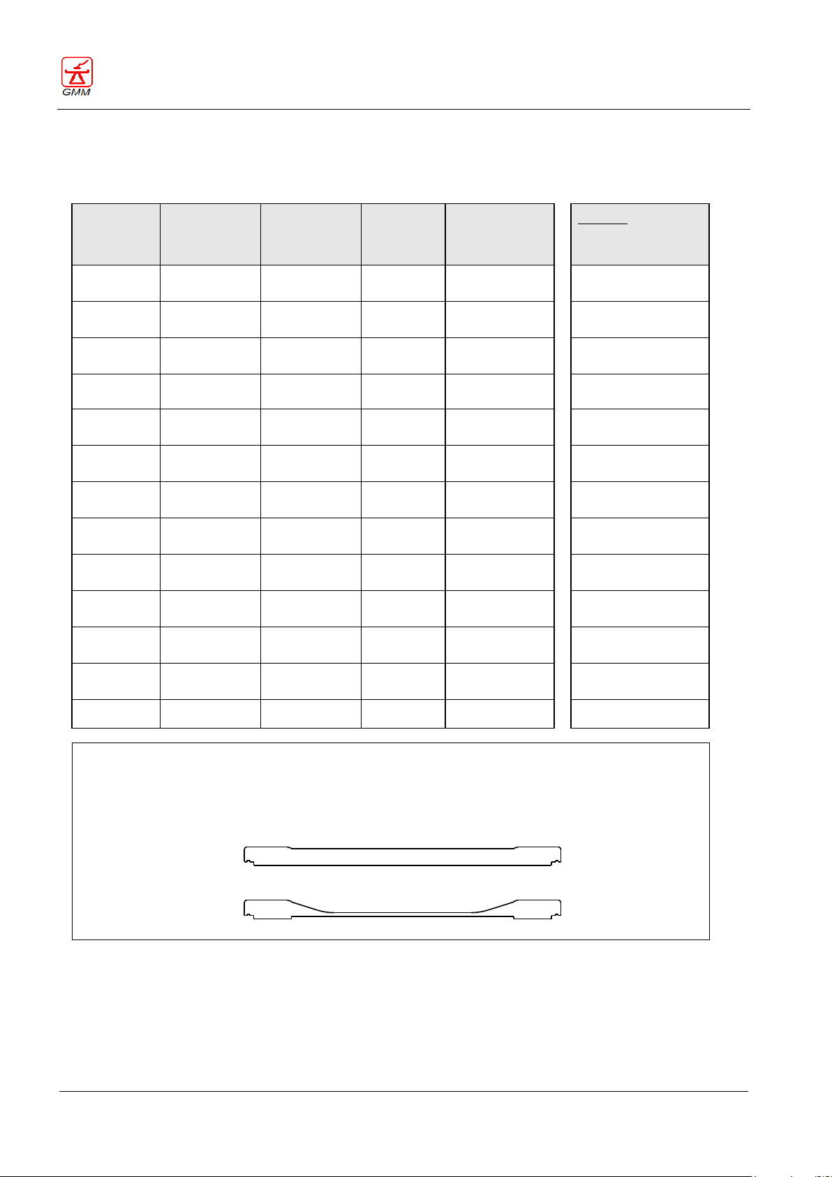
The tabletop is available in carbone fibre or wood stratified version. Both versions can be either
with a flat (A) or concave (B) transversal profile, by simply inverting the tabletop.
The inversion of the tabletop can be executed during the installation or later on by the service
personnel. In addition, a plastic laminate tabletop with flat transversal profile is available.
A
B
Tabletop transversal profile
GENERAL MEDICAL MERATE S.P.A. CODE 62235 - REVISION 13
2.2. OPERA T range
The remote-controlled table can be configured according to the users’ specific needs. See available version
features below.
Page 21
OPERATOR'S MANUAL OPERA T
August 2020
Page 17/135
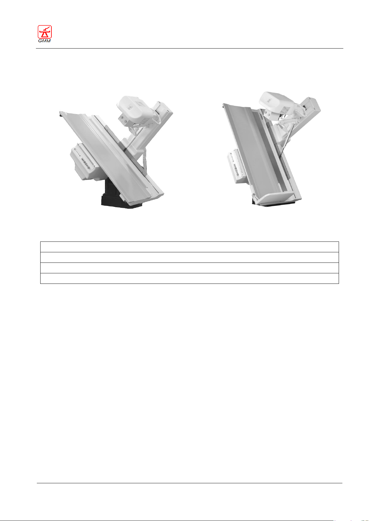
Configuration with SFD and II-CCD or II-CCD and DR flat panel
Configuration with R&F flat panel
Spot Film Device with vertical subdivision + Image Intensifier and TV chain
Spot Film Device with vertical/crossed subdivision + Image Intensifier and TV chain
DR flat panel detector + Image Intensifier and TV chain
R&F flat panel detector
GENERAL MEDICAL MERATE S.P.A. CODE 62235 - REVISION 13
2.3. Components and configuration
OPERA T table versions listed in the previous section can be combined with different system components,
depending on the users’ specific needs.
2.3.1. Image receptors
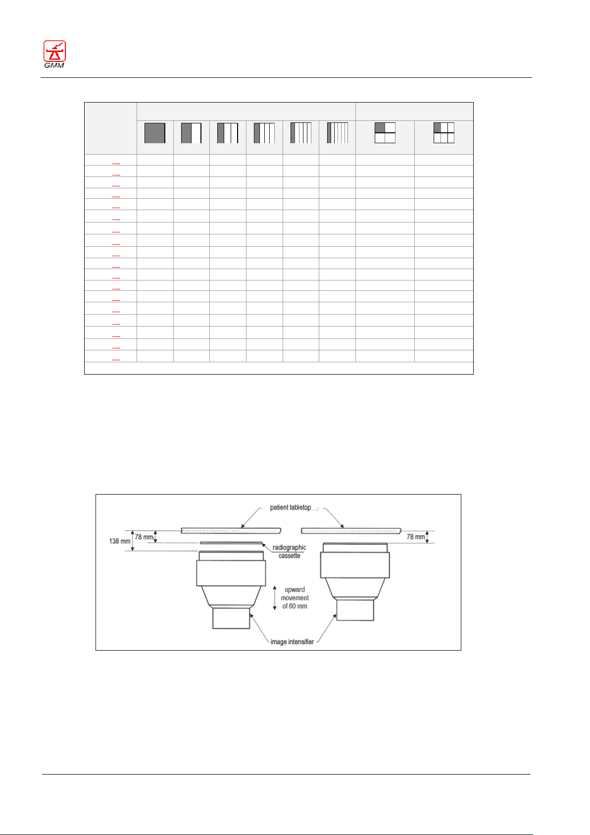
2.3.1.1. Spot Film Device and cassette division program
The SFD is completely automatic and, thanks to its great versatility, can be used with any standard size
cassette from 18x24 to 35x43 cm.
Subdivision :
‐ Vertical division by 2, 3 and 4, for all cassette sizes in both direction.
‐ Vertical division by 5 and 6, for cassette size larger than 24 cm . As option, crossed
division by 4 and 6, for 18x24, 24x24 and 24x30 cm cassettes size.
SFD versatility is even enhanced by the grid retracting capability and by a cassette film marker (right/left - see
section 9.3).
Page 22
OPERATOR'S MANUAL OPERA T
August 2020
Page 18/135
VERTICAL SUBDIVISION
OPTIONAL CROSSED
SUBDIVISION (as alternative)
CASSETTE
SIZE* (cm)
1 2 3 4 5 6 4
6
18X24
〇 〇 〇
〇
〇
〇
24X18
〇 〇 〇
〇
〇
〇
18X43
〇 〇 〇 〇 〇
〇
43X18
〇 〇 〇
〇
20X40
〇 〇 〇 〇 〇
〇
40X20
〇 〇 〇
〇
24X24
〇 〇 〇
〇
〇
〇
24X30
〇 〇 〇 〇 〇 〇 〇
〇
30X24
〇 〇 〇
〇
〇
〇
30X30
〇 〇 〇 〇 〇
〇
30X35
〇 〇 〇 〇 〇
〇
35X30
〇 〇 〇 〇 〇
〇
30X40
〇 〇 〇 〇 〇
〇
40X30
〇 〇 〇 〇 〇
〇
35X35
〇 〇 〇 〇 〇
〇
35X43
〇 〇 〇 〇 〇
〇
43X35
〇 〇 〇 〇 〇
〇
40X40
〇 〇 〇 〇 〇
〇
* Cassette size of reference is underlined
Cassette division program
I.I. elevation system (optional)
GENERAL MEDICAL MERATE S.P.A. CODE 62235 - REVISION 13
2.3.1.2. Image Intensifier and TV chain
OPERA T can be equipped with Image Intensifier from 9" to 16" and high performance TV chains complete of
automatic dose control device. The remote‐controlled table can be configured for the application of digital
imaging systems. A very important aspect is represented by the possibility (as option) of Image Intensifier
elevation, since this allows setting its input surface at the same level of the X‐ray film. This feature ensures
exposure geometry optimization in digital fluoroscopy and fluorography.
Page 23

OPERATOR'S MANUAL OPERA T
August 2020
Page 19/135
Motorized collimator with rectangular field
Motorized collimator with rectangular field and Iris
Motorized collimator with rectangular field, Iris and motorized filters
Motorized collimator with rectangular field and motorized filters
Motorized collimator with rectangular field, Iris and manual filters *
Motorized collimator with rectangular field and manual filters *
* Available in function of the installation Country regulations
GENERAL MEDICAL MERATE S.P.A. CODE 62235 - REVISION 13
2.3.1.3. DR flat panel detector
Instead of the normal film/CR cassette a DR flat panel detector can be used which is available in two versions:
- 35x43 cm useful area ‐ wireless mobile
- 43x43 cm useful area - tethered fixed (with I.I. up to 12”)
The 35x43 cm wireless is a “cassette like” DR flat panel, thus it can be inserted in the SFD like any normal
film/CR cassette.
With a special version of OPERA DFR digital system it is possible to acquire both RF camera images and DR
panel images using one console only.
2.3.1.4. R&F flat panel detector
A full digital solution can be chosen for both fluoroscopic and radiographic imaging. This solution is based on
OPERA D4000RF digital system and PIXIUM RF4343 flat panel detector designed to replace conventional R&F
radio‐diagnostic systems based on conventional film/CR cassette with SFD and fluoroscopy systems with
image intensifier.
2.3.2. Collimator
For further information, see chapter 11.
2.3.3. Compressor
The remote controlled compressor allows an effective though not traumatic palpation; the compression force
can be adjusted up to 200 N.
A special consideration has been devoted to mechanical and electrical safety, as well as safety against wrong
manoeuvres. The compressor has a parking position from which it automatically moves in and out.
An alternative compression system with three interchangeable cones without automatic parking feature is
available, as optional accessory. For further information, see chapter 12.
2.3.4. Grid
Tables with focal distance (SID) up to 150 cm are equipped with a single grid system.
Tables with focal distance (SID) up to 180 cm can be equipped with a dual grid system to ensure optimal
radiological conditions during any exposure. The system will automatically set the proper grid focalization
based on the selected SID. The grid can be automatically parked to ensure low dose in pediatrics applications
and for extremities examinations.
To use the single grid device is however possible on tables with SID up to 180 cm.
In addition, a high focalization grid is also available.
N.B. The dual grid system is not available for SFD version with crossed subdivisions
Page 24
OPERATOR'S MANUAL OPERA T
August 2020
Page 20/135
Single console on stand
Integrated console on stand
Console with touch screen + digital system
Secondary in-room console on trolley
GENERAL MEDICAL MERATE S.P.A. CODE 62235 - REVISION 13
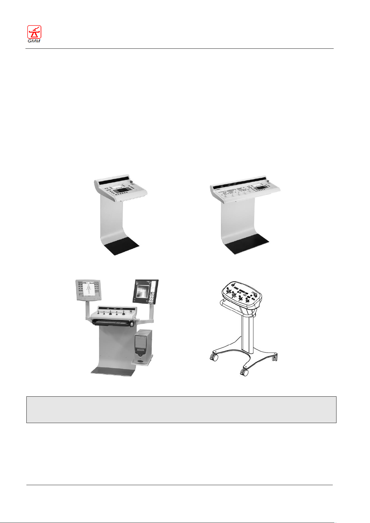
2.3.5. Control console
The control console represents the main contact point between the operator and system.
Considerable care was therefore dedicated to this important element especially concentrating on integration
of the various components commands: remote controlled table, generator and digital system (if present).
Various console configurations are available:
- Single table console
- Table and generator integrated console with push button
- Table and generator integrated console with touch screen
The control console can be supported by a floor stand or placed on desk.
The main control console layout depends on the equipment configuration (see chapter 5).
A secondary, on-trolley console with joystick is available, as an option, for the examination room (see chapter
6). This console allows the operator to control all the table movements, while remaining next to the patient.
This manual contains all the information on operating the examination table and the user interface. For
specific information regarding the single components such as the digital system, the generator and the
collimator, please refer to the respective operator’s manual.
Page 25

OPERATOR'S MANUAL OPERA T
August 2020
Page 21/135
GENERAL MEDICAL MERATE S.P.A. CODE 62235 - REVISION 13
2.4. Performance
2.4.1. Tilting
Tables can be chosen either with 90°/30° tilting system that considerably reduces the overall dimensions of
the equipment or with 90°/90° tilting to make the equipment completely symmetric. Thanks to this
characteristic the footrest can be positioned at either one table extremity or at the other, according to the
user's choice so that the most suitable condition can be defined with respect to the room entrances and the
position of the anti-X-ray booth.
Tabletop‐to‐floor distance is 86 cm both with 90°/30° and 90°/90° tilting.
The elevating 90°/90° tilting allows for setting tabletop‐to‐floor distance from 76 to 100 cm.
2.4.2. Tabletop
Tabletop can be chosen with 210 cm or 240 cm length.
The 210 cm length realizes an extremely compact table without any limitation.
The 240 cm length allows great patient explorations without repositioning.
The tabletop movements are extremely ample:
35 cm in the transversal direction
in longitudinal direction (optional):
- 160 cm (±80 cm ) with 210 cm tabletop length,
- 160 cm (±80 cm ) or 120 cm (+100/‐20 cm) with 240 cm tabletop length.
The table structure allows the operators to move easily towards the patient from any side. The patient gets
on/off easily from the table both in horizontal and in vertical.
When the table is in vertical position, if the tabletop longitudinal movement is available, it is possible to lower
the tabletop in order to ease getting on the footboard for patients with motion difficulties. For safety reasons
this operation can be commanded only from the on‐board console.
Particularly high is the patient's maximum admitted weight: 230kg without any limitations of use, up to 260kg
with limitation of use (static exams).
2.4.3. X-ray tube stand
The extended displacements of the stand make the OPERA T tables very supple.
Longitudinal displacement with image system ‐ 210 cm tabletop length:
- 124 cm, without longitudinal tabletop movement
- 108 cm with longitudinal tabletop movement.
Longitudinal displacement with image system ‐ 240 cm tabletop length:
- 154 cm, without longitudinal tabletop movement
- 138 cm with longitudinal tabletop movement.
Focus‐film distance:
- continuously variable focus‐film distance with preset positions at 115, 135, 150 and optionally 180.
High quality imaging for cardiac and chest examinations is therefore assured.
Oblique incidences:
- 40° ensure the execution of complete examinations of the spine with different incidences
in addition, the capability of layer height selection allows the operator to maintain the object to be
examined always centred on the image.
X‐ray tube assembly rotation:
- 270° with mechanical detents placed at 0°, ±18°, ±36°, ±54° ±72°, ±90° and ‐180° to allow easy execution of
examinations with cassette outside SFD, on wall bucky stand and on stretcher.
Minimum distance between X‐ray beam and table edge:
- 43 cm, makes it easy to execute effective uro‐gynaecological examinations
Page 26

OPERATOR'S MANUAL OPERA T
August 2020
Page 22/135
GENERAL MEDICAL MERATE S.P.A. CODE 62235 - REVISION 13
Due to its special structure, the table placed in vertical position ensures a great diagnostic efficiency:
- extended and easy execution of examinations on charged legs, thanks to the reduced focus‐floor distance
- examinations on stretched patients proves to be very easy since the operator can count on a large focusfloor distance and wider space for patient positioning, thanks to the ample longitudinal displacement and
long focal distance.
2.4.4. Linear tomography
OPERA T performs high level linear tomography acquisitions; digital control ensures high accuracy and
precision.
Main performances:
- possibility of execution from ‐90°(‐30°) up to 90°, with scan in both directions
- angles: 5°, 8°, 20°, 30°, 40°; (the angles 5°, 30° are not available in case of configuration with DR digital
detector)
- two speeds for each angle
- possibility to change from linear tomography to radiography on the same cassette
- selection of the layer height from 0 to 330 mm
- automatic increase of the layer height between 1 and 10 mm pre‐arranged during installation.
Page 27

OPERATOR'S MANUAL OPERA T
August 2020
Page 23/135
EXAMINATION TABLE
Tilting angles
T30cs, T30csx: 90°/30°
T90cs, T90csx, T90ce, T90cex: 90°/90°
Tilting speeds
Variable up to 6°/s
Simultaneous movements
Tilting
Longitudinal stand travel
Tabletop travel
Stand incidences
TABLETOP
Dimensions
T30cs, T90cs, T90ce: 210x80 cm
T30csx, T90csx, T90cex: 240x80 cm
Absorption
Wood stratified < 0,7 mm Al eq
Carbon fibre < 0,5 mm Al eq
Plastic laminate < 1 mm Al eq
Height from floor
T30cs, T90cs, T30csx, T90csx: 86 cm
T90ce, T90cex: variable from 76 to 100 cm
Maximum patient weight
(with patient lying on the examination table)
230 kg without limitation of use
up to 260kg with limitation of use (static exams)
Lateral movement
35 cm
Lateral movement speed
Variable up to 5 cm/s
Optional longitudinal movement
T30cs, T90cs, T90ce: ±47.5 cm or +80/-15
T30csx, T90csx, T90cex: ± 55 cm, ± 80 cm, +100/-20 cm
Longitudinal movement speed
5 cm/s
STAND
Source Image Distance (SID)
From 115 to 150 cm (optional up to 180 cm)
Longitudinal incidences
±40°
Tube rotation
270°
Longitudinal displacement with SFD
T30cs, T90cs, T90ce: 124 cm o 108 cm with
tabletop longitudinal movement
T30csx, T90csx, T90cex: 154 cm o 138 cm with
tabletop longitudinal movement
Longitudinal displacement speed
From console: variable up to 20 cm/s
From SFD: 12 cm/s
Minimum distance from table edge
43 cm
SPOT FILM DEVICE for conventional cassette
Cassette size
From 18x24 to 35x43 cm
Vertical division
1-2-3-4 for all formats in both introduction direction
5-6 for formats with size of reference larger than 24 cm
Optional crossed divisions
4-6 for formats 18x24, 24x24 e 24x30 cm in both introduction
direction
Tabletop-film distance
78 mm with concave profile
(+17 mm with flat profile)
Max. applicable Image Intensifier
40 cm
Tabletop-Intensifier distance
138 mm with concave profile
78 - 138 mm with optional I.I. elevator
(+17 mm with flat profile)
Rapid spot filming
4 images in 2 s
Fluoro‐radiography transition time
1 s
LINEAR TOMOGRAPHY DEVICE (for film/CR and R&F flat panel solutions)
Moviment
Linear with execution in the two directions
Linear tomographic area
Extended all over SFD displacement
Angles/times
5°/0.4 – 0.8 s
8°/0.4 – 0.8 s
GENERAL MEDICAL MERATE S.P.A. CODE 62235 - REVISION 13
2.5. Technical features
Page 28

OPERATOR'S MANUAL OPERA T
August 2020
Page 24/135
20°/0.6 – 1.2 s
30°/1.2 – 2.5 s
40°/1.2 – 2.5 s
Layer height selection
0 – 330 mm
COLLIMATOR
Type of command
Manual
Remote‐controlled
Automatic
Rectangular field
Standard
Iris field
Optional
Luminous centering device
Standard
Optional additional filters
1 mm Al + 0,1 mm Cu
1 mm Al + 0,2 mm Cu
2 mm Al
Inherent filtration
1 mm Al eq. (a 75 kV)
Square field at 1 m
Min 00x00 cm Max 48x48 cm
Field light pointer
>250 lx (a 100 cm, field 35x35 cm)
Radiation leakage
<40 mRh (a 100 cm, 75 kVp – 4 mA)
GRIDS
System with SFD and I.I.
SID max 150 cm
SID max 180 cm
SID max 180 cm with
double grid system*
110 lines/inch
R = 12:1 F = 120 cm
110 lines/inch
R = 12:1 F = 140 cm
110 lines/inch
R = 12:1 F = 120 cm
150 lines/inch
R = 13:1 F = 120 cm
--
110 lines/inch
R = 12:1 F = 180 cm
Grid type
Oscillating
Retractable (by push button console)
System with fixed DR flat
panel detector and I.I.
SID max 150 cm
SID max 180 cm
SID max 180 cm with
double grid system*
215 lines/inch
R = 12:1 F = 120 cm
--
215 lines/inch
R = 12:1 F = 120 cm
--
--
215 lines/inch
R = 12:1 F = 180 cm
Grid type
Fixed
Retractable (by push button console)
System with R&F flat panel
detector
SID max 150 cm
SID max 180 cm
SID max 180 cm with
double grid system*
215 lines/inch
R = 12:1 F = 120 cm
--
215 lines/inch
R = 12:1 F = 120 cm
--
--
215 lines/inch
R = 12:1 F = 180 cm
Grid type
Fixed
Retractable (by push button console)
* The dual grid system is not available for SFD version with crossed subdivisions
COMPRESSOR
Compression force
Up to 200 N
Travel
55 cm
Parking
Automatic
Optional
Interchangeable cones without automatic parking
feature
GENERAL MEDICAL MERATE S.P.A. CODE 62235 - REVISION 13
Page 29

OPERATOR'S MANUAL OPERA T
August 2020
Page 25/135
ELECTRICAL CHARACTERISTICS
Nominal line voltage
230 Vac +/- 10 %
Mains frequency
50/60 Hz
Current absorption
15 A
Thermal dissipation
500 W
Type of protection
Class I
Degree of protection
Type B
Degree of casing protection
IPX0
WEIGHTS
Equipment
660 - 790 kg - base plate 1.00 / 1,18 m2
Control console
100 kg - base plate 0,20 m
2
Cabinet
140 kg - base plate 0,21 m2
GENERAL MEDICAL MERATE S.P.A. CODE 62235 - REVISION 13
Page 30
OPERATOR'S MANUAL OPERA T
August 2020
Page 26/135
GENERAL MEDICAL MERATE S.P.A. CODE 62235 - REVISION 13
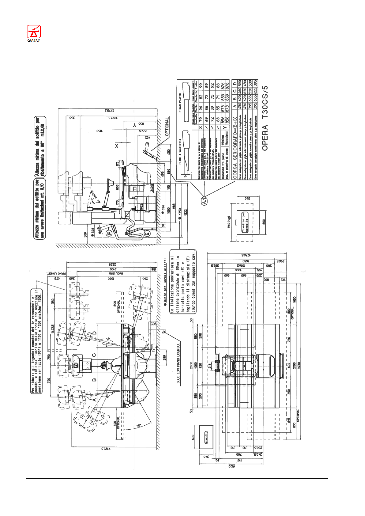
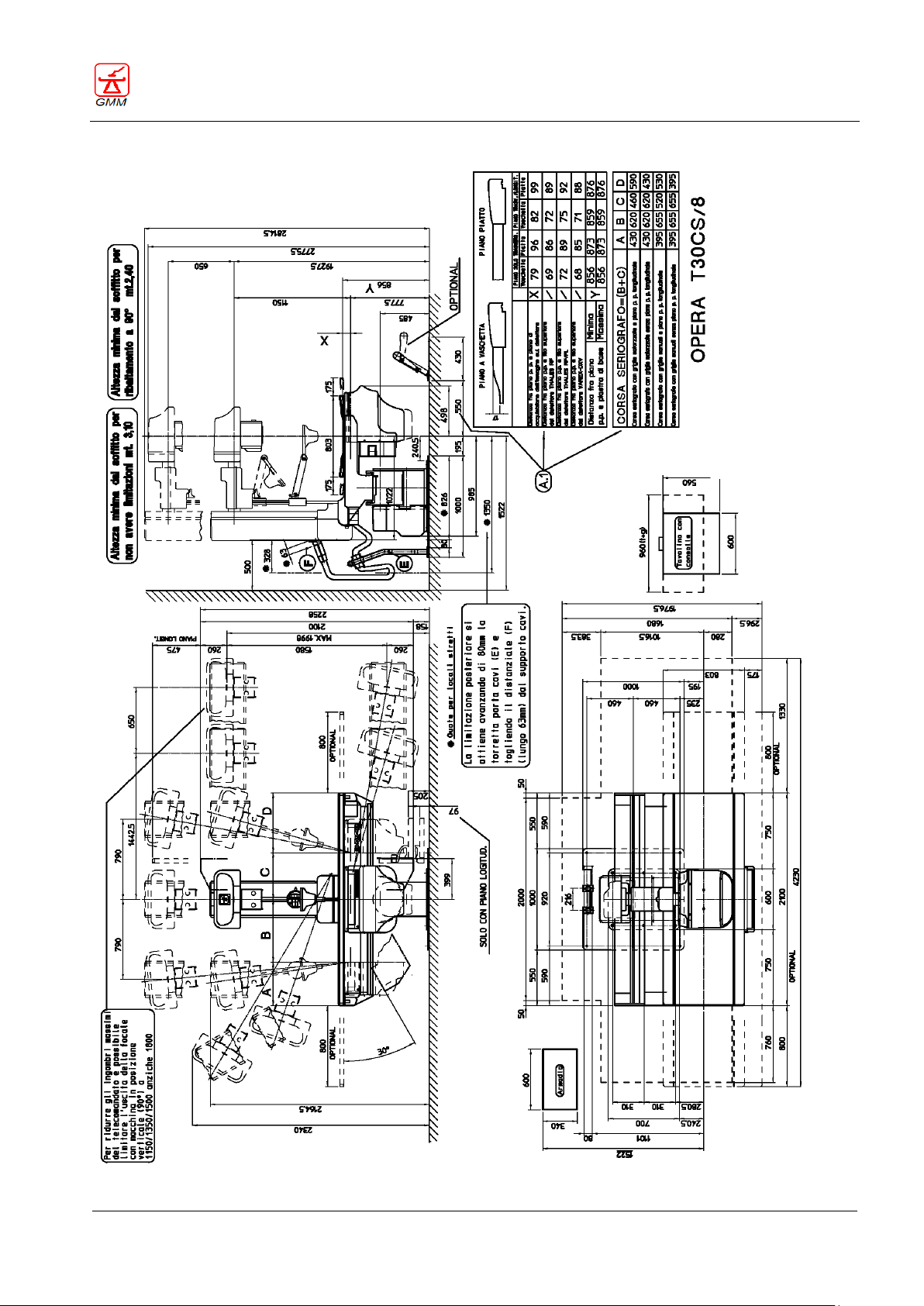
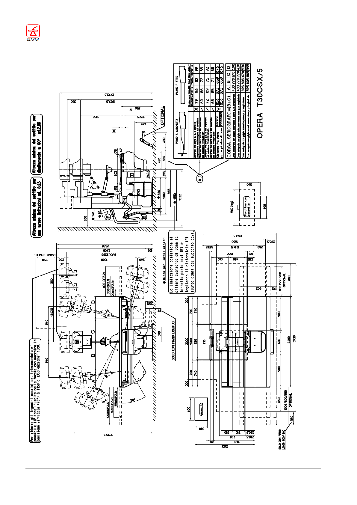
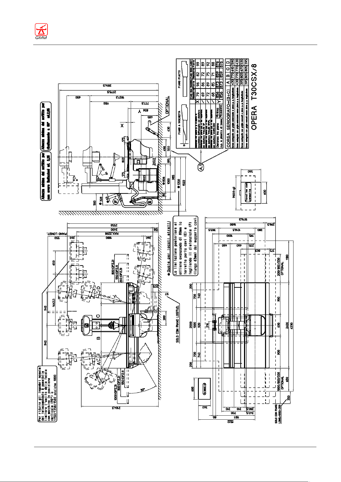
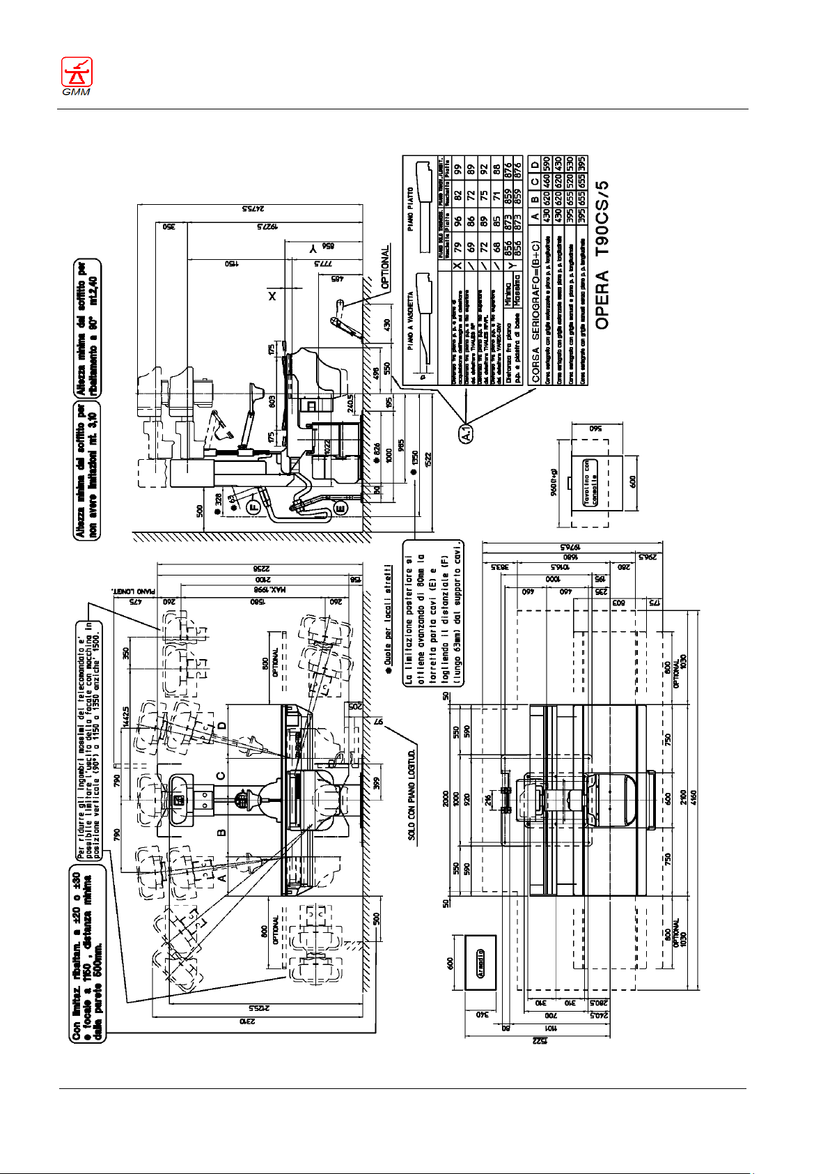
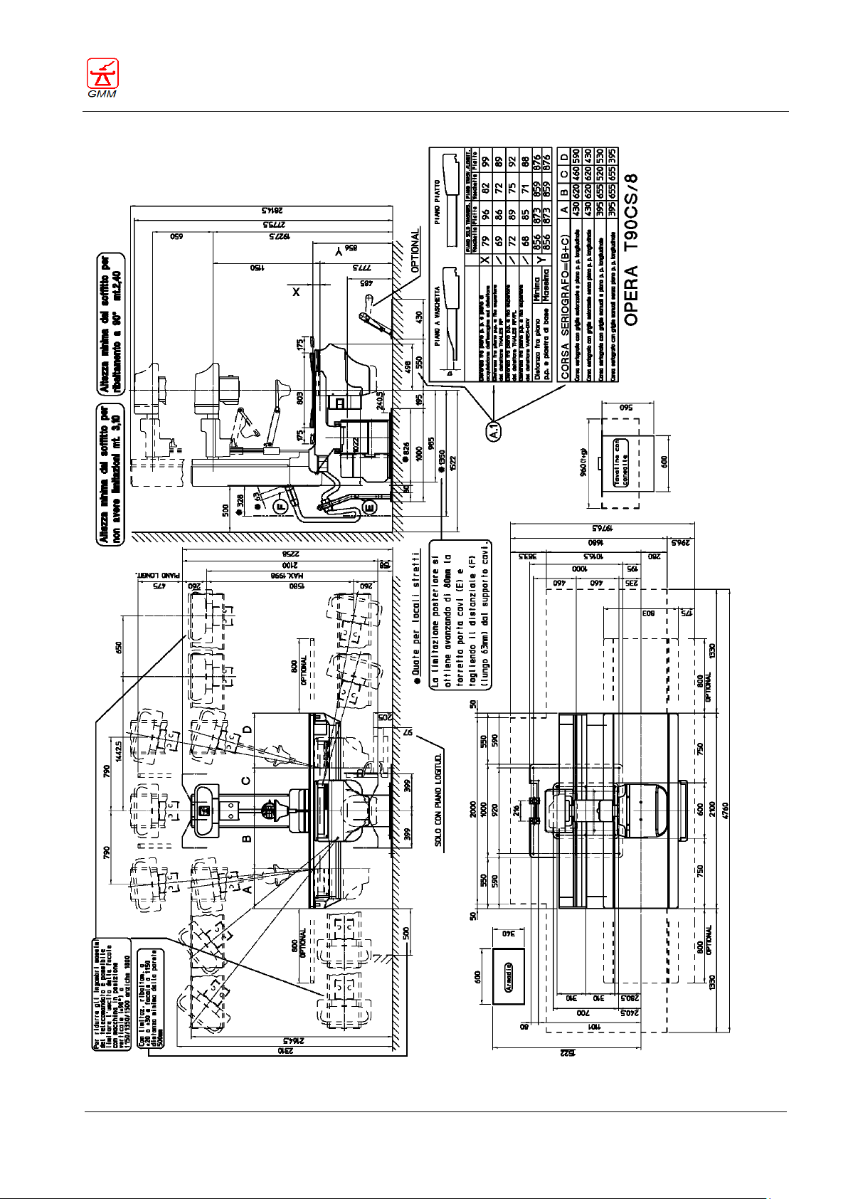
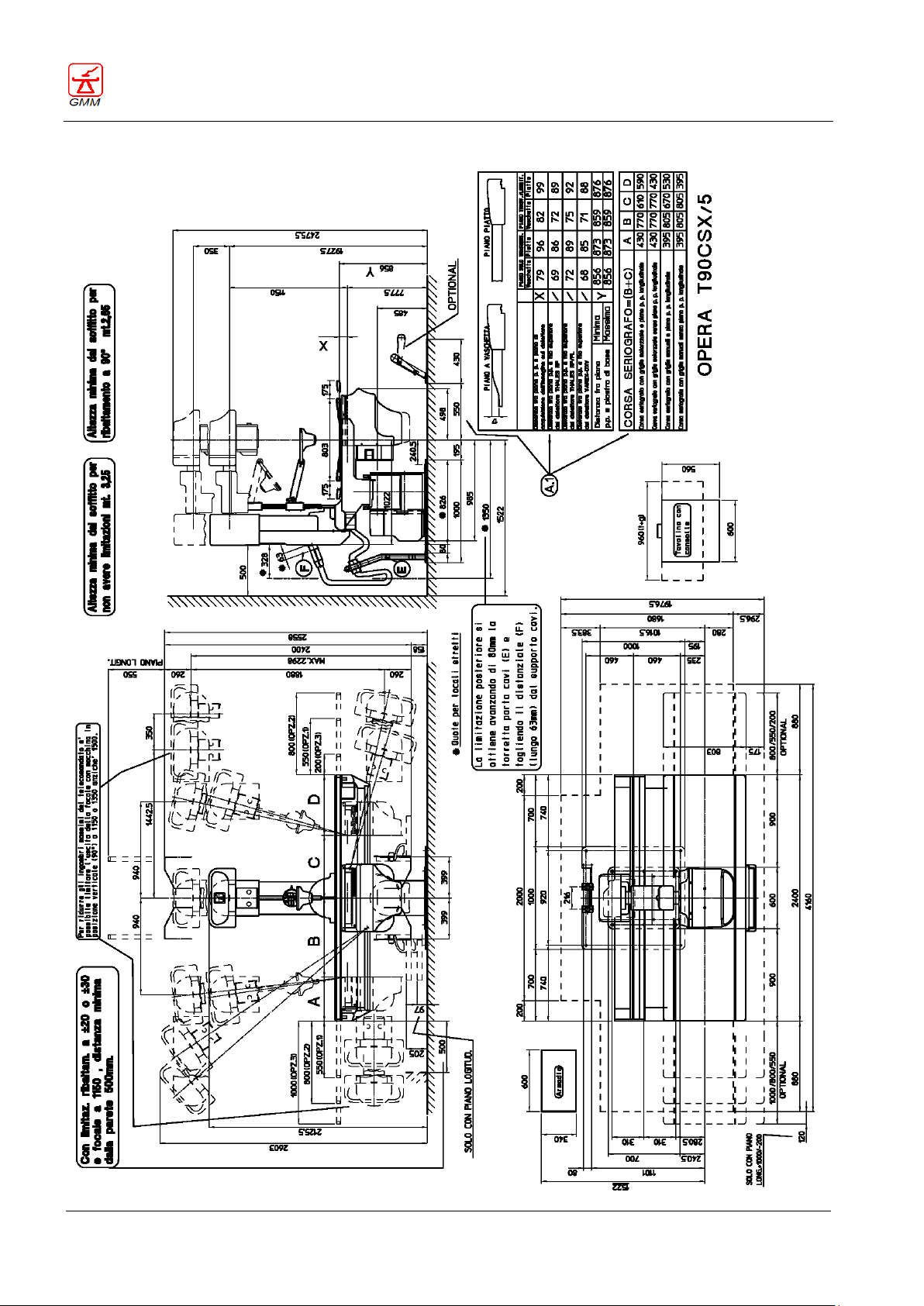
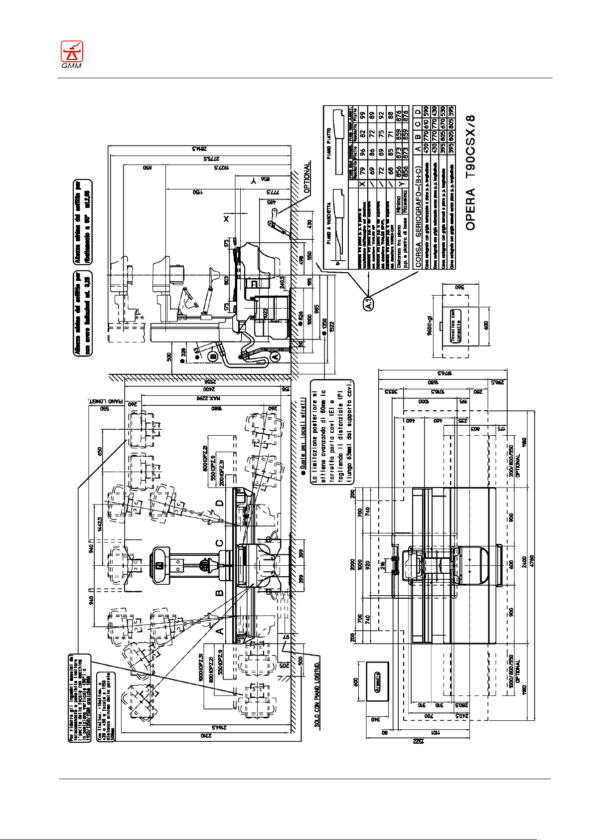
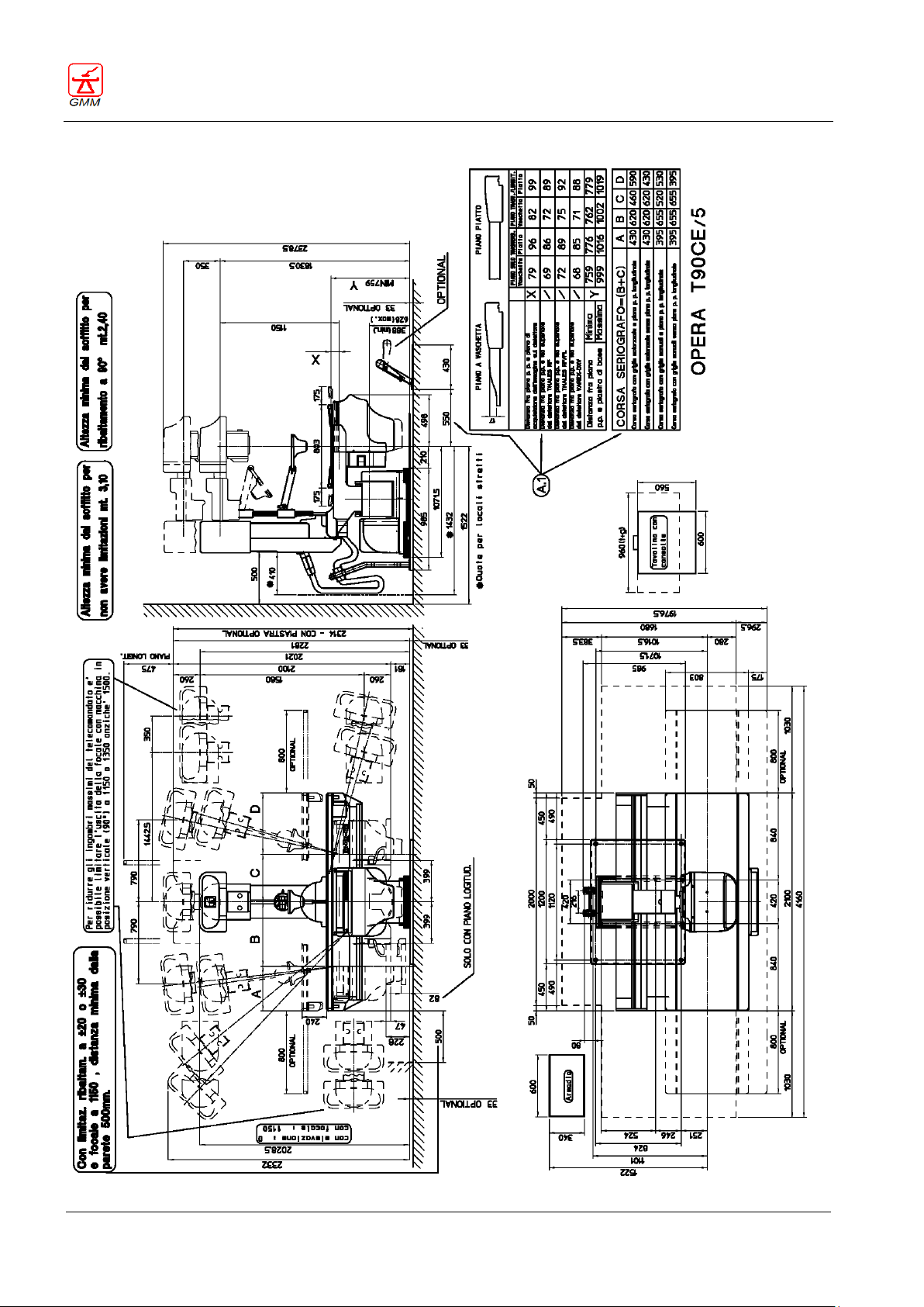
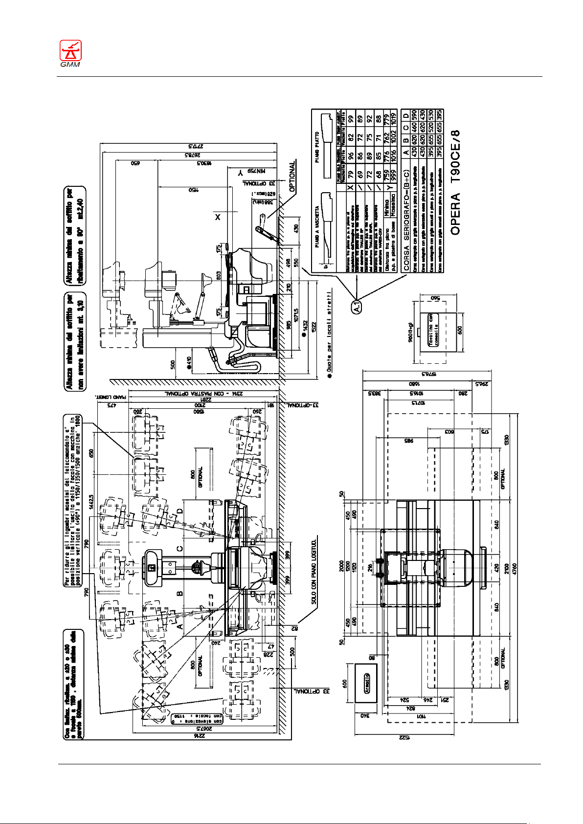
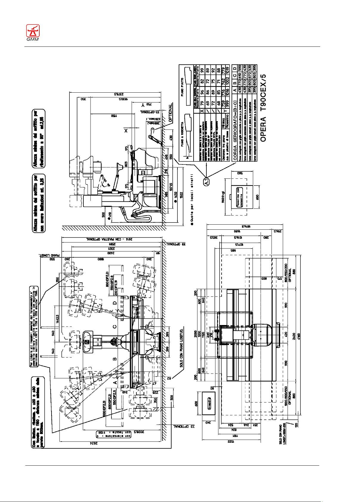
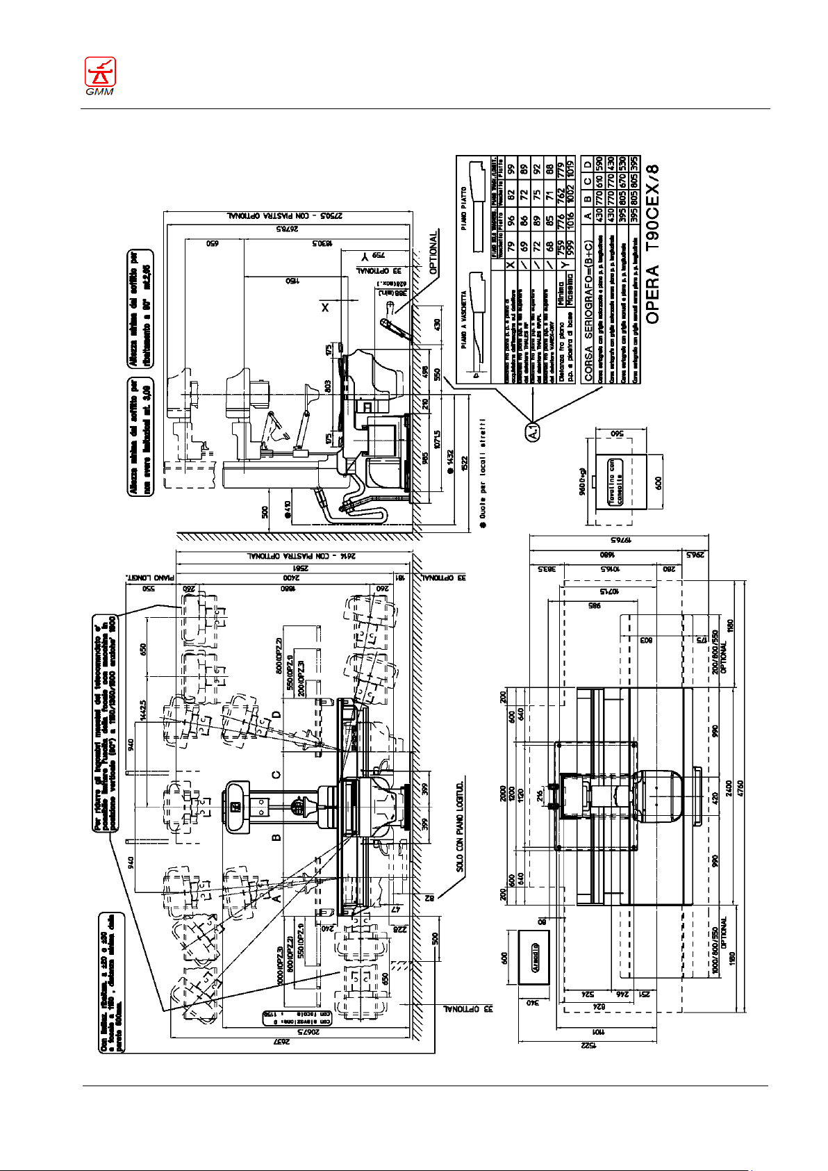
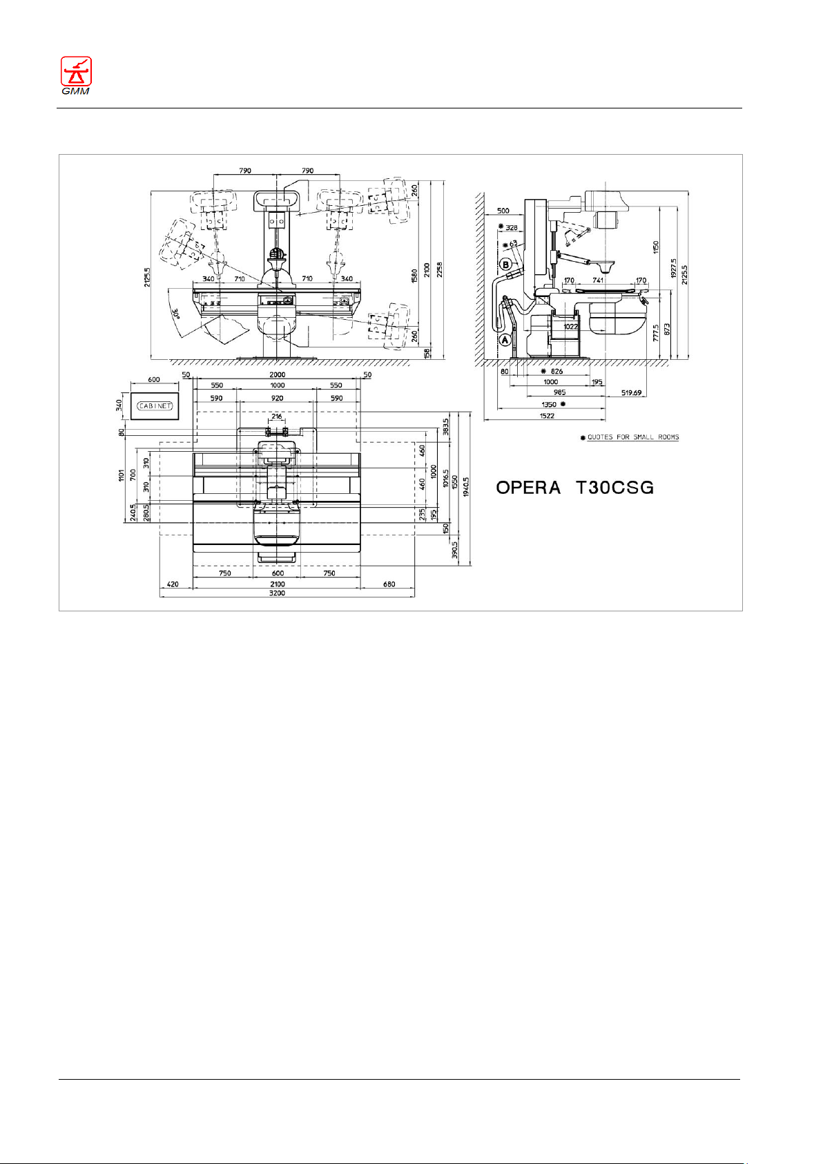
2.6. Dimension drawings
Page 31
OPERATOR'S MANUAL OPERA T
August 2020
Page 27/135
GENERAL MEDICAL MERATE S.P.A. CODE 62235 - REVISION 13
Page 32
OPERATOR'S MANUAL OPERA T
August 2020
Page 28/135
GENERAL MEDICAL MERATE S.P.A. CODE 62235 - REVISION 13
Page 33
OPERATOR'S MANUAL OPERA T
August 2020
Page 29/135
GENERAL MEDICAL MERATE S.P.A. CODE 62235 - REVISION 13
Page 34
OPERATOR'S MANUAL OPERA T
August 2020
Page 30/135
GENERAL MEDICAL MERATE S.P.A. CODE 62235 - REVISION 13
Page 35
OPERATOR'S MANUAL OPERA T
August 2020
Page 31/135
GENERAL MEDICAL MERATE S.P.A. CODE 62235 - REVISION 13
Page 36
OPERATOR'S MANUAL OPERA T
August 2020
Page 32/135
GENERAL MEDICAL MERATE S.P.A. CODE 62235 - REVISION 13
Page 37
OPERATOR'S MANUAL OPERA T
August 2020
Page 33/135
GENERAL MEDICAL MERATE S.P.A. CODE 62235 - REVISION 13
Page 38
OPERATOR'S MANUAL OPERA T
August 2020
Page 34/135
GENERAL MEDICAL MERATE S.P.A. CODE 62235 - REVISION 13
Page 39
OPERATOR'S MANUAL OPERA T
August 2020
Page 35/135
GENERAL MEDICAL MERATE S.P.A. CODE 62235 - REVISION 13
Page 40
OPERATOR'S MANUAL OPERA T
August 2020
Page 36/135
GENERAL MEDICAL MERATE S.P.A. CODE 62235 - REVISION 13
Page 41
OPERATOR'S MANUAL OPERA T
August 2020
Page 37/135
GENERAL MEDICAL MERATE S.P.A. CODE 62235 - REVISION 13
Page 42
OPERATOR'S MANUAL OPERA T
August 2020
Page 38/135
GENERAL MEDICAL MERATE S.P.A. CODE 62235 - REVISION 13
All dimensions are in mm.
Page 43
OPERATOR'S MANUAL OPERA T
August 2020
Page 39/135
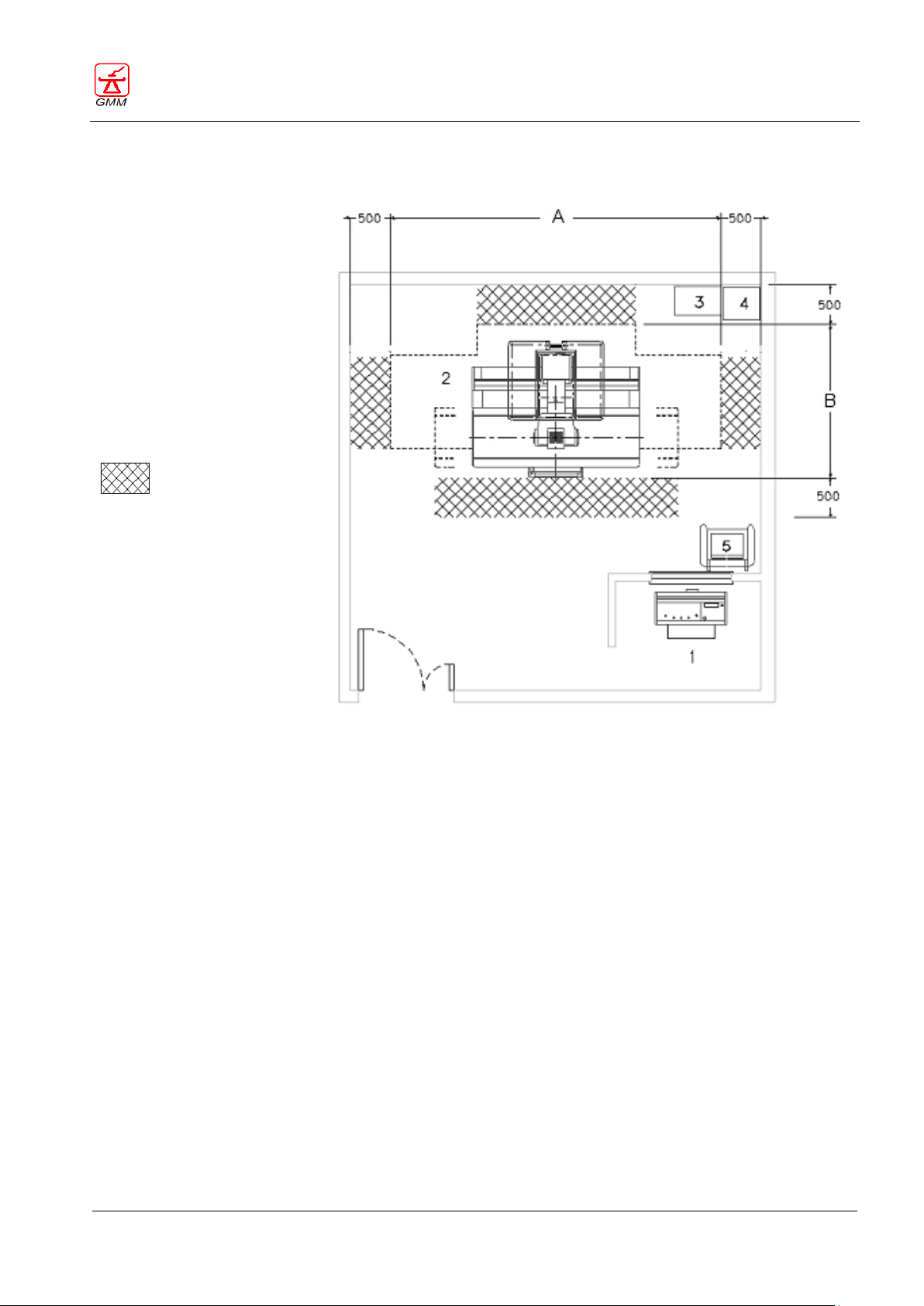
1 control console
2 table
3 digital system cabinet (if
present)
4 generator cabinet
5 monitor
A max. longitudinal dimension
B max. transversal dimension
(dimensions are in mm)
safety area
GENERAL MEDICAL MERATE S.P.A. CODE 62235 - REVISION 13
2.7. Diagnostic room: typical layout
The manufacturer proposes the layout of a typical diagnostic room, similar to the one seen in the above
picture, which gives the operator complete visual contact with moving tabletop and monitor the patient even
from the remote control station. If it is not possible to use this layout, the manufacturer and clinic engineer
will assess all possible solutions to guarantee a safe working environment, eliminating all possible risks.
If the control console (1) is installed in other positions, (for instance laterally with respect to the tabletop), the
operator and patient are both exposed to risks caused by lack of visibility when the machine is moving.
The next section provides some advice on how to guarantee the operator complete control of all movement
activities:
1. Remove the patient footrest when working in a horizontal direction with the patient on the tabletop.
2. If necessary, arrange some mirrors which ensure the patient can be monitored even in positions where
the tabletop hides the patient from view.
3. ALWAYS watch the machine and the patient when performing all movements.
The same assessments must be made for small diagnostic rooms as the settings of the dedicated software
controlling certain movements of the machine can be adjusted to suit such areas during the installation
phase.
Page 44
OPERATOR'S MANUAL OPERA T
August 2020
Page 40/135
WARNING
The main control console, remote keyboard, on-board console with joystick and secondary
console (in room) are enabled simultaneously.
DO NOT RUN SIMULTANEOUS CONTROLS FROM DIFFERENT POSITIONS.
Park the secondary console and the double R/F remote foot pedal outside the table
movement area when these devices are not in use.
The layout and presence of the push-buttons may vary according to the type of system
installed.
All possible push-buttons and their related functions can be found in the next chapters.
GENERAL MEDICAL MERATE S.P.A. CODE 62235 - REVISION 13
3. USER INTERFACE GENERAL DESCRIPTION
The user interface consists of a series of controls, both remote as well as close to the table.
OPERA T user interface includes the following components:
main control console
display on main control console
on-board control panel (remote keyboard)
secondary control console (in room) - optional
on-board control console with joystick - optional
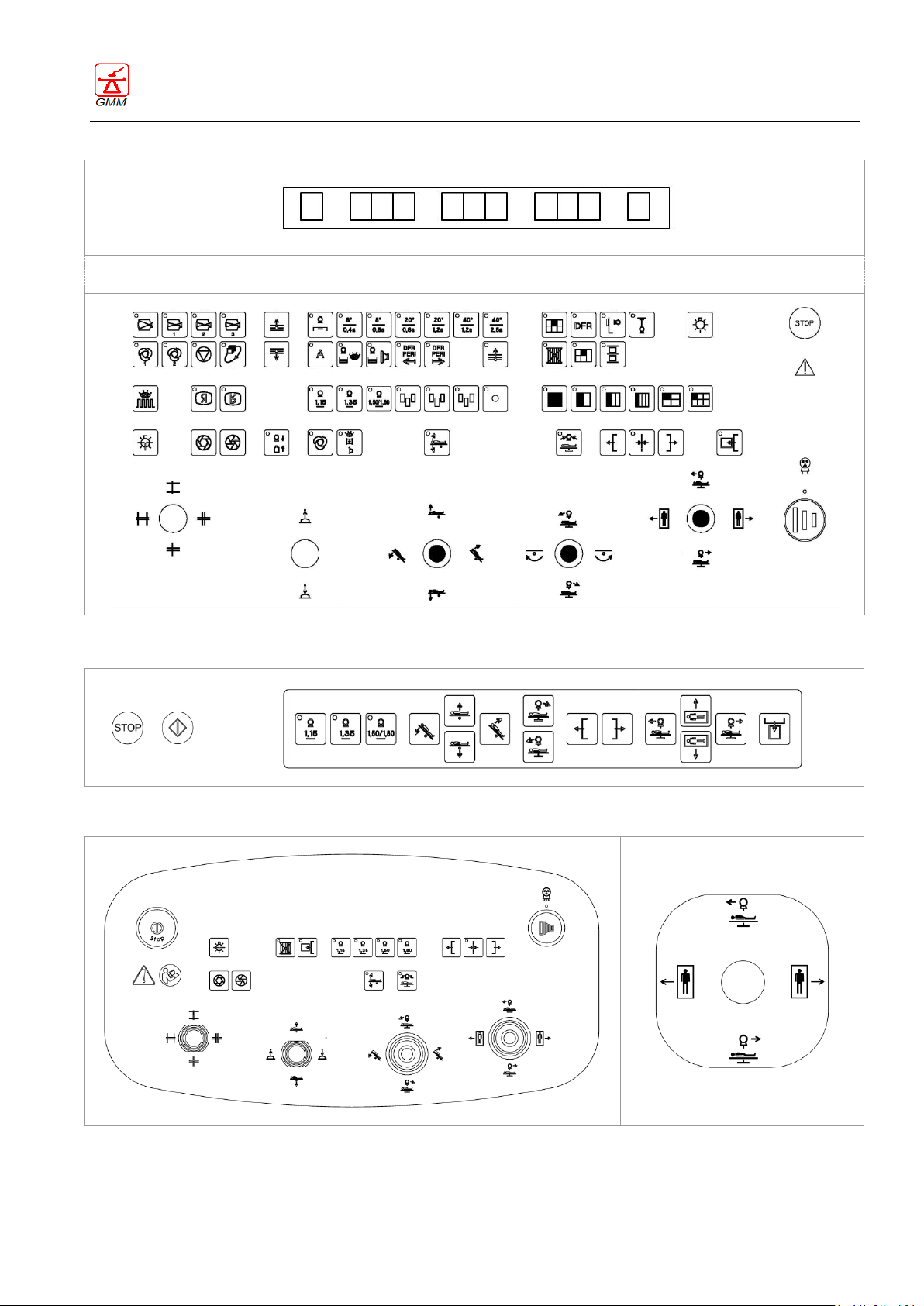
The layout of each of the above listed elements, and the chapter providing relative description, are provided
in the next page.
Page 45
OPERATOR'S MANUAL OPERA T
August 2020
Page 41/135
Display on main control console (see chapter 6)
Main control console - illustrative layout (see chapter 5)
On-board control panel (remote keyboard) - illustrative layout (see chapter 8)
Secondary control console - optional
(see chapter 7)
On-board control console with
joystick - optional (see chapter 10)
GENERAL MEDICAL MERATE S.P.A. CODE 62235 - REVISION 13
Page 46
OPERATOR'S MANUAL OPERA T
August 2020
Page 42/135
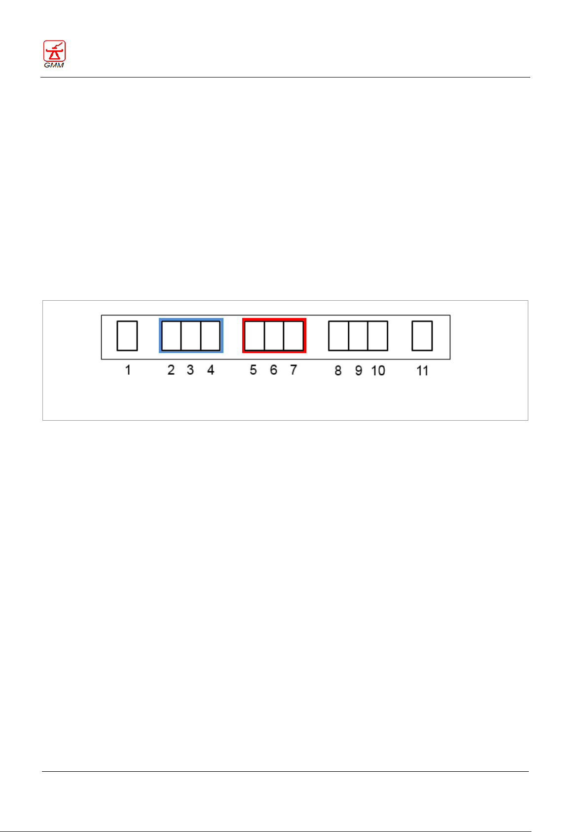
FLASHING DISPLAY: "Standby" condition indicated by flashing display (5,6,7)
ERROR DISPLAY: "Push-button malfunction during startup" condition indicated by code 97 on the display (2,3,4)
GENERAL MEDICAL MERATE S.P.A. CODE 62235 - REVISION 13
4. EQUIPMENT STARTUP PROCEDURE AND “MOVEMENT ENABLE” CONTROL
4.1. Equipment startup procedure
Upon switching on or resetting the safety/emergency status in the room or on the equipment, the following
examination table initialisation procedure is performed. During this procedure, the transmissions of the spot
film device, the I.I. and the focal distance (if installed) perform a series of automatic movements before
allowing the equipment to be used.
In systems with a 16" (40cm) adjustable table and I.I., if the table is at an elevation height of less than 60 mm,
the initialisation procedure is interrupted to prevent the I.I. from hitting the floor.
The Adjustable tabletop height – Tilting angle display (5,6,7) will start flashing on the main control console
indicating reduced functionality of the system (it is not possible to perform spot film device examinations).
To obtain full functionality of the equipment in this condition, the operator must raise the examination table
to a height of over 60 mm to permit completion of the initialisation procedure.
It is recommended to leave the equipment in position (elevation above 60 mm) before switching it off; this
will generate complete initialization of the tabletop without interruptions.
4.2. “Movement enable” control
If error code 97 is indicated on the (2,3,4) display when the equipment is switched on, one or more push
buttons, or tabletop displacement joystick on the console or remote control keyboard have malfunctioned or
have been pressed by mistake during startup.
On detecting the cause of the error, proceed as follows:
If the push-button/joystick has been pressed by mistake during startup:
Release the push-button or joystick
Turn the equipment off and then on again
If the push-button /joystick has not been pressed (malfunction), it is possible to use the equipment in
reduced operating mode, following the procedure below:
Press the (55) push-button to reset error code 97
Check all the table movements to detect which movement is inhibited; in emergency
situations use the equipment avoiding this specific movement.
Contact Technical Assistance to repair the malfunction.
Page 47
OPERATOR'S MANUAL OPERA T
August 2020
Page 43/135
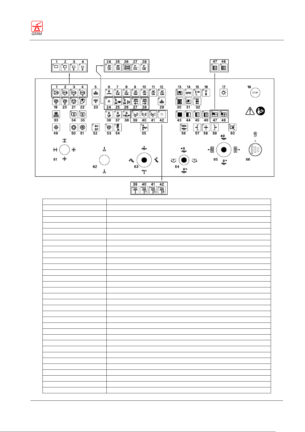
1-2-3-4
Selecting Image Intensifier or RF detector magnification
5-23
Layer height selectors
6-7-8-9-10-11-12-24-25-27-28
Tomographic functions
13-14-15-16
Operating mode display/selecting
17
Switching the X-ray room light ON or spot film device programme progress
18
Emergency STOP push-button
19-20-21
Fluoroscopy dose
22
Registration frequency or image review function
24-25-26-27-28
Angiographic exercise
26
Stitching
29
Automatic sequences during tomography
30
Parking the grid
31
Mixed programming
32
Rapid spot filming
33
Pulsed fluoroscopy mode
34-35
Monitor image inversion
36-37-38-38A
Focal distance selector
39-40-41-42
Automatic exposure or automatic filter area selector
43-44-45-46-47-48
Size division selector
49
Collimator lamp
50-51
Iris diaphragms
52
Image Intensifier elevation
53-54
Selecting the collimation (automatic/semiautomatic/bucky) mode
55
Stop in the horizontal position
56
Stand vertical position
57-58-59
Tabletop longitudinal displacement
60
Cassette holder in-out
61
Diaphragms collimation
62
Compressor
63
Tabletop elevation and tilting
64
X-ray tube stand incidences or footrest rotation
65
Longitudinal and transversal patient scanning movements
66
X-Ray exposure
GENERAL MEDICAL MERATE S.P.A. CODE 62235 - REVISION 13
5. COMMAND FUNCTIONS OF THE MAIN CONTROL CONSOLE
Page 48
OPERATOR'S MANUAL OPERA T
August 2020
Page 44/135
In order to obtain the best results, we recommend using the maximum allowed magnification
factor based on the area to be examined.
Functions available on systems equipped with I.I.
Zoom factor 4, where available, can be enabled and configured depending on the type of I.I.
being used.
1 2 3
4
Function only available with the RF detector (dynamic).
Zoom factor 4, where available, can be enabled and configured depending on the system setting.
1 2 3
4
5
23
GENERAL MEDICAL MERATE S.P.A. CODE 62235 - REVISION 13
5.1. Selecting the image intensifier or RF detector magnification factor
5.1.1. Selecting the I.I. magnification factor
Using these push-buttons (1, 2, 3 and 4), the operator can select the most appropriate I.I. (ZOOM) factor
according to the area to be examined.
5.1.2. Selecting the RF detector magnification factor
Using these push-buttons (1, 2, 3 and 4), the operator can select the most appropriate image detector factor
(ZOOM) according to the area to be examined.
5.2. Selecting the layer height
These two push-buttons (5 and 23) allow the operator to select the tomographic layer height, in addition to
the virtual fulcrum around which the X-ray tube - image receptor unit rotation is performed for oblique X-ray
or radioscopy incidences.
The layer height is visualised on the display.
Push-button (5), moves the layer height upwards.
Push-button (23), moves the layer height downwards.
The layer height ranges from 0 to 330 millimetres.
Page 49
OPERATOR'S MANUAL OPERA T
August 2020
Page 45/135
The tomographic functions, if available, are enabled and can be configured in relation to the
capacity of the system to perform tomographic functions in SFD and/or DFR.
The tomographic functions 5 (push-buttons 24, 25) and 30 (push-buttons 27, 28) are optional.
In certain systems, push-buttons (24, 25, 27, 28 ) are used to perform an angiography. In such
cases, the 5 and 30 tomographic functions cannot be enabled.
6 7 8 9 10
11
12
24
25 27
28
In some integrated systems, the selecting and disabling are performed externally by means of
the APR (Anatomical PRogramming) system. In these cases, the push-buttons (7, 8, 9, 10, 11, 12,
24, 25, 27 and 28) are selected externally. The LED will flash until the selected push-button is
pressed and held and the preparation condition is reached. Similarly, the disabling, push-button
(6) ON, is performed externally, selecting a non-tomographic APR.
The operating mode selection/display, where available, can be enabled and configured
depending on the system version.
13
14
15
16
GENERAL MEDICAL MERATE S.P.A. CODE 62235 - REVISION 13
5.3. Tomographic functions
The tomographic functions can be enabled by pressing one of these push-buttons (7, 8, 9, 10, 11, 12, 24, 25,
27 and 28). Each push-button allows the selection of the angle and scanning time. The LED will flash until the
preparation condition is reached.
Push-button (6) disables the tomographic functions (condition enabled when the equipment is switched
on).
If you press and hold one of the following push-buttons (7, 8, 9, 10, 11, 12, 24, 25, 27 and 28) the column
stand and spot film device or detectorwill automatically return to the tomographic area, they will be
centered, and the focal distance will be positioned at 115 cm (note that if the focal distance is at 8° it will
remain in the same position) and the compressor will move to its parking position.
5.4. Operating mode selector/display
These push-buttons allow the operator to select and/or display the image acquisition mode, according to the
following operating modes:
Conventional X-ray on CR or DR film (push-button 13)
Digital fluoroscopy on I.I. or digital exams (RAD/Fluoride) on RF detector (push-button 14).
Exams on bucky stand, stretcher or tabletop, with X-ray housing rotation (push-button 15)
Exams with ceiling stand (push-button 16).
It is possible to alternate the enabled operating modes at any time.
The selected operating mode is indicated by the relative LED.
In case it is necessary to perform exams signalled by the indicator (15), the LED is activated when the X-ray
group is released from its normal position, (aligned on the image receptor).
Page 50
OPERATOR'S MANUAL OPERA T
August 2020
Page 46/135
WARNING
If the tube is rotated and the “external radiography” accessory is used, the X-ray beam will
extend beyond the primary safety barrier.
The X-ray room light ON or spot film device programme progress functions, push-button (17)
can be enabled and configured depending on the system version. The two functions can only
be used alternatively.
The spot film device programme progress function can only be enabled using conventional
spot film devices.
17
18
Used cassette size division
Unused cassette size division
GENERAL MEDICAL MERATE S.P.A. CODE 62235 - REVISION 13
In case it is necessary to perform exams with the ceiling stand, the LED (16) is activated when the ceiling stand
has been released from its parking position.
In this condition all the tabletop movements that can cause collision with the stand are inhibited.
5.5. Switching the X-ray room light ON or spot film device programme progress
5.5.1. Switching the X-ray room light ON
Press this push-button (17) to switch the X-ray exam room light ON.
5.5.2. Spot film device programme progress
Pressing this push-button (17) it is possible to skip one or more divisions of the selected cassette size until you
reach the cassette division to be used for the exposure. The unused cassette size divisions can be performed
by reloading the cassette and skipping the cassette divisions previously exposed to X-rays.
Cassette inserted for the first time Same cassette used a second time.
4 4
3 3
2 2
1 1
5.6. Emergency Stop push button
A large red button (18) is positioned on the console to start and stop the examination table.
By pulling the button upwards the electrical circuits of the table are enabled, vice-versa by pushing it down
they are disabled.
Page 51
OPERATOR'S MANUAL OPERA T
August 2020
Page 47/135
There is also another stop button (red button - G1) with the same functions located on the left
side of the spot film device.
The fluoroscopy dose selectors, where available, can be enabled and configured depending on
the system version.
19
20
21
The registration frequency or image review function, where available, can be enabled and
configured depending on the system version.
When a push-button is present with no function enabled, the push-button is free (no function
paired).
22
The angiographic exercise functions, where available, can be enabled and configured
depending on the system version.
On some systems push-buttons (24, 25, 26, 27, 28) are used for the tomographic function, pushbuttons (24, 25, 27, 28) and push-button (26) for stitching. In such cases, the tomographic
exercise functions cannot be enabled.
Push-buttons (24 and 25) are not enabled.
24
25
26
27
28
GENERAL MEDICAL MERATE S.P.A. CODE 62235 - REVISION 13
The symbol placed below this push-button is to remind the operator that before he starts using the
equipment it is necessary to be informed about its functional performance, or carefully read this manual.
5.7. Fluoroscopy dose
Push-buttons (19 and 20) can be used to select the automatic dose level between the two variation curves
preset by the generator. Push-button (21) is used to enable manual fluoroscopy using the generator controls.
5.8. Registration frequency or image review function
Push-button (22) in combination with push-button (33) and an appropriate TV system, performs the following
functions:
In acquisition mode (fluoroscopic pedal pressed), push-button (22) starts/stops image sequence
memorization at the speed previously selected by push-button (33).
In review mode, this push-button (22) starts/stops sequence image display previously stored at the speed
selected by push-button (33).
For further information on how to use this function, please refer to the TV system manuals.
5.9. Angiographic exercise
Page 52
OPERATOR'S MANUAL OPERA T
August 2020
Page 48/135
Push-button (6) disables the peristepping functions (condition enabled when the equipment is
switched on).
6
Push-button (6) disables the periscanning functions (condition enabled when the equipment is
switched on).
6
GENERAL MEDICAL MERATE S.P.A. CODE 62235 - REVISION 13
For further information on how to use the Angiographic exercise functions, please refer to the digital system
manuals.
5.9.1. Peristepping functions: push-buttons (27) and (28)
The peristepping functions can be activated by pressing one of these push-buttons (27) and (28).
Push-button (27) is used to select phlebography mode and feet-head (right-left) scan direction.
Push-button (28) is used to select angiography mode and head-feet (left-right) scan direction.
The LED will flash until the preparation condition is reached.
Press and hold button 27 or button (28) to activate automatic return of the stand and SFD to the
peristepping zone, stand/spot film device centering and the positioning of the focal distance of 115 cm. In
addition, the compressor will move to its parking position.
The number of "Steps" available will be displayed on the incidences display.
It is possible to use the mobile area joystick to search for the phlebography/angiography starting position
and change the number of steps accordingly.
On pressing the X ray button:
the acquisition sequence will commence (step one)
when step one has been completed, the digital device will send the automatic forward feed command
the tabletop/generator/digital device will move into position for the next step
on reaching the next step, a new acquisition will start as far as the last possible step
If the X ray button is released (2nd click) during the image acquisition phase, but the preparation button is not
released (X ray button 1st click), the image sequence will be manually interrupted.
The system will consequently move on to the next step, and all the above described functions will be
repeated.
5.9.2. Periscanning function: push-button (26)
The periscanning function is enabled by pressing push-button (26), this same button allows head-feet (leftright) direction scanning.
The LED will flash until the preparation condition is reached.
Press and hold button 26 to activate automatic return of the stand and SFD to the periscanning zone,
stand/SFD centering, the compressor moves to its parking position, whilst the perpendicular collimator
blades will close automatically at a closed field.
It is possible to use the mobile area joystick to search for the scan position.
Press and hold the X ray button to start the scan and acquisition sequence that will continue until the
button is released.
Page 53
OPERATOR'S MANUAL OPERA T
August 2020
Page 49/135
The Stitching function, where available, can be enabled and configured depending on the system
version.
In certain systems, this push-button (26) is used for the angiographic exercise. In this case, the
stitching function cannot be enabled.
In some integrated systems, the selecting and disabling are performed externally by means of the
APR (Anatomical PRogramming) system. In these cases, the push-button (26) is selected
externally. The LED will flash until the selected push-button is pressed and held and the
preparation condition is reached. Similarly, the disabling, push-button (6) ON, is performed
externally, selecting a non Stitching APR.
Push-button (6) disables the Stitching function (condition enabled when the equipment is
switched on).
6
26
GENERAL MEDICAL MERATE S.P.A. CODE 62235 - REVISION 13
5.10. Stitching
Press this push-button (26) to enable the Stitching function. The push-button LED will flash until the
preparation condition is reached.
Hold this button to obtain automatic return of the column stand and the spot film device or detector to
the stitching zone and subsequent centering; the compressor also moves to its parking position.
Stitching can be performed in 0° or ±90° conditions and a focal distance of from 115 to 150 cm; check you
have achieved these conditions before selecting the stitching function.
Inside the stitching area it is possible to perform the patient scan movement using the joystick (65) to
move to the required stitching position.
The number of imaged and the stitching direction are established according to the examination selected
on the relative digital system.
Press this push-button (66) to start the stitching sequence for x-ray exposures. The button must be held
down until the end of the sequence, its release will interrupt the stitching sequence and the digital system
will process the images acquired up until then.
Press this push-button (66) for x-ray exposures:
The X-ray tube unit reaches the start sequence position (step one)
The digital device receives authorisation for acquisition of the first image
When the first acquisition has been completed, the digital device will send the automatic
forward feed command
The tabletop/generator/digital device will move into position for the next step
On reaching the next step, a new acquisition will start as far as the last possible step
On completing the sequence, the system will display the stitching of the acquired images on
the digital monitor.
To repeat the sequence, it is necessary to run the stitching sequence again starting by re-selecting the
examination.
For further information on how to use the Stitching function, please refer to the digital system manuals.
Page 54
OPERATOR'S MANUAL OPERA T
August 2020
Page 50/135
The Automatic sequence during tomography, if available, is linked to the tomographic functions.
29
The Grid parking function, where available, can be enabled and configured depending on the
system version.
In some integrated systems, the selecting is performed externally by means of the APR
(Anatomical PRogramming) system. In these cases, the push-button (30) is selected externally and
the push-button, even if present, is never used. In other systems, it is possible to change the
position of the grid after it has been selected from the APR system.
When the table has two grids, on pressing this push-button (30), the relative grid will be moved
automatically in relation to the focal distance.
30
The Mixed programming function, where available, is paired to the examination tables equipped
with a conventional spot film device and it depends on the system version.
Mixed programming is not enabled with a number of over 4 band divisions.
31
GENERAL MEDICAL MERATE S.P.A. CODE 62235 - REVISION 13
5.11. Automatic sequences during tomography
Push-button (29) allows you to automatically increase the height of the tomographic layer set during the
installation procedure, from 1 to 10 mm.
5.12. Grid parking
Pressing this push-button (30) it is possible to park the grid outside the X-ray beam field:
LED ON and flashinggrid parked, outside the X-ray beam field
LED OFFgrid inside the X-ray beam field
5.13. Mixed programming
Press this push-button (31) to enable the mixed programming function and the division execution sequence
available is selected automatically.
It is possible to change the type of division within a program.
According to the cassette size and the type of SFD (with or without crossed-division) some push-buttons (43,
44, 45, 46, 47 and 48) are disabled, while the remaining ones can be selected in order to select the division
execution sequence. The selected sequence is indicated by the fixed LED for the program that is first executed
and will flash for the program executed later on.
Page 55
OPERATOR'S MANUAL OPERA T
August 2020
Page 51/135
The Rapid spot filming function, where available, is paired to the examination tables equipped
with a conventional spot film device and it depends on the system version.
32
The Pulsed fluoroscopy function, where available, can be enabled and configured depending on
the system version.
The function is disabled if the DFR mode button (14) is present.
33
The Monitor image inversion function, where available, can be enabled and configured
depending on the system version.
34
35
GENERAL MEDICAL MERATE S.P.A. CODE 62235 - REVISION 13
5.14. Rapid spot filming
If you simultaneously press this push-button (32) and the X-ray exposure push-button a series of exposures
will automatically be executed according to the chosen size division.
This function will be disabled at the end of the exposure of the last section of the film or as soon as the
exposure push-button is released.
5.15. Pulsed fluoroscopy
This push-button (33) allows you to set the image review or memorization frequency.
The value associated to the image review or memorization frequency is displayed on the display screen.
For further information on how to use the Pulsed fluoroscopy function, please refer to the TV system
manuals.
5.16. Monitor image inversion
These push-buttons (34 and 35)can be used to select image inversion:
Right-left (push-button 34)
Up-down (push-button 35)
Page 56
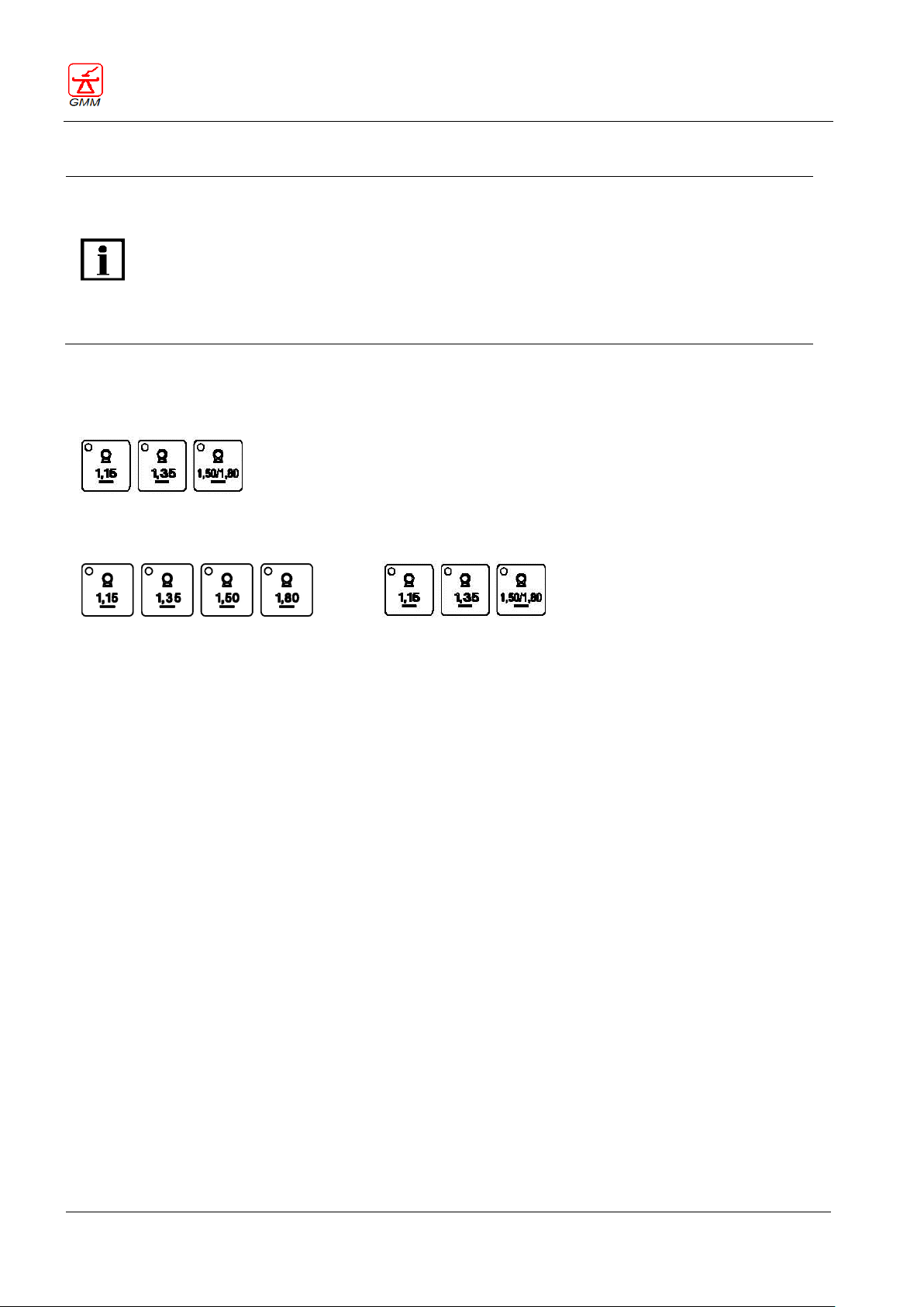
OPERATOR'S MANUAL OPERA T
August 2020
Page 52/135
The Focal distance selector function, where available, can be enabled and configured
depending on the table type.
Some table configurations foresee a maximum focal distance of 150, other configurations
foresee a maximum focal distance of 180.
The step-by-step or continuous operating mode for mobile focal distance can be configured
when the table is installed.
Moreover, in some configurations, the maximum fluoroscopy X-ray dose value is compensated
in relation to the focal distance.
Systems with max FFD = 150
3 push-button system
36
37
38
Systems with max FFD = 180 optional
4 push-button system
3 push-button system
36
37
38
38A
36
37
38
GENERAL MEDICAL MERATE S.P.A. CODE 62235 - REVISION 13
5.17. Focal distance selector
The function of the Focal distance Selector push-buttons, in particular push-button (38), varies according to
the configuration, as illustrated below:
It is possible to select from three (or four) different focal distances by pressing the relative push-button (36,
37and 38 or38A), using one of the two procedures below:
Focal distance step by step movement selector:
If you release the push-buttons before the correct distance is reached, the three (or four) LEDs will flash
stopping all possible movement. It is necessary to move the focal device to one of the three (115, 135, 150
cm) or four (115, 135, 150, 180 cm) different positions in order to commence work. The push-button LED will
remain fixed when the position has been reached.
On 3 push-button systems with maximum focal distance of 180 (optional):
To set the focal distance at 180, proceed as follows:
Press the push-button (38) and release it when the position has been reached (the focal device will
position itself at 150), the push-button LED will remain fixed when the position has been reached.
Press the push-button (38) again positioning the focal device at 180, the push-button LED will remain
fixed again when the second position has been reached.
To set focal distances lower than 180, starting from FFD=180, proceed as follows:
Press push-button (36) or (37) and release it when the position has been reached (the focal device will
position itself at 150), the push-button (38) LED will remain fixed when the position has been reached.
Press push-button (36) or (37) according to the required focal distance
Focal distance continuous movement selector:
If the push-buttons are released in intermediate position (before the selected distance is reached, the
distance will be the position in which the focal device is when the push-button is released. The related LED
will only come ON when the selected focal distance has been reached, otherwise all the LEDs on the focal
distance selector push-buttons will remain OFF; it is however still possible to use the system.
The focal distance, measurable thanks to the graduated scale fitted on the compressor column, will be the
distance in which the focal device is when the push-button is released.
Page 57
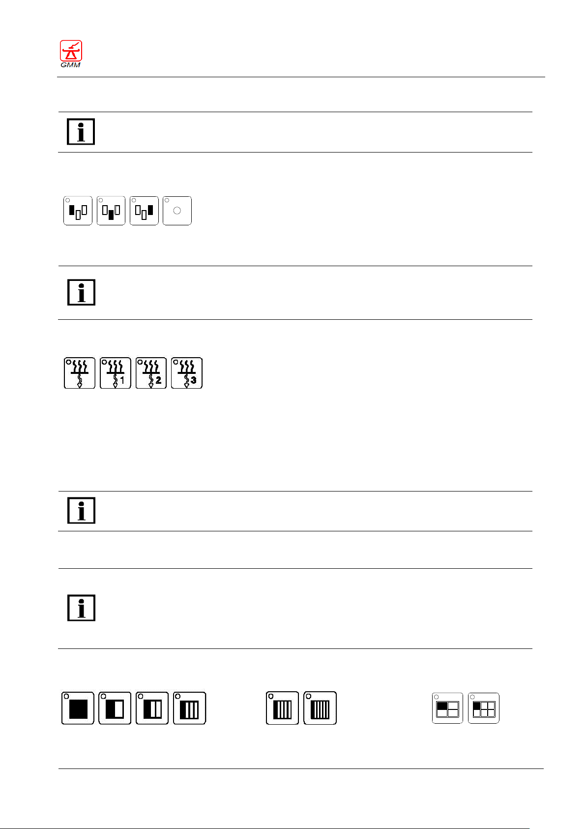
OPERATOR'S MANUAL OPERA T
August 2020
Page 53/135
The Automatic exposure or automatic filter area selectors, where available, can be enabled
and configured depending on the system version. The two functions can only be used
alternatively.
39
40
41
42
These push-buttons are only enabled in versions with a single console separated from the
generator.
When integrated consoles are used, selection takes place in the section of the console dedicated
to the generator.
39
40
41
42
These push-buttons are only enabled if the collimator with automatic filters is fitted and if the
filters are controlled from the table console. When the filters are controlled externally, (e.g. APR
digital system) the console selectors are not enabled.
The Size division selector, where available, is paired to the examination tables equipped with a
conventional spot film device, and can be enabled and configured depending on the system
version.
Some table configurations foresee the transversal division of the film size into five or six bands.
Other configurations, however, foresee crossed-divisions, therefore the push-buttons (47, 48)
will vary according to the type of system installed.
All the conventional SFDs
Conventional SFDs
with 5 and 6 band divisions
Conventional SFDs
with crossed divisions
43
44
45
46 47
48
47
48
GENERAL MEDICAL MERATE S.P.A. CODE 62235 - REVISION 13
5.18. Selecting automatic exposure or automatic filter area
1.1.1. Exposure area selector
Press the push-buttons (39, 40, 41 and 42) to enable the selected sensitive areas. Enabling is confirmed when
the LED is ON.
5.18.1. Filter selector
Press the push-buttons (39, 40, 41 and 42) to select the filter inserted in the collimator. Enabling is confirmed
when the LED is ON.
The push-buttons are paired in the following order:
Push-button (39) = no filter inserted
Push-button (40) = 1Al+0,1cu filter
Push-button (41) = 1Al+0,2cu filter
Push-button (42) = 2Al filter
5.19. Size division selector
These push-buttons (43, 44, 45, 46, 47 and 48) allow the operator to program the transversal or crossed
division of the film.
Page 58
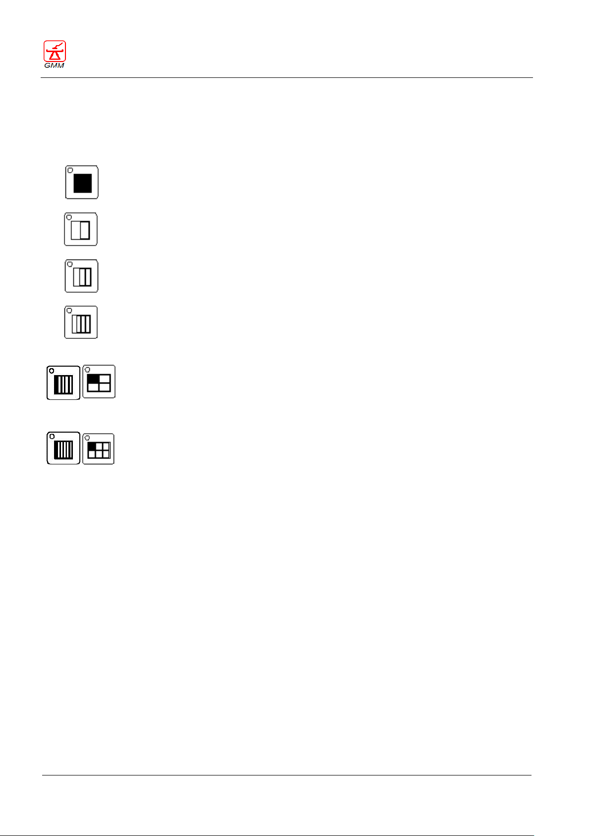
OPERATOR'S MANUAL OPERA T
August 2020
Page 54/135
43
This push-button (43) foresees the use of the film on the entire size (panoramic).
It is enabled at startup.
44
This push-button (44) allows the transversal division of the film size into two.
45
This push-button (45) allows the transversal division of the film size into three.
46
This push-button (46) allows the transversal division of the film size into four.
A B
This push-button (47) allows the transversal division of the film into five (A) or the crossed
division of the film size into four (B)
Push-button (A) is optional: installed on 5 and 6 division band spot film device systems
only.
Push-button (B) is optional: installed on crossed spot film device systems only.
47
A B
This push-button (48) allows the transversal division of the film into six (A) or the crossed
division of the film size into six (B)
Push-button (A) is optional: installed on 5 and 6 division band spot film device systems
only.
Push-button (B) is optional: installed on crossed spot film device systems only.
48
GENERAL MEDICAL MERATE S.P.A. CODE 62235 - REVISION 13
The spot film device with 2,3,4 bands or stripes allow the division of any size in the transversal direction;
The division in 5, 6 bands or stripes is only possible for sizes over 24cm or 10 inches.
The crossed spot film device in addition to the division of any size in a transversal direction, also allows
the crossed subdivision in 4 and 6 for the 18x24, 24x24, 24x30 sizes.
The LED placed on each push-button indicates the division currently selected.
The number of available exposures is always displayed according to the selected program. In addition, when
the cassette holder is in the parked position in the spot film device, it is possible to read the dimension of the
cassette inserted in the spot film device by pressing the selected cassette division button.
The selected film size division automatically determines the automatic collimation of the X-ray beam, with the
command: "Radiography preparation".
At each "Radiography" command, the division program advances one step while the number of available
exposures shown on the display decreases. After exposing the final section of the film, the cassette is
automatically sent to its parking position. The display will indicate that the division program is over (0
radiographs available) and it is not possible to perform any further radiographic exposures.
It is always possible to insert a radioscopy between one radiographic exposure and another by pressing the
radioscopic foot pedal. The following radiographic exposure will be executed by turning back to the point
where the division program was last interrupted.
When the radiographic exposure series is over, you can only perform other exposures after replacing the
radiographic cassette. When you replace the radiographic cassette, the division program last selected will
remain active.
Page 59
OPERATOR'S MANUAL OPERA T
August 2020
Page 55/135
49
The Iris diaphragms command, where available, can be enabled and configured and paired to
tables equipped with collimator with this option.
50
51
The I.I. Elevation command, where available, can be enabled and configured and paired to
examination tables with this option.
52
GENERAL MEDICAL MERATE S.P.A. CODE 62235 - REVISION 13
5.20. Collimator lamp
This push-button (49) is used to switch on or off the lamp of the luminous centring device in order to carry out
a visual check of the collimation. The lamp will automatically switch off after 30 seconds.
5.21. Iris diaphragms
These push-buttons (50 and 51) are provided to control a iris diaphragm, if available:
The left push-button (50) causes the diaphragm to open
The right push-button (51) causes the diaphragm to close
5.22. Image intensifier elevation
This push-button (52), can be used to select whether to perform fluoroscopy exams with the I.I. placed at the
minimum distance from the tabletop (normal condition) or with the I.I. left at the same distance that it
assumes when spot film device cassette-holder is in the field (condition indicated with LED on).
The normal condition is the best possible condition for geometrical magnification and resolution.
In other conditions, the fluoroscopy-radiography transition time is minimal.
Page 60
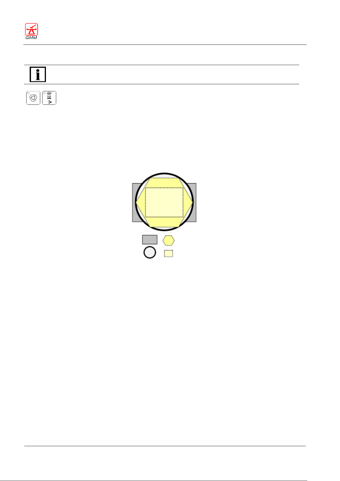
OPERATOR'S MANUAL OPERA T
August 2020
Page 56/135
The Collimation mode selectors, where available, depend on the system version.
53
54
Equivalent cassette area
Iris collimation area
Equivalent I.I. area
Orthogonal collimation area
GENERAL MEDICAL MERATE S.P.A. CODE 62235 - REVISION 13
5.23. Collimation mode selector
These push-buttons are used to select the collimation mode:
This push-button (53) selects collimation in automatic or semi-automatic mode
This push-button (54) selects collimation in Bucky mode
When neither of the two push-buttons are selected (the LED on push-button (53) is flashing), the system is set
to semi-automatic mode.
In all operating modes, it is always possible to execute collimation in reduction mode using the joystick (61) or
directly on the collimator using its knobs.
Page 61
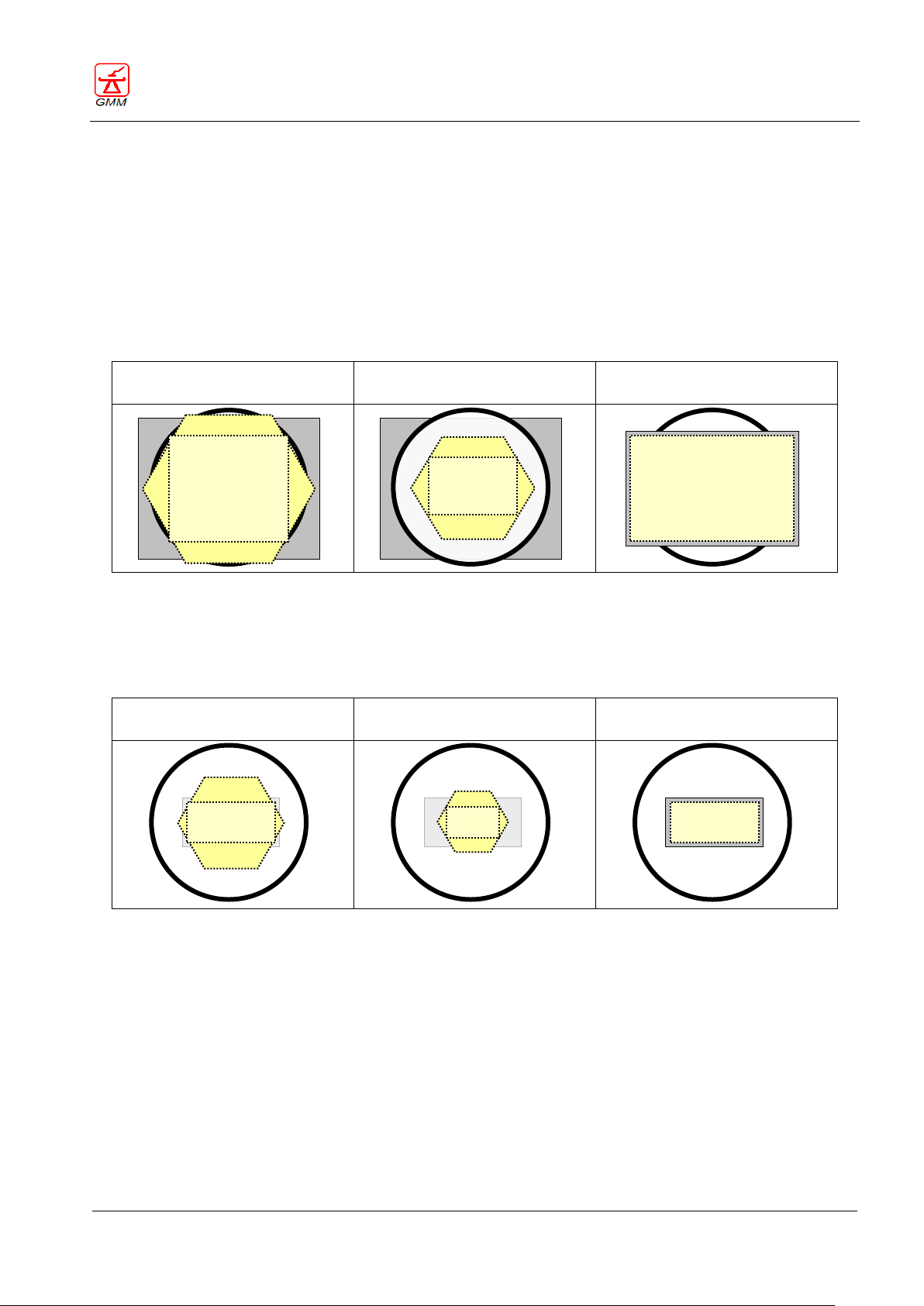
OPERATOR'S MANUAL OPERA T
August 2020
Page 57/135
Fluoroscopy
Fluoroscopy with
collimation in reduction
Radiography
(automatic collimation)
Fluoroscopy
Fluoroscopy with
collimation in reduction
Radiography
(automatic collimation)
GENERAL MEDICAL MERATE S.P.A. CODE 62235 - REVISION 13
5.23.1. Automatic collimation (Push-button 53 enabled – LED ON)
FLUOROSCOPY = I.I. OR DETECTOR FIELD SIZE)
Cassette (film) size larger than the I.I. or detector field: the X-ray field will be as large as the I.I. or detector
field selected.
Cassette (film) size smaller than the I.I. or detector field: the X-ray field will be as small as the cassette (film)
size.
During the fluoroscopy phase it is possible to open the collimator shutters as far as the I.I. or detector field
size, using the joystick (61); as soon as the joystick is released the cassette size division will return to its
previous setting.
RADIOGRAPHY = (COLLIMATION ON CASSETTE SIZE):
The X-ray field is always as large as the cassette size.
Cassette size smaller than the I.I. or detector field: the X-ray field will be as small as the cassette size.
Cassette size larger than the I.I. or detector field size: the X-ray field will be as large as the cassette size.
Page 62
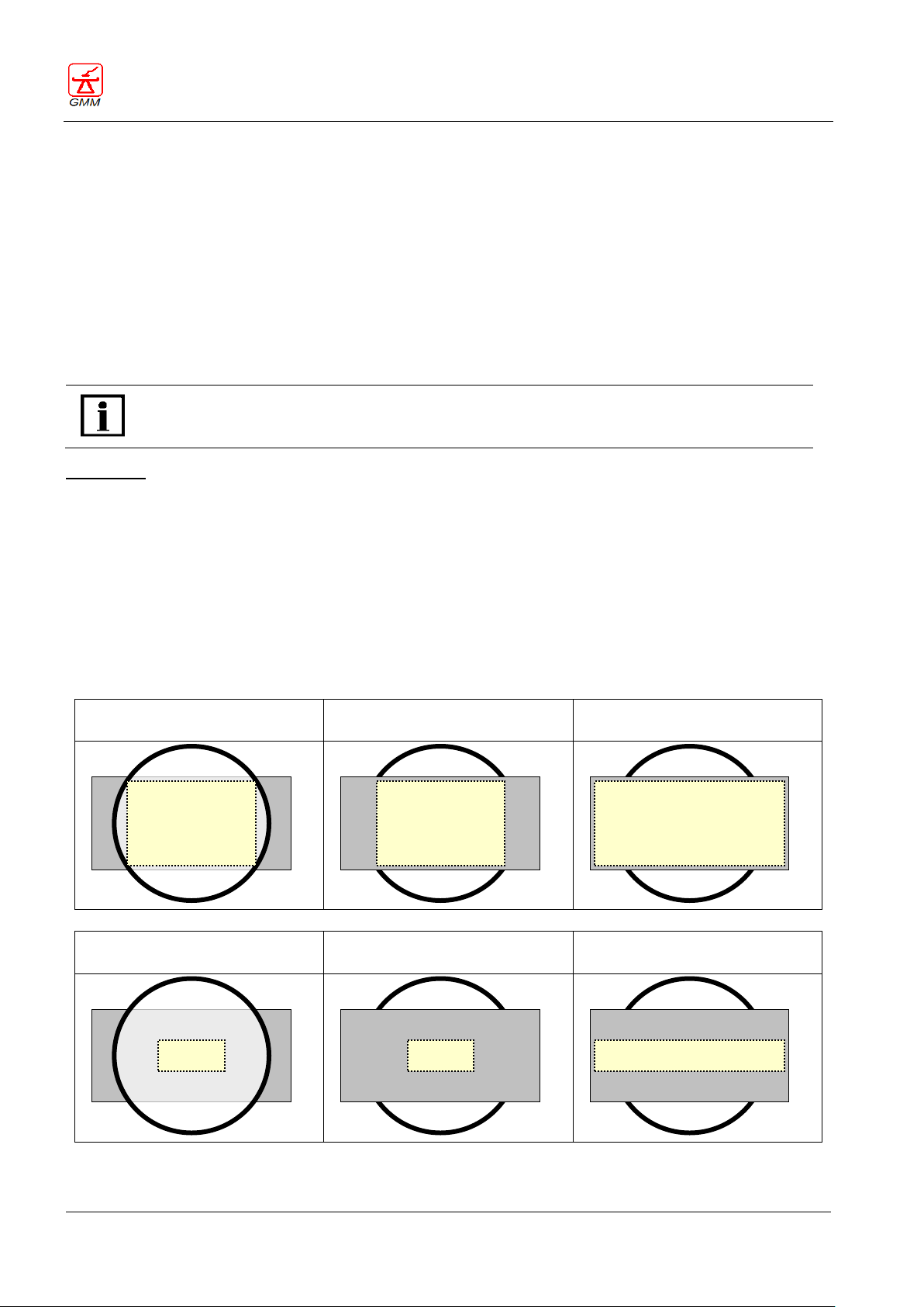
OPERATOR'S MANUAL OPERA T
August 2020
Page 58/135
The semi-automatic collimation in Radiography depends on the value set during the
installation phase. The paragraphs below describe the four different settings that provide four
different X-ray field opening modes.
Fluoroscopy (001)
Radiography (001)
Radiography with perpendicular
joystick movement (001)
Fluoroscopy with collimation in
reduction (001)
Radiography with collimation in
reduction (001)
Radiography with perpendicular
joystick movement (001)
GENERAL MEDICAL MERATE S.P.A. CODE 62235 - REVISION 13
5.23.2. Semi-automatic collimation (Push-button 53 enabled – LED flashing)
FLUOROSCOPY = COLLIMATION ON I.I. SIZE:
Cassette size smaller than the I.I. : the X-ray field will be as large as the cassette size.
Cassette size larger than the I.I. : the X-ray field will be as large as the I.I
FLUOROSCOPY = COLLIMATION ON RF DETECTOR SIZE:
Cassette size smaller than the detector size: the X-ray field will be preset to match the film size. During the
fluoroscopy phase it is possible to use the joystick (61) to open the collimator shutters until they match the
selected detector size.
Cassette size larger than the detector size: the X-ray field will be as large as the detector size.
RADIOGRAPHY:
Setting 001
COLLIMATION IN FLUOROSCOPIC = RADIOGRAPHIC MODE (the perpendicular diaphragm and the iris will only
open at film size in radiographic mode if the joystick is moved during the preparation phase).
The X ray field will always be as large as the cassette/I.I. size. - never larger than the I.I.
In Radiographic mode:
If the joystick (61) is not moved perpendicularly during the radiography preparation phase:
The parallel sides, perpendicular and iris, if present, remain stationary in the previously selected
position.
If the joystick (61) is moved perpendicularly during the radiography preparation phase:
The parallel side remains stationary in the previous position.
The perpendicular side and iris open on the film size (maximum aperture)
Page 63
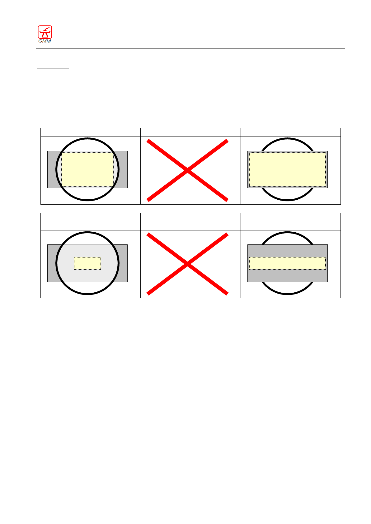
OPERATOR'S MANUAL OPERA T
August 2020
Page 59/135
Fluoroscopy (002)
Radiography (002)
Fluoroscopy with collimation in
reduction (002)
Radiography (002)
GENERAL MEDICAL MERATE S.P.A. CODE 62235 - REVISION 13
Setting 002
COLLIMATION APERTURE PERPENDICULAR SIDE AT THE FILM SIZE SELECTED IN RADIOGRAPHIC MODE (the
perpendicular diaphragm and iris always open in radiographic mode at the film size).
In Radiographic mode:
- The parallel side remains stationary in the previously selected position.
- The perpendicular side and iris, if present, always open on the film size (maximum allowed aperture)
even if previously collimated.
Page 64
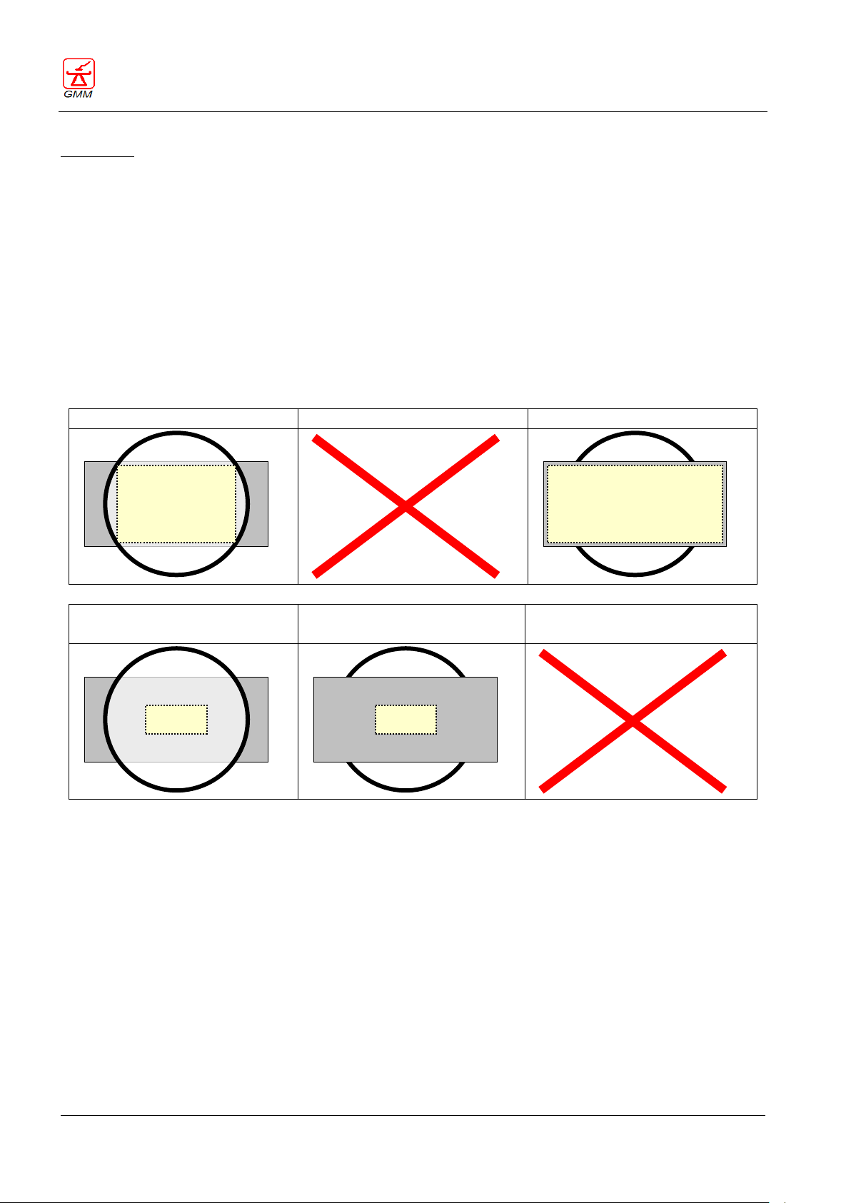
OPERATOR'S MANUAL OPERA T
August 2020
Page 60/135
Fluoroscopy (003)
Radiography (003)
Fluoroscopy with collimation in
reduction (003)
Radiography (003)
GENERAL MEDICAL MERATE S.P.A. CODE 62235 - REVISION 13
Setting 003
COLLIMATION APERTURE PERPENDICULAR SIDE AT THE FILM SIZE SELECTED IN RADIOGRAPHIC MODE IF
NOT COLLIMATED (the perpendicular diaphragm and iris open in radiographic mode at the film size if they
were not collimated in fluoroscopic mode).
In Radiographic mode:
If the size of the perpendicular side is not reduced using the joystick (61) before the radiographic phase:
The parallel side remains stationary in the previously selected position.
The perpendicular side remains on the film size (maximum allowed aperture)
The iris, if present, opens on the film size (maximum allowed aperture) even if previously collimated.
If the size of the perpendicular side is reduced using the joystick (61) before the radiographic phase:
The parallel side remains stationary in the previously selected position.
The perpendicular side remains stationary in the previously selected position.
The iris, if present, remains stationary in the previously selected position.
Page 65
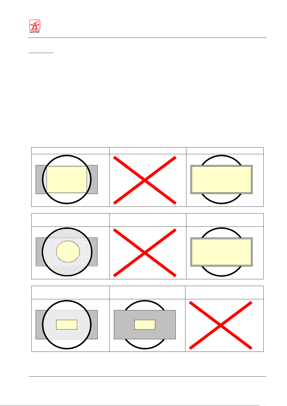
OPERATOR'S MANUAL OPERA T
August 2020
Page 61/135
Fluoroscopy (004)
Radiography (004)
Fluoroscopy with collimation of
the iris in reduction only (004)
Radiography (004)
Fluoroscopy with collimation in
reduction (004)
Radiography (004)
GENERAL MEDICAL MERATE S.P.A. CODE 62235 - REVISION 13
Setting 004
COLLIMATION APERTURE WITH THE IRIS SHUTTERS ON THE FILM SIZE SELECTED IN RADIOGRAPHIC MODE,
AND COLLIMATION APERTURE WITH THE PERPENDICULAR SHUTTERS AT THE FILM SIZE SELECTED IN
RADIOGRAPHIC MODE IF NOT COLLIMATED (the iris always opens in radiographic mode at the film size whilst
the perpendicular diaphragm opens in radiographic mode at the film size only if it was not collimated in
fluoroscopic mode)
In Radiographic mode:
If the size of the perpendicular side is not reduced using the joystick (61) before the radiographic phase:
The parallel side remains stationary in the previously selected position.
The perpendicular side remains on the film size (maximum allowed aperture)
The iris, if present, even if collimated, opens on the film size (maximum allowed aperture).
If the size of the perpendicular side is reduced using the joystick (61) before the radiographic phase:
The parallel side remains stationary in the previously selected position.
The perpendicular side remains stationary in the previously selected position.
The iris, if present, opens on the film size (maximum allowed aperture) even if previously collimated.
Page 66
OPERATOR'S MANUAL OPERA T
August 2020
Page 62/135
The Stop in horizontal position function, where available, can be enabled and configured during
the installation phase.
When this function is disabled, automatic stop of the tilting of the table in the horizontal
position is foreseen.
55
56
With table tilting wider than ±85° and X-ray group rotated (not centred on the SFD or detector ),
controlling the vertical position of the stand (centering), if this occurs with the stand moving
downwards the movement will stop at 140cm from the floor. It is necessary to release it and
repeat the command to continue with the movement. The movement will be enabled again at
minimum speed.
GENERAL MEDICAL MERATE S.P.A. CODE 62235 - REVISION 13
5.23.3. Bucky Mode (Push-button 54 enabled – LED ON)
FLUOROSCOPY: the system ALWAYS returns to automatic or semi-automatic collimation.
RADIOGRAPHY: collimation according to the cassette size/division in the SFD and examination table, without
using fluoroscopy, in Bucky mode, the diaphragm opens on the radiography size selected the moment in
which the cassette holder carriage reaches the parking position; later on it is possible to perform collimation
in reduction using the joystick (61) or the collimator knob. In the event of a division change, the diaphragm
will move to the new selected radiographic size.
In any case, the X-ray field in radiographic mode will always remain the same as the previously set collimation
size.
5.24. Stop in the horizontal position
Normal condition: during tilting, the table stops automatically in a horizontal position and the push-button
(55) is OFF and disabled.
It is possible to press the push-button (55) to select whether or not to disable the automatic stop function: the
LED will come ON.
5.25. Stand vertical position
Press this push-button (56) to restore the vertical position of the stand after the execution of oblique
incidences, the LED will come ON as soon as it reaches the vertical position.
Page 67
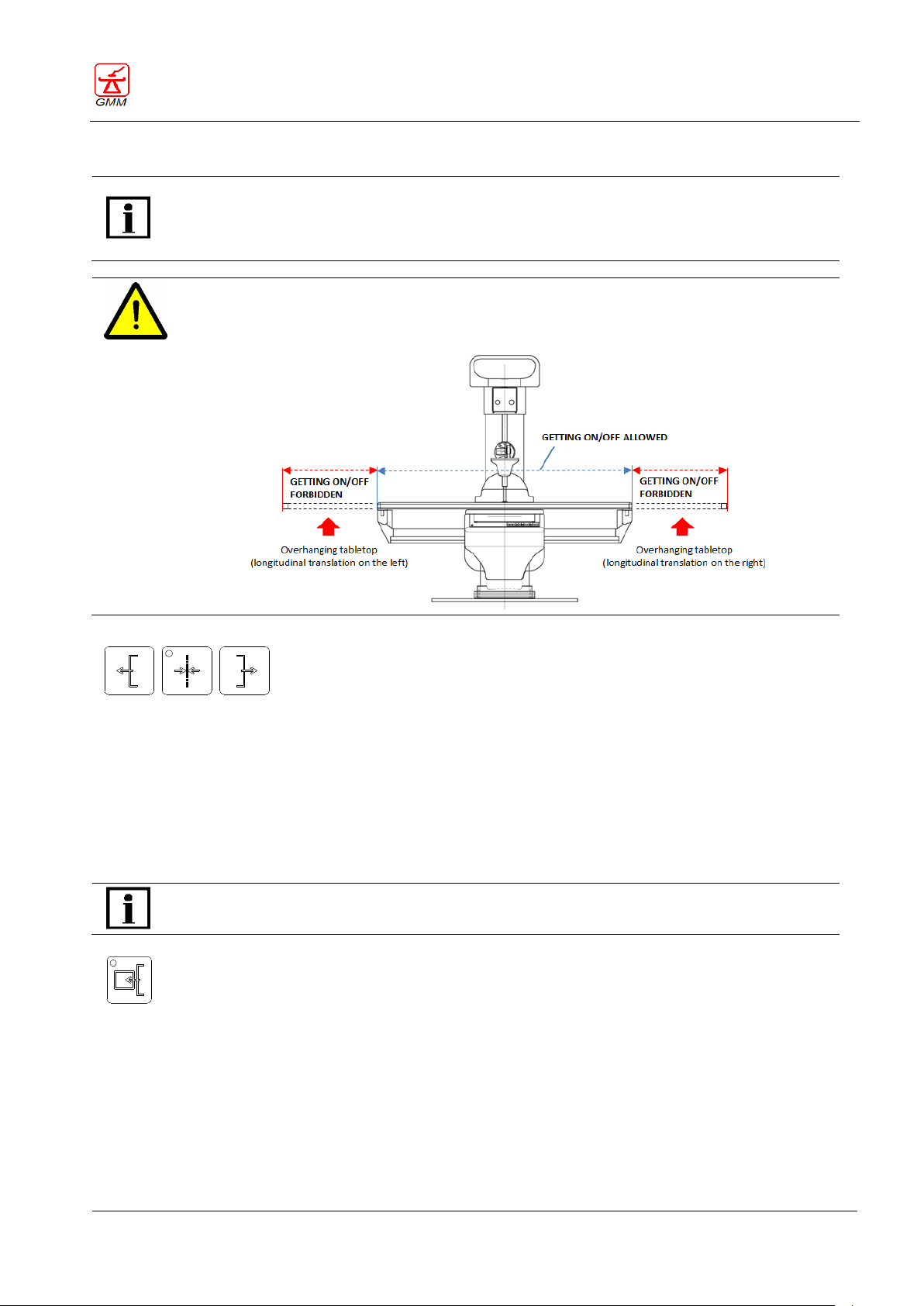
OPERATOR'S MANUAL OPERA T
August 2020
Page 63/135
The Tabletop longitudinal displacement commands, where installed, can be enabled and
configured and paired to tables with this option.
The tabletop can move symmetrically or asymmetrically depending on the table configuration
and the tabletop model.
WARNING
If longitudinal displacement of the tabletop is performed to the right or left, it is prohibited to
allow the patient to get on/off the tabletop from the overhanging side (see figure below).
57
58
59
The Cassette holder IN-OUT command, where installed, is paired to examination tables with
this option.
60
GENERAL MEDICAL MERATE S.P.A. CODE 62235 - REVISION 13
5.26. Tabletop longitudinal displacement
The lateral push-buttons (57 and 59) control the tabletop longitudinal displacement:
The lateral push button (57) moves the table top towards the left.
The lateral push button (59) moves the table top towards the side.
The central push-button (58) is used to place the tabletop in its original centered position. As soon as the
tabletop reaches the central position, the push button LED will come ON.
5.27. Cassette holder IN-OUT
This push-button (60) alternately controls the cassette holder IN-OUT function in the spot film device; the LED
will come ON to indicate the cassette holder OUT condition.
The display indicates the number of available exposures and will switch off if the radiographic cassette is
not inserted or the relative cassette holder is in the OUT position.
Page 68
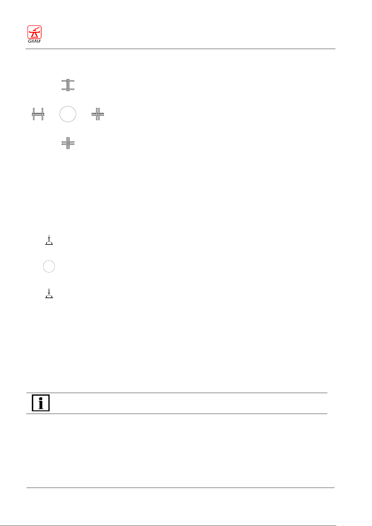
OPERATOR'S MANUAL OPERA T
August 2020
Page 64/135
61
62
Enabling the tomography or stitching command will automatically raise the compressor.
GENERAL MEDICAL MERATE S.P.A. CODE 62235 - REVISION 13
5.28. Diaphragm collimation
Using the joystick (61), it is possible to open and close the internal collimator diaphragms.
Push the joystick forwards to open the longitudinal diaphragms.
Push the joystick backwards to close them.
Push the joystick to the left to open the transversal diaphragms.
Push the joystick to the right to close them.
5.29. Compressor
The tabletop is equipped with a motorized compressor, enabling the pre-adjustment of the compression
pressure. The compressor movement is enabled using a joystick type lever (62):
Tip the lever forwards to lower the compressor and enable compression.
Tip the lever backwards to raise the compressor again.
When the compressor device is in compression there will be an inhibition of the following movements:
tabletop transversal displacement
tabletop longitudinal displacement
spot film device stand unit inclination and transversal displacement
focal distance decrease
Page 69
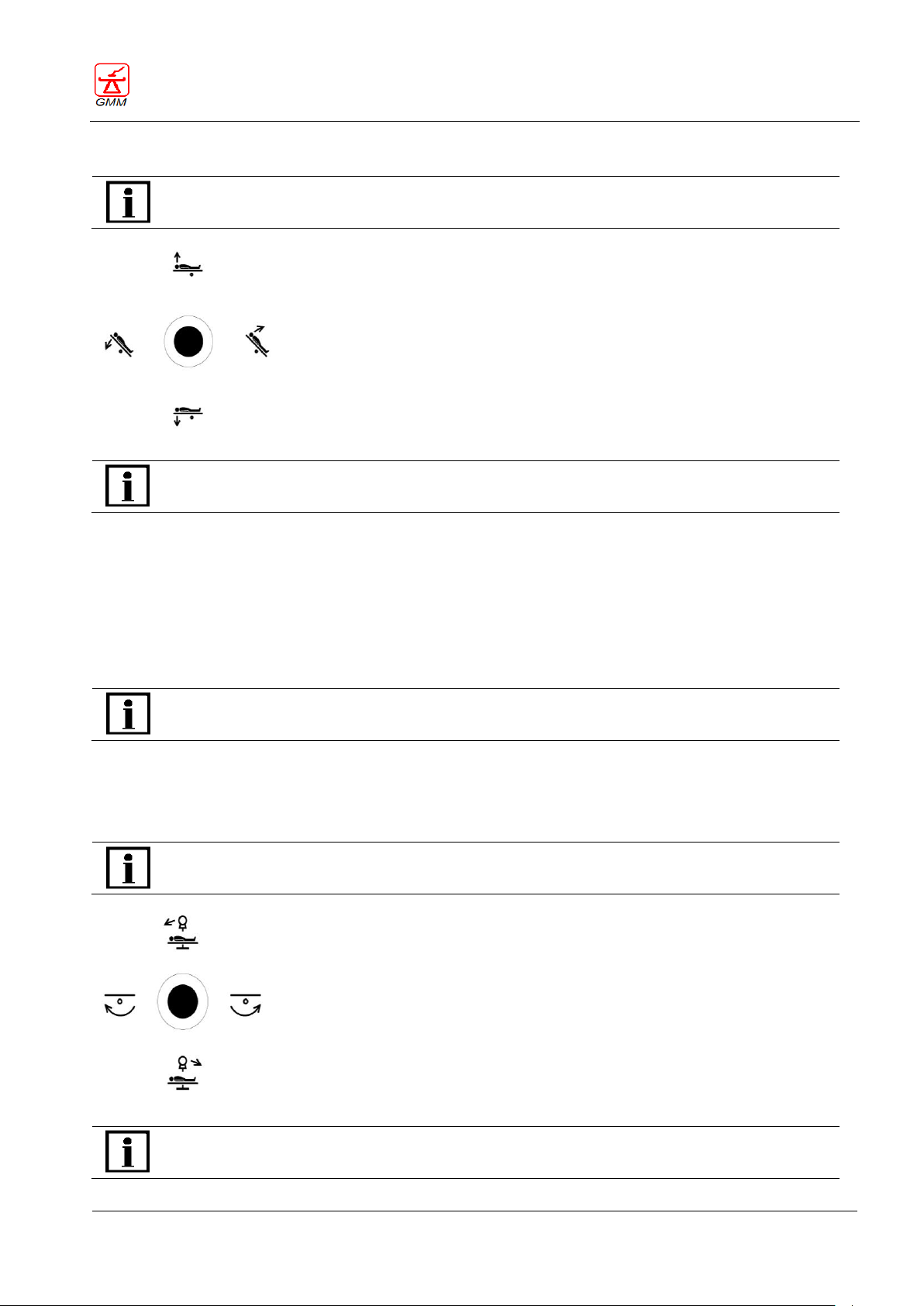
OPERATOR'S MANUAL OPERA T
August 2020
Page 65/135
The Tabletop elevation function, where installed, is paired to examination tables with this
option.
63
In order to use the joystick (63) to control the movements, it is necessary to move the lever and
simultaneously press the “enable movements” button, which is positioned on the lever itself.
When this function is available, the elevation or lowering of the tabletop are only possible when
the table is in the horizontal position.
The Footrest rotation function, where installed, is paired to tables with this option.
64
In order to use the joystick (64) to control the movements, it is necessary to move the lever and
simultaneously press the “enable movements” button, which is positioned on the lever itself.
GENERAL MEDICAL MERATE S.P.A. CODE 62235 - REVISION 13
5.30. Tabletop elevation and tilting
5.30.1. Tabletop tilting
Pushing the joystick to the right will tilt the table to a vertical position (+90°).
Pushing the joystick to the left will tilt the table to the Trendelenburg or vertical position (-90°).
The movement speed varies according to the inclination degree of the joystick.
5.30.2. Tabletop elevation
pushing the joystick forwards will elevate the tabletop.
pushing the joystick backwards will lower the tabletop.
5.31. X-ray tube stand incidence and footrest rotation
Page 70
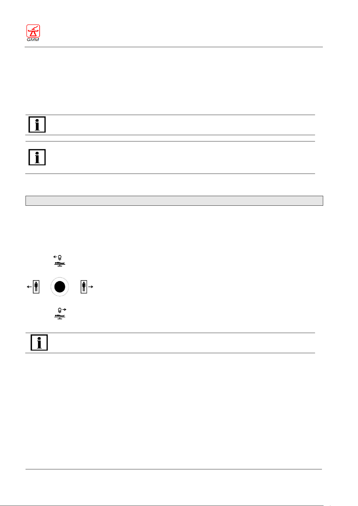
OPERATOR'S MANUAL OPERA T
August 2020
Page 66/135
It is possible to enable the stand incidence command and the longitudinal patient scanning
command simultaneously.
With the table tilting wider than ±85° and X-ray group rotated (not centered on SFD or detector),
by driving the oblique incidence downwards, the movement will stop at 140 cm from the floor. It is
necessary to release it and repeat the command to continue the movement. The movement will
be enabled again at minimum speed.
65
In order to use the joystick (65) to control the movements, it is necessary to move the lever and
simultaneously press the “enable movements” button, which is positioned on the lever itself.
GENERAL MEDICAL MERATE S.P.A. CODE 62235 - REVISION 13
5.31.1. X-ray tube stand incidences
Pushing the joystick forward will move the X-ray tube stand to the left, with subsequent rotation of the
tube enabling the execution of left oblique incidences.
Pushing the joystick backwards will move the X-ray tube stand to the right, with subsequent rotation of
the tube enabling the execution of right oblique incidences.
The tube stand can be inclined up to an angle of 40° and the incidence angle is visualised on the display.
5.31.2. Footrest rotation
Please refer to the "Accessories" chapter for instructions on how to install the footrest correctly.
The footrest rotation command allows rotation of the footrest with the tabletop in a vertical position (±90°):
Pushing the lever (64) to the right will move the footrest clockwise;
Pushing the lever (64) to the left will move the footrest counter clockwise;
5.32. Control of the patient scanning movements
The movement speed varies according to the inclination degree of the control lever. This allows the operator
to change the scanning speed according to the operational needs, i.e. it will be possible to increase the speed
if long movements are to be executed and then decrease the speed when approaching the area to be
diagnosed in order to achieve accurate centering.
The movements have been programmed to achieve a “topographic” correspondence with the image
displayed on the monitor.
Pushing the joystick to the right will achieve lateral displacement of the tabletop towards the internal
side, corresponding to screen image shifting to the right.
Pushing the joystick to the left will achieve lateral displacement of the tabletop towards the external side,
corresponding to screen image shifting to the left.
Pushing the joystick forwards will achieve the displacement of the I.I intensifier X-ray tube stand group
towards the left side of the longitudinal axis, corresponding to screen image shifting upwards.
Page 71
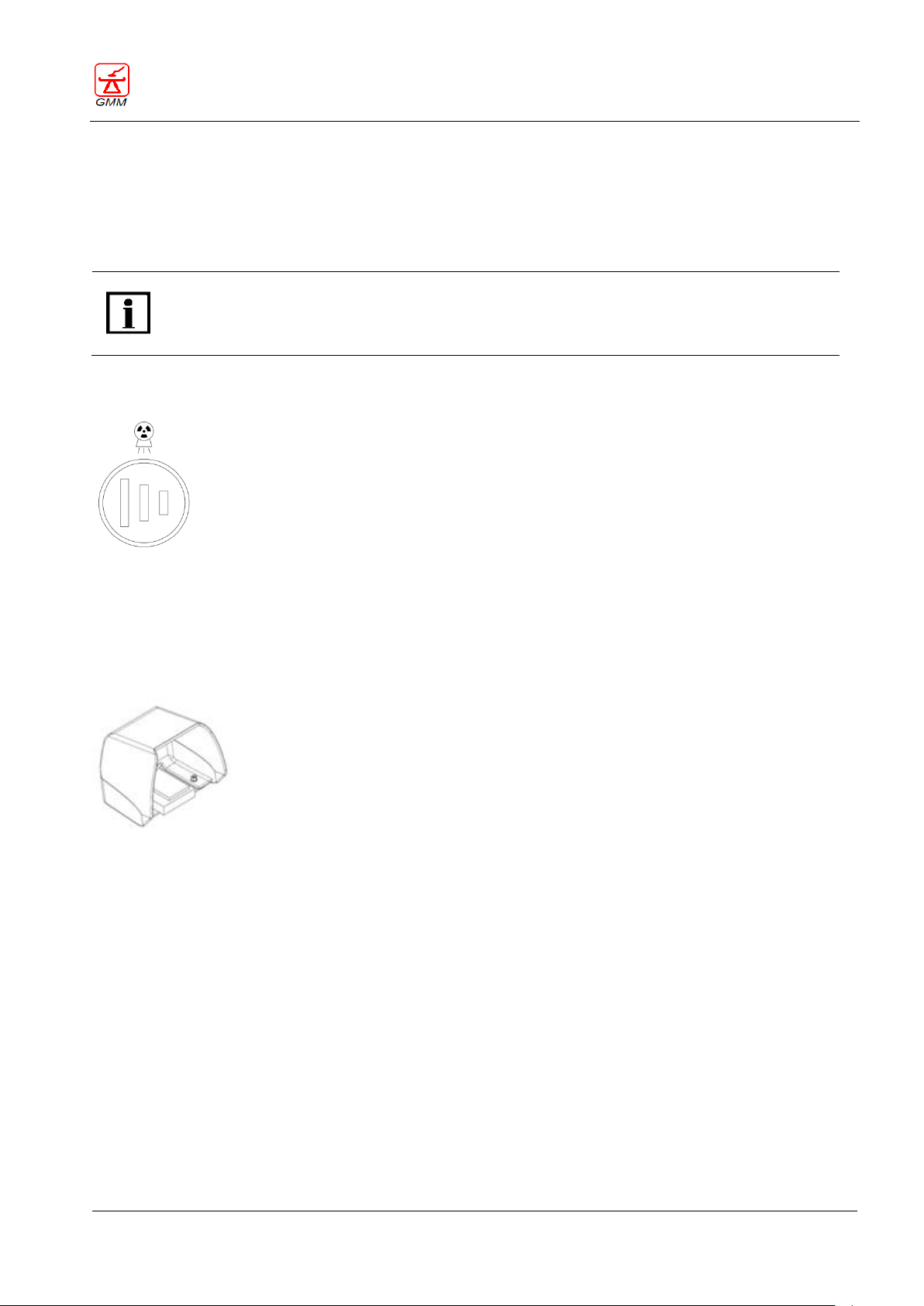
OPERATOR'S MANUAL OPERA T
August 2020
Page 67/135
With the table tilting wider than ±85° and X-ray group rotated (not centred on the SFD or
detector ), by driving the oblique incidence downwards, the movement will stop at 140 cm from
the floor. It is necessary to release it and repeat the command to continue the movement. The
movement will be enabled again at minimum speed.
66
67
GENERAL MEDICAL MERATE S.P.A. CODE 62235 - REVISION 13
Pushing the joystick towards the operator (backwards) will achieve the displacement of the I.I.-X-ray tube
stand group towards the right side of the longitudinal axis, corresponding to screen image shifting
downwards.
When the movements approach their maximum extensions, the tilting speed automatically and gradually
decreases in order to prevent them coming to an abrupt stop.
5.33. X-Ray exposure
The X-Ray exposure command is executed by means of a double-click push-button (66).
The first click of the push-button enables the Radiography Preparation, while the second click (deeper)
enables the X-Ray, tomographic or stitching exposure.
5.34. Fluoroscopic exposure
The fluoroscopic exposure command is executed by means of the pedal (67).
Page 72
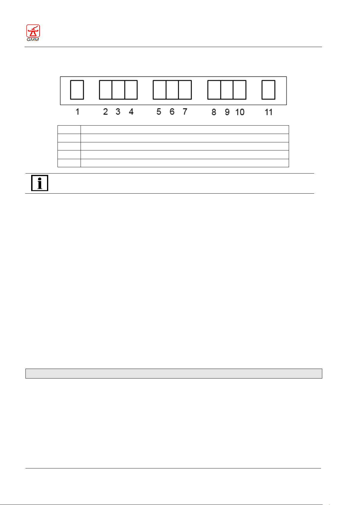
OPERATOR'S MANUAL OPERA T
August 2020
Page 68/135
1
Acquisition frequency or image review function
2-3-4
Layer height
5-6-7
Adjustable tabletop height / Tilting angle
8-9-10
Stand angle
11
Available exposures (optional)
Normal visualization on the display is inhibited when an error code or power off occur.
GENERAL MEDICAL MERATE S.P.A. CODE 62235 - REVISION 13
6. VISUALIZATION ON THE MAIN CONSOLE DISPLAY
6.1. Acquisition frequency or image review function
The display screen (1) displays the following information:
It indicates movement inhibition when there is an external limitation (ceiling, floor, walls etc). As soon as
an inhibition is triggered, the display will start flashing.
When using analog systems with memory function, the display screen (1), displays the value related to
the acquisition function or image review.
6.2. Displaying layer height and error codes
The display screen (2,3,4) displays a variety of information depending on the tabletop condition.
6.2.1. Displaying the layer height
The display screen displays the following layer information:
The default layer height when the equipment is switched on =125mm
The layer height in millimetres above the tabletop (adjustment of the layer height from 0 to 330 with
increase-step of 1 millimetre)
The layer height in millimetres including the automatic increase in tomography
6.2.2. Errors codes/ equipment condition
The display also indicates any error codes.
Please refer to the “Error code list” chapter for a complete list of the codes.
6.3. Displaying the tilting angle and elevation millimetres
The display screen (5,6,7) displays a variety of information depending on the tabletop condition.
With a tilting angle other than zero, or when there is no "tabletop elevation" option, the display screen
will display the tilting angle.
With a tilting angle equal to zero, and the "tabletop elevation" option, the display screen will display the
tabletop elevation in millimetres.
If a conventional spot film device is being used, with cassette parked, by pressing and holding the selected
cassette division push-button (one of the 43, 44, 45, 46, 47 or 48 push-buttons) the display screen will
display the cassette parallel size.
Page 73
OPERATOR'S MANUAL OPERA T
August 2020
Page 69/135
The display (11) is only available on systems equipped with conventional or hybrid spot film
device.
GENERAL MEDICAL MERATE S.P.A. CODE 62235 - REVISION 13
6.4. Displaying the incidence angle
The display screen (8,9,10) will display a variety of information depending on the tabletop condition:
Normally the incidence angle
During a tomography function, the selected tomographic angle
The number of steps available (max four) is displayed during the peristepping function.
If a conventional spot film device is being used, with cassette parked, by pressing and holding the selected
cassette division push-button (one of the 43, 44, 45, 46, 47 or 48 push-buttons) the display screen will
display the cassette perpendicular size.
6.5. Displaying the available exposures
The display (11) indicates the number of available exposures and will switch off if the radiographic cassette is
not inserted or the cassette holder is in the OUT position.
Page 74
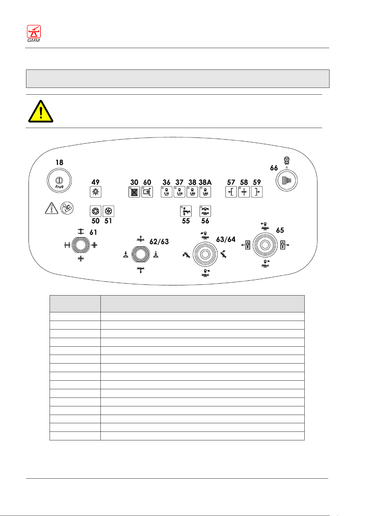
OPERATOR'S MANUAL OPERA T
August 2020
Page 70/135
WARNING
The main console, the keyboard and secondary console (in room) are enabled simultaneously.
DO NOT RUN SIMULTANEOUS CONTROLS FROM DIFFERENT POSITIONS.
Park the secondary console outside the table displacement area when not in use.
Push-button
group
Secondary console (in room) control function description
18
Emergency STOP push-button
30
Grid parking
36-37-38-38A
Focal distance selector
49
Collimator lamp
50-51
Iris diaphragms
55
Stop in the horizontal position
56
Stand vertical position
57-58-59
Tabletop longitudinal displacement
60
Cassette holder in - out
61
Diaphragm collimation
62
Compressor
63
Tabletop elevation and tilting
64
X-ray tube stand incidences
65
Control of the patient scanning movements
66
X-Ray exposure
GENERAL MEDICAL MERATE S.P.A. CODE 62235 - REVISION 13
7. COMMAND FUNCTIONS OF THE SECONDARY CONSOLE (OPTIONAL)
Please refer to the “Command functions of the main control console” chapter for the description of the
push-buttons and relative functions.
Page 75
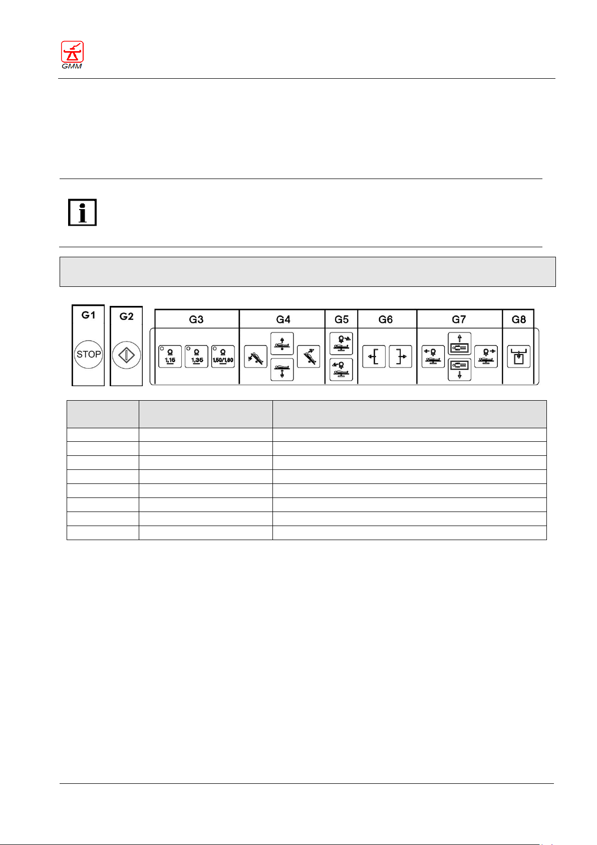
OPERATOR'S MANUAL OPERA T
August 2020
Page 71/135
In order to enable control the movements via the remote keyboard (onboard machine control
panel) it is necessary to press the desired movement push-button and simultaneously the
“enable movements” push-button (G2), which is positioned to the remote keyboard.
The only movement for which the simultaneous pressing of the "enable movements" pushbutton is not required is the cassette holder IN/OUT function.
Push-button
group
Associated to console
push-buttons
Description of the functions controlled from the
examination table
G1
18
Emergency STOP push-button
G2
-
Enable movements from the examination table
G3
36-37-38-38A
Focal distance selector
G4
63
Examination table tilting and elevation (optional)
G5
56.64
X-ray tube stand incidences
G6
57-58-59
Longitudinal tabletop translation
G7
65
Control of the patient scanning movements
G8
60
Cassette in - out
GENERAL MEDICAL MERATE S.P.A. CODE 62235 - REVISION 13
8. FUNCTIONS CONTROLLED FROM THE EXAMINATION TABLE
Certain functions are available on the examination table-side control panel located on the front cover of the
Spot Film Device.
Repeating these commands is useful during centering manoeuvres or to prepare the tabletop near the
patient.
Please refer to the “Command functions of the main control console” chapter for the description of the
push-buttons and relative functions.
8.1. Focal distance selector
(G3)
These push-buttons allow the operator to choose from three or four different focal distances by simply
pressing the relevant push-button.
If you release the push-button before the correct distance is reached, the three push-button LEDs will flash
and all movements will come to a stop. (There is an optional version where it is possible to set intermediate
focal distances during the installation phase).
8.2. Tilting and elevation (optional) of the tabletop
(G4)
Press the right or left push-buttons to tilt the table to the Trendelenburg and/or vertical position.
Table elevation is archived by pressing the top or bottom push-buttons. (Optional function).
Page 76
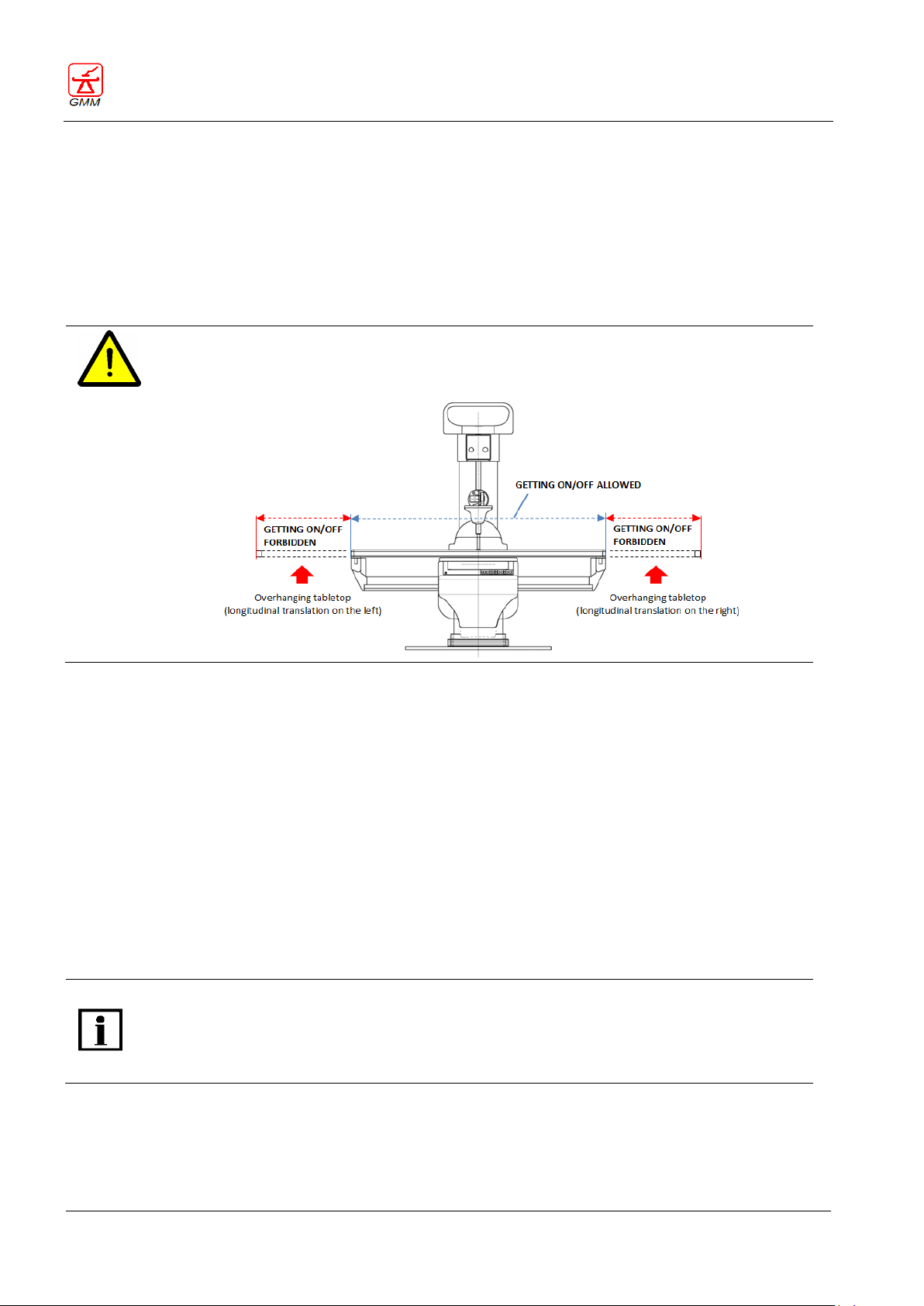
OPERATOR'S MANUAL OPERA T
August 2020
Page 72/135
WARNING
If longitudinal displacement of the tabletop is performed to the right or left, it is prohibited to
allow the patient to get on/off the tabletop from the overhanging side (see figure below).
With the table tilting wider than ±85° and X-ray group rotated (not centered on SFD or detector),
by driving the oblique incidence downwards, the stand centering, longitudinal scan and table
displacement will stop at 140 cm from the floor. It is necessary to release it and repeat the
command to continue the movement. The movement will be enabled again at minimum speed.
GENERAL MEDICAL MERATE S.P.A. CODE 62235 - REVISION 13
8.3. Oblique incidences
(G5)
These two push-buttons allow the execution of the oblique incidences up to a maximum of 40°. The top pushbutton commands the displacement of the stand to the right, while the bottom push-button commands the
displacement of the stand to the left. The displacement will come to a halt each time the stand reaches the
vertical position. It is necessary to release the push-button and press it again to continue the incidence.
8.4. Longitudinal tabletop displacement (optional)
(G6)
The two remaining push-buttons control the longitudinal displacement of the tabletop. The displacement will
come to a halt each time the examination table reaches the central position. It is necessary to release the
push-button and press it again to continue the scan.
When the examination table is tilted, press the left or right push-button to lower the tabletop towards the
floor (step by step mode), in order to make it easier for patients with motor difficulties to climb onto the
patient footrest.
8.5. Patient scanning
(G7)
These four push-buttons control the patient scanning movements with displacement of the "Stand/spot film
device" group (push-buttons on the left and on the right) and the transversal displacement of the tabletop
(push-buttons on top and bottom).
8.6. Cassette holder IN-OUT
(G8)
The push-button alternately controls the IN and OUT functions of the spot film device cassette holder.
Page 77
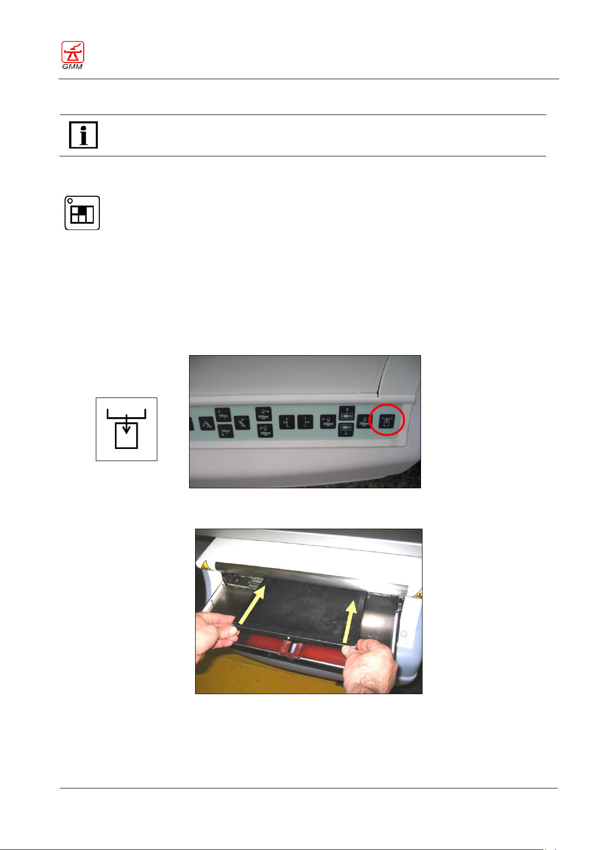
OPERATOR'S MANUAL OPERA T
August 2020
Page 73/135
The following procedure is valid only for equipment with conventional SFD.
Before opening the SFD cassette holder, you must have previously selected the SFD receptor
(Spot Film Device) by pressing the related push-button on the control console.
31
Cassette
INSERT/EJECT
GENERAL MEDICAL MERATE S.P.A. CODE 62235 - REVISION 13
9. INSERTING THE CASSETTE IN THE SFD
9.1. Selecting conventional radiography
Select conventional radiography (if available and/or enabled) and/or select the generator receptor
associated to the conventional radiography selection.
9.2. Procedure for inserting the cassette
Press the push-button controlling the opening of the SFD cassette-holder: this push-button is placed on
the console or next to the cassette-holder itself
Insert the cassette by pushing the two external edges
Page 78
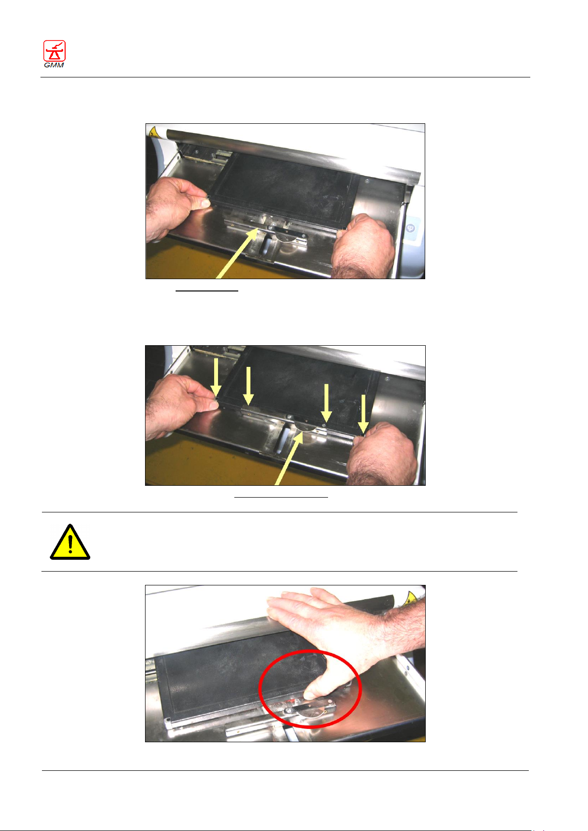
OPERATOR'S MANUAL OPERA T
August 2020
Page 74/135
External guide
“Right-Left” indicator
WARNING
Inserting the cassette incorrectly could lead to squashing of fingers!
GENERAL MEDICAL MERATE S.P.A. CODE 62235 - REVISION 13
Position the cassette on the tray when it has exceeded the external tray guide.
Slot the cassette into the external guide paying attention to the position of the fingers.
Adjust the "right-left" indicator where necessary.
Page 79
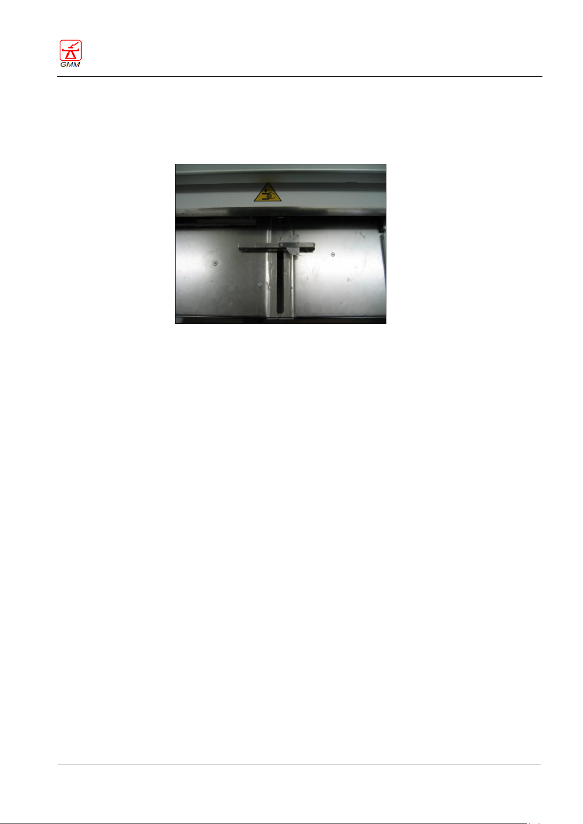
OPERATOR'S MANUAL OPERA T
August 2020
Page 75/135
GENERAL MEDICAL MERATE S.P.A. CODE 62235 - REVISION 13
9.3. Cassette right/left marker (if available)
There is a device fitted inside the SFD cassette holder used to mark the radiographic images with the letter R
(right) and L (left). This device is enabled manually and its correct functioning also depends on the type of
collimation the user intends to perform.
Page 80
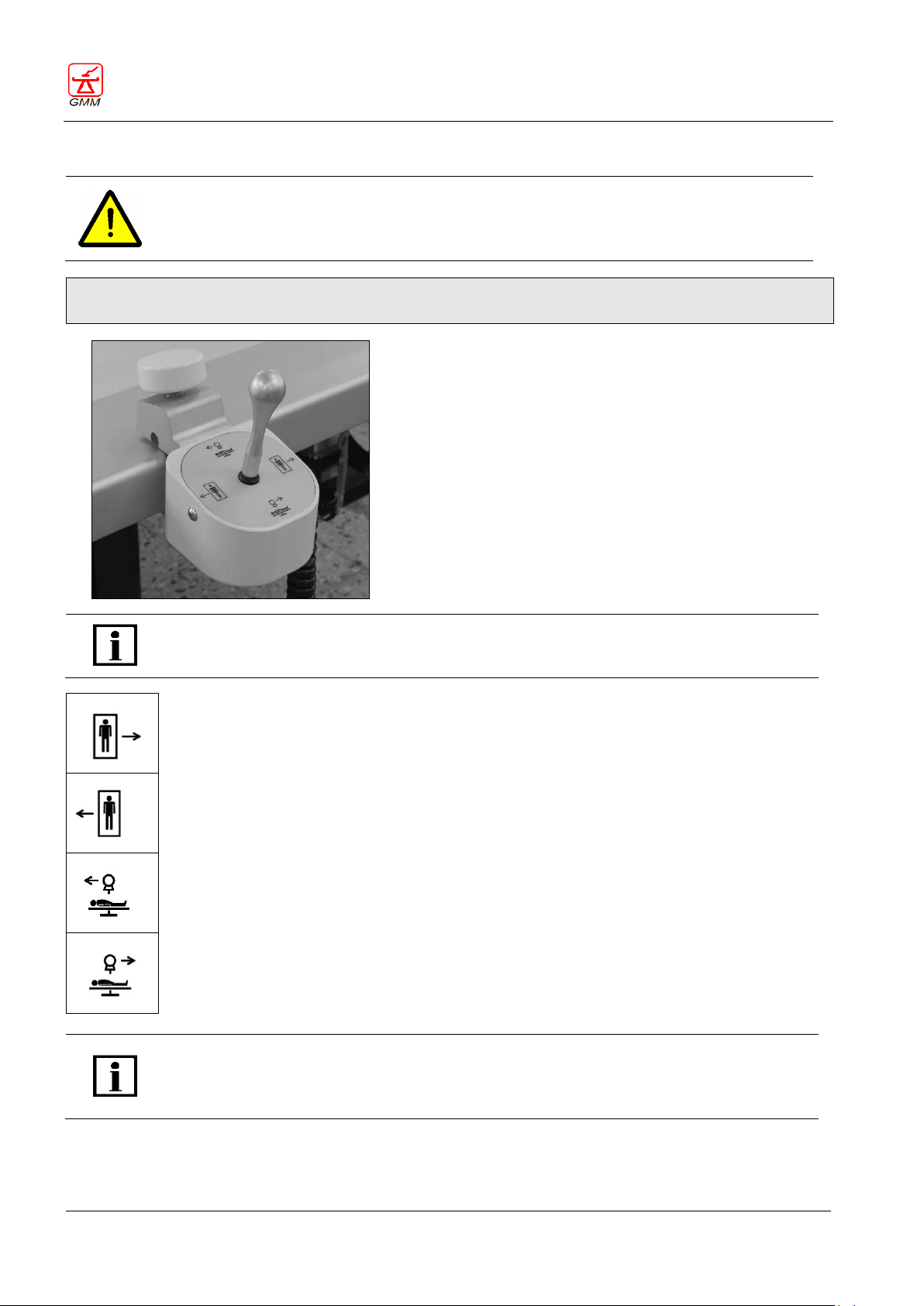
OPERATOR'S MANUAL OPERA T
August 2020
Page 76/135
WARNING
Incorrect installation of the on-board console with joystick can cause damage to patients,
operators and equipment.
The optional on-board joystick controls the patient scanning
displacement:
Move the joystick up or down to effect longitudinal
patient scanning through the positioning of the
stand/spot film device.
Move the joystick to the left or right to effect
transversal patient scanning through the positioning of
the tabletop in a transverse position.
The movements were programmed so that a “topographic”
correspondence is obtained compared with the image
showed on the monitor.
In order to use the on-board joystick to control the table displacement, it is necessary to
move the lever and simultaneously press the “enable movements” push-button which is
positioned near the remote keyboard (on-board control panel).
Pushing the joystick to the right will achieve lateral displacement of the tabletop towards the
internal side, corresponding to screen image shifting to the right.
Pushing the joystick to the left will achieve lateral displacement of the tabletop towards the
external side, corresponding to screen image shifting to the left.
Pushing the joystick forwards will achieve the displacement of the I.I.-X-ray tube stand group
towards the left side of the longitudinal axis, corresponding to screen image shifting
upwards.
Pushing the joystick towards the operator (backwards) will achieve the displacement of the
I.I.-X-ray tube stand group towards the right side of the longitudinal axis, corresponding to
screen image shifting downwards.
With table tilting wider than ±85° and X-ray group rotated (not centred on the SFD or
detector), by driving the oblique incidence lower the movement will stop at 140 cm from the
floor. It is necessary to release it and repeat the command to continue the displacement
operations. Displacement will be enabled again at minimum speed.
GENERAL MEDICAL MERATE S.P.A. CODE 62235 - REVISION 13
10. ON-BOARD CONTROL CONSOLE WITH JOYSTICK (OPTIONAL)
Please refer to the “Using the accessories” chapter for installation instructions of the on-board console with
joystick.
Page 81
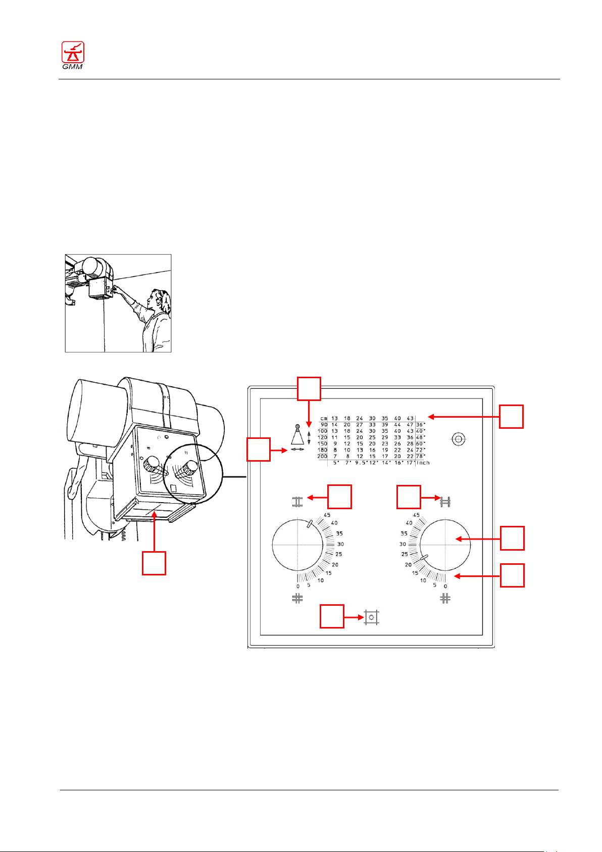
OPERATOR'S MANUAL OPERA T
August 2020
Page 77/135
D B E
F
A
L
R
G
C
GENERAL MEDICAL MERATE S.P.A. CODE 62235 - REVISION 13
11. COLLIMATOR
11.1. Lighting up of the luminous beam
Press push button (A) on the collimator.
The luminous beam will remain lit on for about 30 seconds simulating the dimension of the X-ray field. It
will switch off automatically.
The cross (G) indicates the position of the central radiation.
Average illumination is not less than 160 LUX; edge contrast ratio is minimum four to one (4:1)
The field size at various Focus-Film Distances (FFD) is shown by the dial indicators on the front of the
collimator.
Collimator provided with control devices for the manual limitation of the X-ray field
Page 82
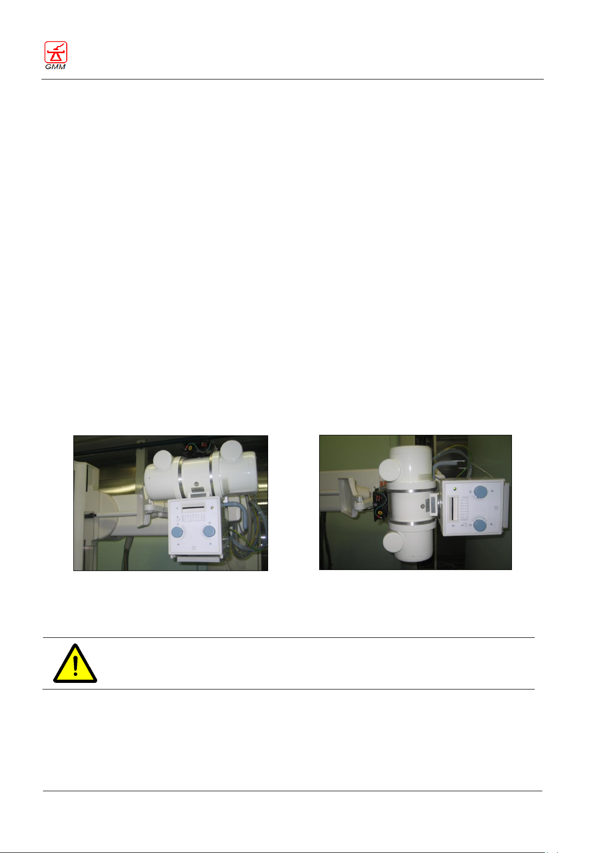
OPERATOR'S MANUAL OPERA T
August 2020
Page 78/135
+90°
+180°
WARNING
If you rotate the tube or use the accessory provided for external radiographs the radiation
beam will extend beyond the primary protective shielding.
GENERAL MEDICAL MERATE S.P.A. CODE 62235 - REVISION 13
11.2. Limiting the X-ray beam field
Turn the adjustment knobs (B) on the collimator:
- The knob on the left (L)commands the diaphragms in the width direction (parallel diaphragm) turn
clockwise to close them and counter clockwise to open them.
- The knob on the right (R) commands the diaphragms in the height direction (perpendicular diaphragms):
turn clockwise to open them and counter clockwise to close them.
11.3. DFR technique
This technique is present if the DFR push button (14) (on the main consol panel) has been selected.
It is possible to change the X-ray field within the limits of the I.I. size that was previously selected by means of
the push-buttons (1, 2, 3, 4) (on themain console panel)
11.4. X-ray cassette technique
Below the adjustment knobs (B) there are special graduated scales (C): at each segment it corresponds a
collimator aperture over the cassette or over the image intensifier related to focal distance frontal panel
table (D).
The table on the front panel shows the number to set with the knobs. The number to set is read by crossing
the FFD in use cm or in inch (vertical arrow E ) with the cassette size in cm on inches (horizontal arrow F).
Move the knob index to place it on the scale value corresponding to the requested measure/value.
11.5. X-ray field adjustment for “External Radiographs”
Place the empty cassette-holder in its parking position (outside the field) or command the tube rotation to
18°/90°/180°.
Follow the same above-specified procedure. You can modify the X-ray field up to the mechanical limits of the
adjustment area of the collimator
Page 83
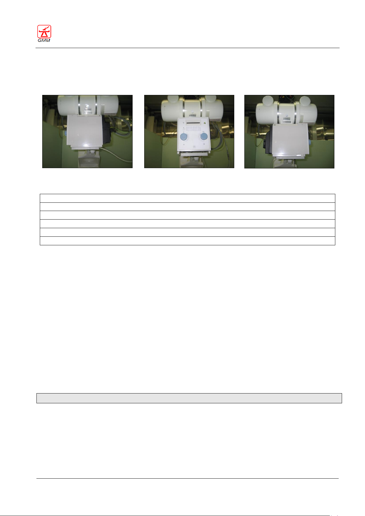
OPERATOR'S MANUAL OPERA T
August 2020
Page 79/135
Collimator rotated to the left
Centred collimator
Collimator rotated to the right
Motorized collimator with rectangular field
Motorized collimator with rectangular field and Iris
Motorized collimator with rectangular field, Iris and motorized filters
Motorized collimator with rectangular field and motorized filters
Motorized collimator with rectangular field, Iris and manual filters *
Motorized collimator with rectangular field and manual filters *
GENERAL MEDICAL MERATE S.P.A. CODE 62235 - REVISION 13
11.6. Collimator manual rotation (90°) - if present
It is possible, depending on the needs, to rotate by hand the collimator to90°, as shown in the following
pictures.
11.7. Collimator type
* Available depending on the regulatory of Country of installation
The collimator, provided with luminous centering device, allows three adjustment modes:
- manual
- remote‐controlled from the control panel
- automatic, according to the cassette division, I.I. field, focus‐to‐film distance..
The collimator can be a rectangular field type or a rectangular‐iris fields type very useful with
digital system applications.
- Besides, as an option, are available a series of additional filters:
position 1: 1 mm Al + 0,1 mm Cu
position 2: 1 mm Al + 0,2 mm Cu
position 3: 2 mm Al
position 4: empty
- rotation feature for easy collimation of contact radiographies with cassette out of SFD (eg.:
extremities);
- more powerful lamp for brightness compensation of the luminous field due to the DAP
meter presence.
For further information on the collimator types, make reference to the relevant manuals.
Page 84
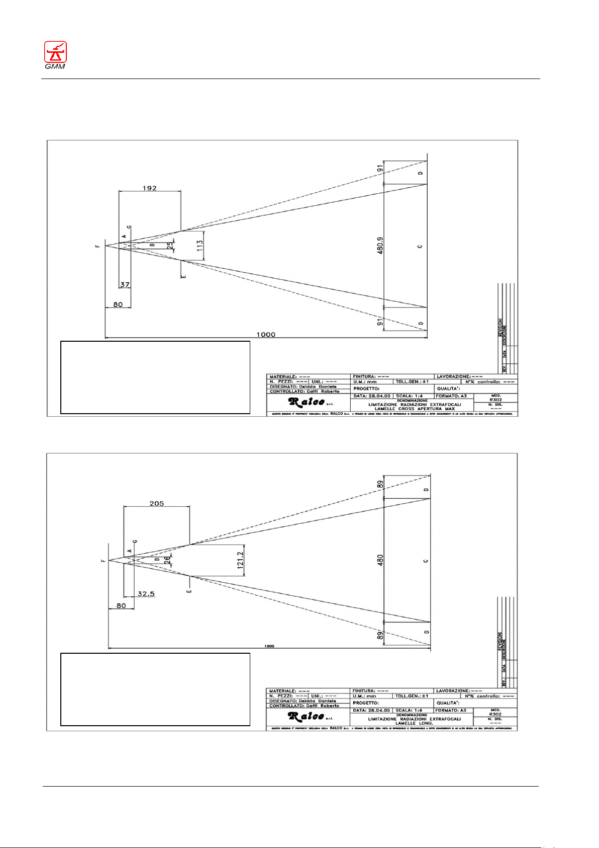
OPERATOR'S MANUAL OPERA T
August 2020
Page 80/135
F = Focus
A = Extra focal shutters
B = R302 collimator
C = Maximum field
D = Maximum stray radiation
E = Lead limitation
G = Upper cover
F = Focus
A = Extra focal shutters
B = R 302 collimator
C = Maximum field
D = Maximum stray radiation
E = Lead limitation
G = Upper cover
GENERAL MEDICAL MERATE S.P.A. CODE 62235 - REVISION 13
11.8. X-ray beams extra focal collimator radiations
R302 CROSS
R302 LONG
Page 85
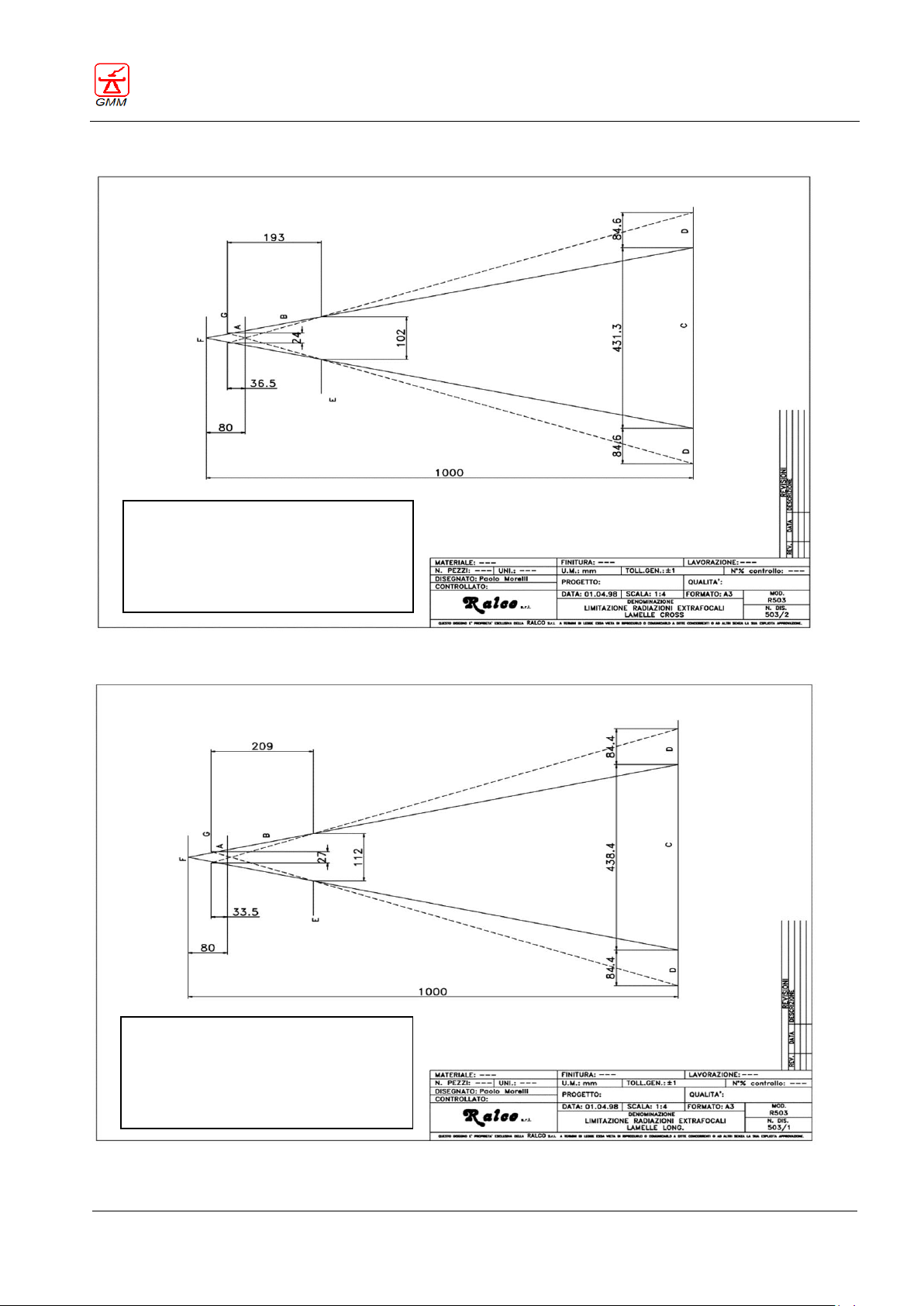
OPERATOR'S MANUAL OPERA T
August 2020
Page 81/135
F = Focus
A = Extra focal shutters
B = R 503 collimator
C = Maximum field 430 mm
D = Maximum stray radiation
E = Lead limitation
G = Upper cover
F = Focus
A = Extra focal shutters
B = R 503 collimator
C = Maximum field 430 mm
D = Maximum stray radiation
E = Lead limitation
G = Upper cover
GENERAL MEDICAL MERATE S.P.A. CODE 62235 - REVISION 13
R302 MLPI CROSS
R302 MLPI LONG
Page 86
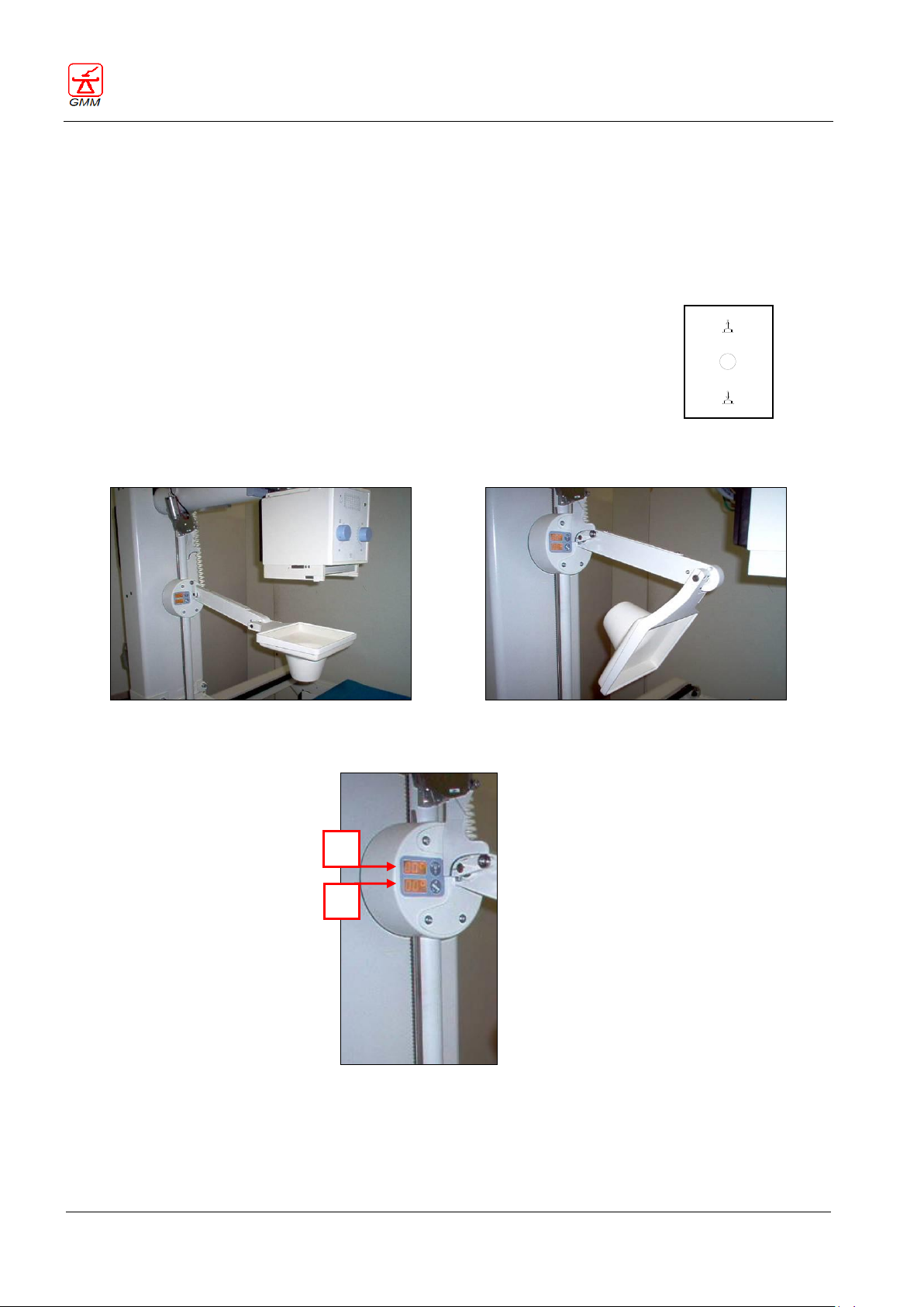
OPERATOR'S MANUAL OPERA T
August 2020
Page 82/135
The compressor reaches its parking position automatically.
By moving proper console joystick (push button 62),the compressor will reach
automatically the parking position at the end of its stroke.
Thanks to this function, to remove the compressor manually will not be necessary in
case it is an obstacle to equipment functions.
(62)
Compressor working position
Compressor parked position
Compressor display
1
2
GENERAL MEDICAL MERATE S.P.A. CODE 62235 - REVISION 13
12. COMPRESSOR
The remote-controlled compressor allows an effective though not traumatic palpation; the compression force
can be adjusted from 50 to 200 N.
A special consideration has been devoted to mechanical and electrical safeties, as well as safety against wrong
manoeuvres.
12.1. Automatic compressor parking
12.2. Compressor display
The display positioned on compressor support visualizes the following data:
- First display (1) visualizes the incidence angle, in addition during the tomographic exam it will visualize the
tomographic angle.
- Second display (2) visualizes the table tilting angle.
Page 87
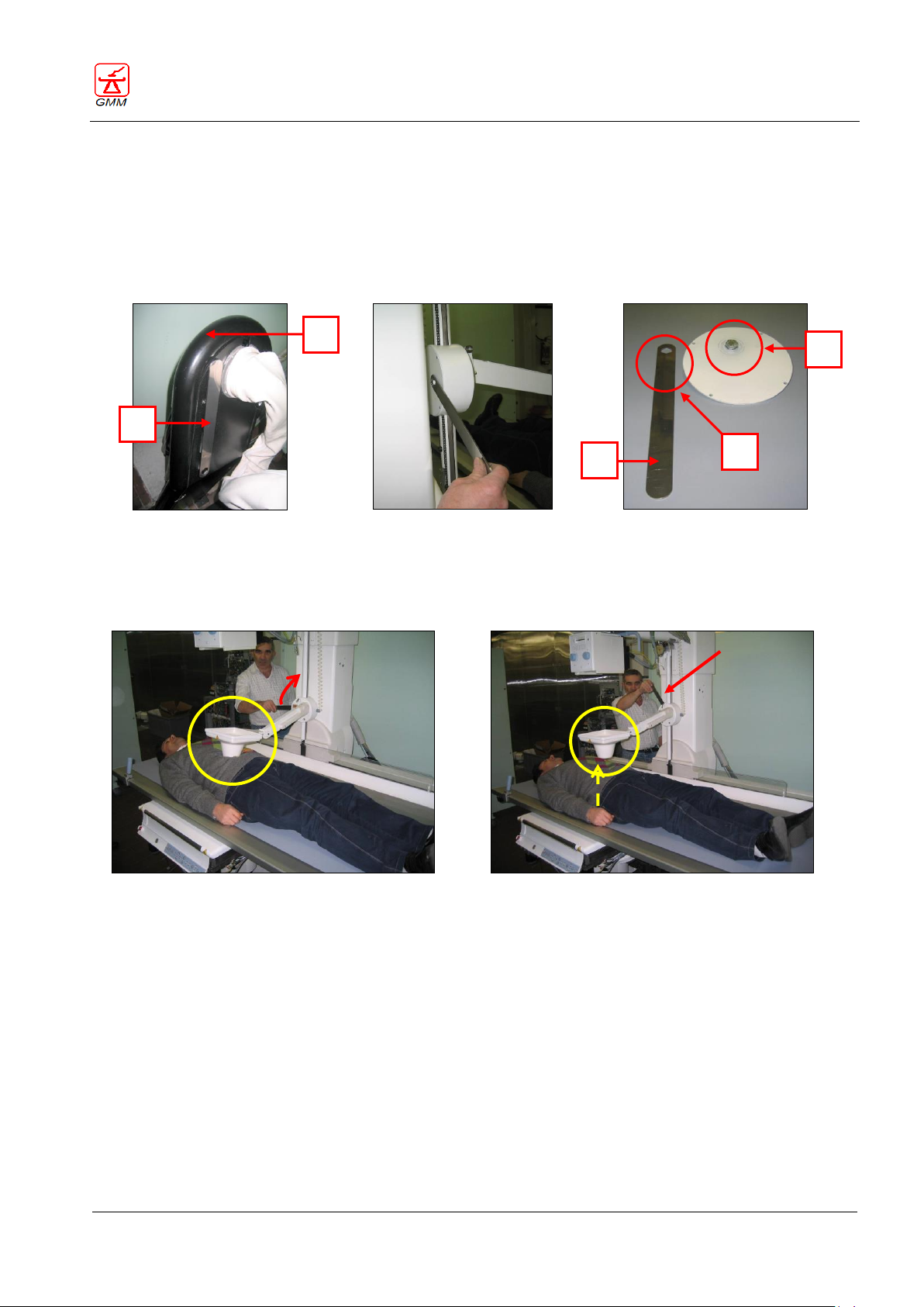
OPERATOR'S MANUAL OPERA T
August 2020
Page 83/135
Fig. 1
Fig. 2
Fig. 3
Fig. 4
Fig. 5
B B L H M
GENERAL MEDICAL MERATE S.P.A. CODE 62235 - REVISION 13
12.3. Manually removing the compressor
Should it be necessary to release the compressor manually, you shall execute the following steps:
Take the release lever [B] (Fig. 1 and Fig. 3) which is fixed on the cable-support turret [H] (Fig. 1) with
Velcro.
Insert the hexagon [M] of the release lever (Fig. 3 e Fig. 2) onto the screw [L] protruding from the back
cover (Fig. 3 e Fig. 2).
Lift the compressor by means of the lever [B] (Fig. 3) as shown in Fig. 4 e Fig. 5, by turning the lever
counter clockwise if you are standing behind the back side of the equipment.
Page 88
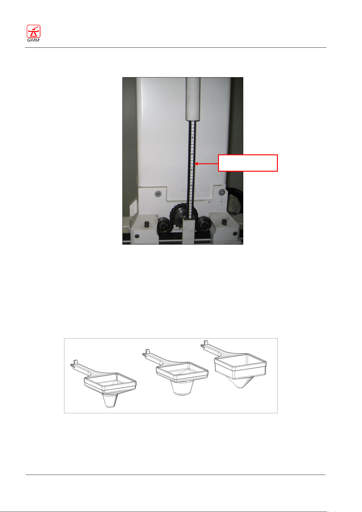
OPERATOR'S MANUAL OPERA T
August 2020
Page 84/135
Distance scale
GENERAL MEDICAL MERATE S.P.A. CODE 62235 - REVISION 13
12.4. Distance scale
For tables equipped with continuous variable focal distance, a distance scale is positioned on the compressor
column which allows for measuring the exact focal distance, upon releasing the related push button.
In addition the X- ray maximum fluoro dose value will be compensated related to focal distance choice.
12.5. Compressor with interchangeable cones (option)
As an option, an alternative compression system is available with three interchangeable cones of different
size (large, medium and small cap).
With this accessory the automatic parking feature is not available.
For assembling instructions of the interchangeable cones, see the chapter “Using the accessories”.
Page 89
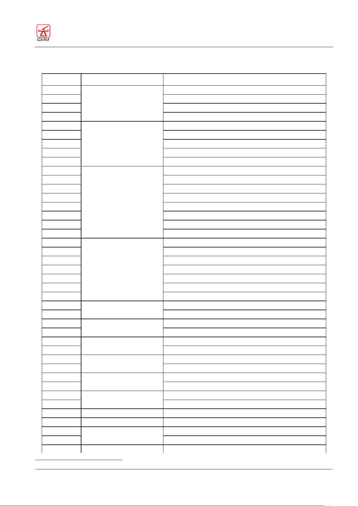
OPERATOR'S MANUAL OPERA T
August 2020
Page 85/135
CODE
TRANSMISSION
CAUSE
001
Tilting
Potentiometer
002
Operation unit protection
003
Motor+dynamo/DAC inverted
004
Motor reversibility
011
Elevation
Potentiometer
012
Operation gear protection
013
Motor+dynamo/DAC inverted
014
Motor reversibility
015
Missing synchronism with the tilting
021
Stand
Potentiometer
0221
Operation gear protection
023
Stand in Mobile Area
024
Stand in angle
025
Stand in tomography
026
Stand in Mobile Area+contemporary angle
027
Motor reversibility
028
Angle > 44°
031
SFD
Potentiometer
032
Operation gear protection
033
SFD in Mobile Area
034
SFD in angle
035
SFD in tomography
036
SFD in Mobile Area+contemporary angle
037
Motor reversibility
041
FD
Zero input alarm
042
Fault operation
051
Parallel collimator
Potentiometer
052
Motor
061
Orthogonal collimator
Potentiometer
062
Motor
071
Iris collimator
Potentiometer
072
Motor
081
Parallel diaphragm
Zero input alarm
082
Fault operation
091
Crossed-diaphragm or
Zero input alarm
092
second grid
Fault operation
101
Parallel jaws
Potentiometer
111
Perpendicular jaws
Potentiometer
121
Longitudinal cassette
Zero input alarm
122
Fault operation
131
Transversal cassette
Zero input alarm
GENERAL MEDICAL MERATE S.P.A. CODE 62235 - REVISION 13
13. ERROR CODE LIST
1 With longitudinal tabletop option, the alarm code 022 may occur also in case of malfunction of the tabletop circuit.
Page 90
OPERATOR'S MANUAL OPERA T
August 2020
Page 86/135
CODE
TRANSMISSION
CAUSE
132
Fault operation
133
Central input alarm
141
I.I.
Zero input alarm
142
Fault operation
143
Low I.I. input alarm
151
Grid
Zero input alarm
152
Fault operation
161
Longitudinal tabletop
Potentiometer
163
Motor+dynamo/DAC inverted
164
Motor reversibility
165
Maximum limit active when tabletop is vertical
096
CPU battery in discharge
097
Movement control at the equipment start up
098
Broken fiber optic / wrong transmission
099
Stand-by
190
Console communication error in CAN-BUS
196
System error
197
Assi board error
198
Transmission error code on RS232 during installation
199
Transmission type error code on RS232
200
E2PROM not present / broken
201
Virgin E2PROM
202
Alarm error not managed
GENERAL MEDICAL MERATE S.P.A. CODE 62235 - REVISION 13
Page 91
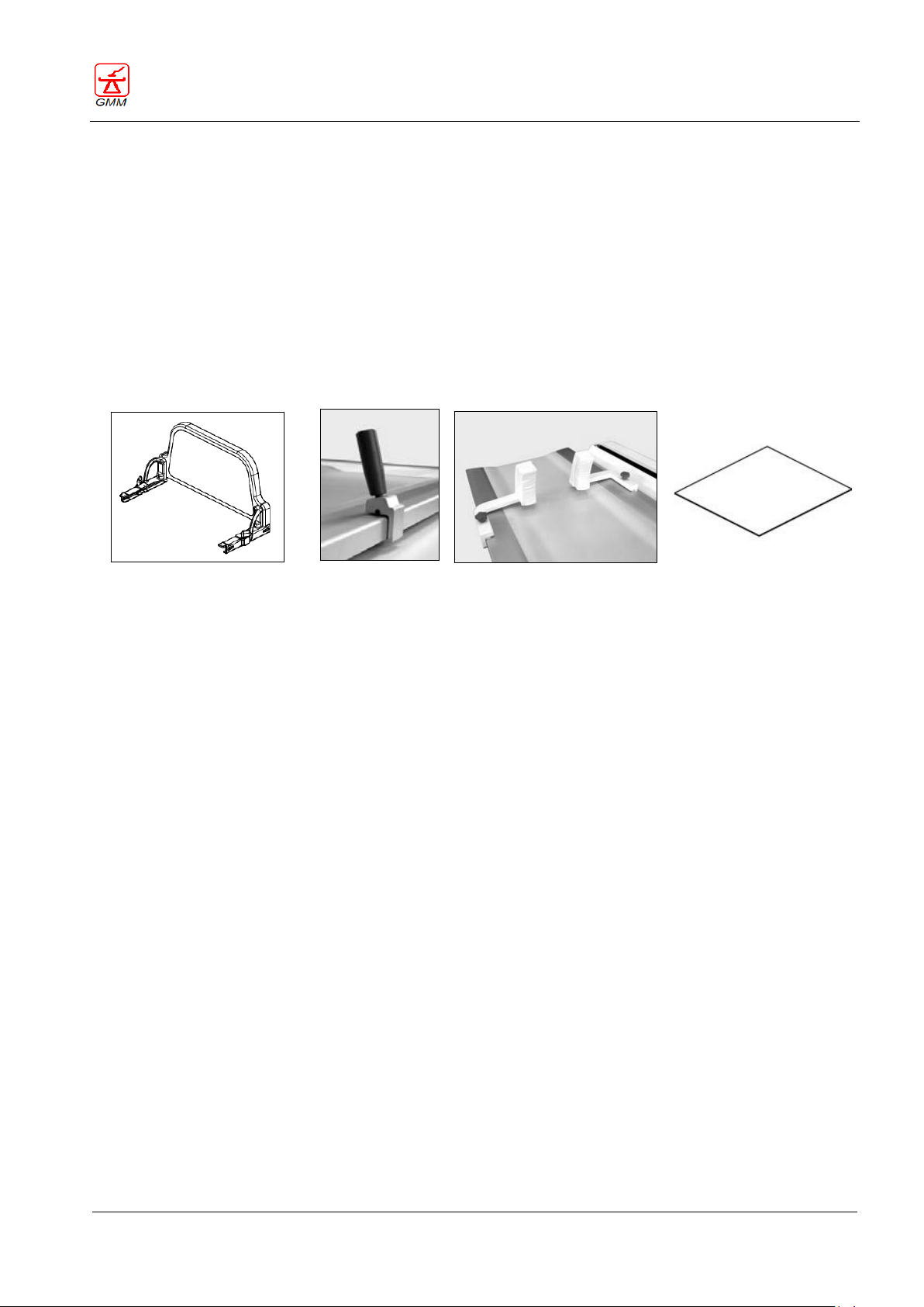
OPERATOR'S MANUAL OPERA T
August 2020
Page 87/135
Patient footrest
Handgrips
Shoulder-rests
Grid
- Compression belt
- Ankle-support
- Lower limbs support
- Lateral cassette support
- Head-contention device
- Support for glass of barium
- Adapter for cassette 15x40
- Adapter for cassette 13x18
- Intercommunication system
- Photocell for low ceilings
- Camera for remote patient monitoring
- Secondary console (in room)
- Paediatric cradle
- Double R/F remote foot pedal
- On-board console joystick
- Rotating footrest
- Patient step
- Grid 440x480 110L” R12:1 F140
- Grid 440x480 110L” R12:1 F180
- Grid 440x480 150L” R13:1 F120
- Grid 438x460 215L” R12:1 F120
- Grid 438x460 215L” R12:1 F180
- Detection chamber46x46
- Spacers for detection chamber
- Cushion on the tabletop
- Compressor with interchangeable cones
- Stitching bar
GENERAL MEDICAL MERATE S.P.A. CODE 62235 - REVISION 13
14. ACCESSORIES
The utmost suppleness of application and universality of the table are further enhanced by the availability of a
wide range of accessories.
Note: The accessories used must be the original ones.
14.1. Standard accessories
- Patient footrest 15 kg weight
- Handgrips 0,5 kg weight
- Shoulder-rests 4 kg weight
- Grid 440x480 110L” R12:1 F120
14.2. Optional accessories
Page 92
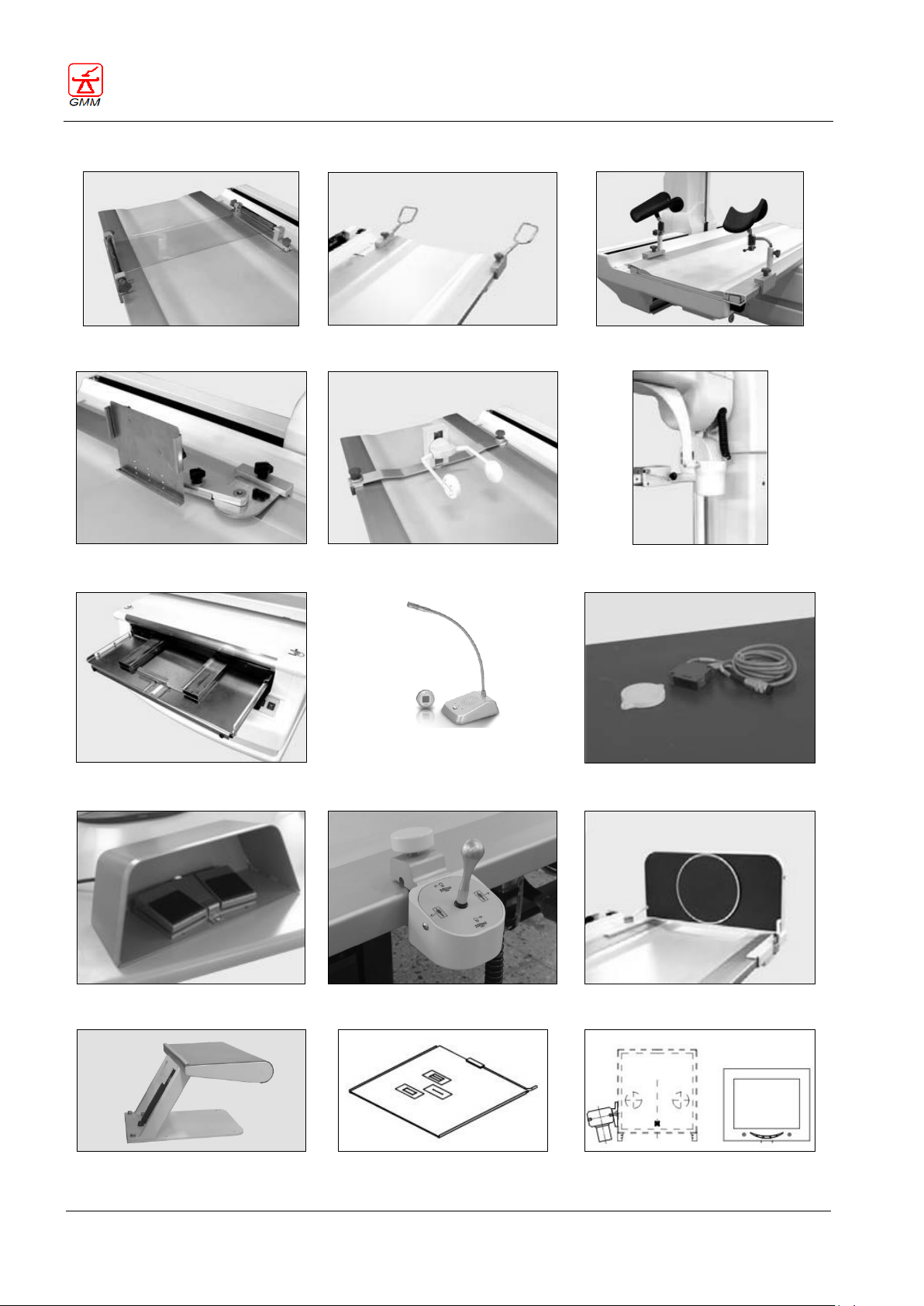
OPERATOR'S MANUAL OPERA T
August 2020
Page 88/135
Compression belt
Ankle-support
Lower limbs support
Lateral cassette support
Head-contention device
Support for glass of barium
13x18 and 15x40 cassette adapters
Intercommunication system
Photocell for low ceilings
Double R/F remote foot pedal
On-board console joystick
Rotating footrest
Patient step
Detection chamber
Camera for remote patient monitoring
GENERAL MEDICAL MERATE S.P.A. CODE 62235 - REVISION 13
Page 93
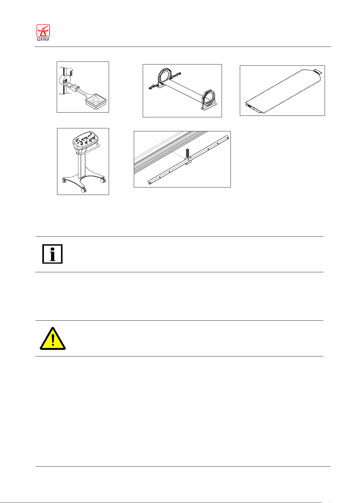
OPERATOR'S MANUAL OPERA T
August 2020
Page 89/135
Compressor with interchangeable
cones
Paediatric cradle
Cushion on the tabletop
Secondary console (in room))
Stitching bar
Please find in the next pages important information regarding use of the standard accessories
and use of a few optional accessories.
WARNING
Make sure all accessories are fitted correctly on their guides or support fixtures! If this is not
the case, they could fall and cause injuries to persons or damage to equipment during
machine tilting or movement phases.
GENERAL MEDICAL MERATE S.P.A. CODE 62235 - REVISION 13
14.3. Using the accessories
In order to ensure product safety, accessories exclusively made by the manufacturer or accessories made by
other suppliers but authorized by the manufacturer may only be used.
The user is held responsible for the use of other possible accessories that are not authorized by the
manufacturer.
Page 94
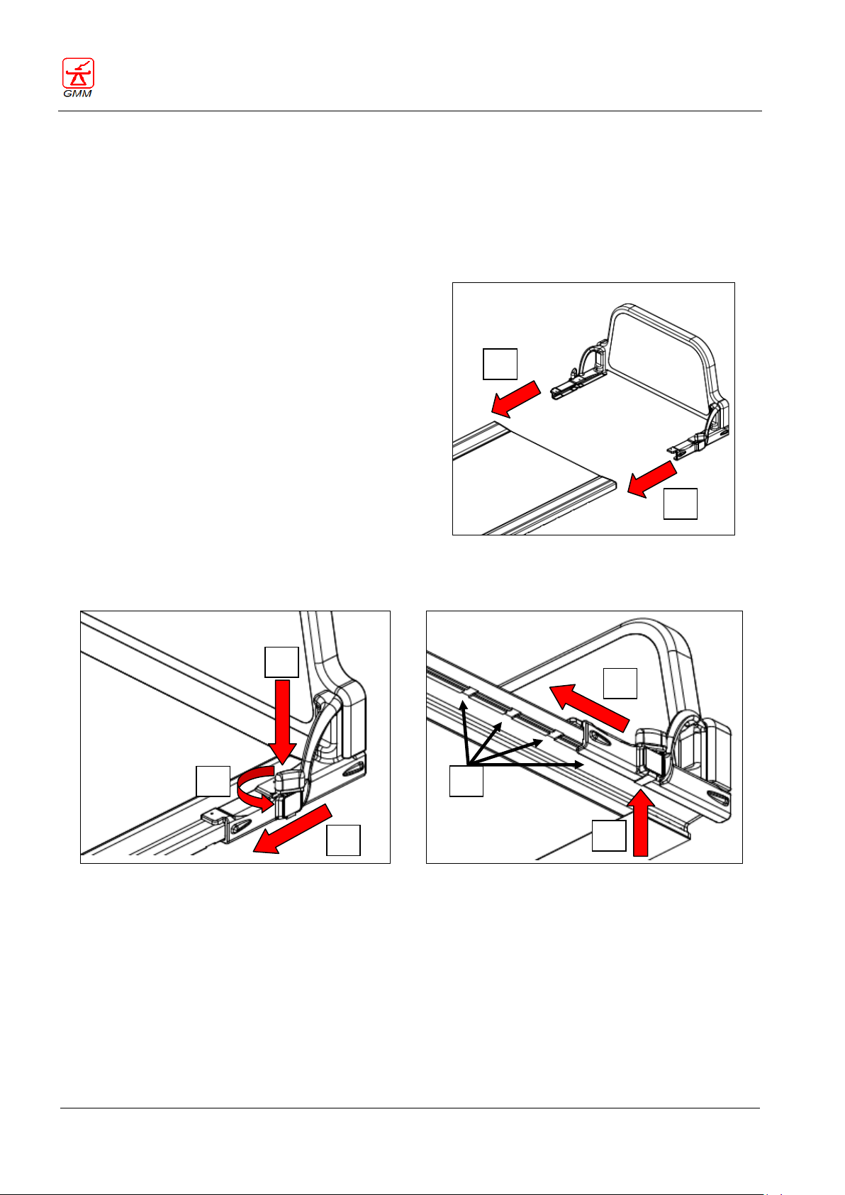
OPERATOR'S MANUAL OPERA T
August 2020
Page 90/135
To mount the footrest:
place the table in the horizontal position
hold the footrest so that its guides are perfectly
aligned with the guides of the tabletop
insert the footrest in the guides A-Fig. 6
rotate B-Fig. 7 and press both locking buttons on
the footrest C-Fig. 7
make the footrest slide by keeping the locking
buttons pressed until the footrest is almost
completely inserted in the guides A-Fig. 7
release the locking buttons and make the footrest
slide some cm more until you can hear the click of
the locking device of the footrest itself B-Fig. 8
Fig. 6 - Footrest mounting
make sure that the footrest is firmly secured to the guides by bearing down and pressing on the
longitudinal direction onwards and backwards.
Fig. 7 - Locking buttons
Fig. 8 - Locked position
A
A
A
B
C
A
B
C
GENERAL MEDICAL MERATE S.P.A. CODE 62235 - REVISION 13
14.3.1. Patient support footrest
When examinations are to be executed with the table in the vertical position, the patient-support footrest can
be used as a base support to keep the patient in the standing position or seated and can withstand patient
weights up to a maximum of 265 kg.
The footrest can be mounted either on the right end (normally the foot-side) or the left end (normally the
head-side) of the tabletop.
The footrest can also be fastened in a more advanced position compared with the center of the tabletop.
Normally this position is used when the operator wishes to seat the patient on the footrest (seat mode).
To mount the footrest in seat mode:
press the locking buttons so as to release the locking device
push the footrest some centimetres onwards and release the blocking buttons A-Fig. 8
keep on pushing the footrest slowly onwards until the new blocking position is reached C-Fig. 8
make sure that the footrest is firmly secured to the guides by bearing down on the longitudinal axis
onwards and backwards
Page 95
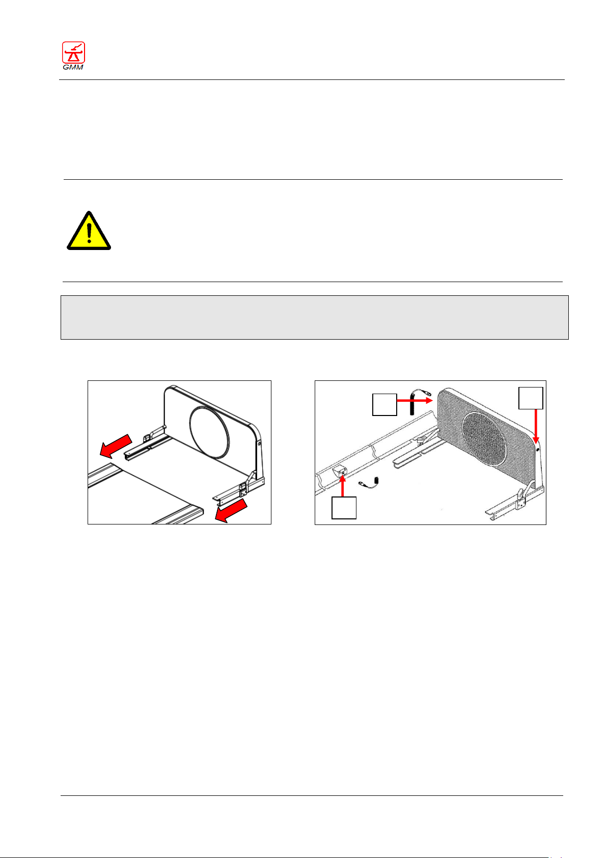
OPERATOR'S MANUAL OPERA T
August 2020
Page 91/135
WARNING
Make sure the footrest is correctly assembled on its support fixtures! If this is not the case,
they could come loose and cause injuries to persons and objects during machine tilting or
movement phases.
Do not execute any adjustment of the footrest when the table is in the vertical position: you
would take the risk to make the patient fall or hurt your feet.
Fig. 9 – Rotating footrest
Fig. 10 – Cable connection
A C B
GENERAL MEDICAL MERATE S.P.A. CODE 62235 - REVISION 13
To remove the footrest:
press the locking buttons so as to release the locking device
pull the footrest to draw it out from the guides (in the opposite direction compared to the center of the
table) by keeping the blocking buttons pressed at least until they are beyond the external edge of the
tabletop guides.
Mounting of the rotating footrest is done in the same manner as for standard footrest.
To mount the rotating footrest onto the tabletop, follow instructions provided in this section.
(150kg is the maximum patient weight allowed on the rotating footrest).
Upon fixing the footrest to the tabletop guides, connect the cable.
If the footrest is mounted on the foot side, the cable must be connected to point A-Fig. 10. If the footrest
is mounted on the head side, the cable must be connected to point B-Fig. 10.
Connect the second end of the cable to point C-Fig. 10, with the equipment switched off.
Switch the equipment on.
To remove the footrest:
Switch the equipment off.
Disconnect the cable from point C-Fig. 10.
Remove the footrest from the table
Switch the equipment on.
Page 96
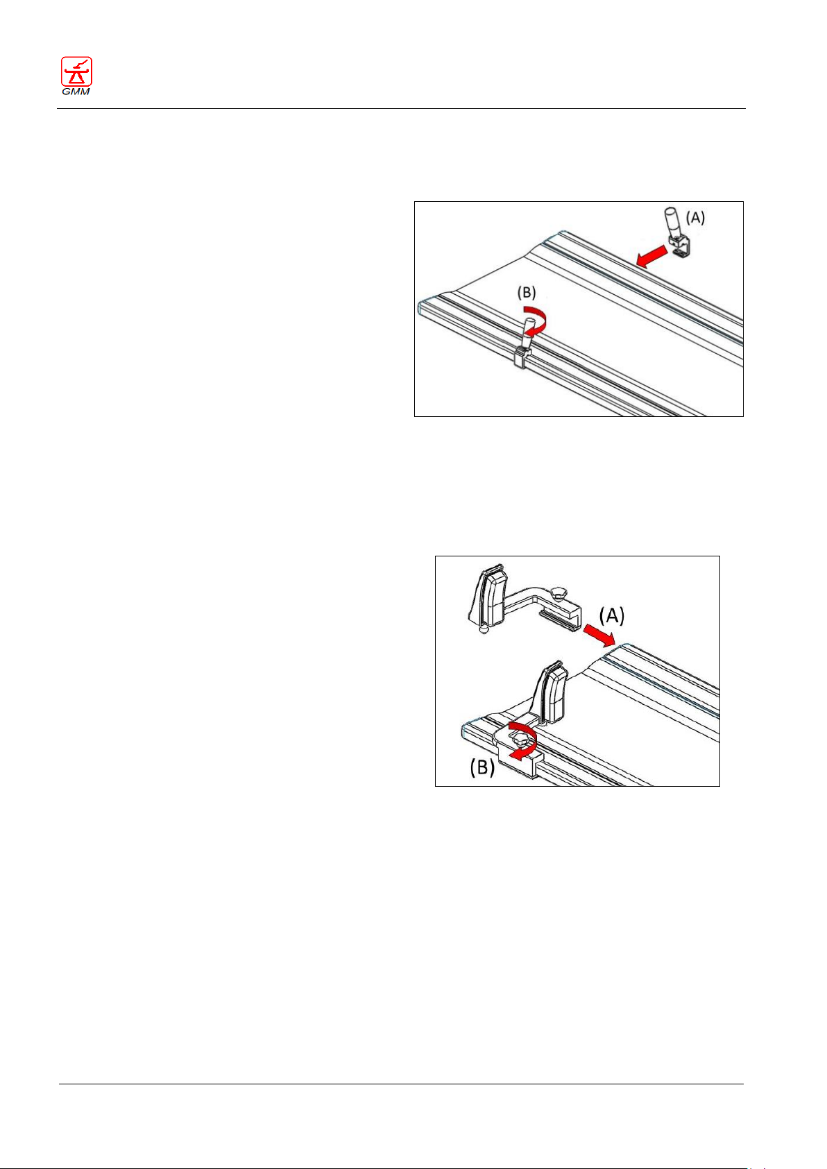
OPERATOR'S MANUAL OPERA T
August 2020
Page 92/135
To mount the handgrips:
place the table in the horizontal position;
loosen the knob of the handgrip as much as it
is necessary, by turning it counter clockwise;
insert the handgrip support on the tabletop
guide in the desired position A-Fig. 11;
fix the handgrip by turning the knob
thoroughly clockwise as shown in B-Fig. 11.
Fig. 11 - Handgrips mounting
To mount the shoulder-rests:
place the table in the horizontal position;
loosen the blocking knobs of the shoulder-rest
and insert it on the guide of the tabletop A-Fig.
12;
place the shoulder-rest in the wanted position
and fix it by turning the blocking knob clockwise
B-Fig. 12.
Repeat the same procedure to mount the second
shoulder-rest.
Fig. 12 - Shoulder-rest mounting
GENERAL MEDICAL MERATE S.P.A. CODE 62235 - REVISION 13
14.3.2. Handgrips
The handgrips ensure the patient a safe and firm holding position as well as an increased sensation of safety.
The handgrips can be fixed in any position of the tabletop guides.
14.3.3. Shoulder-rests
The shoulder-rests ensure complete safety to the patient when, during the examination, it is necessary to
place him in the trendelenburg position (e.g. myelography).
Since it is possible to use the shoulder-rests together with the handgrips, before mounting the shoulder-rests
it will be necessary to fix the hadgrips (if they are not already mounted on the guides):
Page 97
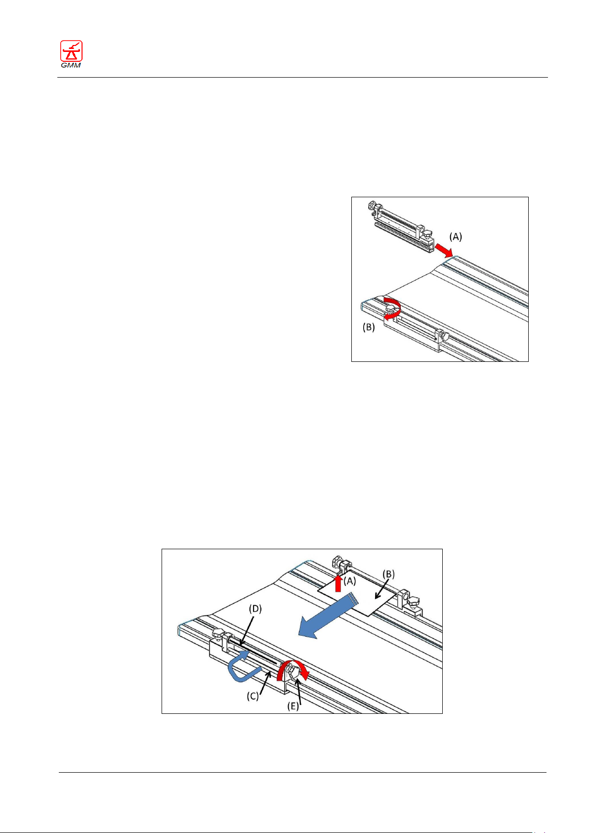
OPERATOR'S MANUAL OPERA T
August 2020
Page 93/135
To mount the supports:
• position the table in the horizontal position;
• insert one of the two mechanical supports in the
guides of the tabletop A-Fig. 13 and turn the locking
knob B-Fig. 13 clockwise in order to fix the support
onto the guide in the requested position;
• insert the other mechanical support in the opposite
guide symmetrically to the first, using the same
precautions and locking it in the desired position.
Fig. 13 - Assembling the belt supports
Fig. 14 - Assembling the compression belt
GENERAL MEDICAL MERATE S.P.A. CODE 62235 - REVISION 13
14.3.4. Compression belt
This accessory is normally used for compressing possible layers of tissue during the execution of abdominal
examinations in order to reduce the volume of the irradiated masses and thus reducing the quantity of
radiation scattering. This accessory consists of two mechanical supports for tension of a belt which is normally
wound around one of the two supports and can be removed to be periodically washed and sterilized.
By means of knobs it is possible to dose the compression belt’s tension.
To apply the belt:
raise the lever A-Fig. 14 of the support containing the compression belt B-Fig. 14 so that it is free to
unwind;
make the free end of the belt, inside which has been previously inserted a special rigid rod, pass under
the bar of the opposite belt C-Fig. 14;
insert the same end of the belt with the rigid rod inside the cleft of the take-up roller D-Fig. 14;
turn the knob of the take-up roller at least one turn clockwise E-Fig. 14;
lower the lever of the mechanical support A-Fig. 14 from which the belt was unwound so as to stop its
unwinding.
in order to properly extend the belt, turn clockwise the knob of the belt placed towards the free
external side of the tabletop E-Fig. 14.
Page 98
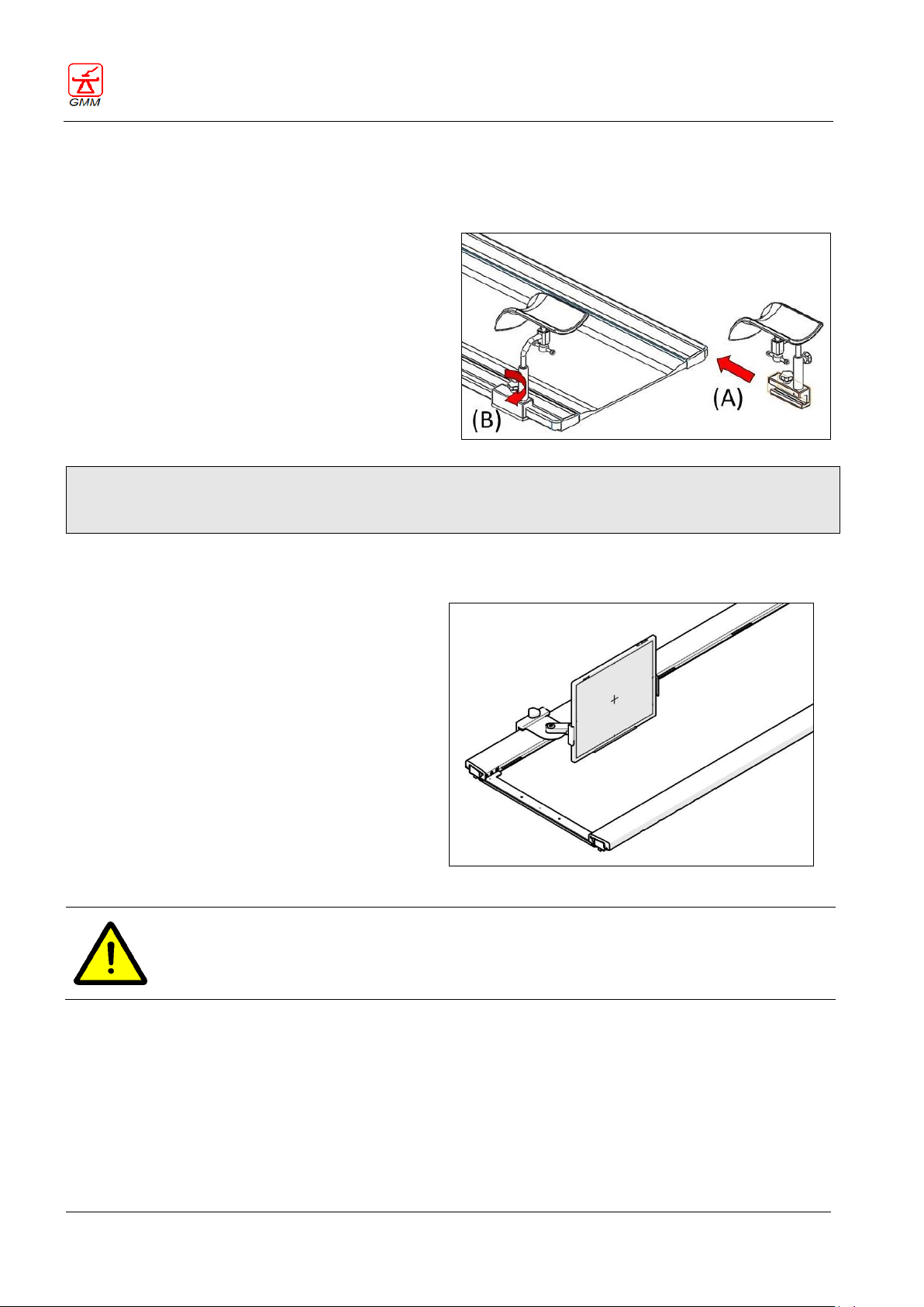
OPERATOR'S MANUAL OPERA T
August 2020
Page 94/135
To mount the lower limbs support:
place the tabletop in the horizontal position;
loosen the blocking knob of the first element
and insert it onto the tabletop guide as shown
in A-Fig. 15;
tighten the knob B-Fig. 15 checking that the
accessory is firmly fastened to the tabletop.
Repeat this sequence to assemble the second
element.
Fig. 15 - Mounting the lower limbs support
Mounting of the cassette/wifi detector support is
done in the same manner as for the leg support.
To mount the cassette/wifi detector support onto
the tabletop, follow the instructions provided in
the leg support section.
Attention
Always place the tabletop in the horizontal
position first.
Cassette / wifi detector support
WARNING
Both the mounting and the use of the support for cassette / wifi detector are allowed only with
the table in the horizontal position.
In no case is the operator allowed to use this accessory with the table in vertical position!
GENERAL MEDICAL MERATE S.P.A. CODE 62235 - REVISION 13
14.3.5. Lower limbs support
The lower limbs support device consists of two separate elements.
The correct assembly position for the accessory on the tabletop guides can be seen in Fig. 15.
Mounting of Ankle-support, Lateral cassette support and Head-contention device are done in the same
manner as for the Lower limbs support. To mount the four above mentioned accessories onto the tabletop,
follow instructions provided in the present section.
14.3.6. Lateral support for cassette / wifi detector (without grid)
Page 99
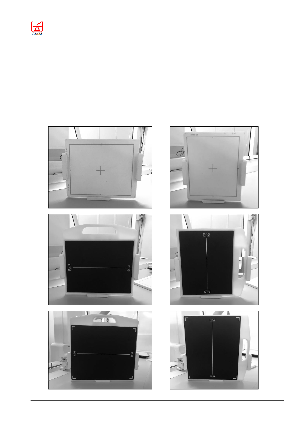
OPERATOR'S MANUAL OPERA T
August 2020
Page 95/135
GENERAL MEDICAL MERATE S.P.A. CODE 62235 - REVISION 13
14.3.7. Lateral support for wireless detector /CR cassette
The lateral support for wireless/CR cassette is an optional accessory, used to position the following imagereceptors on the table-top:
- Wireless detector/ CR cassette without detector case
- Wireless detector/ CR cassette with detector case, without anti-scatter grid
- Wireless detector/ CR cassette with detector case and anti-scatter grid
The image-receptors, available in various formats, can be used both vertically and horizontally
(portrait/landscape). The anti-scatter grid is available in two versions: with or without handle.
Below are shown, by way of example, some types of image receptors that can be used with this accessory.
Page 100
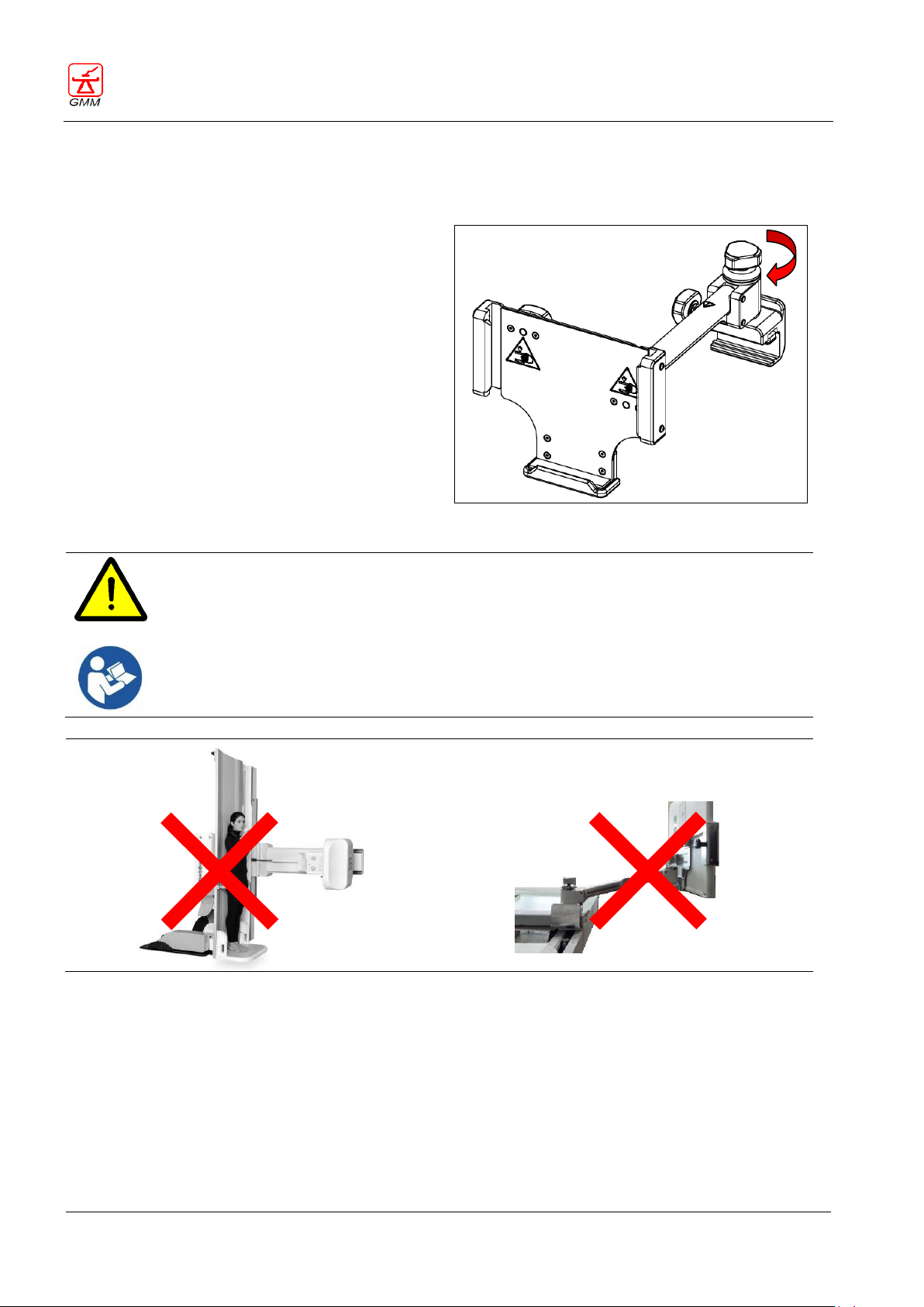
OPERATOR'S MANUAL OPERA T
August 2020
Page 96/135
Mounting the support:
Move the tabletop in a horizontal position
loosen the locking knob (A) of the support
and insert it on the top guide in the
required position
Screw the knob (A) back on, making sure that
the accessory is securely fastened to the
examination table.
Lateral support for wireless detector
WARNING
Both mounting and use of the lateral support for wireless detector is only permitted with the
table in a horizontal position and the accessory positioned on the patient table top.
Under no circumstances may the user use this accessory with the table in a vertical or
tilted position outside the patient tabletop!
(A)
GENERAL MEDICAL MERATE S.P.A. CODE 62235 - REVISION 13
The lateral support for wireless detector/CR cassette can be mounted anywhere on the side rails of the
patient tabletop, on both sides of the table.
 Loading...