

Page 1
INSTRUCTION MANUAL
GX850 INSTRUCTION MANUAL 1
Page 2

CONTENTS
INTRODUCTION .................................................................3
CAUTION ........................................................................... 3
RF RADIATION INFORMATION ............................................ 3
OPERATING RULES ............................................................. 4
Radio Licences .................................................................4
RANGE .............................................................................. 4
MARINE MOBILE SERVICE IDENTITY (MMSI) ....................... 5
FEATURES .......................................................................... 5
SUPPLIED WITH .................................................................. 5
OPTIONAL ACCESSORIES .................................................... 5
CONTROLS ......................................................................... 6
LCD Icons ........................................................................... 7
KEY FUNCTIONS ................................................................ 7
GENERAL OPERATION ........................................................ 8
Power On/Off Volume Control........................................... 8
Squelch ............................................................................ 8
Channel Selection ............................................................8
Weather Channels............................................................ 8
16 Key ............................................................................. 8
Second Priority Channel ................................................... 9
Hi/Lo Power ..................................................................... 9
Key Lock ..........................................................................9
Scrambler......................................................................... 9
Man Over Board (MOB) .................................................... 9
Backlight ......................................................................... 9
Scanning .......................................................................... 9
Dual Watch .................................................................... 10
Triple Watch ................................................................... 10
Time Out Timer ............................................................... 11
Displaying Time and Date ............................................... 11
Displaying Local Time ..................................................... 11
Digital Selective Calling .................................................. 11
DSC and GPS ................................................................. 11
User MMSI ..................................................................... 11
Distress Calls ................................................................. 11
DSC MENU ...................................................................... 12
My MMSI ID Setup ......................................................... 13
Individual Call, Position Request, Group Call and Test Call 13
All Ships Call .................................................................. 15
Receive Call Log ............................................................. 16
Send Call Log ................................................................. 16
Phone Book ................................................................... 17
DSC Setup ..................................................................... 18
MAIN MENU OPTIONS ..................................................... 18
VHF Operation ............................................................... 19
GPS Setup ...................................................................... 19
ATIS Operation ............................................................... 19
My ATIS ID ..................................................................... 20
DSC Operation ............................................................... 21
My MMSI ID ................................................................... 21
D Backlight ................................................................21
LC
Backlight Time ............................................................... 21
LCD Contrast .................................................................21
Key Beep........................................................................ 21
Version Info ................................................................... 22
Factory Reset ................................................................. 22
Charging the Battery ...................................................... 22
INTERNATIONAL MARINE VHF CHANNEL
AND FREQUENCIES .......................................................... 23
U.S. MARINE VHF CHANNEL FREQUENCIES ...................... 25
CANADIAN MARINE VHF CHANNEL AND FREQUENCIES ... 28
SPECIFICATIONS ..............................................................33
SC CONTRACT WARRANTY AGAINST DEFECTS ................. 34
2 INSTRUCTION MANUAL GX850
Page 3

INTRODUCTION
Congratulations on purchasing this GME fully featured VHF
marine radio. Your GX850 has been built to offer excellent
value by combining advanced features, great design and
manufacturing quality. To ensure you are familiar with the
operation and features of your radio, and in order to obtain
the best performance, please read this manual thoroughly
before operation.
CAUTION
IMPORTANT: READ ALL INSTRUCTIONS carefully and
completely before operating your radio and retain this
manual for future reference.
To maintain the waterproof integrity of the radio;
• ENSURE the antenna and the connector cover are
both firmly tightened against the rubber seal (refer
diagram on page 6).
• NEVER attempt to disassemble the radio.
NEVER: connect the radio to a power source other than
the supplied battery. This may damage your product.
NEVER: operate your radio with the antenna less than
5 cm from exposed parts of the body.
NEVER: use or charge your radio in a potentially
explosive atmosphere.
DO NOT: use your radio with a damaged antenna.
DO NOT: attempt to modify your radio in any way.
ALWAYS: charge your radio at normal room temperature.
ALWAYS: switch off your radio where notices restrict the
use of two-way radio or mobile telephones.
AVOID: storing or charging your radio in direct sunlight.
AVOID: storing or using your radio where temperatures
are below -20º C or above +60º C.
RF RADIATION INFORMATION
RF RADIATION PROFILE
Your radio is designed and tested to comply with a number
of national and international standards and guidelines
GX850 INSTRUCTION MANUAL 3
(listed below) regarding human exposure to radio frequency
electromagnetic energy. This radio complies with the IEEE
and ICNIRP exposure limits for occupational/controlled RF
exposure environment at operating duty factors of up to 50%
transmitting and is authorised by the FCC for occupational
use only. In terms of measuring RF energy for compliance
with the FCC exposure guidelines, your radio radiates
measurable RF energy only while it is transmitting (during
talking in PTT mode), not when it is receiving (listening) or in
standby mode.
The device complies with SAR and/or RF field strength limits
of RSS-102 requirements.
RF RADIATION SAFETY
In order to ensure user health, experts from relevant
industries including science, engineering, medicine and health
work with international organizations to develop standards
for safe exposure to RF radiation. These standards consist of:
• United States Federal Communications Commission,
Code of Federal Regulations; 47CFR part 2 sub-part J;
• American National Standards Institute (ANSI)/Institute of
Electrical and Electronic Engineers (IEEE) C95. 1-1992;
• Institute of Electrical and Electronic Engineers (IEEE) C95.
1-1999;
• International Commission on Non-Ionizing Radiation
Protection (ICNIRP) 1998;
FCC Regulations
Federal Communication Commission (FCC) requires that all
radio communication products should meet the requirements
set forth in the above standards before they can be marketed
in the U.S, and the manufacturer shall post a RF label on the
product to inform users of operational instructions, so as to
enhance their occupational health against exposure to RF energy.
Part 15 Compliance
This equipment has been tested and found to comply with
the limits for a Class B digital device, pursuant to part
15 of the FCC Rules. These limits are designed to provide
reasonable protection against harmful interference in a
residential installation. This equipment generates, uses and
can radiate radio frequency energy and, if not installed and
Page 4
used in accordance with the instructions, may cause harmful
interference to radio communications. However, there is no
guarantee that interference will not occur in a particular
installation. If this equipment does cause harmful interference
to radio or television reception, which can be determined by
turning the equipment off and on, the user is encouraged to
try to correct the interference by one or more of the following
measures:
• Reorient or relocate the receiving antenna.
• Increase the separation between the equipment and
receiver.
• Connect the equipment into an outlet on a circuit different
from that to which the receiver is connected.
• Consult your dealer or an experienced radio/TV technician
for help.
NOTE: Changes or modifications to this unit not expressly
approved by the party responsible for compliance could void
the user’s authority to operate the equipment.
EU Regulatory Conformance
As certified by the qualified laboratory, the product is in
compliance with the essential requirements and other
relevant provisions of the Directive 1999/5/EC. Please note
that the above information is applicable to EU countries only.
RADIO LICENCES
Ship Station License
When your craft is equipped with a VHF FM radio, you must
have a current radio station licence before using the radio.
It is unlawful to operate a ship station which is not licensed.
Inquire through your dealer or the appropriate government
agency for a Ship-Radiotelephone license. This license
includes the call sign which is your craft’s identification for
radio purposes.
Operators License
A restricted Radiotelephone Operator Permit is the license
most often held by small vessel radio operators when a
radio is not required for safety purposes. The restricted
Radiotelephone Operator Permit must be posted near the
radio or be kept with the operator.
Only a licensed radio operator may operate a radio. However,
non-licensed individuals may talk over a radio if a licensed
operator starts, supervises, ends the call and makes the
necessary log entries.
A current copy of the applicable government rules and
regulations is only required to be on hand for vessels in which
a radio telephone is compulsory. However, even if you are
not required to have these on hand it is your responsibility
to be thoroughly acquainted with all pertinent rules and
regulations.
OPERATING RULES
Priorities
• Read all rules and regulations pertaining to priorities and
keep an up-to-date copy handy. Safety and distress calls
take priority over all others.
• You must monitor Channel 16 when you are not operating
on another channel.
• False or fraudulent distress calls are prohibited under law.
Privacy
• Information overheard but not intended for you cannot
lawfully be used in any way.
• Indecent or profane language is prohibited.
4 INSTRUCTION MANUAL GX850
The range of VHF transmissions depends on antenna height,
transmitter power and the terrain over which the signals
pass. For a 5 watt handheld radio like the TX850, ship to
ship communications up to 5 nautical miles should be
possible. Using an external antenna should allow ship to ship
communication of 8 nautical miles or more. Ship to shore
ranges will often be greater due to the increased height of
the shore antenna.
RANGE
Page 5

MARINE MOBILE SERVICE IDENTITY
(MMSI)
The MMSI is a 9-digit number used to identify a radio that is
capable of using Digital Selective Calling (DSC). The number
is used to selectively call other vessels. To setup and use the
DSC feature on your radio: Please refer to the ‘DSC’ section of
this manual.
USER MMSI
To use the DSC feature you must be registered with the
appropriate licensing authority (AMSA in Australia) who
will issue you with your unique user MMSI number. Having
a registered user MMSI means you can be identified much
quicker in an emergency. Once you have obtained your MMSI
number you can then enter this into your GX850 to enable
DSC operation. Your GX850 is shipped from the factory
without a user MMSI number. It is up to the user to obtain a
valid MMSI from the appropriate licensing authority.
NOTE: If you don’t register for a User MMSI, you can still
receive DSC distress calls from other vessels however you
cannot send a DSC call.
GROUP MMSI
The Group MMSI is used for DSC Group Calls. A Group Call
provides a method for contacting a group of vessels with a
common interest, for example, alerting all yachts in a race to
announce a change in the race conditions. Any number with
a leading zero can be used as a Group MMSI, and they do
not need to be registered, but the entity deciding on a Group
MMSI must use the MID of the host country or country of
vessel registration (e.g. 503 in Australia). The Group ID should
be based on a key vessel in the Group, and the recommended
system is to drop the last digit of the key vessel’s MMSI and
place a zero in front.
For example, a fleet of vessels that has a lead vessel with a
DSC User MMSI of 503080110 could use the Group MMSI
of 050308011. This would then be programmed into all fleet
vessels as the special event Group MMSI.
See ‘My MMSI ID Setup’ on page 13 for details on entering
a group MMSI.
FEATURES
• Waterproof to IP67
• Man Overboard Alarm Function
• Floats with Auto-Flashing LCD if dropped overboard
• Integrated 48 Channel GPS Receiver
• 5/1 watt Switchable Power
• Large Dot-Matrix LCD
• Private Channel Facility
• Programmable Scan, Priority Scan, Dual and Tri Watch
• All International, US and Canadian Marine VHF
Channel Sets.
• Integrated 1700 mAh Lithium Polymer Battery
SUPPLIED W ITH
• GX850 DSC Marine Radio
• Belt Clip
• 240V AC Charger
• Wrist Strap
• High Gain Flexible Antenna
• Instruction Manual
OPTIONAL ACCESSORIES
• MB046 – Belt Clip
• PSK20P – Plug Pack for 9V1A Prop Conn
• AE4024 – Flexible Antenna
• CSGX850 – Cap and Seal
GX850 INSTRUCTION MANUAL 5
Page 6
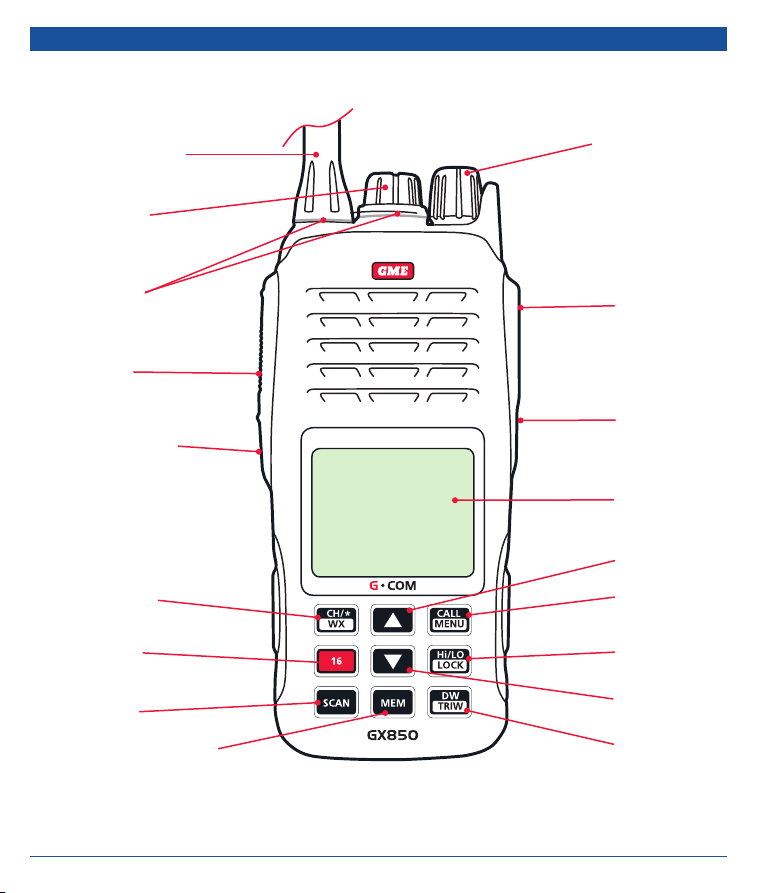
CONTROLS
ANTENNA
CONNECTOR
COVER
RUBBER
SEAL
PTT
SCRM/ MOB
CH / WX
CH 16
SCAN
VOLUME
ON/ OFF
DISTRESS
SQL
DISPLAY
UP
CALL / MENU
HI / LO POWER
KEY LOCK
DOWN
MEMORY
6 INSTRUCTION MANUAL GX850
DUAL WATCH /
TRIPLE WATCH
Page 7
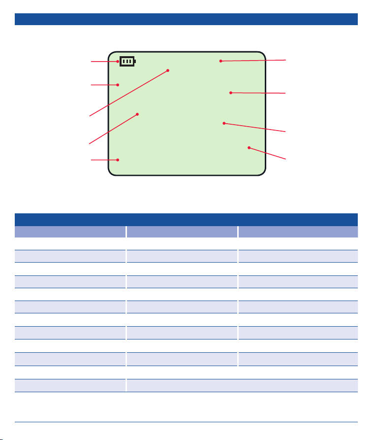
LCD ICONS
BATTERY LEVEL
HIGH TX
POWER
DIGITAL SELECTIVE
CALLING
SQUELCH LEVEL
DATE/ TIME
KEY SHORT PRESS LONG PRESS
Hi/LO [LOCK] Transmit Power Hi/Low Key Lock / Key Unlock
16 CH 16 Secondary Priority channel
DW [TRIW] Dual Watch Mode Triple Watch mode
CH/* [WX] Private Channel Weather channel
SCAN Scan Priority Scan
MEM Memory Mode Save/Delete Memory channel
Up/ Down Channel Up/Down Fast Up/Down
Call/ Menu DSC Menu Main Menu
SCRM/MOB Scrambler MOB Activated
Distress Distress Menu Distress Alert Calling
SQL Squelch Setting Switch ON/OFF Time and Date Display
Volume Knob Power ON / OFF. Adjust the Volume Level
HI
SQL :5
24 OCT 03 : 39 UTC
DSC
DISTRESS
22° 32. 3608’ S
113° 57. 0323’ E
KEY FUNCTIONS
INT
16
BAND
CHANNEL
DISTRESS MODE
GPS POSITION
GX850 INSTRUCTION MANUAL 7
Page 8
GENERAL OPERATION
POWER ON/OFF VOLUME CONTROL
Turn the Volume knob clockwise past the ‘click’ to turn the
radio ON. Continue turning the knob clockwise to increase
the volume. Turn the knob counter-clockwise to reduce the
volume. Continue turning the knob counter clockwise past
the ‘click’ to turn the radio OFF.
SQUELCH
To adjust the Squelch, briefly press the SQL key. The present
squelch level will be displayed. Use the
to adjust the squelch level from 0 (min) to 9 (max).
or keys
CHANNEL SELECTION
Briefly press the key to step upwards one channel or the
key to step downwards one channel. Press and hold the
or keys to scroll quickly through the channels at a
faster rate. When the key is released the channel scrolling stops.
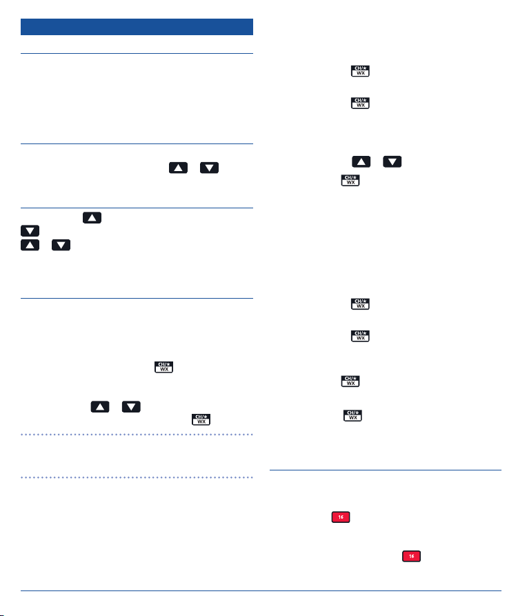
WEATHER CHANNELS (USA & CANADIAN
CHANNEL SET)
The US NOAA weather channels are available only when the
USA or Canadian Channel Set is selected. Weather channels
are not available on the International marine band.
To access the weather channels while on the USA or
Canadian band, press and hold the
will switch to the weather channels and the ‘WX’ icon will
appear. Weather channels are numbered 01 – 10 and are
selected using the
communications channels press and hold the
NOTE: Weather channels provide a receive-only weather
information service in and around the USA and Canada. You
cannot transmit on the weather channels.
Weather Alert Operation (WAT) (USA & Canada)
When a weather warning is issued in your area the NOAA
weather service will transmit a weather alert tone on your
local weather channel. If the weather alert function is
activated on your radio, the reception of this tone will cause
a short alarm to sound and the radio will automatically tune
to the weather channel where the alert tone was detected.
8 INSTRUCTION MANUAL GX850
or keys. To return to the normal
key. The radio
key again.
The alert should be detected in all the modes of operation
including Standby, Dual and Tri-watch and Scan etc.
To Activate the Weather Alert Function
1. Press and hold the
channels. ‘WX’ is displayed.
2. Press and hold the
weather alert function. ‘WAT’ will appear in the upper right
of the display.
3. Select the local weather channel that you wish to monitor
for alerts using the
4. Briefly press the
When the weather alert function is enabled the radio will
check the selected weather channel every 4 seconds for a
weather alert tone. If an alert tone is detected, the ‘WX’ and
‘WAT’ icons will flash and a short alarm tone will sound. The
radio will then automatically switch to the selected weather
channel to allow you to hear the weather warning.
To disable weather alerts;
1. Press and hold the
channels. ‘WX’ is displayed.
2. Press and hold the
weather alert function. ‘WAT’ will disappear from the
upper right of the display.
3. Briefly press the
Private Channels
A brief press of the
feature is not available to users in Australia and New
Zealand.
key to select the weather
key again to switch ON the
or keys.
key to return to normal operation.
key to enable the weather
key again to switch OFF the
key to return to normal operation.
key is for private channels. This
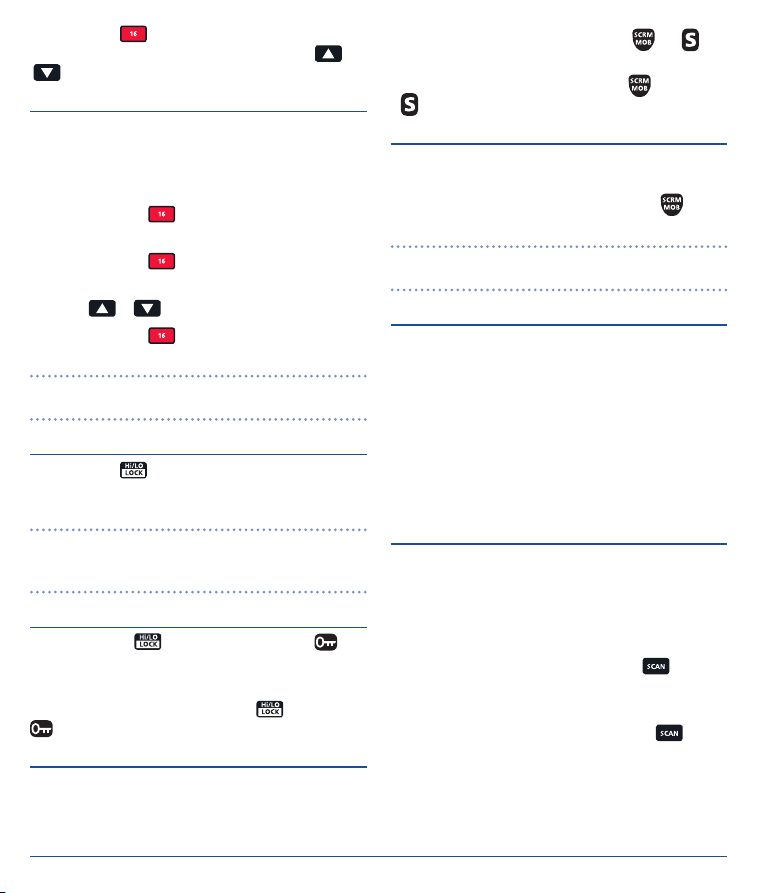
16 KEY
The GX850 supports two priority channels.
Priority Channel 16
Briefly press the
previous functions such as scanning or low power will be
cancelled and the radio will switch to channel 16 with Hi
transmit power selected. When the
channel 16, ‘P-CH’ is displayed.
key to switch to Channel 16. All
key is used to select
Page 9
Briefly press the key again to return to the last selected
channel or to go to an alternative channel press the
keys.
SECOND PRIORITY CHANNEL
Programming the Second Priority Channel
The second priority channel can be preset through the main
menu (see menu section) or can be changed directly from the
display as follows.
1. Press and hold the
Priority channel. ‘P-2nd’ is displayed.
2. Press and hold the
displayed and the channel number flashes.
3. Use the
4. Press and hold the
the second priority channel.
NOTE: Priority channel 16 is factory set and cannot be
changed.
key to switch to the second
key again. ‘Set 2nd Prior CH’ is
or keys to select a new channel.
key to store the new channel as
HI/LO POWER
Briefly press the key to toggle high or low transmitter
power. The display will show ‘Hi’ or ‘Lo’ to confirm the
selected power setting.
NOTE: Some channels may be permanently set to Hi or Lo
power by default. If any of these channels are selected you
will not be able to change the power setting for that channel.
KEY LOCK
Press and hold the key to lock the keypad. The
icon will be displayed when the keypad is locked and all keys
except the PTT and any Distress related keys will be locked.
To unlock the keypad, press and hold the
icon will disappear.
key again. The
SCRAMBLER
Your radio incorporates a simple voice scrambler that, when
activated, will make your signal intelligible only to other
radios using the same scrambler technology.
GX850 INSTRUCTION MANUAL 9
• To activate the Scrambler, briefly press the key. will
or
appear on the display.
• To disable the Scrambler, briefly press the
will disappear from the display.
MAN OVER BOARD (MOB)
The MOB function is designed to automatically send a MOB
distress call with your MMSI and latitude and longitude.
To activate the MOB function, press and hold the
2 seconds.
NOTE: In order to make DSC distress calls including MOB calls
you must have your user MMSI programmed into your radio.
BACKLIGHT
The backlight operates automatically whenever any key
(except the PTT) is pressed and switches off about 7 seconds
after the last keypress. The backlight provides lighting for the
display, keypad and Distress button.
Water Activated Backlight Alert
If the GX850 is immersed in water, sensors built into the
case will cause the backlight to flash urgently. This feature is
designed to make it easier to locate and recover your radio if
it is accidentally dropped into water.
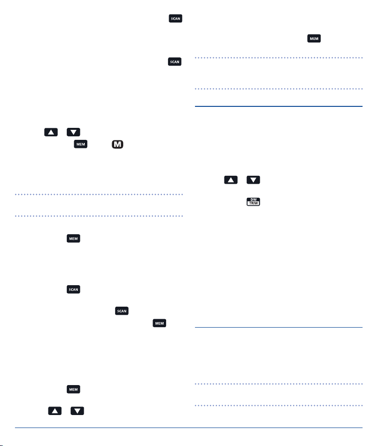
SCANNING
Basic Scan
The basic scan function allows the radio to scan all channels
for transmissions. When a signal is detected the scan pauses
to allow the signal to be heard. Once the signal has gone the
scan resumes.
To activate the scan function, briefly press the
‘SCAN’ appears on the display and the channel numbers
change rapidly.
To deactivate the scan function, briefly press the
again. ‘SCAN’ disappears from the display.
Priority Scan
Priority scan is similar to the basic scan except it regularly
inserts channel 16 into the scan. Signals received on channel
16 have priority over signals received on other channels.
key again.
key for
key.
key
Page 10
To activate the Priority scan function, press and hold the
key. ‘SCAN’ appears on the display and the channel numbers
change rapidly with channel 16 appearing predominantly in
the channel display area.
To deactivate the Priority scan function, briefly press the
key. ‘SCAN’ disappears from the display.
User Memory Scan
User Memory Scan allows you to program a select group of
channels for scanning.
To Program User Memory Channels
1. Use the
2. Press and hold the
the right of the selected channel number to confirm the
channel is in Memory.
3. Repeat steps 1 and 2 to add further channels to the User
Scan Memory.
NOTE: Separate User Memories can be stored for USA,
International and Canadian bands.
To Activate the User Memory Scan
1. Briefly press the
channel display indicating the radio is now in User Memory
mode and the channel number switches to a User Memory
channel (only User Memory channels are displayed while
in User mode).
2. Briefly press the
User Memory channels.
3. To stop scanning; briefly press the
4. To exit the User Channel mode, briefly press the
‘USER’ will disappear from the display and the radio will
return to the last selected channel.
Reviewing User Memory Scan Channels
To quickly determine which channels are stored in the User
Memory;
1. Briefly press the
Channel display.
2. Press the
or keys to select the required channel.
key. The icon appears to
key. ‘USER’ appears to the left of the
key. The radio will begin scanning the
key.
key.
key. ‘USER’ appears to the left of the
or keys to quickly to step through the
Memory Scan channels. Only channels stored in Memory
Scan will be displayed.
3. To exit Memory Scan, briefly press the
disappear from the display.
NOTE: You cannot add or remove channels from the User
Memory Scan while in the User mode. You must exit the User
mode to edit User Memory channels.
key. ‘User’ will
DUAL WATCH
The Dual Watch function is a 2 channel scan feature where
the radio switches between Channel 16 and any other
selected channel. This allows you to monitor a working
or club channel while still being able to receive important
broadcasts on Channel 16.
To use the Dual Watch function:
1. Use the
channel.
2. Briefly press the
‘DUALW’ will be displayed and the channel number will
quickly alternate between 16 and the selected channel as the
radio monitors both channels.
If a signal is received on the selected channel, the Dual Watch
will pause to allow the signal to be heard but will continue to
monitor channel 16 every 2 seconds resulting in short breaks
in the conversation. Once the signal has gone, Dual Watch
continues.
If a signal appears on channel 16 it will take priority over any
signals on the selected channel.
or keys to select your preferred working
key to activate Dual Watch.
TRIPLE WATCH
The Triple Watch function is a 3 channel scan feature where
the radio switches between Channel 16, a selected channel
and the second priority channel. This allows you to monitor
2 channels while still being able to receive important
broadcasts on Channel 16.
NOTE: Prior to using Triple Watch ensure you have
programmed your second priority channel.
10 INSTRUCTION MANUAL GX850
Page 11

To use the Triple Watch Function
1. Use the
channel.
2. Press and hold the
‘TRIW’ will be displayed and the channel number will
quickly switch between 16, the second priority channel and
the selected channel.
If a signal is received on the either selected channel or
the second priority channel, the Triple Watch will pause to
allow the signal to be heard but will continue to monitor
channel 16 every 2 seconds resulting in short breaks in
the conversation. Once the signal has gone, Triple Watch
continues.
If a signal appears on channel 16 it will take priority over any
signals on the other channels.
or keys to select your preferred working
key to activate Triple Watch.
TIME OUT TIMER
The radio has a built-in time out timer that automatically
limits transmissions to a maximum of 5 minutes of
continuous operation. This feature is required to prevent
accidental blocking of the frequency should your PTT become
jammed or be otherwise pressed accidentally.
When the time out timer activates, the transmission will stop,
and the radio will return to receive mode. Normal operation
will be restored once the PTT is released.
DISPLAYING TIME AND DATE
When the GX850 is not receiving GPS signals, the screen will
display the time and date.
To switch the time and date display on or off, press and hold
the SQL key for 3 seconds.
DISPLAYING LOCAL TIME
GPS time is received from the satellites in UTC format. To
display the time as local time please refer to the GPS Setup
option on page 19.
DIGITAL SELECTIVE CALLING
The Digital Selective Calling (DSC) feature on your GX850
uses preformatted digital data messages instead of voice to
transmit urgent or important information to another radio. In
GX850 INSTRUCTION MANUAL 11
times of an emergency, DSC can alert all radios within range
to a distress message even when a listening watch is not
being maintained. This increases the chances of your signal
being heard. DSC can also be used to make All Ships Calls,
Group Calls and Position Requests as well as routine calls to
individual radios.
DSC is part of the Global Maritime Distress and Safety System
(GMDSS) which is expected to eventually replace listening
watches on distress frequencies and will be used to announce
all routine and urgent maritime safety information broadcasts.
DSC AND GPS
DSC operation is enhanced by the in-built GPS receiver
in your GX850. By using GPS, your distress call can
automatically include your current position and time. If a
GPS position cannot be obtained, DSC calls can still be sent
and received to alert the operator of another vessel for
subsequent voice communication.
DSC calls are automatically sent and received on CH70. The
GX850 has two receivers, one of which is dedicated to CH70.
Therefore, regardless of which channel you are operating on,
the GX850 will not miss a DSC call.
USER MMSI (MARINE MOBILE SERVICE IDENTITY)
A User MMSI is a unique 9-digit number used to identify a
DSC capable radio. An MMSI is used to selectively call other
vessels. Before you can use DSC, you must enter your User
MMSI number into the ‘My MMSI ID’ option in the DSC
Menu. If you don’t yet have a User MMSI, please register
with your local Maritime Authority (AMSA in Australia - go
to http://www.amsa.gov.au/mmsi/ for more details and to
download an application form) who will then issue a unique
MMSI number. Please refer to the ‘My MMSI ID’ option
further below for instructions on entering your User MMSI.
DISTRESS CALLS
To make a Distress Call use the button under the Red
DISTRESS cover on the side of the GX850. To make any
other DSC call, use the
Making a Distress Call
1. Lift the bottom of the Red DISTRESS cover on the side of
the radio.
key on the main keypad.
Page 12

PRESS
LIFT
COVER
2. Briefly press the DISTRESS button. The display shows the
‘Distress’ Menu list.
Distress Menu
Undesignated
Fire, Explosion
Flooding
Collision
Grounding
Capsizing
Sinking
Exit
3. Use the or keys to select the nature of the
distress. The list includes: Undesignated, Fire,Explosion,
Flooding, Collision, Grounding, Capsizing, Sinking, Adrift,
Abandoning, Piracy and Man Overboard.
4. Press and HOLD the DISTRESS button. The display will
flash and the radio will count down from 3 to 1.
NOTE: To cancel the distress call, release the DISTRESS
button before the countdown is completed. The radio will
return to normal operation.
When the countdown is complete, the DISTRESS call will be
sent. The radio will then switch to CH16 and the display will
show ‘DISTRESS’ to indicate it is now in the distress mode
and is waiting for an acknowledgement from another radio.
The distress call mode will be cancelled when a DISTRESS
ACKNOWLEDGE is received. The radio will then return to
normal operation.
12 INSTRUCTION MANUAL GX850
BUTTON
DSC
HI
SQL :5
Exit Pause Send
If an acknowledgement is not received, the distress call will
be re-sent at around 4 minute intervals for as long as the
radio remains in the distress call mode. Select PAUSE to
delay the resending of the distress call or SEND to resend
the call immediately. To cancel the call select EXIT.
NOTE: A Distress Acknowledge response is generally sent by
a coastal base station.
Receiving a Distress Call
When a Distress Call is received an audible Distress Alert
alarm will be generated and, if the Auto Channel Change in
the DSC Setup Menu set to Automatic, the GX850 will switch
to CH16.
To see all received DSC messages, press the
key and select the Receive Call Log then press Enter.
DSC Menu
Individual Call
Position Request
All Ship Call
Group Call
Test Call
Receive Call Log
Send Call Log
Exit Enter
16
DISTRESS
Resend in 4:09
DSC MENU
Apart from distress calls, all other DSC calls are made using
the Menu available from the
menu briefly press the
appear.
key. To access the DSC
key. The following menu will
Page 13

DSC Menu
Individual Call
Position Request
All Ship Call
Group Call
Test Call
Receive Call Log
Send Call Log
Exit Enter
CONTEXT
MENU
To enter the 9 digit User MMSI number issued to you by your
local authority:
1. Briefly press the
2. Press the
key to enter the DSC menu.
key to scroll down the screen until ‘My
MMSI ID’ is selected then press Enter.
3. Use the
digit position then press
or keys to select the number in the first
.
4. Repeat step 3 to enter the full 9 digit MMSI number.
5. Once all 9 digits have been entered you will be asked to
enter them again.
Note the context menu options at the bottom of the display.
Press the keys directly below the context menu to select those
options. E.g. In the example above, press the
Exit the menu, the
through the menu items and the
or keys to move up and down
key to Enter (select)
key to
6. Repeat step 3 to re-enter the MMSI then press Enter to
store or Exit to cancel without saving.
MY MMSI ID
123456789
the menu item.
The following Menu items are available:
• Individual Call
• Position Request
• All Ship Call
• Group Call
• Test Call
MY MMSI ID SETUP
Before using the DSC function you must set up your user
MMSI ID. If you don’t yet have a User MMSI, please register
with your local Maritime Authority.
NOTE: The reception of distress calls does not require a
user MMSI.
IMPORTANT: It is a requirement of the regulations that the
User MMSI can only be entered ONCE. For this reason take
special care when entering your user MMSI number to ensure
it is entered correctly before saving it. You will be required to
enter your MMSI twice as confirmation of the correct number
before it is stored by the radio. If you need to change the
MMSI (due to an entry error or after purchasing a second
hand GX850) please contact GME to arrange for the MMSI
code to be reset.
GX850 INSTRUCTION MANUAL 13
• Receive Call Log
• Send Call Log
• Phone Book
• DSC Setup
• My MMSI ID
Exit
INDIVIDUAL CALL, POSITION REQUEST, GROUP
CALL AND TEST CALL
The ‘Individual Call’ option is used to alert a specific vessel
that you wish to communicate with them on a specified
channel. If the called vessel’s radio is on a different channel,
their radio will change to the channel you specify.
A ‘Position Request’ (or position polling) is used to obtain
the position of another vessel. If the receiving vessel is in
range, an acknowledgement will be received from them that
will include their position. If there is no acknowledgement,
either the receiving boat is not in your communication area or
it has chosen to ignore your request.
A ‘Group Call’ is used to contact a group of vessels that
are using the same Group MMSI. All ships in the group who
receive the Group call will change to the specified channel.
For example, this feature could be used to alert all yachts
in a race to announce a change in the race conditions. Any
number with a leading zero can be used as a Group MMSI,
and they do not need to be registered, but the entity deciding
Page 14

on a Group MMSI must use the MID of the host country or
country of vessel registration (503 in Australia). The Group
ID should be based on a key vessel in the Group, and the
recommended system is to drop the last digit of the key
vessel’s MMSI and place a zero in front. e.g. a fleet of vessels
that has a lead vessel with a DSC self-ID of 503080110 could
use the Group MMSI of 050308011. This would then be
programmed into all fleet vessels as the special event
Group MMSI.
The ‘Test Call’ option can be used to make a test call to
your local Coast Station. The coast station should provide
an automated response to confirm that your radio’s DSC is
operating correctly.
The operations of the call options described above are
very similar.
1. Briefly press the
2. Press the
key to enter the DSC menu.
or keys to select ‘Individual Call’,
‘Position Request’, ‘Group Call’ or ‘Test Call’ and
press Enter.
3. You can choose to either manually enter the MMSI of the
other radio or recall it from your radio’s phone book.
Individual Call
Input Address
From Phonebook
Input Address
Input 9 digits
1 00000000
Exit Enter
Input Address
Input 9 digits
12345678 9
Exit Enter
b. To recall the other radio’s MMSI from the phone book;
i. Select ‘From Phonebook’ and press Enter.
ii. Use the
or keys to select the name from
the list then press Enter.
Buddy List
Bluewave
Seadog
Seaspray
TEST
INDIVIDUAL
CALL
Exit Enter
a. To manually enter the MMSI;
i. Select ‘Input Address’ and press Enter.
ii. Use the
flashing digit position then press
or keys to select the number in the
to move to the
next digit.
Exit Enter
Buddy List
Bluewave
Seadog
Seaspray
TEST
POSITION
REQUEST
iii. Repeat to enter all 9 digits of the MMSI number
then press Enter.
14 INSTRUCTION MANUAL GX850
Exit Enter
Page 15

Group List
RACE1
RACE2
Exit Enter
GROUP
CALL
Individual Call
To: 100000000
Safety
Telephony by
Channel 01
Exit Call
ALL SHIPS CALL
Buddy List
Bluewave
Seadog
Seaspray
TEST
TEST
CALL
An All Ships Call allows your radio to establish contact with
all the other ships in your area without needing to enter their
MMSI. All Ships calls are classified as ROUTINE, SAFETY or
URGENCY. URGENCY calls (similar to a PAN PAN call) may
be sent when a vessel is not in immediate distress but has
a problem that may lead to a distress situation. SAFETY
Exit Enter
4. For Individual Calls, select from ‘Routine’, ‘Safety’ or
‘Urgency’ and press Enter.
Individual Call
Routine
Safety
Urgency
Exit Enter
INDIVIDUAL
CALL
5. For Individual and Group Calls select a suitable
channel from the list provided then press Enter.
Individual Call
Select Channel:
01 port ops/vts
03 unauthorized
05 port ops/vts
06 inter ship
07 commercial
08 commercial
Exit Enter
6. A summary of your selected options are displayed. If
everything is correct press Call to call or Exit to cancel.
GX850 INSTRUCTION MANUAL 15
calls (similar to SECURITY calls) may be sent when safety
information needs to be transmitted to other vessels.
To send an All Ships Call;
1. Briefly press the
2. Press the
key to enter the DSC menu.
or keys to select ‘All Ship Call’
and press Enter.
DSC Menu
Individual Call
Position Request
All Ship Call
Group Call
Test Call
Receive Call Log
Send Call Log
Exit Enter
3. Select from ‘Routine’, ‘Safety’ or ‘Urgency’ and
press Enter.
All Ship Call
Routine
Safety
Urgency
Receive Call Log
Exit Enter
Page 16

4. Select the required channel.
Individual Call
Select Channel:
01 port ops/vts
03 unauthorized
05 port ops/vts
06 inter ship
07 commercial
08 commercial
Exit Enter
5. A summary of your selected call options is displayed. If
everything is correct press Call to call or Exit to cancel.
All Ship Call
To: All Ship
Urgency
Telephony by
Channel 07
Exit Call
RECEIVE CALL LOG
All incoming DSC calls are logged allowing you to review past
messages. To review these messages;
1. Briefly press the
2. Press the
key to enter the DSC menu.
or keys to select ‘Receive Call Log’
and press Enter.
DSC Menu
Individual Call
Position Request
All Ship Call
Group Call
Test Call
Receive Call Log
Send Call Log
Exit Enter
3. Select from ‘Distress Call’ or ‘Others Call’ and press Enter
to display logged calls.
Recieve Call Log
Distress call
Others call
R
Exit Enter
Received DSC
Distress call
Undesignated
From: 123456789
GPS POS; Unknown
EG: 88UTC
Exit Delete
4. Press Delete to delete the logged call or press Exit to
return to the previous page.
SEND CALL LOG
All outgoing DSC calls are logged. To view your outgoing
messages;
1. Briefly press the
2. Press the
key to enter the DSC menu.
or keys to select ‘Send Call Log’
and press Enter.
DSC Menu
Individual Call
Position Request
All Ship Call
Group Call
Test Call
Receive Call Log
Send Call Log
Exit Enter
3. Select from ‘Distress Call’, ‘MOB Call’ or ‘Others Call’ and
press Enter to display your outgoing calls.
4. Select from ‘Distress Call’, ‘MOB Call’ or ‘Others Call’ and
press Enter to display your outgoing calls.
16 INSTRUCTION MANUAL GX850
Page 17

Send Call log
Distress Call
MOB Call
Others Call
Buddy List
New Entry
List
Exit Enter
PHONE BOOK
The Phone Book provides access to your stored MMSI’s.
Normal MMSI’s for ships or coast stations can be stored
in the Buddy List while Group MMSI’s can be stored in the
Group List.
To add an MMSI
1. Briefly press the
2. Press the
key to enter the DSC menu.
or keys to select ‘Phone Book’ and
press Enter.
DSC Menu
Position Request
All Ship Call
Group Call
Test Call
Receive Call Log
Send Call Log
Phone
Exit Enter
3. Select from ‘Buddy List’ or ‘Group List’ and press Enter.
Phone Book
Buddy List
Group List
Exit Enter
Exit Enter
4. Select ‘New Entry’ to add a new MMSI (or select ‘List’
to see your current list of stored MMSI’s).
New Entry
Input MMSI
0 – – – – – – – –
Input Name
– – – – – – – – – – –
Exit
New Entry
Input MMSI
123456789
Input Name
SEASPRAY
Exit Enter
5. Use the or keys to select the number in the first
digit position then press
.
6. Repeat step 5 to enter the full 9 digit MMSI number then
press Enter.
7. Repeat step 5 to enter the name of the vessel then press
Enter to save it.
To View, Edit or List the saved MSSIs
1. Select ‘List’ and press Enter.
2. Select the required ship’s name and press Enter.
GX850 INSTRUCTION MANUAL 17
Page 18

Buddy List
New Entry
List
TES
Exit Enter
List
SEASPRAY
Exit Enter
List
View
Edit
Delete
Exit Enter
3. Select View to view the selected entry, Edit to change the
entry or Delete to remove the entry from the Phone Book.
DSC SETUP
Use the DSC Setup menu to set the default operation of the
DSC feature in your radio.
DSC Setup
Position Input
Auto Ch Change
Position Reply
Test Ack
Position Input
The Position Input allows you to manually enter a position in
Latitude and Longitude and a time in UTC.
Auto Channel Change
The Auto Channel Change option will determine whether
your radio will change channels automatically when
requested by another radio. Generally this should be set to
Automatic as the DSC system is designed to guide to you a
specific channel after receiving a DSC call. However there
may be times when this is not desirable, in which case set this
feature to Manual.
Position Reply
Position Reply determines whether your radio will respond
automatically to a ‘Position Request’. If set to Automatic, your
radio will automatically respond to a Position Request by
transmitting your location back to the caller.
If you do not wish to allow other radios to request your
position, set this option to Manual.
Test Acknowledge
Test Acknowledge determines if your radio will respond
automatically to a Test call. Test calls sent to a coast station
or to another ship can be used to check if the DSC function
on your radio is working correctly. If set to Automatic, a
Test call sent to your User MMSI will cause your radio to
automatically respond to the caller allowing them to confirm
their radio is operating correctly.
To disable the Test Acknowledge feature, set this to Manual.
MAIN MENU OPTIONS
To access the Main Menu, press and hold the key. Use
or keys to select the required option then
the
press Enter.
Exit Enter
18 INSTRUCTION MANUAL GX850
Page 19

VHF OPERATION
Main Menu
VHF Operation
GPS Setup
ATIS Operation
DSC Operation
System Config
Exit Enter
VHF Operation RACE1
Channel Band Set
Priority 2nd Ch
Exit Enter
Channel Band Set
Select ‘Channel band Set’ to set the frequency band for your
country of operation. The following options are available;
USA United States of America
INT International (inc. Australia and NZ)
CAN Canada
Use the
press Enter (or select Exit to exit without any change).
Priority 2nd Channel
Select ‘Priority 2nd Channel to select the alternate priority
channel on the
Use the
then press Enter. The chosen channel will be displayed. Press
Enter again to save or select Exit to exit without
any change.
To access the second priority channel press and hold the
key. ‘P – 2nd’ is displayed and the channel changes to your
2nd priority channel.
or keys to select the required band then
key.
or keys to select the required channel
DSC INT
HI
P–2nd
SQL :5
Exit Pause Send
16
DISTRESS
Resend in 4:09
GPS SETUP
GPS Setting
Main Menu
VHF Operation
GPS Setup
ATIS Operation
DSC Operation
System Config
Exit Enter
GPS Setup RACE1
GPS Setting
Exit Enter
GPS Setting RACE1
Time Display
Time Offset
Exit Enter
GX850 INSTRUCTION MANUAL 19
Page 20

Time Display
Select ‘Enable’ to display the time and date on the LCD.
Time Offset
The GPS time is normally displayed in UTC (Greenwich Mean
Time) by default. To display the time in local time, set the UTC
time offset in hours and minutes. e.g. for Sydney Australia set
the time offset to UTC +10:00
To set the time,
1. Use the
press
or keys to set the + or – offset then
. Set + for locations that are ahead of UTC (East)
or – for locations that are behind UTC (West).
2. Use the
seconds, pressing the
or keys to set the hours minutes and
to move to each digit.
3. When the correct time is set press Enter.
ATIS OPERATION
ATIS stands for Automatic Transmitter Identification System
and is generally used in the inland waterways of Europe.
ATIS is used to identify a ship or vessel that has made a
radio transmission. The identity of the vessel is sent digitally
immediately after the ship's radio operator ceases talking
and releases their radio’s PTT switch. The ATIS system is
similar to the DSC system except that DSC transmissions take
place exclusively on Channel 70 whereas the ATIS digital
signal is transmitted on the same VHF channel as the voice
transmission.
Main Menu
VHF Operation
GPS Setup
ATIS Operation
DSC Operation
System Config
Exit Enter
ATIS Operation RACE1
My ATIS ID
ATIS Function
Exit Enter
MY ATIS ID
The use of ATIS requires a unique Maritime Mobile Service
Identity or MMSI. The ATIS MMSI is completely separate to
the MSSI required for the DSC functionality. Radio operators
in Europe should obtain their unique ATIS MMSI from their
local Maritime Authority.
To enter the AT IS MMSI
1. Select ‘ATIS Operation’ from the main Menu and press
Enter.
2. Select ‘My ATIS ID’ and press Enter.
3. The first digit of the ATIS ID always starts with 9 and
cannot be changed. Use the
or keys to select
the required digit in the next character position then press
.
4. Repeat step 3 to enter the full 10 digit ATIS MMSI number.
5. Once all 10 digits have been entered, press Enter. You will
then be asked to enter them again.
6. Repeat step 3 to re-enter the ATIS MMSI then press Enter
to store or Exit to cancel without saving.
ATIS Function
To enable or disable the ATIS operation, select the ‘ATIS’
Function from the main Menu, then select ‘Enable’ or
‘Disable’. If you choose ‘Enable’, you will be asked ‘Are you
sure?’ Select Yes or No.
When the ATIS Function is enabled, your ATIS MMSI will
be attached to the end of your transmissions allowing your
vessel to be identified whenever you transmit.
20 INSTRUCTION MANUAL GX850
Page 21

DSC OPERATION
System Configuration
DSC Operation RACE1
My MMSI ID
DSC Function
Exit Enter
DSC Operation RACE1
Disable
Enable
Exit Enter
MY MMSI ID
This option duplicates the ‘My MMSI ID’ option in the DSC
menu. Either option can be used to set the User MMSI in the
GX850.
DSC Function
Selecting ‘DSC Function’ allows the DSC feature to be
completely disabled on the radio. When the DSC function is
disabled, the DSC Menu normally accessed via the Menu key
is no longer available.
To enable or disable the DSC Function
1. Select DSC Function in the DSC Operation Menu.
2. Select Enable or Disable. You will be asked ‘Are you sure’.
3. Select Yes or No.
Systen Config
LCDBackLight
BackLight Time
LCDContrast
Key Beep
Version Info
Factory Reset
Exit Enter
LCD BACKLIGHT
Select ‘LCD Backlight’ to adjust the brightness of the display
backlight. The brightness can be adjusted from 0 (min) to
9 (max). Use the
key to decrease the brightness.
Press Enter to accept or Exit to cancel.
key to increase the brightness or the
BACKLIGHT TIME
Select ‘Backlight Time’ to adjust the length of time (in
seconds) before the backlight extinguishes after a key press.
The time can be adjusted from 0 (no backlight) to 9 seconds.
Use the
decrease the time.
key to increase the time or the key to
LCD CONTRAST
Select ‘LCD Contrast’ to adjust the contrast of the display.
The contrast can be adjusted from 0 (min) to 9 (max). Use the
key to increase the contrast or the key to decrease
the contrast.
KEY BEEP
Select ‘Key Beep’ to set the volume of the beeps that will be
heard when a key is pressed. Choose from Off, Quiet, Middle
or Loud then press Enter. The new Beep volume setting will
be applied and a ‘tick’ will appear adjacent to the selected
setting. Once the preferred setting is ticked, press Exit to
return to the Menu.
GX850 INSTRUCTION MANUAL 21
Page 22

Key Beep
Off
√ Quiet
Middle
Loud
Exit Enter
VERSION INFO
Select ‘Version Info’ to review the software versions installed
inside your radio.
FACTORY RESET
Select Factory Reset to clear any settings you have made to
your radio and restore it to the factory defaults.
CHARGING THE BATTERY
The battery is a built-in design and is not user serviceable. If
the battery requires replacing, the radio should be returned
to GME for service to ensure the waterproof integrity of the
radio is maintained.
To charge the battery
Unscrew the centre knob on the top panel (between
the Volume knob and the antenna). Plug the supplied
AC adaptor into the 240V power then connect the
adaptor’s charger plug into the socket on the top of
the radio. Secure it by tightening the collar on the plug.
1. UNSCREW THE
CONNECTOR CAP
2. INSERT THE CHARGER
PLUG
3. ROTATE THE COLLAR
TO SECURE THE PLUG
While the charger is connected the display will show the
battery charging state by animating the battery icon.
HI
SQL :5
16
08 : 15 : 59
25 JUL 2013 thu
When the radio is on, the battery symbol
animates in the corner of the display.
When the radio is switched off, the battery symbol
animates in the centre of the display.
22 INSTRUCTION MANUAL GX850
Page 23

INTERNATIONAL MARINE VHF CHANNEL AND FREQUENCIES
CH TX Freq RX Freq Simplex Use
01 156.050 160.650 Public Correspondence, Port Operations and Ship Movement
02 156.100 160.700 Public Correspondence, Port Operations and Ship Movement
03 156.150 160.750 Public Correspondence, Port Operations and Ship Movement
04 156.200 160.800 Public Correspondence, Port Operations and Ship Movement
05 156.250 160.850 Public Correspondence, Port Operations and Ship Movement
06 156.300 156.300 X Intership 1
07 156.350 160.950 Public Correspondence, Port Operations and Ship Movement
08 156.400 156.400 X Intership
09 156.450 156.450 X Intership, Port Operations and Ship Movement
10 156.500 156.500 X Intership, Port Operations and Ship Movement 2
11 156.550 156.550 X Port Operations and Ship Movement
12 156.600 156.600 X Port Operations and Ship Movement
13 156.650 156.650 X Intership Safety, Port Operations and Ship Movement 3
14 156.700 156.700 X Port Operations and Ship Movement
15 156.750 156.750 X Intership and On-board Communications at 1W only 4
16 156.800 156.800 X Distress, Safety and Calling
17 156.850 156.850 X Intership and On-board Communications at 1W only 4
18 156.900 161.500 Public Correspondence, Port Operations and Ship Movement
19 156.950 161.550 Public Correspondence, Port Operations and Ship Movement
20 157.000 161.600 Public Correspondence, Port Operations and Ship Movement
21 157.050 161.650 Public Correspondence, Port Operations and Ship Movement
22 157.100 161.700 Public Correspondence, Port Operations and Ship Movement
23 157.150 161.750 Public Correspondence, Port Operations and Ship Movement
24 157.200 161.800 Public Correspondence, Port Operations and Ship Movement
25 157.250 161.850 Public Correspondence, Port Operations and Ship Movement
26 157.300 161.900 Public Correspondence, Port Operations and Ship Movement
27 157.350 161.950 Public Correspondence, Port Operations and Ship Movement
28 157.400 162.000 Public Correspondence, Port Operations and Ship Movement
60 156.025 160.625 Public Correspondence, Port Operations and Ship Movement
61 156.075 160.675 Public Correspondence, Port Operations and Ship Movement
62 156.125 160.725 Public Correspondence, Port Operations and Ship Movement
63 156.175 160.775 Public Correspondence, Port Operations and Ship Movement
64 156.225 160.825 Public Correspondence, Port Operations and Ship Movement
GX850 INSTRUCTION MANUAL 23
Page 24

INTERNATIONAL MARINE VHF CHANNEL AND FREQUENCIES cont.
CH TX Freq RX Freq Simplex Use
65 156.275 160.875 Public Correspondence, Port Operations and Ship Movement
66 156.325 160.925 Public Correspondence, Port Operations and Ship Movement
67 156.375 156.375 X Intership, Port Operations and Ship Movement 2
68 156.425 156.425 X Port Operations and Ship Movement
69 156.475 156.475 X Intership, Port Operations and Ship Movement
71 156.575 156.575 X Port Operations and Ship Movement
72 156.625 156.625 X Intership
73 156.675 156.675 X Intership 2
74 156.725 156.725 X Port operations and Ship Movement
75 156.775 156.775 X See Note 5
76 156.825 156.825 X See Note 5
77 156.875 156.875 X Intership
78 156.925 161.525 Public Correspondence, Port Operations and Ship Movement
79 156.975 161.575 Public Correspondence, Port Operations and Ship Movement
80 157.025 161.625 Public Correspondence, Port Operations and Ship Movement
81 157.075 161.675 Public Correspondence, Port Operations and Ship Movement
82 157.125 161.725 Public Correspondence, Port Operations and Ship Movement
83 157.175 161.775 Public Correspondence, Port Operations and Ship Movement
84 157.225 161.825 Public Correspondence, Port Operations and Ship Movement
85 157.275 161.875 Public Correspondence, Port Operations and Ship Movement
86 157.325 161.925 Public Correspondence, Port Operations and Ship Movement
87 157.375 157.375 X Port Operations and Ship Movement
88 157.425 157.425 X Port Operations and Ship Movement
Intership channels are for communications between ship stations.
Intership communications should be restricted to Channels 6, 8, 72 and
77. If these are not available, the other channels marked for Intership
may be used. Channel 70 is used exclusively for Digital Selective
Calling (DSC) and is not available for regular voice communications.
NOTES
1. Channel 06 may also be used for communications between ship
stations and aircraft engaged in coordinated search and rescue
operations. Ship stations should avoid harmful interference to such
communications on channel 06 as well as to communications between
aircraft stations, ice breakers and assisted ships during ice seasons.
2. Within the European Maritime Area and in Canada, channels 10,
67 and 73 may also be used by the individual administrations
24 INSTRUCTION MANUAL GX850
concerned for communication between ship stations, aircraft stations
and participating land stations engaged in coordinated search and
rescue and anti-pollution operations in local areas. Channels 10 or
73 (depending on location) are also used for the broadcast of Marine
Safety Information by the Maritime and Coast Guard Agency in the
UK only.
3. Channel 13 is designated for use on a worldwide basis as a navigation
safety communication channel, primarily for intership navigation safety
communications.
4. Channels 15 and 17 may also be used for on-board communications
provided the effective radiated power does not exceed 1 watt.
5. The use of Channels 75 and 76 should be restricted to navigation
related communication only and all precautions should be taken to avoid
harmful interference to channel 16. Transmit power is limited to 1 watt.
Page 25

U.S. MARINE VHF CHANNELS AND FREQUENCIES
CH TX Freq RX Freq Simplex Use
01A 156.050 156.050 X Port Operations and Commercial, VTS. Available only in New
05A 156.250 156.250 X Port Operations or VTS in the Houston, New Orleans and Seattle
06 156.300 156.300 X Intership Safety
07A 156.350 156.350 X Commercial
08 156.400 156.400 X Commercial (Intership only)
09 156.450 156.450 X Boater Calling. Commercial and Non-Commercial
10 156.500 156.500 X Commercial
11 156.550 156.550 X Commercial. VTS in selected areas
12 156.600 156.600 X Port Operations. VTS in selected areas
13 156.650 156.650 X Intership Navigation Safety (Bridge-to-bridge). Ships >20m length
14 156.700 156.700 X Port Operations. VTS in selected areas
15 -- 156.750 Environmental (Receive only). Used by Class C EPIRBs
16 156.800 156.800 X International Distress, Safety and Calling. Ships required to carry
17 156.850 156.850 X State & local govt maritime control
18A 156.900 156.900 X Commercial
19A 156.950 156.950 X Commercial
20 157.000 161.600 Port Operations (duplex)
20A 157.000 157.000 X Port Operations
21A 157.050 157.050 X U.S. Coast Guard only
22A 157.100 157.100 X Coast Guard Liaison and Maritime Safety Information Broadcasts.
23A 157.150 157.150 X U.S. Coast Guard only
24 157.200 161.800 Public Correspondence (Marine Operator)
25 157.250 161.850 Public Correspondence (Marine Operator)
26 157.300 161.900 Public Correspondence (Marine Operator)
27 157.350 161.950 Public Correspondence (Marine Operator)
28 157.400 162.000 Public Correspondence (Marine Operator)
Orleans / Lower Mississippi area.
areas
maintain a listening watch on this channel in US waters.
radio, USCG, and most coast stations maintain a listening watch on
this channel.
Broadcasts announced on channel 16.
GX850 INSTRUCTION MANUAL 25
Page 26

U.S. MARINE VHF CHANNELS AND FREQUENCIES cont.
CH TX Freq RX Freq Simplex Use
63A 156.175 156.175 X Port Operations and Commercial, VTS. Available only in New
65A 156.275 156.275 X Port Operations
66A 156.325 156.325 X Port Operations
67 156.375 156.375 X Commercial. Used for Bridge-to-bridge communications in Lower
68 156.425 156.425 X Non-Commercial
69 156.475 156.475 X Non-Commercial
70 156.525 156.525 X Digital Selective Calling (voice communications not allowed)
71 156.575 156.575 X Non-Commercial
72 156.625 156.625 X Non-Commercial (Intership only)
73 156.675 156.675 X Port Operations
74 156.725 156.725 X Port Operations
77 156.875 156.875 X Port Operations (Intership only)
78A 156.925 156.925 X Non-Commercial
79A 156.975 156.975 X Commercial. Non-Commercial in Great Lakes only
80A 157.025 157.025 X Commercial. Non-Commercial in Great Lakes only
81A 157.075 157.075 X U.S. Government only - Environmental protection operations.
82A 157.125 157.125 X U.S. Government only
83A 157.175 157.175 X U.S. Coast Guard only
84 157.225 161.825 Public Correspondence (Marine Operator)
85 157.275 161.875 Public Correspondence (Marine Operator)
86 157.325 161.925 Public Correspondence (Marine Operator)
87 157.375 157.375 X Public Correspondence (Marine Operator)
88A 157.425 157.425 X Commercial, Intership only
Orleans / Lower Mississippi area.
Mississippi River. Intership only.
26 INSTRUCTION MANUAL GX850
Page 27

Additional Information, Frequencies, and Charts.
Frequencies are in MHz. Modulation is 16KF3E or 16KG3E.
Recreational boaters normally use channels listed as NonCommercial: 68, 69, 71, 72, 78A.
Channel 70 is used exclusively for Digital Selective Calling
(DSC) and is not available for regular voice communications.
Channels 75 and 76 are reserved as guard bands for Channel
16 and are not available for regular voice communications.
Note that the letter A indicates simplex use of the ship station
transmit side of an international duplex channel, and that
operations are different than international operations on
that channel.
NOAA Weather Channels
WX1 162.550
WX2 162.400
WX3 162.475
WX4 162.425
WX5 162.450
WX6 162.500
WX7 162.525
Channel numbers, e.g. (WX1, WX2) etc. have no special
significance but are often designated this way in consumer
equipment. Other channel numbering schemes are also
prevalent.
The order of channels shown is the order they were established
and is slowly becoming less popular over time than a numerical
ordering of channels.
See NATIONAL WEATHER SERVICE MARINE PRODUCTS
VIA NOAA WEATHER RADIO and the NOAA Weather Radio
Homepage for more information.
Some VHF transceivers are equipped with an International
– U.S. switch for that purpose. A channels are generally only
used in the United States, and use is normally not recognized
or allowed outside the U.S. The letter B indicates simplex
use of the coast station transmit side of an international
duplex channel. The U.S. does not currently use B channels for
simplex communications in this band.
Boaters should normally use channels listed as NonCommercial. Channel 16 is used for calling other stations or
for distress alerting. Channel 13 should be used to contact a
ship when there is danger of collision. All ships of length 20m
or greater are required to guard VHF channel 13, in addition
to VHF channel 16, when operating within U.S. territorial
waters. Users may be fined by the FCC for improper use of
these channels.
GX850 INSTRUCTION MANUAL 27
Page 28

CANADIAN MARINE VHF CHANNELS AND FREQUENCIES
CH TX Freq RX Freq
EC NL AC GL WC BCC INL
BCC
INL
PRA
Use
Restrictions
01 156.050 156.650 X PC None
02 156.100 160.700 X PC None
03 156.150 160.750 X X PC None
04A 156.200 156.200 X X IS, SS,
DFO/Canadian Coast Guard only in BCC
area. Commercial fishing in EC area.
C, S
05A 156.250 156.250 X X X X X X X SM None
06 156.300 156.300 X X X X X X X X IS, C,
07A 156.350 156.350 X X X X X X X IS,
May be used for search and rescue
communications between ships and
NC, S
aircraft.
None
SS, C
08 156.400 156.400 X X X IS, C, SAlso assigned for intership in the Lake
Winnipeg area.
09 156.450 156.450 X X X IS, SS,
10 156.500 156.500 X X X IS, SS,
11 156.550 156.550 X X X IS, SS,
Commercial – BCC area. May be used
to communicate with aircraft and
C, NC,
helicopters in predominantly maritime
S, SM
support operations.
Commercial – BCC area. May also be
used for communications with aircraft
C, NC,
engaged in coordinated search and
S, SM
rescue and antipollution operations.
VTS – BCC area. Also used for pilotage
purposes.
C, NC,
SM
12 156.600 156.600 X X X X IS, SS,
VTS – BCC area. Port operations and
pilot information and messages.
C, NC,
SM
13 156.650 156.650 X X X X X X X IS, C,
VTS – BCC area. Bridge-to-bridge
navigational traffic.
NC,
SM
14 156.700 156.700 X X X IS, SS,
VTS – BCC area. Port operations and
pilot information and messages.
C, NC,
SM
15 156.750 156.750 X X X X X X X X IS, SS, C,Port operations and Ship Movement
– BCC area. All operations limited to
1 watt maximum power. May also be
used for on-board communications.
16 156.800 156.800 All
28 INSTRUCTION MANUAL GX850
areas
Page 29

CANADIAN MARINE VHF CHANNELS AND FREQUENCIES cont.
CH TX Freq RX Freq
17 156.850 156.850 X X X X X X X X IS, SS,
18A 156.900 156.900 X X X X X X X IS,SS, C Towing – BCC area
19A 156.950 156.950 X X X X X X X X IS, SS DFO/Canadian Coast Guard. Pacific
20 157.000 161.600 X X X X X X X SS, S, SMPort operations only with 1 watt
21A 157.050 157.050 X X X X X X X X IS, SS DFO/Canadian Coast Guard only
21B -------- 161.650 X X X X X X X X S Continuous Marine Broadcast (CMB)
22A 157.100 157.100 X X X X X X X X IS, SS,
23 157.150 161.750 X X SS, PC None
23B -------- 161.750 X S Continuous Marine Broadcast (CMB) service
24 157.200 161.800 X X X X X X X X SS, PC None
25 157.250 161.850 X SS, PC Also assigned for operations in the Lake
25B
--------
26 157.300 161.900 X X X X X X X X SS, PC None
27 157.350 161.950 X X X SS, PC None
28 157.400 162.000 X SS, S, PCNone
161.850 X S Continuous Marine Broadcast (CMB) service
EC NL AC GL WC BCC INL
BCC
INL
PRA
Use
Restrictions
Port operations and Ship Movement
– BCC area. All operations limited to
C, NC,
1 watt maximum power. May also be
SM
used for on board communications.
maximum power. May also be used for
on board communications.
Pilots – BCC area.
maximum power.
service.
For communications between Canadian
Coast Guard and non-Canadian Coast
C, NC
Guard stations only.
Winnipeg area.
28B
--------
60 156.025 160.625 X SS, PC None
61A 156.075 156.075 X X IS,
62A 156.125 156.125 X X IS,
63A 156.175 156.175 X IS,
64 156.225 160.825 X SS, PC None
GX850 INSTRUCTION MANUAL 29
162.000 X X S Continuous Marine Broadcast (CMB) service
DFO/Canadian Coast Guard only in BCC
area. Commercial fishing only in EC area.
SS, C
DFO/Canadian Coast Guard only in BCC
area. Commercial fishing only in EC area.
SS, C
Tow Boats – BCC area
SS, C
Page 30

CANADIAN MARINE VHF CHANNELS AND FREQUENCIES cont.
CH TX Freq RX Freq
EC NL AC GL WC BCC INL
64A 156.225 156.225 X IS,
BCC
INL
PRA
Use
Restrictions
Commercial fishing only
SS, C
65A 156.275 156.275 X X X X X X X X S, IS,
Search and rescue and antipollution
SS, C,
operations on the Great Lakes. Towing
NC
on the Pacific Coast. Port operations
only in the St. Lawrence River areas
with 1 watt maximum power. Intership
in INLD PRA.
66A 156.950 156.950 X X X X X X X IS, SS Port operations only in the St. Lawrence
River/Great Lakes areas with 1–watt
maximum power. 1 watt marina channel
– BCC area.
67 156.375 156.375 X X X X X X X X SS, IS,
May also be used for communications
,C, NC
with aircraft engaged in coordinated
search and rescue and antipollution
operations. Commercial fishing only in
EC and INLD PRA areas. Pleasure craft
– BCC area.
68 156.425 156.425 X X X X X X X X IS, SS, NCFor marinas, yacht clubs and pleasure
craft.
69 156.475 156.475 X X X X X X X IS, SS,
70 156.525 156.525 Digital Selective Calling for Distress, Urgency,
Safety and Calling
71 156.575 156.575 X X X X X X X S, IS,
Commercial fishing only – EC area.
C, NC
Pleasure craft – BCC area.
All
Voice communications prohibited.
Areas
Ship Movement – BCC area. Marinas
SS, SM,
and yacht clubs – EC and on Lake
C, NC
Winnipeg.
72 156.625 156.625 X X IS, C, NCMay be used to communicate
with aircraft and helicopters in
predominantly maritime support
operations. Pleasure craft – BCC area.
73 156.675 156.675 X X X X X X X X S, IS,
May also be used for communications
SS,
with aircraft engaged in coordinated
search and rescue and antipollution
operations. Commercial fishing only in
EC and INLD PRA areas.
74 156.725 156.725 X X IS, SS,
VTS and Ship Movement – BCC area
SM, C,
NC
75 156.775 156.775 X X X X X X X X IS, SS,
Simplex port operation, ship movement
SM, C
and navigation related communication
only. 1 watt maximum.
30 INSTRUCTION MANUAL GX850
Page 31

CANADIAN MARINE VHF CHANNELS AND FREQUENCIES cont.
CH TX Freq RX Freq
76 156.225 156.225 X IS, SS,
77 156.275 156.275 X X X X X X X X S, IS,
78A 156.950 156.950 X X X X X X X IS,
79A 156.375 156.375 X X X X X X X X SS, IS, Fishing Industry – BCC area
80A 157.025 157.025 X X IS, SS, C Whale Watching – BCC area
81A 157.075 157.075 X X X X X X X S, IS, SS DFO/Canadian Coast Guard use only
82A 157.125 157.125 X X X X X X X IS, SS DFO/Canadian Coast Guard use only
83A 157.175 157.175 X X X IS, SS DFO/Canadian Coast Guard and other
83B -------- 161.775 X X X S Continuous Marine Broadcast (CMB) Service.
84 157.225 161.825 X SS, PC None
85 157.275 161.875 X X X X SS, PC None
86 157.325 161.925 X SS, PC None
87 157.375 161.375 X X X X IS,SM, NCPort operation and ship movement – EC
87B 161.975 161.975 X X X X X X X X AIS Automatic Ship Identification and
88 157.425 157.425 X X X X IS,
88B 162.025 162.025 X X X X X X X X AIS Automatic Ship Identification and
EC NL AC GL WC BCC INL
BCC
INL
PRA
Use
Restrictions
Simplex port operation, ship movement
SM, C
and navigation related communication
only. 1 watt maximum.
Pilotage – BCC area; 25 watts. Port
SS,
operations only in the St. Lawrence
SM,
River/Great Lakes areas with 1 watt
maximum power.
Fishing Industry – BCC area
SS, C
Government agencies.
area. Pleasure craft – BCC area.
Surveillance System.
Port operation and ship movement –
SM, C
BCC area.
Surveillance System.
WEATHER CHANNELS
WX-1 -------- 162.550 S Environment Canada Weather Radio
WX-2 -------- 162.400 S Environment Canada Weather Radio
WX-3 -------- 162.475 S Environment Canada Weather Radio
WX-4 -------- 162.425 S Environment Canada Weather Radio
WX-5 -------- 162.450 S Environment Canada Weather Radio
WX-6 -------- 162.500 S Environment Canada Weather Radio
WX-7 -------- 162.525 S Environment Canada Weather Radio
GX850 INSTRUCTION MANUAL 31
Page 32

Table Footnotes
EC - East Coast (NL, AC, GL, and Eastern Arctic areas) IS Intership
NL - Newfoundland and Labrador SS Ship / Shore
AC - Atlantic Coast, Gulf and St. Lawrence River to and including
C Commercial
Montreal
GL - Great Lakes including the St. Lawrence above Montreal NC Non-Commercial
WC - West Coast (BCC, Western Arctic, and Athabasca-Mackenzie
S Safety
Watershed areas)
BCC - British Columbia Coast (Pacific Coast) SM Ship Movement
Inland BC - Inland Waters of BC and the Yukon PC Public Correspondence
Inland PRA - Inland Waters of MB, SK, and AB AIS Automatic Ship Identification
VTS Vessel Traffic Services
32 INSTRUCTION MANUAL GX850
Page 33

SPECIFICATIONS
GENERAL RECEIVER
Frequency Range: 156.025 to 162.425 MHz Sensitivity (12dB SINAD): -119 dBm
Number of Channels: 56 International
52 USA
59 Canadian
10 Weather
Squelch: Threshold: -119 dBm
Tight: -113 dBm to -107 dBm
Hysteresis: 3~6 dB
Attack Time: <50 ms
Delay Time: <250 ms
Oscillator: PLL Rated Audio Output @5%
THD Speaker: 250 mW
Modulation: FM Adjacent Channel
Rejection: > 70 dB
Channel Spacing: 25 kHz Image Rejection: > 70 dB
Frequency Stability: ±5 PPM Intermodulation
Rejection: > 68 dB
Digital Selective Calling
(DSC): Class D (EN301025)
Spurious Response rejec-
tion (CH16) 80 MHz to
1 GHz:
> 70 dB
Man Over Board (MOB): DSC Channel 70 Conducted Spurious
Emission: < 70 dB
Standard Operating
Scan Time per Channel: 200 ms
Temperature: -20°C ~ +55°C
Nominal Working Volt-
7.4 V DC RX Current: Standby – 185 mA
age:
Max Audio Power – 380 mA
Low Voltage Limit: 6.8 V DC TRANSMITTER
Battery Life (5% TX, 5%
RX, 90% Stby): ≥8 Hrs
Output Power: High – 5W
Low – 0.8W
Antenna Socket : SMA Frequency Tolerance: ±2.5 PPM
Built in Speaker: 40 mm Diameter, 8 Ohms Max Modulation: ± 5 kHz
Dimensions: 67 (W) x 153 (H) x 43 (D)
mm
Conducted Spurious
Emission: < -56 dB
Battery: 7.4 V 1700 mAh Li-Polymer Audio Distortion @ 3 kHz
Dev: < 5%
DC Charger: 9 V @ 1000 mA Conducted Spurious
Emission: < -56 dB
Charging Current: 760 mA ± 130 mA TX Current: High Power – 1.6 A
Low Power – 0.9 A
GPS Receiver: 48 Channel
Specifications are nominal and are subject to change
without notice or obligation
Waterproof: IP67
GX850 INSTRUCTION MANUAL 33
Page 34

STANDARD COMMUNICATIONS CONTRACT WARRANTY AGAINST DEFECTS
This warranty against defects is given by Standard
Communications Pty Ltd ACN 000 346 814 (We, us, our
or GME). Our contact details are set out in clause 2.7. This
warranty statement only applies to products purchased in
Australia. Please contact your local GME distributor for
products sold outside of Australia. Local distributor details at
www.gme.net.au/export.
1. Consumer guarantees
1.1 Our goods come with guarantees that cannot be
excluded under the Australian Consumer Law. You
are entitled to a replacement or refund for a major
failure and for compensation for any other reasonably
foreseeable loss or damage. You are also entitled to have
the goods repaired or replaced if the goods fail to be of
acceptable quality and the failure does not amount to a
major failure.
1.2 To the extent we are able; we exclude all other conditions,
warranties and obligations which would otherwise
be implied.
2. Warranty against defects
2. 1 This warranty is in addition to and does not limit,
exclude or restrict your rights under the Competition and
Consumer Act 2010 (Australia) or any other mandatory
protection laws that may apply.
2.2 We warrant our goods to be free from defects in materials
and workmanship for the warranty period (see warranty
table) from the date of original sale (or another period
we agree to in writing). Subject to our obligations under
clause 1.2, we will at our option, either repair or replace
goods which we are satisfied are defective. We warrant
any replacement parts for the remainder of the period of
warranty for the goods into which they are incorporated.
2.3 To the extent permitted by law, our sole liability for
breach of a condition, warranty or other obligation
implied by law is limited.
(a) in the case of goods we supply, to any one of the
(i) the replacement of the goods or the supply of
equivalent goods;
(ii) the repair of the goods;
(iii) the cost of repairing the goods or of acquiring
equivalent goods;
(b) in the case of services we supply, to any one of the
following as we decide -
(i) the supplying of the services again;
(ii) the cost of having the services supplied again.
2.4 For repairs outside the warranty period, we warrant
our repairs to be free from defects in materials and
workmanship for three months from the date of the
original repair. We agree to re-repair or replace (at our
option) any materials or workmanship which we are
satisfied are defective.
2.5 We warrant that we will perform services with reasonable
care and skill and agree to investigate any complaint
regarding our services made in good faith. If we are
satisfied that the complaint is justified, and as our sole
liability to
you under this warranty (to the extent permitted at law),
we agree to supply those services again at no extra
charge to you.
2.6 To make a warranty claim you must before the end of
the applicable warranty period (see warranty table), at
your own cost, return the goods you allege are defective,
provide written details of the defect, and give us an
original or copy of the sales invoice or some other
evidence showing details of the transaction.
2.7 Send your claim to:
Standard Communications Pty Ltd.
PO Box 96, Winston Hills, NSW 2153, Australia.
Tel: 1300 463 463
Email: servadmin@gme.net.au
following as we decide –
34 INSTRUCTION MANUAL GX850
Page 35

2.8 If we determine that your goods are defective, we will pay
for the cost of returning the repaired or replaced goods to
you, and reimburse you for your reasonable expenses of
sending your warranty claim to us.
3. What this warranty does not cover
3.1 This warranty will not apply in relation to:
(a) goods modified or altered in any way;
(b) defects and damage caused by use with non Standard
Communications products;
(c) repairs performed other than by our authorised
representative;
(d) defects or damage resulting from misuse, accident,
impact or neglect;
(e) goods improperly installed or used in a manner
contrary to the relevant instruction manual; or
(f) goods where the serial number has been removed or
made illegal.
4. Warranty period
4.1 We provide the following warranty on GME and Kingray
products. No repair or replacement during the warranty
period will renew or extend the warranty period past the
period from original date of purchase.
PRODUCT TYPE WARRANTY PERIOD
GX800/GX850 Marine radios 2 years
GX850 INSTRUCTION MANUAL 35
Page 36

A division of Standard Communications Pty Ltd.
Head Office: PO Box 96, Winston Hills, NSW 2153, Australia.
New Zealand (09) 274 0955
All other international enquiries email: export@gme.net.au
Part Number: 310616 Drawing Number: 47025-2
 Loading...