

Glow-worm Space Saver K.F.B 60, Space Saver K.F.B 70 Installation And Servicing Instructions
Page 1

Supplied By www.heating spares.co Tel. 0161 620 6677
220692C.01.98.
Installation and Servicing Instructions
To be left with user
S P A C E S A V E R
K . F . B
60 GC 41 319 11
4757
70 GC 41 319 12
Fanned Flue
Boiler
Fully Pumped system.
Open Vented or Sealed.
This is a Cat I2H Appliance
BS 6332
BS 5258
Customer Services:
Tel: (01773) 828100
One Contact Local Service
Fax: (01773) 828070
Hepworth Heating Ltd.,
Nottingham Road, Belper, Derbyshire. DE56 1JT
General/Sales enquiries:
Tel: (01773) 824141 Fax: (01773) 820569
Page 2
Supplied By www.heating spares.co Tel. 0161 620 6677
Contents
Section Title Page No
Location Map
1
2
3
SECTION
4
5
6
7
GENERAL ............................... 3
WATER SYSTEMS .................. 7
BOILER LOCATION ................ 11
FLUE and VENTILATION ........ 13
FLUE INSTALLATION ............. 15
INSTALLATION ....................... 21
COMPLETION
and COMMISSIONING ........... 29
8
FRONT PANEL
ASSEMBLY ............................ 34
9
10
11
12
USER INFORMATION ............ 35
SERVICING ............................ 36
FAULT FINDING ..................... 41
REPLACEMENT
OF PARTS .............................. 46
A519 ASHBOURNE
Milford
Site
MILFORD
A6 DERBY
Belper and Milford
Factory Sites
A6 MATLOCK
B6013 RIPLEY
BELPER
Nottingham Rd
Site
N
2890
A609 NOTTINGHAM
Belper
13
SPARES ................................. 51
Control of Substances Hazardous to Health
Information for the Installer and Service Engineer
Under Section 6 of The Health and Safety at Work Act 1974, we are required to provide information on substances hazardous to health.
The adhesives and sealants used in this appliance are cured and give no known hazard in this state.
Insulation and Seals
Ceramic fibre and glass fibre used in insulation panels, rope and gaskets.
These can cause irritation to skin, eyes and the respiratory tract.
If you have a history of skin complaint you may be susceptible to irritation. High dust levels are usual only if the material is broken.
Normal handling should not cause discomfort, but follow normal good hygiene and wash your hands before eating, drinking or going to the
lavatory.
If you do suffer irritation to the eyes or severe irritation to the skin seek medical attention.
Thermostat
This contains a very small amount of xylene in the sealed phial and capillary. If broken, under normal circumstances the fluid does not
cause a problem, but in cases of skin contact, wash with cold water.
If swallowed drink plenty of water and seek medical attention.
Cut-Off Devices
These contain activated charcoal and a very small amount of chlorodifluormethane in the sealed phial and capillary.
If broken, under normal circumstances the fluid does not cause a problem.
2
220692C
If there is irritation to the eyes or skin then seek medical attention.
2
Page 3
Supplied By www.heating spares.co Tel. 0161 620 6677
The instructions consist of two parts,
Installation and Servicing Instructions
and Instructions for Use, which includes
the Guarantee Registration Card. The
instructions are an integral part of the
appliance and must, to comply with the
current issue of the Gas Safety
(Installations and Use) Regulations,be
handed to the user on completion of
the installation.
Important Notices
General
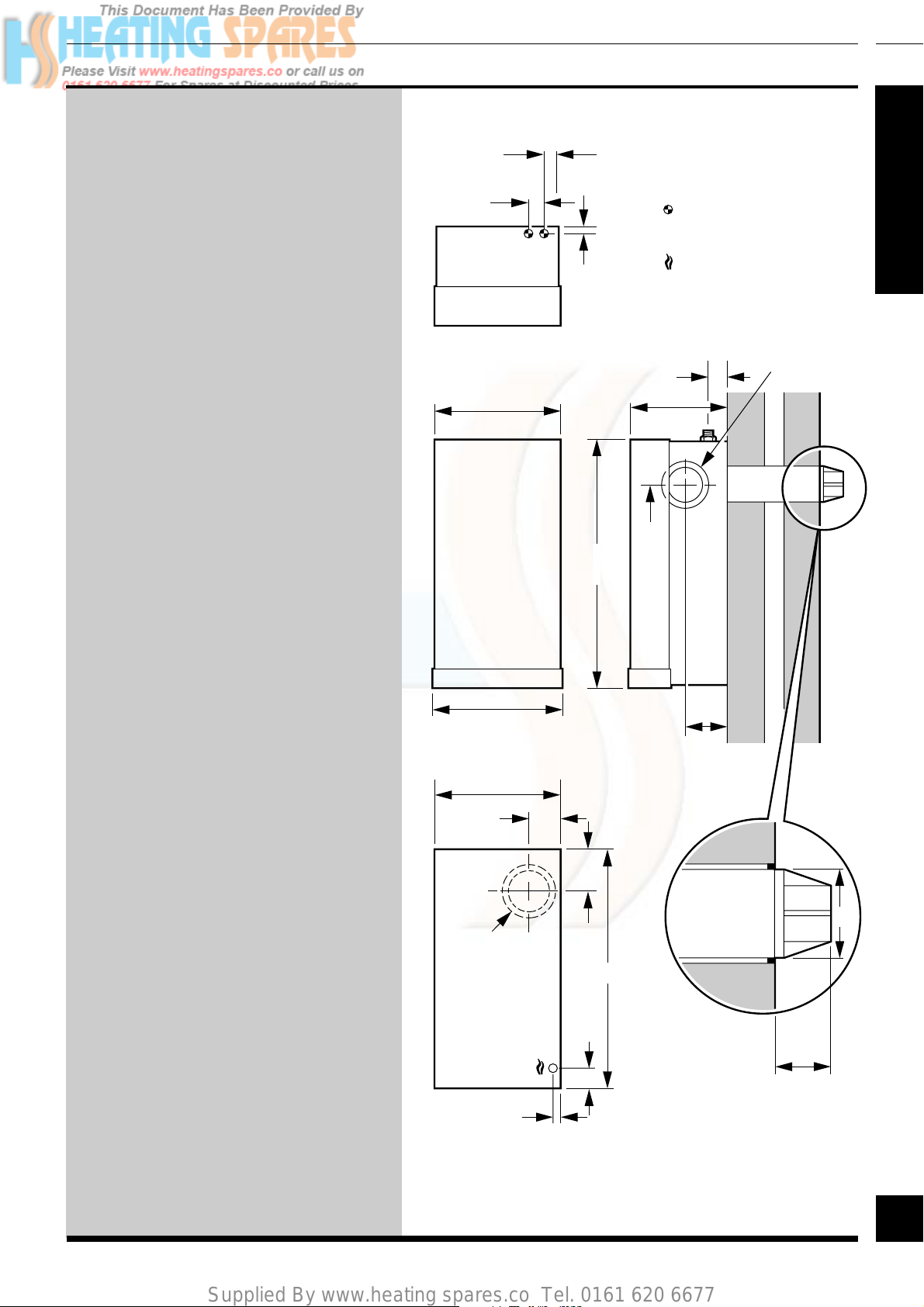
70
TOP VIEW
R F
55
35
WATER CONNECTIONS
28mm COMPRESSIONS
GAS CONNECTION
Rc1/2(1/2"B.S.P.T.)
SIDE
40
FLUE
OUTLET
1
3060
SECTION
This boiler is for use on natural gas
(G20) as distributed in the United
Kingdom and cannot be used on any
other gas.
Wherever possible, all materials,
appliances and components to be used
shall comply with the requirements of
applicable British Standards.
Where no British Standard exists,
materials and equipment should be fit for
their purpose and of suitable quality and
workmanship.
This boiler must have fully pumped
circuits, but is suitable for use with open
vented or sealed water systems.
This boiler is not suitable for outdoor
locations.
Sheet Metal Parts
450
458
FRONT VIEW
445
155
285315
130
700728
125
SIDE VIEW
WARNING. When installing or
servicing the boiler care should be taken
when handling sheet metal parts to avoid
any possibility of personal injury.
REAR
FLUE
OUTLET
Statutory
Requirements
The installation of the boiler MUST be
carried out by a competent person in
accordance with the relevant
requirements of the current issue of:
Manufacturer’s instructions supplied.
FRONT VIEW
BOILER OUTLINE
ALL DIMENSIONS ARE IN MILLIMETRES
3
15
125
50
687
FLUE
TERMINAL
DETAIL
102
63
3
220692C
Page 4

Supplied By www.heating spares.co Tel. 0161 620 6677
1
The Gas Safety (Installation and Use)
Regulations, The Building Regulations,
The Building Standards (Scotland)
Regulations, (applicable in Scotland)
Local Water Company Bye-laws, Health
and Safety at Work Act, Control of
Substances Hazardous to Health, The
SECTION
Electricity at Work Regulations and any
applicable local regulations.
Detailed recommendations are
contained in the current issue of the
following British Standards and Codes
of Practice, BS6798, BS5440 Part 1 and
2, BS6700, BS5449, BS6891, BS4814,
BS7074 Part 1 and 2, BS5446, BS7478,
BS7593, BS7671.
Manufacturer’s notes must not be taken
as overriding statutory requirements.
General
B.S.I. Certification
The boiler is certificated to the current
issue of BS6332 Part 1, invoking the
current issue of BS5258 Part 1 for
performance and safety. It is, therefore,
important that no alteration is made to
the boiler without permission, in
writing, from Hepworth Heating Ltd.
Any alteration that is not approved by
Hepworth Heating Ltd., could invalidate
the B.S.I. Certification of the boiler, the
warranty and could also infringe the
current issue of the Statutory
Requirements.
CE Mark
The CE Mark on this appliance shows
compliance with Directive 90/396/EEC
on the approximation of the Laws of the
Member States relating to appliances
burning gaseous fuels.
The CE Mark on this appliance shows
compliance with Directive 73/23/EEC
on the harmonization of the Laws of the
Member States relating to electrical
equipment designed for use within
certain voltage limits.
4
220692C
4
Page 5

Supplied By www.heating spares.co Tel. 0161 620 6677
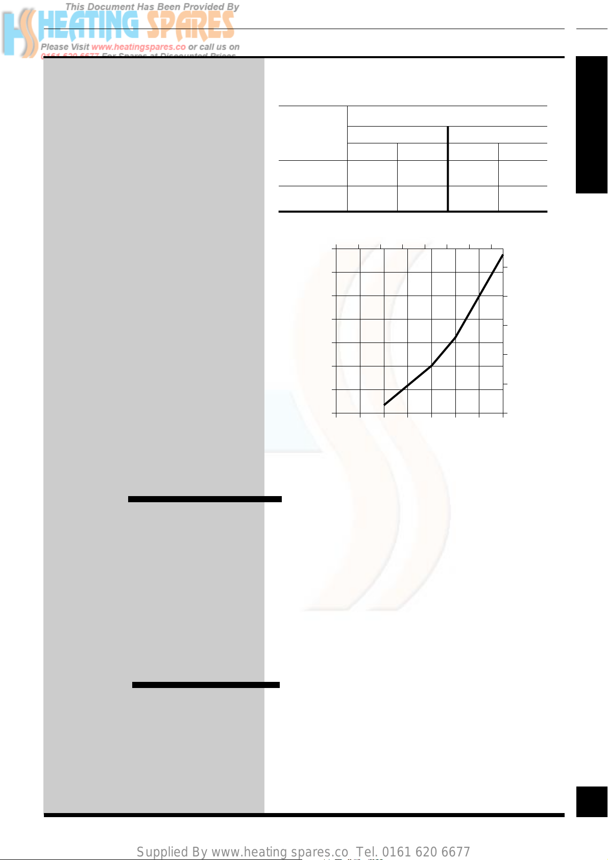
Range Rating
The boiler is range rated and may be
adjusted to suit individual system
requirements, refer to the relevant
column of the table.
General
Range Rating K.F.B K.F.B
Nominal min
Heat med
Input max
(Gross)
Nominal min
Heat med
Ouput max
Burner min
Setting med
Pressure max
Btu/h 64935 78947
kW 19.03 23.14
Btu/h 70064 84416
kW 20.54 24.74
Btu/h 75000 89709
kW 21.98 26.29
Btu/h 50000 60000
kW 14.66 17.59
Btu/h 55000 65000
kW 16.12 19.05
Btu/h 60000 70000
kW 17.59 20.52
in wg 4.2 4.6
mbar 10.6 11.4
in wg 4.9 5.2
mbar 12.2 13.0
in wg 5.6 5.9
mbar 14.0 14.6
Space Saver Space Saver
60 70
1
SECTION
Data T able
Data Label Position
Space Saver Space Saver
Model K.F.B K.F.B
60 70
Lifting 32.4kg 32.4kg
Weight (71.4lb) (71.4lb)
Total 46.1kg 46.1kg
Weight (dry)* (101.6lb) (101.6lb)
Water 2.13 litres 2.13 litres
Content (0.47 gal) (0.47 gal)
1
Gas Rc
Connection (1/2" BSPT) (1/2" BSPT)
Water 28mm 28mm
Connection Compression Compression
Electrical 240V~50Hz fused 3A max
supply
Internal Fuse to BS4265 sheet 2. Type F1A
Fuse Rating
Power rating 55W
3038
/
2
Rc1/
* Note: The weight of the water is negligible
2
5
Space Saver K.F.B 60
G.C. Number 41 319 11
Space Saver K.F.B 70
G.C. Number 41 319 12
5
220692C
Page 6

Supplied By www.heating spares.co Tel. 0161 620 6677
1
General
Gas Supply
SECTION
Electrical Supply
The gas installation shall be in accordance with the
current issue of BS6891.
The supply from the governed meter must be of
adequate size to provide a steady inlet working
pressure of 20mbar (8in wg) at the boiler.
On completion test the gas installation for soundness
using the pressure drop method and suitable leak
detection fluid, purge in accordance with the above
standard.
WARNING. THIS BOILER MUST BE EARTHED.
All system components shall be of an approved type
and shall be connected in accordance with the current
issue of BS7671 and any applicable local regulations.
Connection of the boiler and system controls to the
mains supply must be through a common isolator and
must be fused 3A maximum. The method of
connection should be, preferably, an unswitched
shuttered socket outlet and 3 pin plug, both to the
current issue of BS1363.
Draining T ap
Alternatively, a double pole isolating switch may be
used, provided it has a minimum contact separation
of 3mm in both poles. The isolator should be clearly
marked showing its purpose. See also Section 6,
Electrical Connection and System Controls.
Wiring to the boiler must be to the current issue of
BS6500 Table 16, not less than 0.75mm2 (24/
0.20mm).
The boiler is provided with a draining tap at the
lower right hand side for draining the heat exchanger
in the event of the boiler being out of use during
freezing conditions.
A draining tap must also be provided at the lowest
points of the system which will allow the entire
system and hot water cylinder to be drained.
Draining taps shall be to the current issue of BS2879.
Safety V alve
A safety valve need not be fitted to an open vented
system.
6
220692C
6
Page 7
Supplied By www.heating spares.co Tel. 0161 620 6677
Water Systems
2
Notes: Open Vented
and Sealed Water
Systems
Pump
See chart for pressure drop of the boiler.
The pump should be fitted in the flow
pipe from the boiler and have isolating
valves each side, integral if possible.
The variable duty pump should be set to
give a temperature difference of 11oC
(20oF) between flow and return with the
thermostat set at “MAX” which is about
82oC (180oF).
High resistance microbore systems may
require a higher duty pump.
UNIT
litre / min.
gal / min.
1400
1200
1000
800
600
400
WATER FLOW RATE
At 11˚C (20˚F) differential
HEAT SETTING
Min.
60 70
19.1
4.2
Flow rate (gallons / minute)
1234567
0
22.9
5.0
60 70
22.9
5.0
Max.
26.7
5.9
50
40
30
20
4778
SECTION
Bypass
200
0
Water pressure drop (mm head of water)
PRESSURE DROP OF BOILER
A BYPASS MUST BE FITTED, see also Section 7.
The flow through the boiler must not be allowed to fall
below......
Space Saver K.F.B 60 - 12.6 litres/min (2.8 galls/min)
Space Saver K.F.B 70 - 14.76 litres/min (3.2 galls/min)
Where the water system can allow the boiler and pump
to operate on bypass only, the bypass must be at least
2.0metres away from the boiler.
0 5 10 15 20 25 30 35
Flow rate (litres / minute)
10
0
Water pressure drop (inches head of water)
Inhibitor
If an inhibitor is to be used refer to the current issue of
BS5449 and BS7593, contact a manufacturer for their
recommendations as to the best product to use.
When using in an existing system take special care to
drain the entire system, including the radiators, then
thoroughly cleaning out before fitting the boiler whether
or not adding an inhibitor
7
7
220692C
Page 8
Supplied By www.heating spares.co Tel. 0161 620 6677
1
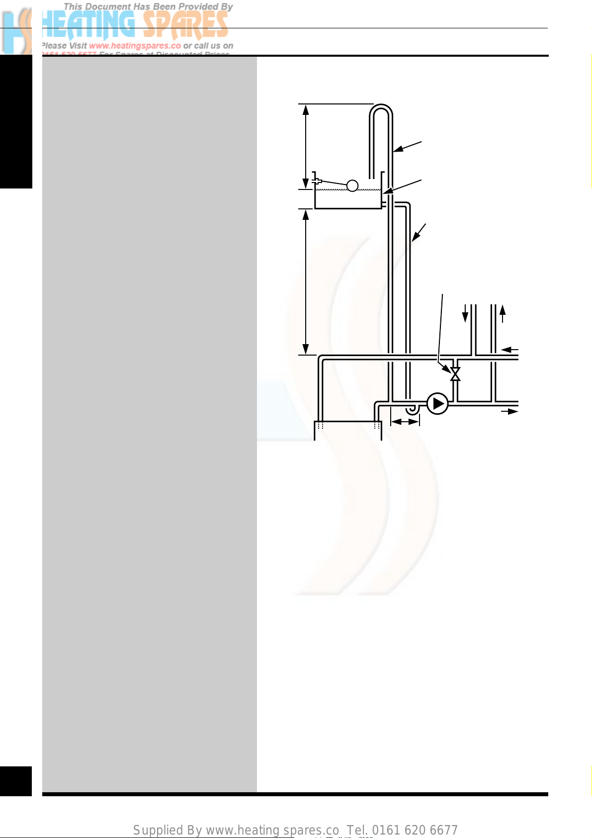
Water Sysems (Open Vented)
Open (Vented) Water
System
For an open (vented) system the boiler
must be supplied from an unrestricted
water supply taken from a feed and
expansion cistern situated at a
SECTION
maximum height of 27.5 metres (90ft)
above the boiler.
The cold feed supply must be 15mm
minimum size.
The vent must rise continuously and be
unrestricted.
It is important that the relative positions
of the pump, cold feed and open vent
are as shown.
Domestic Hot Water
Cylinder
450mm
MIN.
HEIGHT
1metre MIN.
27.5metres MAX.
Open (vented) system.
Recommended
relationship between
pump, cold feed and
vent.
UNRESTRICTED
CONTINUOUSLY
22mm (MIN) VENT
FEED AND
EXPANSION
CISTERN
15mm (MINIMUM)
UNRESTRICTED
COLD FEED
22mm (MINIMUM)
BY-PASS WITH
LOCKSHIELD VALVE
RET.
RET.
CYLINDER
2886
FLOW
The hot water cylinder must be of the
double feed fully indirect type. Not the
self priming type.
BOILER
PUMP
HEATING
FLOW
150mm
MAX
8
220692C
8
Page 9

Supplied By www.heating spares.co Tel. 0161 620 6677
Water Systems (Sealed)
Sealed W ater Systems
The installation must comply with the
appropriate requirements of the current
issue of BS5449, BS6798, BS4814 and
BS7074 Part 1 and 2.
See the diagrammatic layout.
3 LITRES (0.66 gal)
MAKE-UP BOTTLE
(if required)
AUTO
AIR
NONRETURN
VALVE
VENT
2
2888
AIR
RELEASE
POINT
SECTION
Safety V alve
A safety valve must be fitted to a sealed
system.
It shall be preset, non-adjustable with a
lift pressure of 3bar, incorporating
seating of a resilient material, a test
device and a connection for drain.
The drain from the safety valve must be
routed clear of any electrical fittings
and positioned so that any discharge can
be seen.
Expansion V essel
FILLING POINT
CIRCULATING
PUMP
PRESSURE
GAUGE
EXPANSION
VESSEL
(Make-up
alternatives)
FLOW
LOCKSHIELD
CIRCUIT
HEATING
RETURN
22mm (min)
BYPASS
WITH
VALVE
DRAIN
COCK
SAFETY
VALVE
BOILER
A diaphragm type expansion vessel, conforming to the
current issue of BS4814 (see also BS7074 Part 1 and 2)
must be connected at a point close to the inlet side of the
circulating pump, see the diagrammatic layout, unless
laid down differently by the manufacturer.
The expansion vessel volume depends on the total water
system volume and the initial system design pressure.
For any system an accurate calculation of vessel size is
given in the current issue of BS7074 Part 1.
Example: For an initial system design pressure of
0.7bar, the minimum total vessel volume required is
0.063xTotal System volume.
Note. A higher initial design pressure requires a larger
volume expansion vessel.
Guidance on vessel sizing is also given in the current
issue of BS5449 and BS7074 Part 1.
The charge pressure must not be less than the static head
of the system, that is, the height of the highest point of
the system above the expansion vessel.
The water capacity of the boiler is given in the Data
Table.
9
220692C
9
Page 10

Supplied By www.heating spares.co Tel. 0161 620 6677
2
Water Systems (Sealed)
Pressure Gauge
A pressure gauge with a set pointer and
covering at least 0 to 4bar (0 to 60lb in2)
shall be fitted permanently to the
system in a position where it can be
seen when filling the system.
SECTION
Domestic Hot Water
Cylinder
SINGLE FEED INDIRECT
CYLINDERS ARE NOT SUITABLE
The hot water cylinder must be of the
indirect coil type. It must be suitable
for working at a gauge pressure of
0.35bar above the safety valve setting.
UNVENTED
Where a storage system will not have a
vent to atmosphere the installation must
comply with the Building Regulations
and the local Water Company bylaws,
see also the current issue of BS5546
and BS6700.
METHOD 1
TEMPORARY
HOSE
SUPPLY
PIPE
METHOD 2
TEMPORARY
HOSE
SUPPLY
PIPE
METHOD 3
CISTERN
HOSE
UNIONS
SUPPLY STOP
VALVE
DOUBLE CHECK
VALVE ASSEMBLY
HOSE
UNIONS
SUPPLY STOP
VALVE
OVERFLOW
SERVICING
VALVE
COMBINED
CHECK VALVE
AND VACUUM
BREAKER
SERVICING
VALVE
SERVICING
VALVE
PRESSURE
REDUCING
VALVE
0051M
HEATING
SYSTEM
HEATING
SYSTEM
HEATING
SYSTEM
10
If fitting into an existing system the
local authority must be informed.
Water Make Up
Provision should be made for replacing
water loss from the system using a
filling loop or a make up bottle
mounted in a position higher than the
top point of the system, connected
through a non-return valve to the return
side of either the heating circuit or the
hot water cylinder.
Alternatively, provision for make up
can be made by pre-pressurisation of
the circuit.
SUPPLY
STOP VALVE
SUPPLY
PIPE
HOSE
UNIONS
DOUBLE CHECK
VALVE ASSEMBLY
Filling Sealed Water
Systems
Provision for filling the system at low level
must be made. Three methods are shown in the
diagram. There must be no permanent
connection to the mains water supply, even
through a non-return valve.
220692C
10
Page 11
Supplied By www.heating spares.co Tel. 0161 620 6677
The boiler may be installed in any room
although particular attention is drawn to
the requirements of the current issue of
BS7671 with respect to the installation
of a boiler in a room containing a bath
or shower. Any electrical switch or
boiler control using mains electricity
should be so situated that it cannot be
touched by a person using the bath or
shower. The electrical provisions of the
Building Standards (Scotland) are
applicable to such installations in
Scotland.
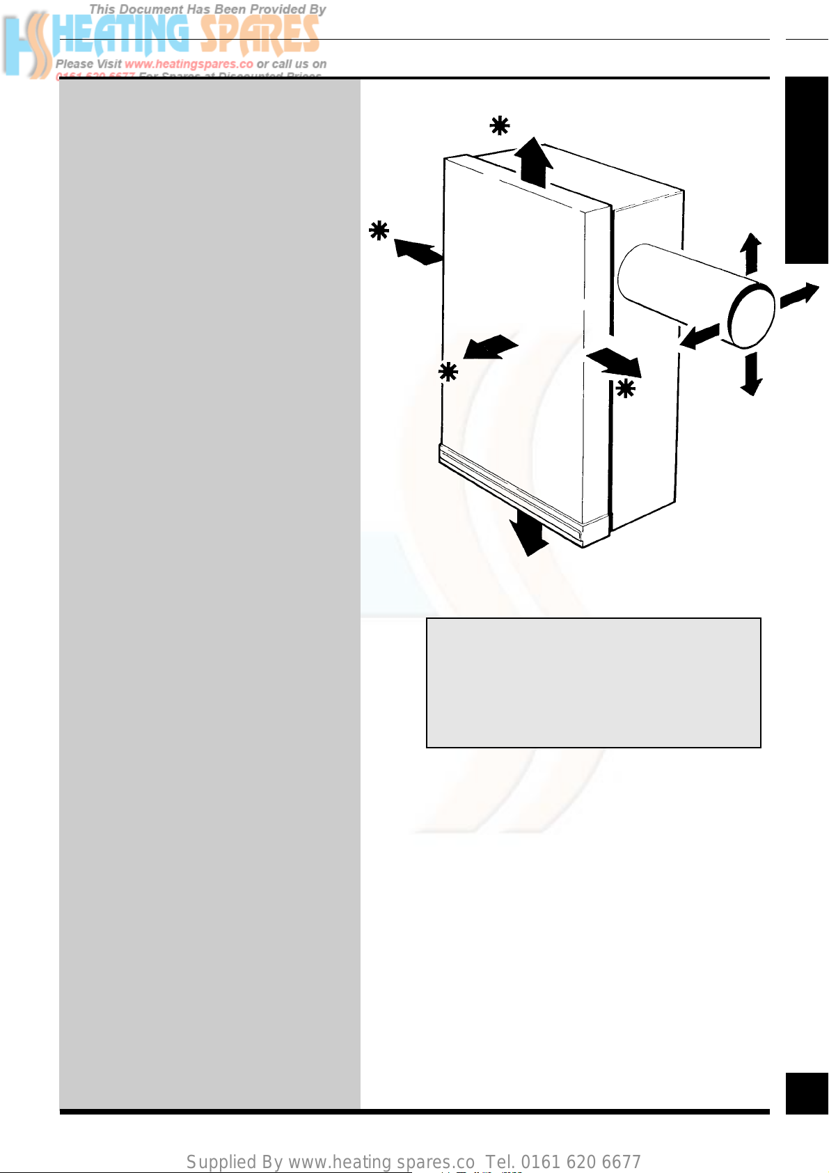
Boiler Location
10mm
70mm
5mm
3
2891
SECTION
5mm
The boiler must be mounted on a flat
wall which is sufficiently robust to take
its complete weight, see Data Table.
Boiler Clearances
The boiler must be positioned so that at
least the minimum operational and
servicing spaces are as shown.
500mm
10mm
100mm
✽
WHERE EXTERNAL ACCESS TO THE
5mm
FLUE IS NOT PRACTICAL THEN
CLEARANCE MUST BE ADEQUATE
TO PERMIT INSTALLATION OFF THE
FLUE ASSEMBLY
5mm
11
11
220692C
Page 12

Supplied By www.heating spares.co Tel. 0161 620 6677
2
Boiler Location
Timber Frame
Buildings
SECTION
Cupboard or
Compartment
Ventilation
Where the boiler is fitted in a cupboard
or compartment, permanent high and
low level ventilation must be provided.
The ventilation areas required are given
in the Table.
Where the installation of the boiler will
be in an unusual location, special
procedures are necessary, refer to the
current issue of BS6798 for guidance.
A compartment used to enclose the
boiler must be designed and
constructed specifically for this
purpose.
If the boiler is to be installed in a timber frame
building, it should be fitted in accordance with the
British Gas Publication “Guide for Gas Installation
in Timber Framed Housing” reference DM2. If in
doubt, seek advice from the local gas undertaking or
Hepworth Heating Ltd.
S P A C E S A V E R K . F . B 6 0
VENTILATION HIGH LEVEL LOW LEVEL
REQUIREMENTS VENT AREA VENT AREA
FROM ROOM
OR SPACE
FROM
OUTSIDE
198cm2 (30in2) 198cm2 (30in2)
99cm2 (15in2) 99cm2 (15in2)
An existing cupboard or compartment
modified for the purpose may be used.
Refer to the current issue of BS6798 for
guidance.
The doorway opening should be of
sufficient size to allow for easy removal
of the boiler.
S P A C E S A V E R K . F . B 7 0
VENTILATION HIGH LEVEL LOW LEVEL
REQUIREMENTS VENT AREA VENT AREA
FROM ROOM
OR SPACE
FROM
OUTSIDE
237cm2 (36in2) 237cm2 (36in2)
119cm2 (18in2) 119cm2 (18in2)
12
220692C
12
Page 13

Supplied By www.heating spares.co Tel. 0161 620 6677
Flue and Ventilation
The flue must be installed in accordance
with the current issue of BS5440 Part 1.
The boiler must be installed so that the
terminal is exposed to the external air.
4
0103M
A
C
It is important that the position of the
terminal allows the free passage of air
across it at all times.
Terminal Position
The minimum acceptable spacings from
the terminal to obstructions and
ventilation openings are as shown in the
diagram.
Where the terminal is fitted within
600mm (24in) below plastic guttering
an aluminium shield 1500mm (5ft) long
should be fitted to the underside and
immediately beneath the guttering or
eaves.
Where the terminal is fitted within
450mm (18in) below eaves or painted
guttering an aluminium shield 750mm
(2ft6in) long should be fitted to the
underside and immediately beneath the
guttering or eaves.
Terminal Protection
A terminal guard is required if persons
could come into contact with the
terminal or the terminal could be
subject to damage.
If a terminal guard is required, it must
be positioned to provide a minimum of
50mm clearance from any part of the
terminal and be central over the
terminal.
A suitable terminal guard can be bought
from,
B,C
A
F
G
Car Port etc.
MINIMUM SITING DIMENSIONS
FOR FLUE TERMINALS
A DIRECTLY BELOW AN OPENABLE WINDOW, AIR VENT, 300
OR ANY OTHER VENTILATION OPENING
B BELOW GUTTER, DRAIN/SOIL PIPE 75
C BELOW EAVES 200
D BELOW A BALCONY OR CAR PORT 200
E FROM VERTICAL DRAIN PIPES AND SOIL PIPES 75
F FROM INTERNAL OR EXTERNAL CORNERS 300
G ABOVE ADJACENT GROUND OR BALCONY LEVEL 300
H FROM A SURFACE FACING THE TERMINAL 600
I FACING TERMINALS 1200
J FROM OPENING (DOOR/WINDOW) 1200
IN CARPORT INTO DWELLING
K VERTICAL FROM A TERMINAL 1500
L HORIZONTALLY FROM A TERMINAL 300
G
A
E
G
H,I
B,C
K
F
F
G
J
K
K
L
L
K
G
D
F
SPACING
SECTION
MIN.
(mm)
4783
Tower Flue Components Ltd.,
Morley Road,
Tonbridge,
Kent.
TN9 1RA
their reference K3.
13
13
220692C
Page 14

Supplied By www.heating spares.co Tel. 0161 620 6677
2
Flue and Ventilation
Flue Position and
Length
Note. If a longer flue duct is required
DO NOT extend the ducting. A special
long flue system and terminal can be
supplied and MUST be used.
SECTION
DETERMINE FLUE APPLICATION,
LENGTH, AND TERMINAL
POSITION BEFORE PROCEEDING.
Refer to the relevant diagrams in
Section 4.
For wall thickness of less than 300mm
the boiler can be fully installed from
inside.
For a wall thickness of over 300mm the
cut hole will need to be made good
from the outside.
The rear and side flue assemblies are
designed for internal installation, but
should it be necessary due to
insufficient clearances or boiler
location they can be installed from the
outside.
2876
R
Rear Flue Lengths
Distance 'R'
S T D 75mm to 692mm
1m 692mm to 1022mm
2m 1022mm to 2022mm
REAR FLUE APPLICATION
FOLLOW
FLUE INSTALLATION
step
1
step
11
SIDE FLUE APPLICATION
FOLLOW
FLUE INSTALLATION
step
6
t o
&
t o
t o
step
5
step
16
step
16
2877
S
Side Flue Lengths
Distance 'S'
S T D 75mm to 692mm
1m 692mm to 1022mm
2m 1022mm to 2022mm
14
220692C
14
Page 15
Supplied By www.heating spares.co Tel. 0161 620 6677
Flue Installation
5
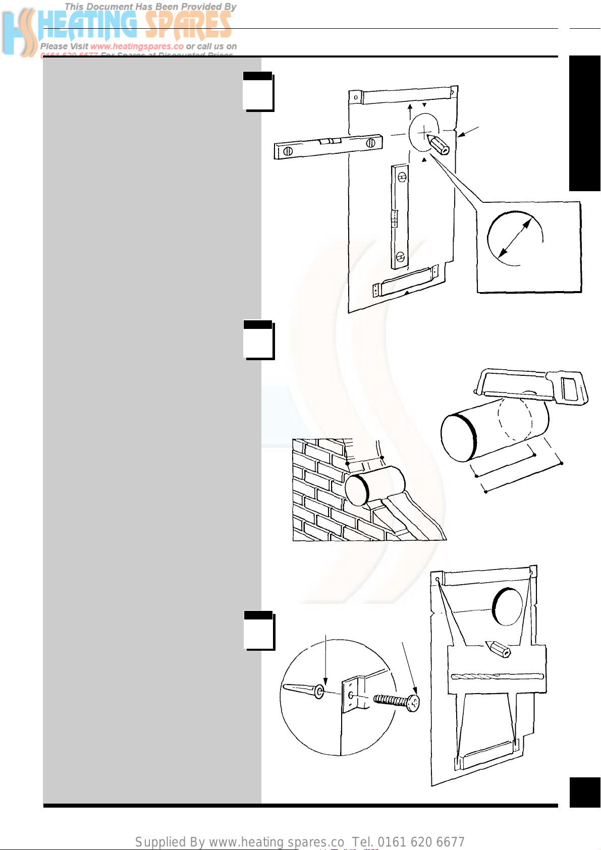
Rear Flue Application
Having selected the boiler location
with due regard to the terminal
position;
Using an adhesive tape temporarily
position the wallplate/template on the
wall.
Mark out the centre and cut the hole for
the flue using, preferably, a 115mm
minimum core drill.
If the wall thickness “Q” is less than
300mm cut the wall sleeve to the
required length.
step
2892
1
WALLPLATE/
TEMPLATE
SECTION
115mm
MINIMUM
HOLE
step
2
Fit the wall sleeve.
Make good around the wall sleeve at
both internal and external wall faces
(through the wall sleeve if internal
access only is available).
If the wall thickness “Q” is greater than
300mm the wall sleeve must be fitted
flush with the INSIDE wall face. If the
inner end of the sleeve sticks out into a
cavity then, if desired, the wall sleeve
can be trimmed back to the depth of the
inner skin of the brickwork. Make good
at the internal wall face, leave the
external wall face until later.
Reposition the wallplate/template
ensuring alignment with the flue hole.
Mark the top and bottom boiler
mounting hole positions.
step
3
WALLPLUG
Q
No. 10x11/2in
SCREW
Q
300mm MAX
LENGTH
Remove wallplate/template, drill holes
and then secure wallplate/template to the
wall with the fittings provided in the
loose items pack.
15
5.5mm DRILL SIZE
15
220692C
Page 16

Supplied By www.heating spares.co Tel. 0161 620 6677
5
Flue Installation
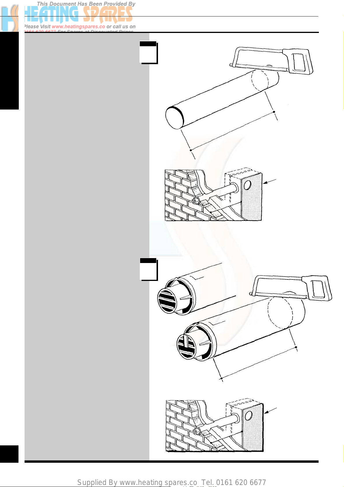
Flue Duct (Standard
or Long)
Mark the duct to the length
“Q”+11mm then cut square and
remove any burrs.
SECTION
Air Duct/Terminal
(Standard or Long)
step
4
step
5
2893
Q+11mm
Q
Mark the duct to the length “Q”+13mm
then cut square and remove any burrs.
STANDARD, 1 METRE AND 2 METRE FLUE
TERMINAL KFB 70 ONLY.
1 METRE AND 2 METRE FLUE TERMINAL
KFB 60 ONLY
1m 2m FLUE
TERMINAL
STANDARD
FLUE TERMINAL
Q+13mm
Continue at
step
11
16
220692C
16
Q
Page 17

Supplied By www.heating spares.co Tel. 0161 620 6677
Flue Installation
5
Side Flue Application
Having selected the boiler location,
with due regard to boiler clearances
and the terminal position.
Position the wallplate/template on the
wall. Mark the top and bottom boiler
mounting hole positions.
Remove the wallplate/template, drill
the holes and then secure the wallplate/
template with the fittings provided.
Mark and extend the flue horizontal
centre line to the corner of the
adjacent surface.
step
6
step
7
WALLPLUG
2894
No. 10x11/2in
SCREW
SECTION
5.5mm DRILL SIZE
125mm
Mark out and cut the hole for the flue
using, preferably, a 115mm minimum
core drill.
If the wall thickness “Q” is less than
300mm cut the wall sleeve to the
required length.
Fit the wall sleeve.
Make good around the wall sleeve at
both the internal and external wall
faces (through the wall sleeve if
internal access only is available).
If the wall thickness “Q” is greater than
300mm the wall sleeve must be fitted
flush with the internal wall face.
step
8
115mm
MINIMUM
HOLE
Q
Q
Make good at the internal wall face,
leave the external wall face until later.
If the inner end of the sleeve sticks out
into the cavity then, if desired, the wall
sleeve can be trimmed back to the depth
of the inner skin of the brickwork.
17
300mm MAX
LENGTH
17
220692C
Page 18
Supplied By www.heating spares.co Tel. 0161 620 6677
5
Flue Installation
Flue Duct
(Standard or Long)
Mark the duct to length “S”+11mm
then cut square and remove any burrs.
SECTION
step
2895
9
S+11mm
WALLPLATE
/TEMPLATE
S
Terminal/Air Duct
(Standard or Long)
Mark the duct to the length “S”+13mm
then cut square and remove any burrs.
STANDARD 1METRE AND 2 METRE FLUE
TERMINAL KFB 70 ONLY.
1 METRE AND 2 METRE FLUE TERMINAL
KFB 60 ONLY
step
10
1m 2m FLUE
TERMINAL
STANDARD
FLUE TERMINAL
KFB 60
S+13mm
18
220692C
18
WALLPLATE
/TEMPLATE
S
Page 19

Supplied By www.heating spares.co Tel. 0161 620 6677
Flue Installation
5
Air Duct/Terminal and
Flue Duct Assembly
Locate the flue duct into the air duct/
terminal.
Place the sealant from the loose items
pack onto the flue manifold.
Fully locate the flue manifold into the
air duct/terminal and flue duct
assembly as shown, ensuring correct
alignment of the “TOP”s.
step
11
step
12
2896
SECTION
FLUE
DUCT
AIR DUCT/TERMINAL
ASSEMBLY
SEALANT
Drill two 3mm diameter holes through
the air duct/terminal and flue manifold.
Secure the air duct/terminal to the flue
manifold with the two self tapping screws
supplied in the loose items pack.
It should now not be possible to remove
the manifold.
step
13
AIR DUCT/TERMINAL
AND FLUE DUCT
ASSEMBLY
FLUE MANIFOLD
5mm
3mm DRILL SIZE
19
19
220692C
Page 20

Supplied By www.heating spares.co Tel. 0161 620 6677
5
Flue Installation
Wall Thickness up to
300mm
Fit the self adhesive foam seal provided
in the loose items pack around the air
duct/terminal at the position shown.
SECTION
Wall Thickness over
300mm
step
14
step
15
FOAM SEAL
10mm
3039
Q
FOAM SEAL
Fix the self adhesive foam seal around
the air duct/terminal such that, when
installed, the seal will be within the
wall sleeve.
If the boiler is not to be fitted for
sometime cover the hole in the wall.
On all installations push the flue
assembly into and through the wall
sleeve and hole such that it is within
the wall sleeve and does not stick out
into the room. Do not push the flue
assembly too far into the hole as it has
to be pulled back into the boiler and
secured to the keyhole fixings.
step
16
Q-25mm
Q
WALL
SLEEVE
Note: That the foam seal is a tight fit in
the wall sleeve, so either the wall
sleeve will need to be rigidly fixed in
the wall, that is, the cement has fully
set or it can be held from the other side
20
whilst inserting the flue assembly.
220692C
20
Page 21

Supplied By www.heating spares.co Tel. 0161 620 6677
Installation
6
Boiler Preparation
Remove the front panel and place it
on one side until required.
Remove and discard internal packing
piece.
Remove the inner case by releasing
the screws at the bottom and
unhooking at the top, place on one
side until required.
step
1
step
2
FRONT
PANEL
3040
SECTION
Remove the violet and red electrical
connections from the fan.
Break the air pressure switch tubes
connections.
Remove the fan/flue hood assembly by
removing the two screws one at each side.
WHEN FITTING A REAR FLUE
FOLLOW STEPS
step
4
step
t o t o&
8
step
17
step
step
21
INNER
CASE
SCREW (3)
3
AIR PRESSURE
SWITCH
TUBES
RESET
BUTTON
CLEAR
RED
WHEN FITTING A SIDE FLUE
FOLLOW STEPS
step
9
t o
step
21
ELECTRICAL
CONNECTIONS
21
FAN/FLUE
HOOD
SCREW (2)
21
220692C
Page 22

Supplied By www.heating spares.co Tel. 0161 620 6677
6
Rear Flue Boiler
Installation
THE BOILER IS SUPPLIED FOR
REAR FLUE OUTLET.
Installation
step
3041
4
TOP
MOUNTING
BRACKET
SECTION
Note: To reduce the total lifting weight
remove the electrical control box and
combustion chamber assembly by
following the instructions in Section 6,
step 18 and Section 10, steps 3,5,6,7,8
and 9.
Lift the boiler into position above the
top mounting bracket, allow the boiler
to slide down the wall onto the top and
bottom wall mounting brackets.
Check the engagement by pulling the
boiler forward at its base, there should
be no forward movement.
When the boiler is correctly located
secure it with the two screws.
BOTTOM
MOUNTING
BRACKET
step
5
22
Secure the flue assembly to the boiler,
using the previously fitted dogpoint
screws noting that these are keyhole
fixings.
Make sure of the correct location of the
flue to the boiler.
220692C
step
6
LOCATION
LUG
KEYHOLE
22
Page 23

Supplied By www.heating spares.co Tel. 0161 620 6677
Installation
6
Fit fan/fluehood assembly by
engaging the fan outlet extension
over the flue manifold spigot.
Secure the fluehood assembly to the
heat exchanger with the screws
previously removed.
step
7
FAN
OUTLET
EXTENTION
3042
FLUE
MANIFOLD
SPIGOT
SECTION
If removed, refit the control box/
combustion chamber by reversing the
instructions in Section 6, step 18 and
Section 10, steps 3,5,6,7,8 and 9.
Reconnect the violet and red electrical
connections to the fan, the polarity of
the connections is not important.
Reconnect the air pressure switch tubes
as shown.
step
8
ELECTRICAL CONNECTIONS
WHITE
RED
RED
AIR
PRESSURE
SWITCH
TUBES
Continue at
step
17
23
23
220692C
Page 24

Supplied By www.heating spares.co Tel. 0161 620 6677
6
Installation
Side Flue Boiler
Installation
Remove the appropriate blanking plate
on the casing and fit it to the rear flue
SECTION
outlet.
Remove the fan assembly from the
fluehood assembly, by removing the
two screws.
Partially refit the securing screws into
the fan.
Turn the fan assembly to the required
flue outlet direction.
step
9
step
10
REAR VIEW
GASKET
FAN REAR
OUTLET
EXTENTION
3043
BLANKING
PLATE
FAN SECURING
SCREW
FLUE HOOD
ASSEMBLY
Fit the flue hood over the partially
fitted securing screws in the special
key hole slot sandwiching the gaskets
and spacer between, take care not to
damage the gaskets.
Turn the flue hood in the direction
shown.
Remove and discard the fan rear
outlet extension from the fan by
releasing the clip.
Fit the fan side outlet extension,
supplied in the loose items pack.
Secure with the clip previously
removed.
step
11
GASKET
SPACER
GASKET
RIGHT HAND
FLUE HOOD
ASSEMBLY
FAN SECURING SCREW (4)
KEYHOLE SLOT
24
220692C
24
GASKETS
AND
SPACER
Page 25

Supplied By www.heating spares.co Tel. 0161 620 6677
Installation
6
Note: To reduce the total lifting
weight remove the electrical control
box and combustion chamber
assembly by following the instructions
in Section 6, step 18 and Section 10,
steps 3,5,6,7,8 and 9.
Lift the boiler into position above the
top mounting bracket, allow the boiler
to slide down the wall onto the top and
bottom wall mounting brackets.
Check the engagement by pulling the
boiler forwards at its base, there should
be no forwards movement.
step
12
FAN SIDE
OUTLET
EXTENSION
THIS END
TO FAN
3044
RIGHT HAND
FLUE HOOD
ASSEMBLY
SECTION
LEFT HAND
FLUE HOOD
ASSEMBLY
When the boiler is correctly located
secure it with the two screws.
step
13
TOP
MOUNTING
BRACKET
BOTTOM
MOUNTING
BRACKET
25
25
220692C
Page 26
Supplied By www.heating spares.co Tel. 0161 620 6677
6
Installation
Secure the flue assembly to the boiler,
using the previously fitted dogpoint
screws noting that these are keyhole
fixings.
Take the beige/grey sealant from the
SECTION
loose items pack and place firmly
around the internal spigot of the flue
manifold.
Make sure of the correct location of the
flue and boiler.
If removed, refit the control box/
combustion chamber by reversing the
instructions in Section 6, step 18 and
Section 10, steps 3,5,6,7,8 and 9.
Loosely fit one extended brass
fluehood/fan assembly screw to the
heat exchanger on the side that the
flue exits. Slide the fluehood/fan
assembly flange under this extended
brass screw whilst turning the assembly
to enable engagement of the fan outlet
extension onto the flue manifold spigot.
step
14
step
15
3045
BEIGE/GREY
SEALANT
FAN
OUTLET
EXTENTION
EXTENDED BRASS
FLUE HOOD FAN
ASSEMBLY SCREW
26
After fitting the fan outlet extension to
the spigot smooth the sealant over the
joint.
When correctly located, secure the
assembly by fitting the other extended
brass screw and tighten both down.
Reconnect the violet and red
electrical connections to the fan, the
polarity of the connections is not
important.
Reconnect the air pressure switch
tubes.
step
16
FLUE HOOD/
FAN ASSEMBLY
FLUE
MANIFOLD
SPIGOT
ELECTRICAL
CONNECTION(S)
RED
AIR PRESSURE
SWITCH TUBES
CLEAR
FAN
OUTLET
EXTENSION
220692C
26
Page 27
Supplied By www.heating spares.co Tel. 0161 620 6677
Installation
6
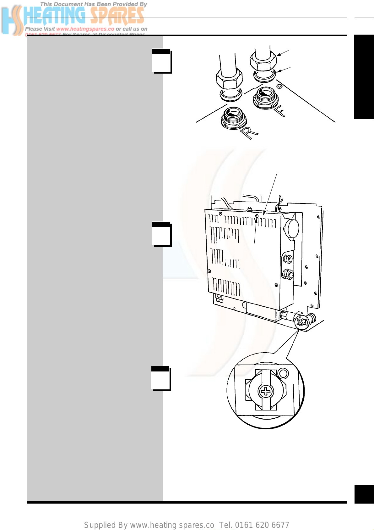
Water System
Connection
Connect the boiler to the water system
using the fittings provided in the loose
items pack.
The flow connection is on the right.
Gas Supply
Connection
Remove the electrical controls box
cover.
step
17
step
18
RETURN
ELECTRICAL
CONTROL
BOX COVER
SECURING
SCREW (4)
UNION
NUT
OLIVE
FLOW
3046
SECTION
Connect the gas supply to the gas
service cock on the boiler making
sure it is turned off.
Check for gas soundness up to the
cock, in accordance with the current
issue of BS6891.
step
19
27
INDICATOR
SLOT
(SHOWN OFF)
27
220692C
Page 28

Supplied By www.heating spares.co Tel. 0161 620 6677
6
Installation
Electrical Connection
and System Controls
SECTION
Cable Connection
The boiler must be earthed.
The incoming cables should be routed
from the right hand side of the boiler.
Remove the terminal connection plug
as shown.
Connect the incoming supply and
remote controls cables through the
restraining glands.
step
20
step
21
The electrical installation must comply with the current
issue of BS7671 and any local regulations which apply.
All controls and connections must be of the approved type.
PUMP
STRAIN
RELIEF
GLAND
TERMINAL
PLUG CONNECTION
TERMINAL CONNECTION
PLUG MAINS AND REMOTE
CONTROLS WIRING
✻ RED LINK
LONGER
EARTH LEADS
MAINS AND
SWITCH LIVE
STRAIN RELIEF
GLAND
2905
The earth conductor must be of a
greater length so that if the cable is
strained the earth is the last to become
disconnected.
Test the insulation resistance of the
mains cable to earth.
Test for polarity of the mains cables.
Check earth continuity and short circuit
of cables.
Replace the terminal connection plug.
Secure the cables in the plastic clips.
SL
✻ RED LINK
5
6
7
8
9
10
N
11
L
12
G/Y
G/Y
BLUE
BROWN
BLUE
BROWN
G/Y
CIRCULATION
PUMP
E
N
240V ~ 50Hz
PERMANENT
L
MAIN SUPPLY
N
FUSED AT 3AMP
L
E
✻ Remove RED link between 7 and 12 (switch live)
when fitting a time control etc.(if no switch is fitted
the pump will run continuously)..
28
220692C
28
✻ RED LINK
Page 29
Supplied By www.heating spares.co Tel. 0161 620 6677
Completion and Commissioning
7
System
Commissioning - All
Systems
Sealed Water
Systems Only
Commissioning should be carried out by a competent
person in accordance with the current issue of BS6798.
Make sure that the system has been thoroughly flushed
out with cold water without the pump in place. Refit
the pump, fill the system with water, making sure that
all air is properly vented from the system and pump.
Clear any airlocks and check for water soundness.
Flush the whole system without the pump in place.
Refit the pump and fill the system until the pressure
gauge registers 1.5bar (21.5lbf/in2). Clear any airlocks
and check for water soundness.
Check the operation of the safety valve, by allowing
the water pressure to rise until the valve opens.
The valve should open within +/-0.3bar (+/-4.3lbf/in2)
of 3bar (42.6lbf/in2). Where this is not possible
conduct a manual check and test.
Release cold water to initial system design pressure.
SECTION
The set pointer on the pressure gauge should be set to
the initial design pressure.
If air is present in the system, this may, in certain
circumstances, cause the overheat thermostat to trip. If
this occurs advise the user to operate the control
thermostat on a low setting until all air has been
expelled.
29
29
220692C
Page 30
Supplied By www.heating spares.co Tel. 0161 620 6677
7
Completion and Commissioning
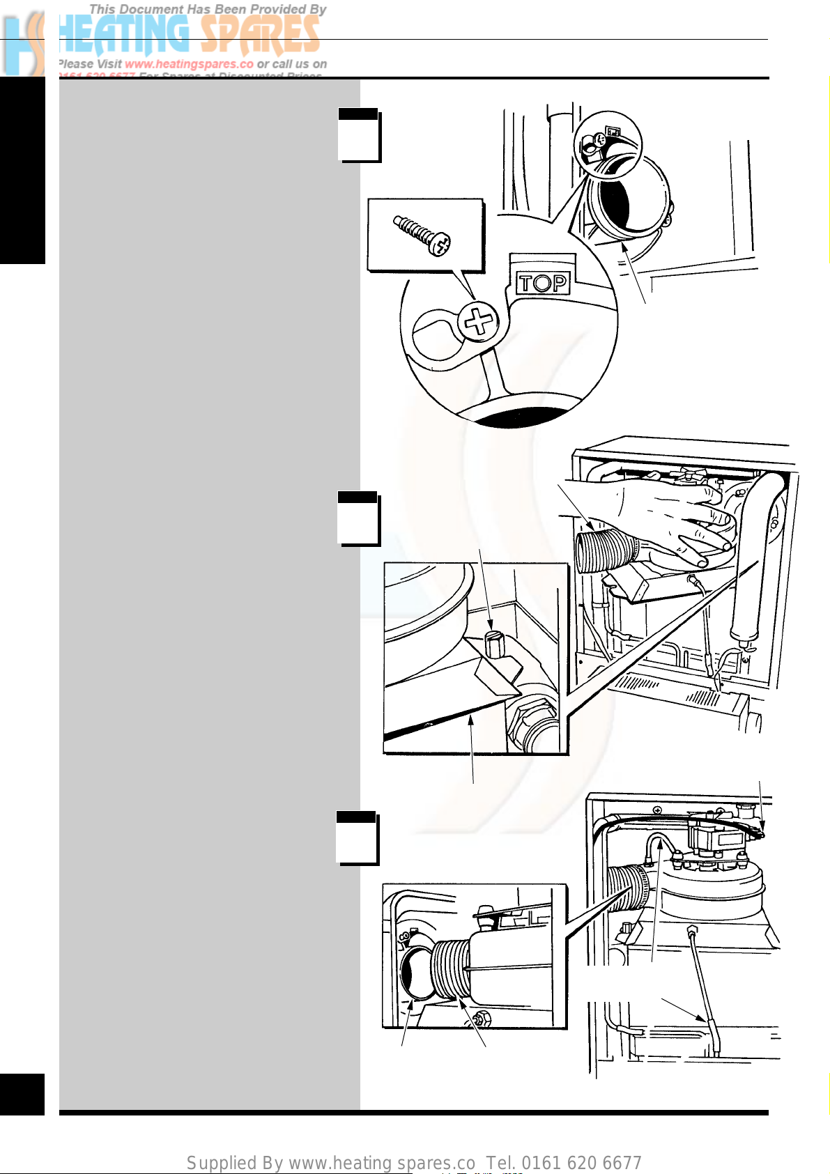
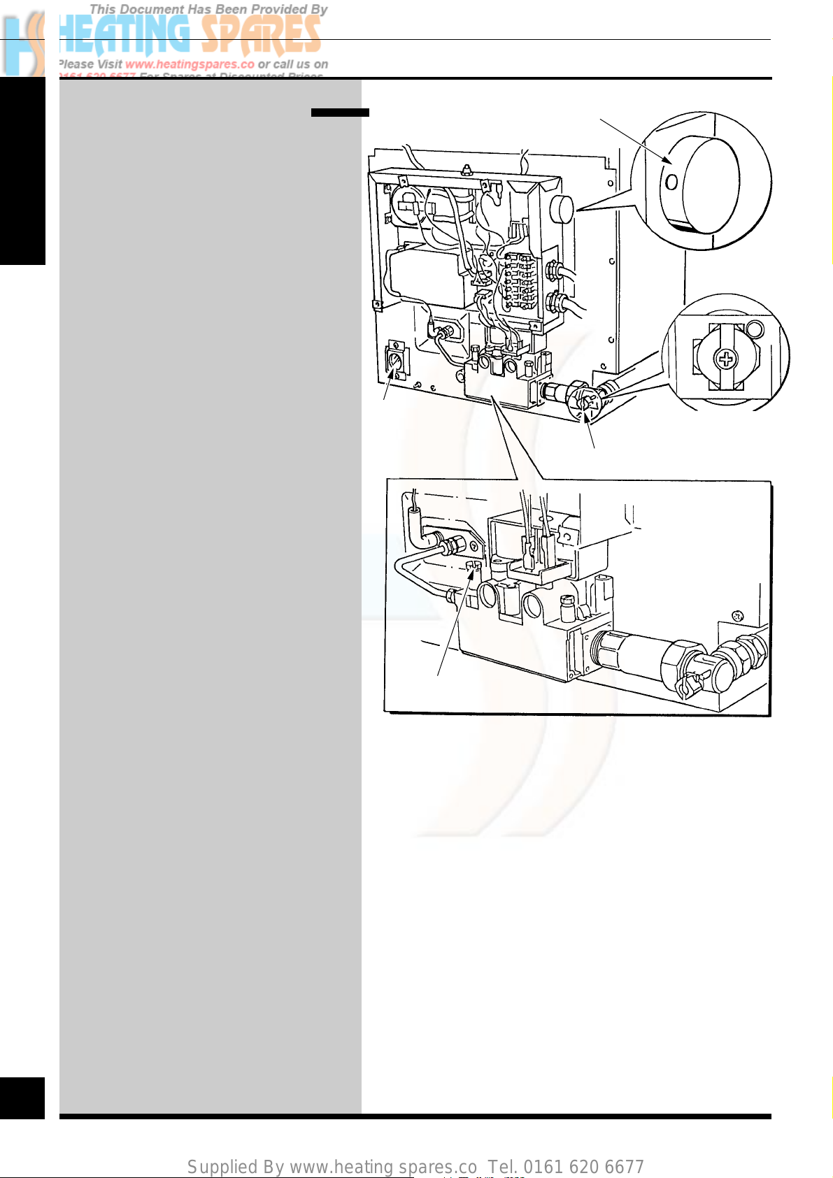
Initial Lighting and
Testing and
Adjustment
Refit the inner case, by hooking it over
SECTION
at the top and securing with the screws
previously removed, at the bottom.
Make sure that the case is correctly
fitted and sealed.
Identify the controls by reference to the
diagram.
Check that the boiler is isolated from
the electrical supply.
Make sure that the boiler thermostat is
turned to the “Off” position.
Turn the gas service cock “On”, the
indicator slot to be horizontal.
The pilot gas rate is preset and MUST
NOT be adjusted, see Servicing, Step
15.
BOILER THERMOSTAT CONTROL KNOB
(Shown in the OFF position)
VIEWING
WINDOW
GAS SERVICE
COCK
3047
INDICATOR
SLOT
(SHOWN OFF)
NOTE:
Do not adjust
any other
setting screws.
For future reference stick the self
adhesive arrow indicator from the loose
items pack, to the data label against the
rating that the boiler is going to be set
to.
Loosen the main burner pressure test
point screw and fit a suitable pressure
gauge.
Make sure that any remote controls are
calling for heat.
Switch on or connect the electrical
supply to the boiler and heating system.
Warning. The gas valve and fan
operate on MAINS voltage, terminals
will become “LIVE”.
PRESSURE
TEST POINT
30
220692C
30
Page 31
Supplied By www.heating spares.co Tel. 0161 620 6677
Completion and Commissioning
7
Testing - Electrical
Checks to ensure electrical safety should be carried
out by a competent person.
In the event of an electrical fault after installation of
the system, preliminary electrical system checks as
below should be carried out.
1. Test insulation resistance to earth of mains
cables.
2. Test the earth continuity and short circuit of all
cables.
3. Switch on the electrical supply to the boiler and
test the polarity of the mains supply.
Turn the boiler thermostat knob fully clockwise to
the maximum setting.
The lighting sequence is automatic, as follows:
The fan operates
The spark ignition operates
The pilot solenoid opens
SECTION
The pilot burner lights
The ignition spark stops
The main solenoid opens -
and after a short period of time the main burner will
light, view through window.
The main burner will remain alight until switched
off, either by the boiler thermostat or a remote
system control.
(When the boiler switches “Off”, both the pilot and
main burner go out. The automatic lighting
sequence will operate again when heat is required).
31
31
220692C
Page 32
Supplied By www.heating spares.co Tel. 0161 620 6677
7
Completion and Commissioning
Testing - Gas
With the boiler on proceed as follows:
Test for gas soundness around the boiler
gas components using a suitable leak
detection fluid, in accordance with the
current issue of BS6891.
SECTION
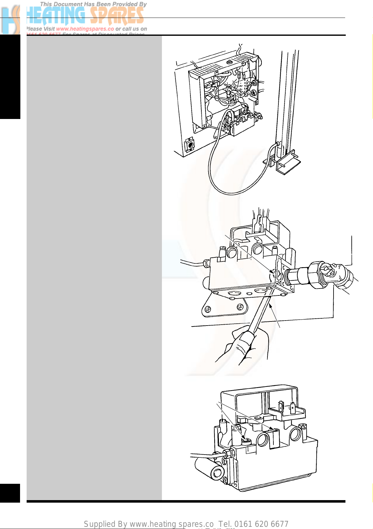
Check the main burner gas pressure at
least 10 minutes after the burner has lit,
refer to Data Label.
If necessary, adjust the gas pressure to
obtain the required setting (screw at rear
of the gas valve) turning anti-clockwise,
viewed from the front, to decrease the
pressure.
Should any doubt exist about the gas rate,
check it using the gas meter test dial and a
stop watch, at least 10 minutes after the
burner has lit, making sure that all other
gas burning appliances and pilot lights are
off.
Space Saver K.F.B 60 Approx. Gas Rate
min med max
m3/h 1.8 1.95 2.1
ft3/h 64 69 74
3048
MAIN BURNER
ADJUSTMENT
SCREW (8mm
ACROSS FLATS)
Space Saver K.F.B 70 Approx. Gas Rate
min med max
m3/h 2.2 2.4 2.5
ft3/h 78 83 89
The gas rates are for guidance only,
dependent on the heat setting.
Turn the boiler thermostat knob fully
anti-clockwise to “Off”. Remove the
pressure gauge from the test point and
refit the screw, making sure that a gas
tight seal is made.
When the boiler thermostat is turned to
the “Off” position, by hand, wait at least
30 seconds before turning “On” again.
There may be an initial smell given off
from the boiler when new, this is quite
normal and it will disappear after a short
period of time.
Refit the electrical controls box cover
with the four screws previously removed.
8mm
SPANNER
DO NOT
ADJUST
Note: The neon indicator lights on the
printed circuit board are an aid to fault
finding, for details refer to Section 11.
32
220692C
32
Page 33

Supplied By www.heating spares.co Tel. 0161 620 6677
Completion and Commissioning
7
Heating System
Check that all remote controls are working as
required.
Allow the system to reach maximum working
temperature and examine for water leaks. The
boiler should then be turned off and the system
drained off as rapidly as possible whilst still hot.
SECTION
Refill the system, vent and again check for water
soundness.
For sealed systems adjust to initial design pressure.
Any set pointer on the pressure gauge should be set
to coincide with the indicating pointer.
The overrun thermostat will keep the pump running
when the boiler shuts down, so long as the
temperature within the boiler is above a
predetermined level, providing the control
thermostat is set at maximum.
When commissioning the system the boiler should
be fired with the bypass fully closed on full service,
that is, central heating and domestic hot water. The
system should then be balanced, adjusting the pump
and lockshield valve as necessary. Having achieved
a satisfactory condition, operate the boiler with the
bypass closed on minimum load, normally central
heating only with one radiator operating in the main
living area. The valve should be opened gradually
to achieve the appropriate flow rate as quoted in
Section 2. If necessary readjust the pump.
Operational Checks
Under NO circumstances should this valve be left in
the FULLY CLOSED position.
Adjust the boiler thermostat and any system
controls to their required settings.
Do not attempt to adjust the thermostat calibration.
Operate the boiler again on full service and check
that the balancing is satisfactory, making further
adjustments as necessary to the system, radiator
valves and bypass.
On open vented systems there must be no pumping
over of water or entry of air at the vent above the
feed and expansion cistern.
If thermostatic radiator valves are fitted care must
be taken to ensure that there is an adequate flow rate
when the valves are closed. Refer to the current
issue of BS7478 on the use of thermostatic radiator
valves.
33
33
220692C
Page 34

Supplied By www.heating spares.co Tel. 0161 620 6677
8
Front Panel Assembly
Note. The front panel assembly has
been designed with a variable
adjustment to suit a range of available
kitchen furniture, 700mm-728mm high
by 285mm-315mm deep and will also
suit installations in a cupboard.
SECTION
It is delivered preset to 700mm high by
285mm deep.
Measure the height of the cupboard or
compartment, “H”.
Adjust the front panel height “H” as
necessary.
step
1
step
2
H = 700 to 728mm
W = 470mm
TOP HOLE FIXING
700 to 714mm
W
D = 285 to 315mm
3059
H
BOTTOM HOLE FIXING
714 to 728mm
Measure the depth of the cupboard or
compartment, “D”.
Adjust the front panel top mounting
bracket as necessary.
Slide the right hand side cover plate
(supplied in the fittings pack) into
position.
step
3
BOILER
MOUNTING WALL
ADJUSTMENT
SCREW
H
D
'MINUS' 1mm
34
220692C
34
FRONT
PANEL
TOP
MOUNTING
BRACKET
Page 35

Supplied By www.heating spares.co Tel. 0161 620 6677
Front Panel Assembly
8
Locate the front panel assembly.
Engage the bottom front panel
assembly slide/catch and adjust as
necessary.
step
4
step
5
2908
SECTION
ADJUSTMENT
SCREW
User Information
User Information
Instruct and demonstrate the efficient and safe
operation of the boiler, heating system and if fitted, the
domestic hot water system.
Advise the user of the precautions necessary to prevent
damage to the system and building in the event of the
heating system being out of use during frost and
freezing conditions.
Advise the user, to ensure the continued efficient and
safe operation of the boiler it is recommended that it is
checked and serviced as necessary at regular intervals.
The frequency of servicing will depend upon the
particular installation conditions and usage, but in
general once a year should be enough.
It is the law that servicing must be carried out by a
competent person.
SLIDE
ASSEMBLY
CATCH
9
SECTION
Draw attention, if applicable, to the current issue of the
Gas Safety (Installation and Use) Regulations, Section
35, which imposes a duty of care on all persons who
let out any property containing a gas appliance.
Reminder, leave these instructions with the user.
35
35
220692C
Page 36

Supplied By www.heating spares.co Tel. 0161 620 6677
10
Servicing
To ensure the continued efficient and
safe operation of the boiler it is
recommended that it is checked and
serviced as necessary at regular
intervals. The frequency of servicing
will depend upon the particular
installation conditions and usage, but in
SECTION
general once a year should be enough.
It is the Law that servicing must be
carried out by a competent person.
BEFORE STARTING A SERVICE
REMOVE THE FRONT PANEL as
shown, for Access, ISOLATE THE
BOILER FROM THE ELECTRICAL
SUPPLY AND TURN THE GAS
SUPPLY OFF AT THE GAS SERVICE
COCK, INDICATOR SLOT TO BE
VERTICAL.
Unless stated otherwise, all parts are
replaced in the reverse order to
removal.
After completing any servicing always
test for gas soundness and if necessary
carry out functional checks of controls.
step
1
step
2
step
3
SECURING
SCREW(4)
3049
FRONT PANEL
ELECTRICAL
CONTROLS
BOX COVER
INDICATOR
SLOT
(SHOWN OFF)
36
Access
Remove the electrical control box
cover by removing the four screws.
Note: As an aid to Servicing the air
pressure switch tube connection can be
used to obtain a products of combustion
reading.
Follow Steps 1, 2 and 4.
Remove the RED tube from the
connection on the air pressure switch
and insert the analyser probe into the
tube.
Switch on the electrical supply to
operate the fan and turn on the gas
supply.
On completion of the test switch off the
electrical and gas supplies and reconnect
the red tube to the air pressure switch.
Remove the inner case, by unscrewing
at the bottom and unhooking at the top.
step
4
GAS SERVICE
COCK
INNER
CASE
SCREW (3)
step
5
220692C
36
Page 37

Supplied By www.heating spares.co Tel. 0161 620 6677
Servicing
10
Cleaning the Heat
Exchanger
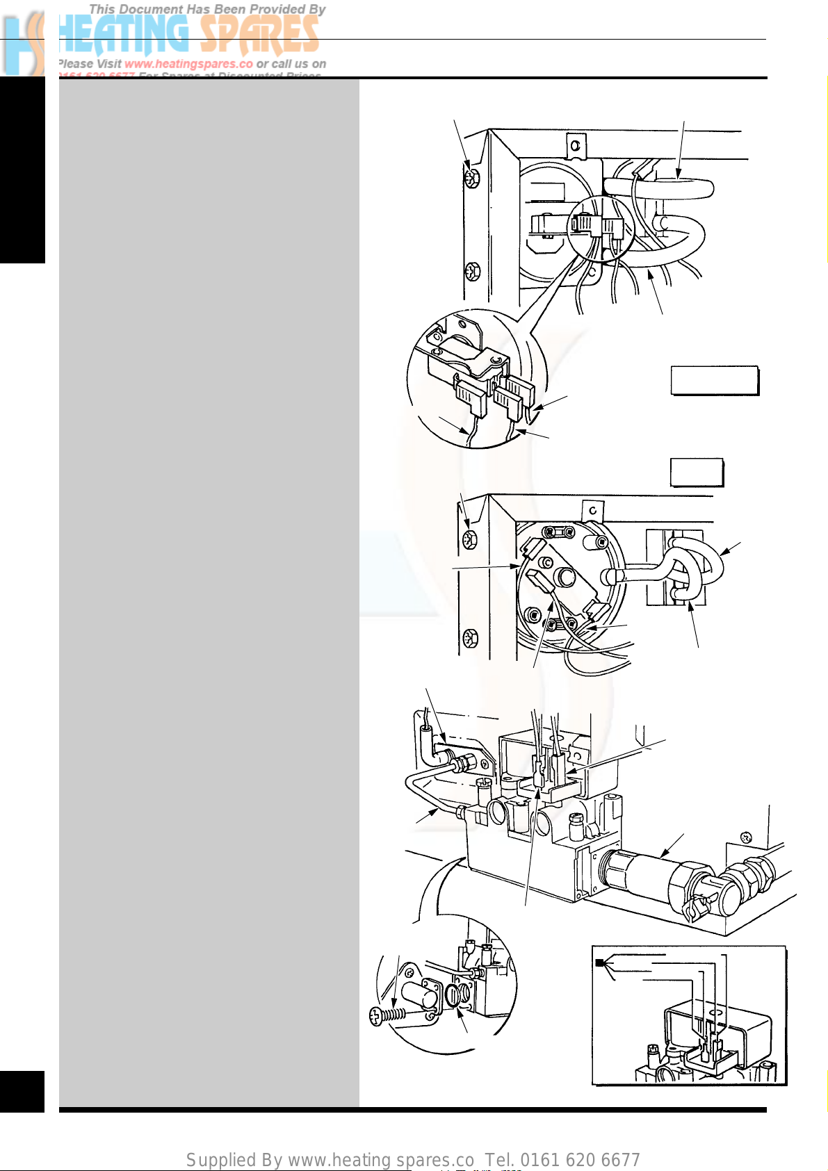
Slacken the flue hood by loosening the
extended brass screws at the left and
right hand sides.
Remove the split pin and thermostat
phials from the pocket, taking care
not to kink the capillaries.
When replacing the phials make sure
that they are still covered with heat
sink compound.
step
6
step
7
FAN/FLUE HOOD
SCREW (2)
PHIAL
POCKET
3050
SECTION
SPLIT PIN
OVERHEAT
CUT-OFF
PHIAL
Disconnect the air pressure switch
tubes.
step
8
THERMOSTAT
PHIAL
RED
AIR
PRESSURE
SWITCH
TUBES
WHITE
37
37
220692C
Page 38

Supplied By www.heating spares.co Tel. 0161 620 6677
10
Servicing
Disconnect the gas service cock at the
union connection.
Disconnect the electrical connection
plug by pulling it out from the right
hand side of the control box.
SECTION
Remove the violet and red electrical
connections on the fan and cable from
the securing clips.
Remove the electrical control box/
combustion chamber cover assembly
by removing the ten securing screws,
withdraw the complete assembly.
Slacken the air pressure pipe union and
turn through 90o.
step
9
CLIPS
FAN ELECTRICAL
CONNECTIONS
AIR PRESSURE
PIPE UNION
SECURING
SCREWS (10)
ELECTRICAL
CONNECTIONS
PLUG
3051
Remove the rear flueway cleaning
plate.
Remove the heat exchanger front
cover, by removing the eight securing
screws.
Place a sheet of paper in the base of
the combustion chamber.
Remove the three baffles.
step
10
step
11
GAS SERVICE COCK
UNION CONNECTION
REAR FLUEWAY
CLEANING PLATE
SECURING
SCREW (6)
HEAT
EXCHANGER
FRONT
COVER
38
220692C
38
BAFFLES (3)
Page 39

Supplied By www.heating spares.co Tel. 0161 620 6677
Servicing
10
The heat exchanger can now be
cleaned with a suitably sized semistiff brush, using the cleaning plate,
as shown to protect the rear
insulation panel.
DO NOT USE A BRUSH WITH
METALLIC BRISTLES.
Remove the paper and debris from
the combustion chamber.
Correctly refit the baffles previously
removed, each is marked TOP on its
upper face.
Refit the heat exchanger front cover.
Tighten down the fan flue screws.
Refit the cleaning plate.
Main Burner
Remove the main burner by releasing
the two securing nuts as shown. Brush
or vacuum away any deposits, ensure
that the flame ports are clean.
step
12
step
13
3108
50mm
SECTION
380mm MIN.
20mm
40mm
SEMI-STIFF
NYLON BRISTLES
CLEANING BRUSH
CLEANING
PLATE
PILOT
BURNER SHIELD
DO NOT USE A BRUSH WITH
METALLIC BRISTLES.
Make sure that the pilot burner shield is
located between the burner bracket as
shown.
Main Injector
The main injector can be removed
and cleaned.
When cleaning the injector do not use
a wire or sharp instrument on the
hole.
BURNER
BRACKET
INJECTOR
step
14
VIEW OF MAIN
BURNER INJECTOR
WITH BURNER REMOVED
39
SECURING
NUTS
220692C
39
Page 40

Supplied By www.heating spares.co Tel. 0161 620 6677
10
Servicing
Pilot Burner, Ignition
Electrode and Pilot
Injector
SECTION
Pull off the ignition lead at the
electrode (covered with a silicone
rubber sleeve).
Unscrew the tubing nuts at both ends
releasing the pilot pipe.
Remove the pilot burner securing
screws to release the pilot burner and
electrode assembly.
Clean the pilot burner and electrode.
Remove the pilot injector by
unscrewing it from the pilot burner,
clean it by blowing through it.
When refitting take care not to damage
the electrode and check that the spark
gap is as shown.
step
15
IGNITION
LEAD
SILICONE
RUBBER
SLEEVE
PILOT TUBING NUT
4781
PILOT
BURNER
ASSEMBLY
SECURING
SCREW (2)
PILOT
PIPE
PILOT TUBING NUT
15-20mm
SPARK GAP
3.5-4.5mm
PILOT BURNER
40
220692C
40
PILOT INJECTOR
Page 41
Supplied By www.heating spares.co Tel. 0161 620 6677
Fault Finding
11
Electrical
Important. On completion of the
service/fault finding task which has
required the breaking and remaking of
the electrical connections the earth
continuity, polarity, short circuit and
resistance to earth checks must be
repeated using a suitable multimeter.
Refer to Fault Finding, Wiring and
Functional Flow diagrams.
Electrical Supply
Failure
Failure of the electrical supply will
cause the burner to go out. Operation
will normally resume on restoration of
the electrical supply. If the boiler does
not relight after an electrical supply
failure the overheat device may need
resetting.
Remove the front panel as Section 1,
Step 1 and press the reset button on top
of the electrical controls box cover, see
diagram at Step 3. If the cut off
operates at any other time press the
reset button and the burner should
relight. If the fault persists refer to
Fault Finding Chart.
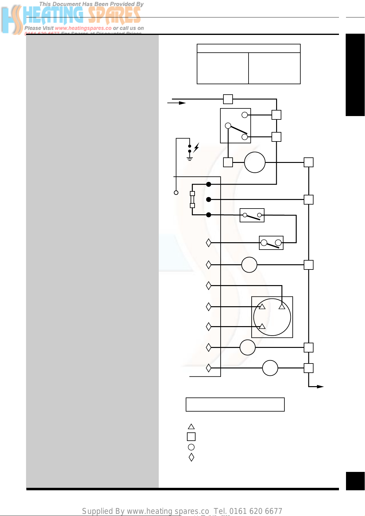
L
THERMOSTAT
SPARK
ELECTRODE
FUSE
TYPE F1
1 AMP
KEY
bk BLACK
br BROWN
b BLUE
v VIOLET p PURPLE
PUMP
OVERRUN
(L)
11
7
p
9
w
rv
AIR
PRESSURE
SWITCH
brbr
9
8
br b
PUMP
br
b
O/H CUTOFF
y
CONTROL STAT
FAN
r
bk
y
w WHITE
r RED
y YELLOW
br
7
LINK
6
2
*
12
3
3
(N/C)
r
(N/O) (C)
1
RED
(SL)
2914
SECTION
8
b
10
(N)
10
b
(N)
b
y
RED LINK may have been removed
to fit remote controls.
*
41
br
PILOT
SOLENOID
bk
MAIN
SOLENOID
AIR PRESSURE SWITCH CONNECTIONS
MAIN TERMINAL STRIP CONNECTIONS
CONTROL THERMOSTAT CONNECTIONS
PRINTED CIRCUIT BOARD CONNECTIONS
b
b
10
10
(N)
b
(N)
N
41
220692C
Page 42

Supplied By www.heating spares.co Tel. 0161 620 6677
11
Fault Finding
SECTION
AIR PRESSURE
SWITCH
C
NC NO
123
FAN
g/y
CHASSIS
EARTH
KEY:
b - BLUE
bk - BLACK
br - BROWN
v
r
r - RED
g/y - GREEN/YELLOW
- MAIN TERMINAL STRIP
- CONTROL THERMOSTAT
AIR PRESSURE SWITCH
-
NUMBER = BECK LETTER = YAMATAKE
p - PURPLE
v - VIOLET
w - WHITE
y - YELLOW
3109
OVERHEAT
CUT-OFF
CONTROL
THERMOSTAT
y
p
7
w
986
3
br
r
y
CHASSIS
EARTH
r
v
g/y
POST
42
r
y
PRINTED CIRCUIT
BOARD
SPARK
ELECTRODE
FUSE
TYPE F1
1 AMP
bk
GAS
VALVE
bk
br
g/y
b
g/y
CIRCULATION
5
6
7
8
9
10
11
12
b
br
g/y
SWITCHED
LIVE
PUMP
g/y
b
br
b
br
g/y
240V~50Hz
PERMANENT
E
N
L
N
L
E
MAINS SUPPLY
Remove RED link
FUSED 3 AMP
between 7 and 12
when fitting a time
control etc. (If no
switch is fitted the
pump will run
continuously).
220692C
42
Page 43
Supplied By www.heating spares.co Tel. 0161 620 6677
Fault Finding
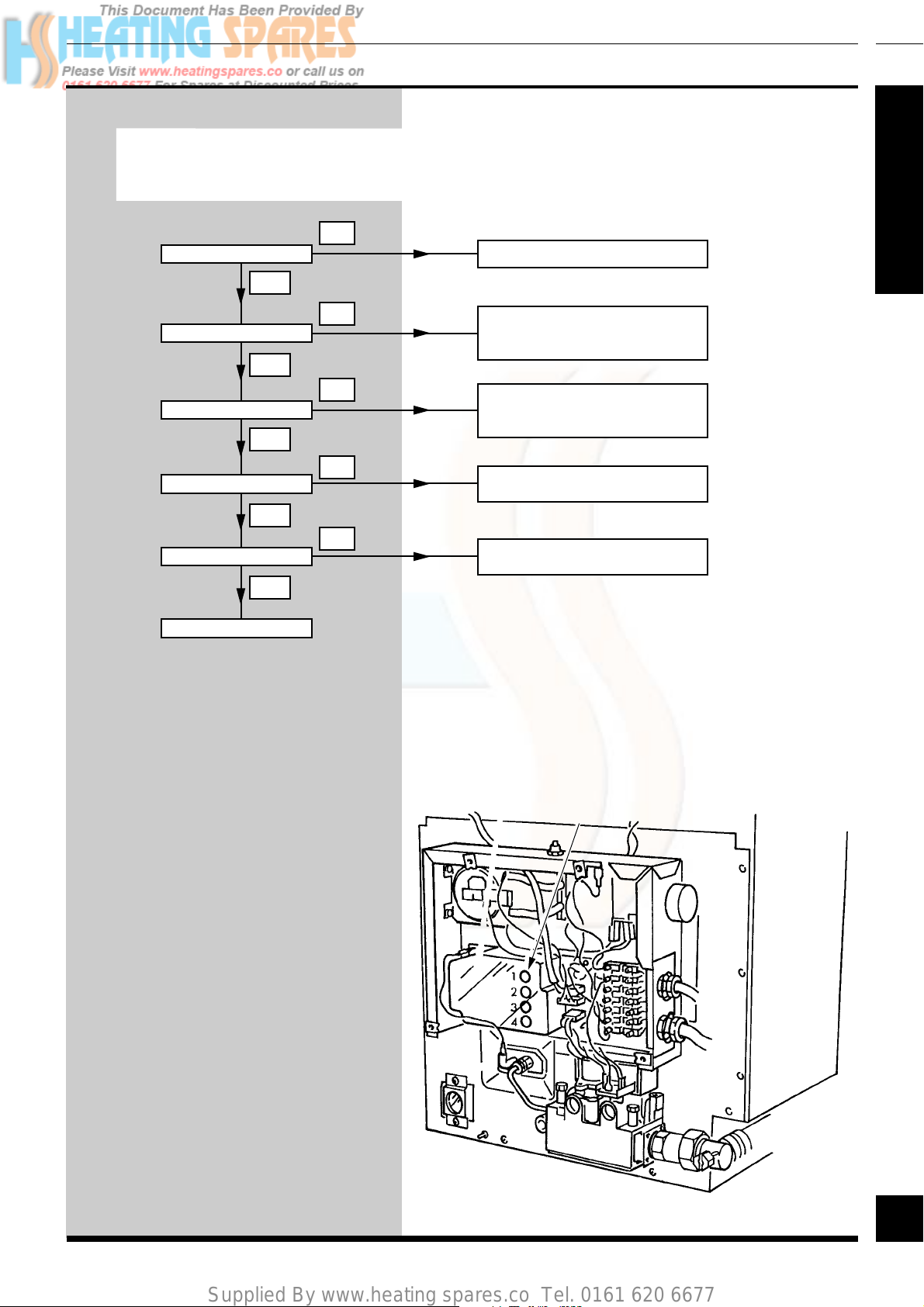
Neon Indicators - An Aid to Fault Finding
THE NEON INDICATORS ARE AN AID TO FAULT FINDING ONLY. FAILURE OF ANY OF THE NEON INDICATORS DOES NOT
WARRANT THE REPLACEMENT OF AN OTHERWISE SATISFACTORY PRINTED CIRCUIT BOARD (PCB)
Is neon 1 lit? Fault with mains supply or PCB fuse.
Overheat cut off device tripped or
thermostat, overheat cut off device
faulty - see detailed fault finding chart.
Air flow proving fault that is fan or air pressure switch see detailed fault finding chart.
Ignition, pilot or flame proving fault see detailed fault finding chart.
Gas valve / harness problem - see
detailed working? fault finding chart.
Is neon 2 lit?
Is neon 3 lit?
Is neon 4 lit?
Is main burner operating?
System satisfactory
NO
NO
NO
NO
NO
YES
YES
YES
YES
YES
11
4754
SECTION
43
NEON INDICATORS (4)
3054
43
220692C
Page 44

Supplied By www.heating spares.co Tel. 0161 620 6677
11
Before detailed checking of electrical components ensure that remote controls are calling for heat. Check the gas supply is free of obstructions and
purged of air. Check the overheat cutoff has not operated. Isolate the electrical supply and physically check ALL cables, connections and the printed
Is neon 1 lit?
YES
SECTION
Is neon 2 lit?
YES
Fault Finding
circuit board fuse. Check the air tubes to the air pressure switch. Switch on the electrical supply and check for correct polarity.
NO
NO
YES
Turn the boiler thermostat to its maximum setting. Also check fuses.
Is there 240V~ between 12 and
10 and between 11 and 10 ?
NO
YES
Is there 240V~ between yellow connection
on overheat device and 10 ?
NO
YES
Is there 240V~
between 6 on thermostat and 10 ?
NO
Correct power supply problem.
Check overheat reset.
If satisfactory replace overheat device.
Replace thermostat.
4780
Is neon 3 lit?
YES
Is neon 4 lit?
YES
NO
NO
Is there 240V~ between
1 on air pressure switch and 10 ?
NO
Check yellow cable between printed circuit
board and air pressure switch.
If satisfactory replace printed circuit board.
YES
Is there 240V~ between 3 on air
pressure switch and 10 ?
NO
Replace air pressure switch.
YES
NO
Does fan run?
YES
Replace fan.
Is there 240V~ between motor connections
on fan?
YES
Isolate electrical supply test fan harness
continuity.
If satisfactory replace printed circuit board.
YES
Does fan Hunt? Replace printed circuit board.
NO
Is there 240V~ between 2 on air
pressure switch and 10 ?
NO
Inspect air tubes for leaks, kinks and
correct fitting. If satisfactory replace faulty
air pressure switch.
YES
Is there 240V~ between pilot gas valve
solenoid blue and brown connections?
NO
Isolate supply, test harness continuity.
If satisfactory replace printed circuit board.
YES
NO
Is there a spark at pilot burner?
YES
Does pilot light?
YES
With pilot lit does spark stop?
YES
Does main burner light?
YES
44
220692C
Is there 240V~ between main gas
valve solenoid black and blue cables?
NO
YES
Replace gas valve.System satisfactory.
44
NO
NO
NO
NO
Check lead continuity and inspect electrode
and lead for damage.
Check for pilot jet blockage,
incorrect electrode adjustment.
If satisfactory replace gas valve.
Inspect electrode lead / connection
for poor contact. Check electrical supply
polarity and correct if necessary.
If satisfactory replace printed circuit board
Isolate supply, test harness and replace
as required.
AIR PRESSURE SWITCH
MAIN TERMINAL STRIP
CONTROL THERMOSTAT
Page 45

Supplied By www.heating spares.co Tel. 0161 620 6677
Fault Finding
11
Pump overrun Operation
the pump overrun will keep the pump running to allow the boiler to cool down after which it will stop, providing the remote controls are NOT
The Control Thermostat has a pump overrun facility built into it, when the Control Thermostat is set at maximum only,
calling for heat.
Fault Finding
Turn boiler Control Thermostat to maximum, with the remote controls calling for heat,
does the pump continue to run after the appliance has shut down on boiler control thermostat?
YES
Turn off remote controls, does
the pump stop after a short
period of time
YES
NO NO
Is there 240V~ on 11 ?
Faulty Pump overrun.
Replace Control
Thermostat
NO
Faulty permanent live feed.
Replace.
YES
4756
SECTION
Pump overrun in order.
Is there 240V~ on 9
connection on thermostat?
YES
Is there 240V~ on 9 for
pump?
YES
NO
NO
Faulty connections between
thermostat and terminal strip.
Repair.
Faulty internal wiring between
terminal block and thermostat.
Repair.
Faulty pump / wiring ? Replace
or repair as necessary.
45
45
220692C
Page 46

Supplied By www.heating spares.co Tel. 0161 620 6677
12
Replacement of Parts
Replacement of parts must only be carried out by a competent person.
BEFORE REPLACING ANY PARTS ISOLATE THE BOILER FROM THE ELECTRICAL SUPPLY
AND TURN THE GAS SUPPLY OFF AT THE GAS COCK INDICATOR SLOT TO BE VERTICAL.
Unless stated otherwise, all parts are replaced in the reverse order to removal.
After replacing any parts always test for gas soundness and if necessary carryout functional checks of controls.
SECTION
Pilot Burner/Injector
and Ignition Lead
Gain access as Section 10, steps 1 to 4.
Pull off the ignition lead at the
electrode (covered with a silicone
rubber sleeve) and printed circuit
board.
Unscrew the tubing nuts at both ends
releasing the pilot pipe.
Remove the pilot burner by
unscrewing the two securing screws as
shown.
The pilot burner or injector can now be
replaced.
Electrode
IGNITION
LEAD
ELECTRODE
SECURING
SCREW
SILICONE
RUBBER
SLEEVE
ELECTRODE
PILOT TUBING NUT
PILOT
PIPE
PILOT
BURNER
INJECTOR
PILOT
BURNER
ASSEMBLY
SECURING
SCREW (2)
3055
46
Gain access as Section 10, steps 1 to 4.
Pull off the ignition lead at the
electrode.
Remove the electrode securing screw.
The electrode can now be replaced.
Printed Circuit Board
(PCB)
Gain access as Section 10, steps 1 to 4.
Do not disturb the heat shield earth
connector.
Disconnect the three electrical plugs,
ignition lead, the earth and mains
cables.
Pull the board away from the supports.
When fitting the replacement make
sure that it is correctly located on to the
securing posts and make sure that all
the connections are remade.
IGNITION
LEAD
PILOT TUBING
NUT
HEAT SHIELD
EARTH LEAD
ELECTRICAL
PLUGS (3)
SECURING
POST
220692C
46
Page 47

Supplied By www.heating spares.co Tel. 0161 620 6677
Replacement of Parts
12
Control Thermostat
and Overheat Cutoff
Gain access as Section 10, steps 1 to 5.
Control Thermostat:
Pull off the control thermostat knob,
remove the two screws securing the
thermostat to the control box.
Remove the electrical connections from
the thermostat body.
Overheat Cutoff:
Remove the nut securing the overheat
cutoff, withdraw the assembly.
Control Thermostat/
Overheat Cutoff
PHIAL
POCKET
SECURING
SCREW(2)
SPLIT PIN
OVERHEAT
CUTOFF
PHIAL
YELLOW
PURPLE
BROWN
RED
YELLOW
CONTROL KNOB
WIRING
DIAGRAM
7
689
3
3056
SECTION
Now remove the split pin and then the
thermostat phials from the pocket.
Make sure that the thermostat
capillaries are correctly routed and the
phials are securely fitted into the
pocket.
Note: The position of the two phials
should be as shown when replacing in
the pocket.
Reconnect the electrical leads as
shown.
When replacing either of these
thermostats make sure that the phial is
smeared with the heat sink compound
supplied with the replacement.
THERMOSTAT
PHIAL
SEAL
CUT OUT
SECURING NUT
WIRING
DIAGRAM
OVERHEAT
CUTOFF
YELLOW
PURPLE
47
OVERHEAT CUTOFF
WHITE
BROWN
RED
YELLOW
47
220692C
Page 48
Supplied By www.heating spares.co Tel. 0161 620 6677
12
Replacement of Parts
Air Pressure Switch
Note: Alternative types of Air
Pressure Switches may be fitted.
Gain access as Section 10 steps 1 to 4.
SECTION
Remove the air pressure tubes and
electrical connections, release the
screws and nuts, remove the switch.
When fitting the replacement make
sure that all the plastic tubes and
electrical connections are made as
shown.
SECURING
SCREW (2)
RED
SECURING
SCREW (2)
BLACK
YELLOW
RED AIR
PRESSURE TUBE
CLEAR AIR
PRESSURE TUBE
YAMATAKE
BECK
RED AIR
PRESSURE
TUBE
3057
Gas V alve
Gain access as Section 10, steps 1 to 4.
Disconnect all electrical leads from the
gas valve.
Disconnect the pilot pipe at the pilot
burner.
Undo the four screws at the outlet
manifold and disconnect the gas
service cock union.
Transfer the half union of the gas
service cock to the inlet of the
replacement gas valve. Also transfer
the pilot supply pipe. Use a little
thread sealant on the external threads to
ensure gas soundness.
Fit the new valve, take care not to
damage the “O” ring.
BLACK
PILOT
BURNER
PILOT
PIPE
SECURING
SCREW (4)
YELLOW
EARTH
CONNECTOR
RED
GAS SERVICE
COCK UNION
BLUE
BLACK
G/Y
CLEAR AIR
PRESSURE
TUBE
ELECTRICAL
LEADS
BROWN
It will be necessary to purge the
pipework and valve before relighting,
check gas pressure settings, refer to
Section 7.
48
220692C
48
WIRING
DIAGRAM
"O" RING
Page 49

Supplied By www.heating spares.co Tel. 0161 620 6677
Replacement of Parts
12
Fan
Gain access as Section 10, steps 1, 2
and 5.
Remove the electrical connections and
disconnect the air tubes.
Remove the fluehood/fan assembly
screws and withdraw the assembly.
Turn the flue hood over and release the
two securing screws as shown.
Remove the sealant from the fan outlet
and manifold.
Take the beige/grey sealant supplied
with the replacement fan and place
firmly around the internal spigot of the
flue manifold.
After fitting the fan outlet to the spigot
smooth the sealant over the joint.
step
1
3058
ELECTRICAL
CONNECTIONS
SECTION
EARTH
CONNECTION
AIR PRESSURE
SWITCH TUBES
FAN/FLUEHOOD
SCREW (2)
Make sure that when fitting the
replacement fan to the flue hood that it
is the correct way round for connection
to the flue, refer to the diagram in
Section 6, also steps 10 and 11.
Make sure that the earth connection
is remade onto the new fan assembly.
The polarity of the other connections is
not important.
step
2
SECURING
SCREW (2)
Main Burner
Main Burner Injector
Gain access as Section 10, steps 1 to 5 and 9.
Remove burner as in Section 10, step 13.
Gain access as Section 10, steps 1 to 5 and 9.
Remove the injector as in Section 10, steps 13 and 14.
49
49
220692C
Page 50
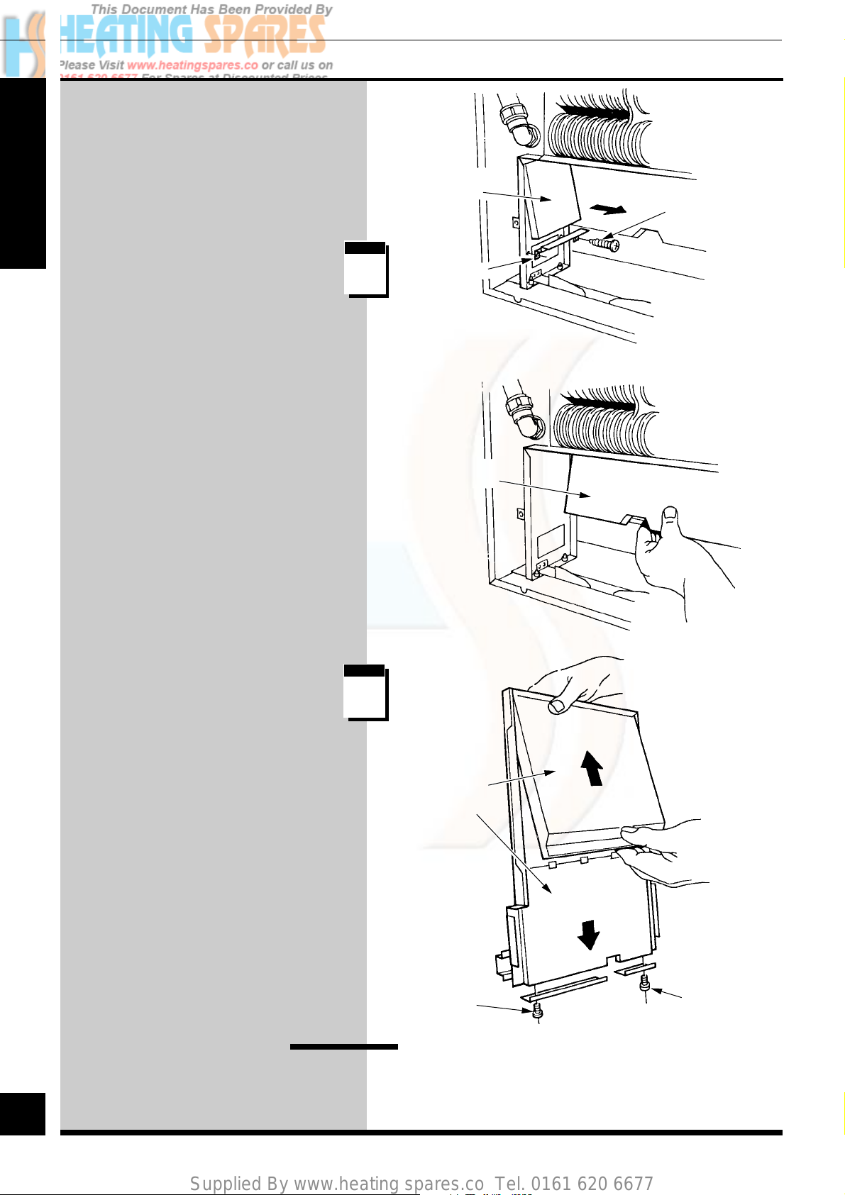
Supplied By www.heating spares.co Tel. 0161 620 6677
12
Replacement of Parts
Insulation
Gain access as Section 10, steps 1 to
10.
SECTION
Combustion Chamber
Sides and Rear:
Remove the baffles.
Remove the insulation and fit the
replacement parts making sure they are
fitted as shown.
COMBUSTION
CHAMBER
SIDE
step
1
COMBUSTION
CHAMBER REAR
3107
SECURING
SCREW (2)
BAFFLE
70 ILLUSTRATED
Heat Exchanger Front
Cover Panel:
Remove panel, Section 10, step 10.
Upper Insulation: push up and pull out
to remove.
Lower insulation: remove the securing
screws and angle and remove the
insulation.
When refitting either, make sure that it
is fitted as shown.
Viewing Window
step
2
COMBUSTION
CHAMBER
FRONT PANELS
SECURING
SCREW (2)
Gain access as Section 10, steps 1 to 4.
SECURING
SCREW (2)
Remove the two screws and then the window.
50
220692C
When replacing take care not to damage the gasket.
50
Page 51

Supplied By www.heating spares.co Tel. 0161 620 6677
Spare Parts
13
Part Identification
The key number in the diagram and the
list will help to identify the part.
Ordering
When ordering any spare parts please
quote the part number and description
from the list together with the model
name and serial number.
If ordering from the local gas
undertaking also quote the GC number of
the appliance and part.
8
7
14
12
5 6B
4760
1
2
10
11
3
SECTION
9
4
6A
13
Key Glow-worm Description GC No.
No Part No
1 800165 Gas valve assembly, inc item11 313 300
2 202539 Thermostat 397 893
3 202538 Overheat thermostat 397 894
4 900817 Printed circuit board 313 301
5 440073 Fan assembly (60) - special 397 987
5 800238 Fan assembly (70) - special 313 397
6A 202135 Air pressure switch - Yamatake 313 303
6B 440165 Air pressure switch - special 313 391
7 203428 Pilot assembly - inc. 8 and 14 313 304
8 800187 Pilot injector - special 313 392
9 205701 Main injector (60) - special 313 393
9 205702 Main injector (70) - special 313 394
10 440108 Control knob - thermostat - assembly 313 306
11 208040 “O” ring - gas valve 334 592
12 202015 Fuse to BS4265 sheet 2. type F1A 334 750
13 WX1800 Ignition lead 313 307
14 800188 Electrode - special 313 395
51
51
220692C
Page 52

Supplied By www.heating spares.co Tel. 0161 620 6677
SECTION
52
Because of our constant endeavour for improvement details may vary slightly from those given in these instructions.
220692C
52
 Loading...