

Page 1
The energy you need
Installation
and User Instructions
Accessories/Flexicom cx
Analogue Timer Kit
18
19
17
20
21
22
23
24
1
2
3
4
5
16
15
14
13
12
11
10
9
8
6
7
0020136593
Page 2
INTRODUCTION
Customer Service:
01773 828100
Technical Helpline:
General and Sales enquiries:
Tel. 01773 824639
Fax: 01773 820569
01773 828300
These instructions consist of, Instructions for Use and Installation Instructions.
The instructions are an integral part of the appliance and must, to comply with the current issue
of the Gas Safety (Installation and Use) Regulations, be handed to the user on completion of
the installation.
Benchmark places responsibilities on both manufacturers and installers. The purpose is to ensure that customers are provided with the correct equipment
for their needs, that it is installed, commissioned and serviced in accordance with the manufacturer’s instructions by a competent person approved at the
time by the Health and Safety Executive and that it meets the requirements of the appropriate Building Regulations. The Benchmark Checklist can be used to
demonstrate compliance with Building Regulations and should be provided to the customer for future reference.
Installers are required to carry out installation, commissioning and servicing work in accordance with the Benchmark Code of Practice which is available
from the Heating and Hotwater Industry Council who manage and promote the Scheme.
Visit www.central heating.co.uk for more information.
18
19
17
20
21
22
23
24
1
2
3
4
16
15
14
13
12
11
10
9
5
8
6
7
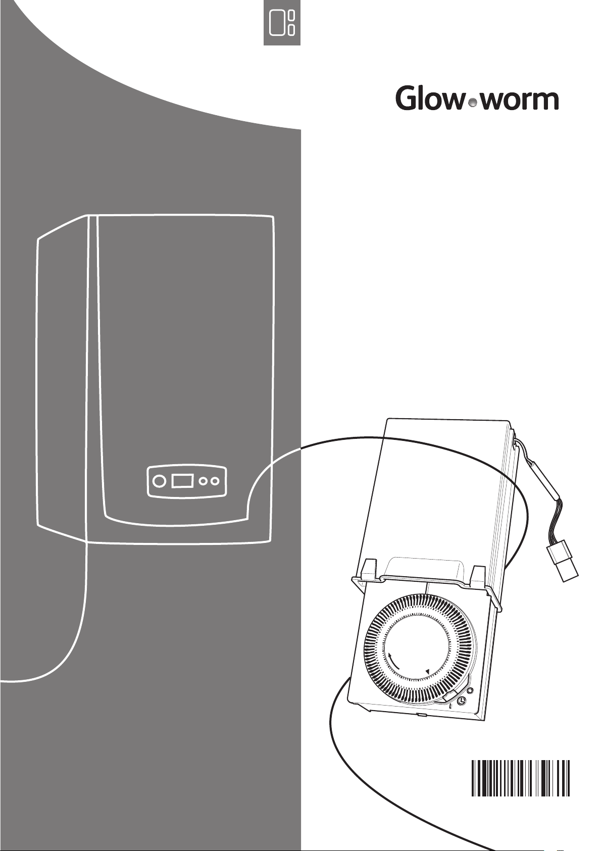
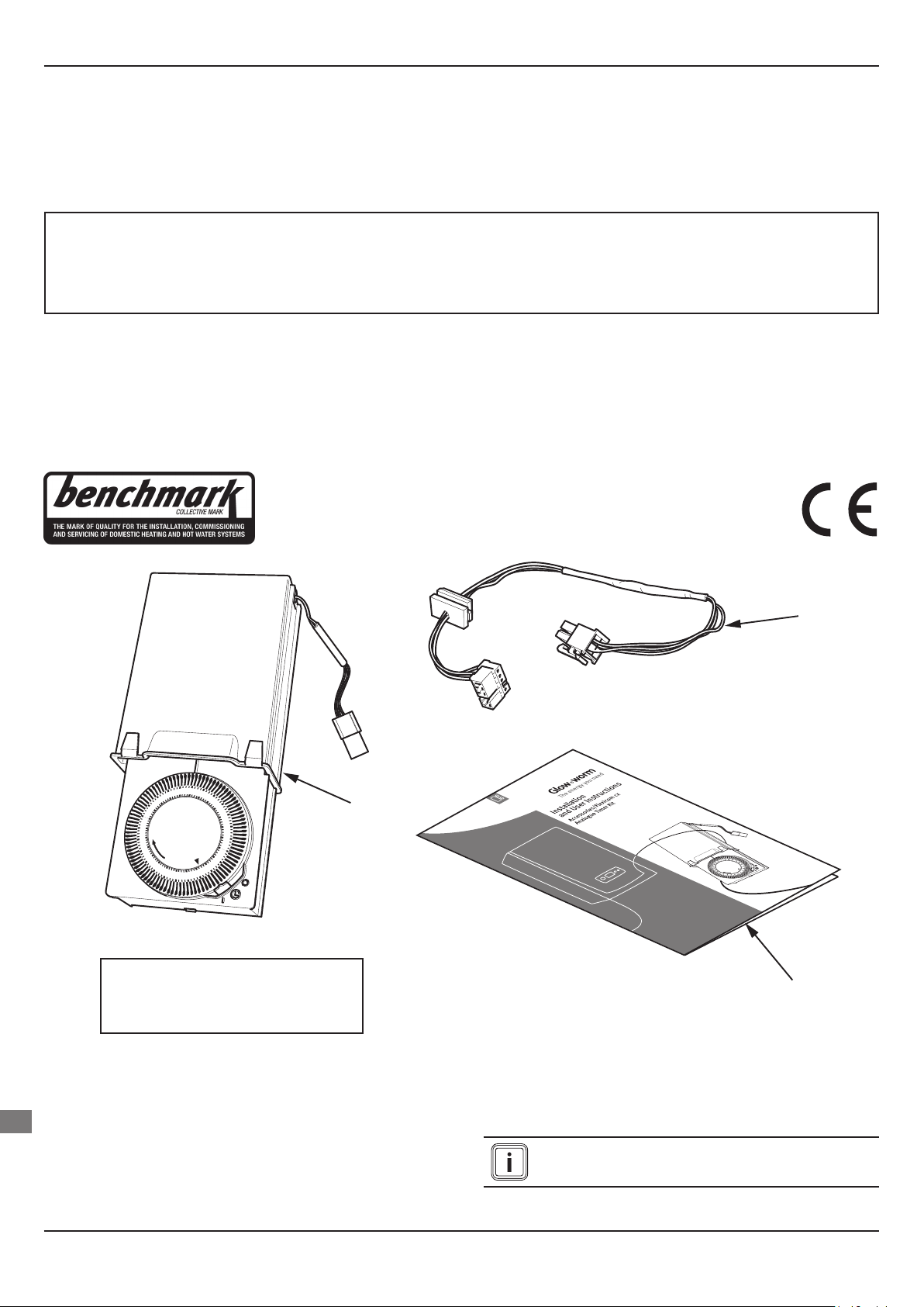
1 - Timer Kit Body
2 - Timer Kit Harness
3 - Installation/User Instructions
2
1
3
CONTENTS OF KIT
These instructions are for the installation and use of the Analogue Timer
Kit, Part No. 0020037830.
EN
These instructions must be read in conjunction with the boiler
instructions.
The electrical installation must be installed by a competent person and in
accordance with the relevant standards.
- 2 -
All wiring to current I.E.E. wiring regulations.
Isolate the boiler from mains power and gas supply.
0020136593 - 01/12 - Glow-worm
Page 3

TIMER
BLANKING
PLATE
use a flat bladed screwdriver here
to remove the blanking plate
TIMER AND
HOUSING
INSTALLATION
1 Fitting the Analogue Timer (to a boiler without timer
housing)
If the boiler does not contain the timer housing,
follow the instructions below.
If the boiler does contain the boiler housing, follow
the instructions detailed in section 2.
1.1 Remove the front casing and hinge down the control
box.
1.2 Remove the timer blanking plate at the bottom of
the boiler by pressing the retaining latches, using an
appropriate tool e.g. a at bladed screwdriver.
Carefully remove the blanking plate.
The timer kit harness and plug are attached to the
blanking plate to aid tting of the timer.
Unplug the harness from the blanking plate by pressing
the retaining catch.
1.3 Fit the plug to the timer kit socket, the plug will only t
one way.
18
19
17
20
21
22
23
24
1
2
3
4
16
15
14
13
12
11
10
9
5
8
6
7
TIMER KIT SOCKET
1.4 Locate the timer kit body into the space left by the
blanking plate on the underside of the boiler.
RETAINING
CATCH
TIMER
BLANKING
PLATE
0020136593 - 01/12 - Glow-worm
TIMER KIT HARNESS
AND PLUG
1.5 Ensure good positioning of the harness then replace
control box and front casing.
1.6 Re-establish mains and gas supply to the boiler.
When using the timer, push the bottom of the timer kit
slide to release it from it’s housing, allow the timer to
fall naturally, it’s movement is controlled by a damper,
do not pull the timer down. To re-engage the timer,
push gently upwards until it clicks into position.
EN
- 3 -
Page 4

USER INSTRUCTIONS
2 Fitting the analogue timer (to a boiler with timer
housing)
If the boiler already contains the timer housing, this
must be removed before tting the timer accessory.
•
Remove front casing and hinge down control box.
• Remove the timer housing and timer harness from the boiler.
• Attach the harness supplied with the timer accessory to the PCB.
• Locate the timer kit body into the space left by the previous timer timer
housing.
• Plug the two harnesses together.
• Ensure good positioning then replace the control box and front casing.
• Re-establish mains and gas supply to the boiler.
3 Timer - Instructions for the User
3.1 Setting the time
Rotate the outer 24hr clock dial and align the arrow to the current time.
Setting the programme “ON and OFF” times.
ON
(Tappets to
the outside)
OFF
(Tappets to
the inside)
24hr
2
3
4
5
6
7
8
9
10
11
12
13
1
24
23
22
21
20
19
18
17
16
14
15
0
I
Clock
Dial
Selector
Switch
Arrow
(indicates
current time)
• Select the ON times by pushing the black tappets to the
outside.
• Select the OFF times by pushing the black tappets to
the inside.
• Position the selector switch to the middle position .
The heating will now operate at your chosen programme.
3.2 To override the timer
Move the selector switch to the I position and the
•
heating will operate continuously.
• Move the selector switch to the 0 position to switch the
heating OFF.
EN
Because of our constant endeavour for improvement, details may vary slightly from those shown in these instructions.
Glow-worm, Nottingham Road, Belper, Derbyshire. DE56 1JT
0020136593 - 01/12 - Glow-worm
- 4 -
 Loading...