

Globalstar SmartOne User Manual

User Manual
Models Included: SmartOneA, SmartOneB, SmartOneBLP
Revision: 1.4

Table of Contents
Addendum..................................................4
SMARTONE Basics...........................................5
Overview..................................................5
Modes of Operation......................................5
Standard Messaging......................................5
Reduced Messaging.......................................6
Theft Recovery..........................................6
Inputs....................................................7
Serial Commands.........................................8
Satellite Communications..................................9
Globalstar Simplex Satellite Network....................9
Getting Started..........................................10
The SMARTONE Device....................................10
Installing Batteries ..................................10
Turning On and Off ................................... 11
Mounting ............................................. 12
Programming Overview ................................. 12
Inputs............................................... 12
Installation of Configuration Software ............... 12
Connecting Devices................................... 13
SMARTONE Configuration Software .........................13
User Data Entry Pane...................................14
Status Pane ............................................ 14
ESN Status Display Table ............................. 14
List ESN(s) Button ................................... 14
View Summary Button .................................. 15
Program Button ....................................... 16
Toolbar ................................................ 16
File Menu ............................................ 16
Tools Menu ........................................... 17
Help Menu ............................................ 20
Getting Started Tab .................................... 20
Standard Messaging Mode without Motion ............... 20
Standard Messaging Mode with Motion .................. 22
Reduced Messaging Mode ............................... 22
Theft Recovery Mode .................................. 22
Standard Messaging Mode without Motion ................. 23
Location Messages Tab ................................ 23
Input Settings Tab ................................... 25
Options Tab .......................................... 27
Standard Messaging Mode with Motion .................... 28
Motion Settings Tab .................................. 28
Location Messages Tab ................................ 29
Input Settings Tab ................................... 30
Options Tab .......................................... 32
Reduced Messaging Mode ................................. 33
Change of Location Area Tab .......................... 33
Inside Change of Location Area ....................... 34
Input Settings Tab ................................... 37
Options Tab .......................................... 38
Theft Recovery Mode .................................... 40
SmartOne Manual Rev 1.4 DOC# 9100-0268-01 p.2

Change of Location Area Tab .......................... 40
Inside Change of Location Area Section ............... 39
Outside Change of Location Area ...................... 42
Input Settings Tab ................................... 42
Options Tab .......................................... 44
Messages................................................. 45
Basic User Information ................................. 45
Global Message Type .................................. 45
Type 0 Message Class ................................ 46
Message Format ....................................... 46
Location Message ..................................... 47
Device Turned On Message ............................. 49
Change of Location Area Alert Message ................ 51
Input Status Changed Message ......................... 53
Undesired Input State Message ........................ 54
Re-Center Message .................................... 56
Type 1 Message Class .................................... 58
Truncated Message .................................... 58
Type 2 Message Class .................................... 59
Raw Message ........................................... 59
Type 3 Message Class .................................... 61
Diagnostic Message ................................... 61
Replace Battery Message .............................. 62
Contact Service Provider Message ..................... 62
Accumulate/Count Message ............................. 64
Messaging Priority ..................................... 65
Prioritization of Periodic Standard Message Report Rates
..................................................... 65
Message Priorities ...................................... 66
Serial Commands ........................................ 66
Serial Packet Format ................................. 66
CRC Algorithm ........................................ 67
Serial Packet Types .................................. 68
Send Truncated Message................................ 68
Send Raw Message...................................... 69
Connecting Serial Devices to The SMARTONE............. 71
Glossary of Terms........................................ 72
Appendix A: Technical Support............................ 75
Appendix B: RF Radiation Exposure Statement.............. 76
Appendix C: Regulatory Notices........................... 77
Appendix D: Environmental Specifications................. 79
Appendix E: Accessories.................................. 80
SMARTONE Old External Inputs Cable - Part #2030-0263-01.. 80
SMARTONE USB Configuration Cable – Part #2030-0261-01.... 80
Appendix F: Battery Installation Guide................... 81
Appendix G: Latitude/Longitude Decoding.................. 82
Appendix H: Standard Message Decoding.................... 83
Appendix I: Diagnostic Message Decoding.................. 84
Appendix J: Accumulate/Count Message Decoding............ 85
Appendix K: Serial Input Cable .......... ............... 86
SmartOne Manual Rev 1.4 DOC# 9100-0268-01 p.3

Addendum
I. A new version, SmartOne LP, is available. This version can be
powered by line power or batteries. It can be supplied line power with
the External Inputs Cable or the Serial Input Cable.
Specifications:
A. Input Voltage- The SmartOne LP will operate on 10 to 48 Volts DC.
B. Switching- If batteries are installed, the unit will automatically
switch to battery power if line power input is lost.
C. Connection Method-
1. When using the Serial Input Cable, connect the voltage supply
positive(+) to the VIOLET wire through a 1 Ampere Fuse. The fuse
should be placed within 1 foot (30cm) of the voltage source. Connect
the negative(-) source to the GRAY wire. Always use crimp connectors
or solder the wires and cover the connection with shrink tubing.
II. A new accessory, the Serial Input Cable, is available. This cable
simplifies the sending of serial data (see page 66). In addition, it
supplies access to the Dry Contact Inputs and the Line Power inputs.
SmartOne Manual Rev 1.4 DOC# 9100-0268-01 p.4

SMARTONE Basics
Overview
The SMARTONE is designed to track the position of Trailers, Cargo
Containers, Heavy Construction Equipment, Generators, Boats/Barges and any
other mobile assets. The SMARTONE also has 2 inputs to manage run time of
engines and/or other alarm inputs.
The SMARTONE processes GPS satellite signals to obtain its position in
terms of longitude and latitude and transmits this information over
Globalstar’s Simplex Satellite Network. In addition to position
information, the SMARTONE transmits other message types that include
battery status, input alarm status and diagnostic information. The
SMARTONE is configured using a computer and connection cable to
communicate these messages at certain times and/or under certain
conditions.
Modes of Operation
The SMARTONE can be configured to operate in three different Modes:
Standard Messaging Mode, Reduced Messaging Mode and Theft Recovery Mode.
Standard Messaging
In Standard Messaging Mode, the SMARTONE reports its position at regular time
intervals that are programmed during the configuration process. Standard
Messaging Mode can also be configured to utilize the SMARTONE’s internal
vibration sensor. If enabled, the SMARTONE will transmit its position at
independently configured regular time intervals when the device is In Motion.
Location messages can be programmed to be constant (Message Interval) or the
device may be configured to use up to 12 different delays in
sequence (Message-Time(s) of Day). Message Interval can be programmed
in 1 minute intervals from 35 minutes up to 45 days.
Example of Message Interval: The SMARTONE is configured to
report once every 24 hours when not in motion and every 2 hours when
In Motion. If the SMARTONE went into motion at any time of day the
Message Interval while In Motion would be every 2 hours beginning
when the SMARTONE started moving.
Example of Message-Time(s) of Day: The SMARTONE is configured
with a message time of day of 9:00am, a second message time of
day of 12:00 noon, a third message time of day of 8:00pm and
once per hour when In Motion. The SMARTONE would transmit 3
messages a day at the same configured times every day. If the
SMARTONE went In Motion it would transmit its location message
every hour.
SmartOne Manual Rev 1.4 DOC# 9100-0268-01 p.5

Usage Example: A Company is required to report the GPS locations
of their hazardous chemical containers twice a day. Based on
this requirement the Company has 2 options: set a message interval of
every 12 hours, the 12 hour internal begins when the device is
powered up or configure message times of day 12:00 noon and 12:00
midnight.
Reduced Messaging
Reduced Messaging Mode reduces the cost associated with transmitting
messages over Globalstar’s network by sending messages at a minimal
message interval when the asset is in a defined area and transmitting at
a higher message interval when the asset is changing locations. These
message intervals are set as part of the configuration process based on
the concept that repeated reporting information of the same location
when an asset has not moved from its defined area is redundant and
doesn’t provide addition usable information about its current location.
By comparing current and prior position information, the SMARTONE
determines if its location is changing. The definable area in which the
device should remain in Reduced Messaging Mode is called the Change of
Location Area and it is a square. When the SMARTONE goes outside of the
square, its location is considered to be changing or relocating.
Usage Example: A fleet operator owns 1,000 trailers. When the
trailer(s) are sitting at a depot they want a location message
once a day. They also want a message notification within 1 hour
when a trailer has left a depot. Lastly, they want a location
message every 3 hours when a trailer is moving between depots.
Based on this requirement, the fleet operator will need to set
the Change of Location Area (size of the depots where the
trailers will visit), the message interval while the trailers
are inside the Change of Location Area (1 per day), the interval
at which the SMARTONE will check its location while in a State
of Vibration and inside the Change of Location Area(1 per hour),
set the number of messages when the trailer leaves the Change of
Location Area (1 Change of Location Area Alert Message) and the
message interval while the trailers are in transit between
depots (every 3 hours).
Theft Recovery
When the SMARTONE is configured to operate in the Theft Recovery Mode,
it differentiates between authorized and unauthorized movement of an
asset. While the power to the SMARTONE is turned off, all movement of
the asset is considered authorized. When power is turned on, the
SMARTONE obtains a position from GPS satellite signals. The position is
used to set the center of the defined Change of Location Area in Theft
Recovery Mode. While in the Change of Location Area, the SMARTONE
obtains position fixes at an interval set during configuration. As long
as the SMARTONE remains within the Change of Location Area all movement
is considered to be authorized.
SmartOne Manual Rev 1.4 DOC# 9100-0268-01 p.6
Once the SMARTONE’s position is outside of the Change of Location Area,
it alerts the SMARTONE to an unauthorized movement and immediately sends
a location message (Change of Location Alert Message). The SMARTONE
then continues to send location messages at a message interval set
during the configuration process until the power is turned off or the
battery is dead.
Usage Example: A construction company is working on a job site
for 1 year and wants to make sure that the generators and other
heavy equipment on site are not stolen. The company wants to
check the location of their equipment 12 times a day, every 2
hours, to confirm the asset hasn’t been stolen but only wants a
transmitted location message once per day. Based on this
requirement, the construction company will need to set the
Change of Location Area (size of the job site), the message
interval while inside the Change of Location Area (1 per day),
the interval at which the SMARTONE will check its location while
in a State of Vibration and within the Change of Location Area
(every 2 hours) and the message interval if the asset is outside
the Change of Location Area (stolen).
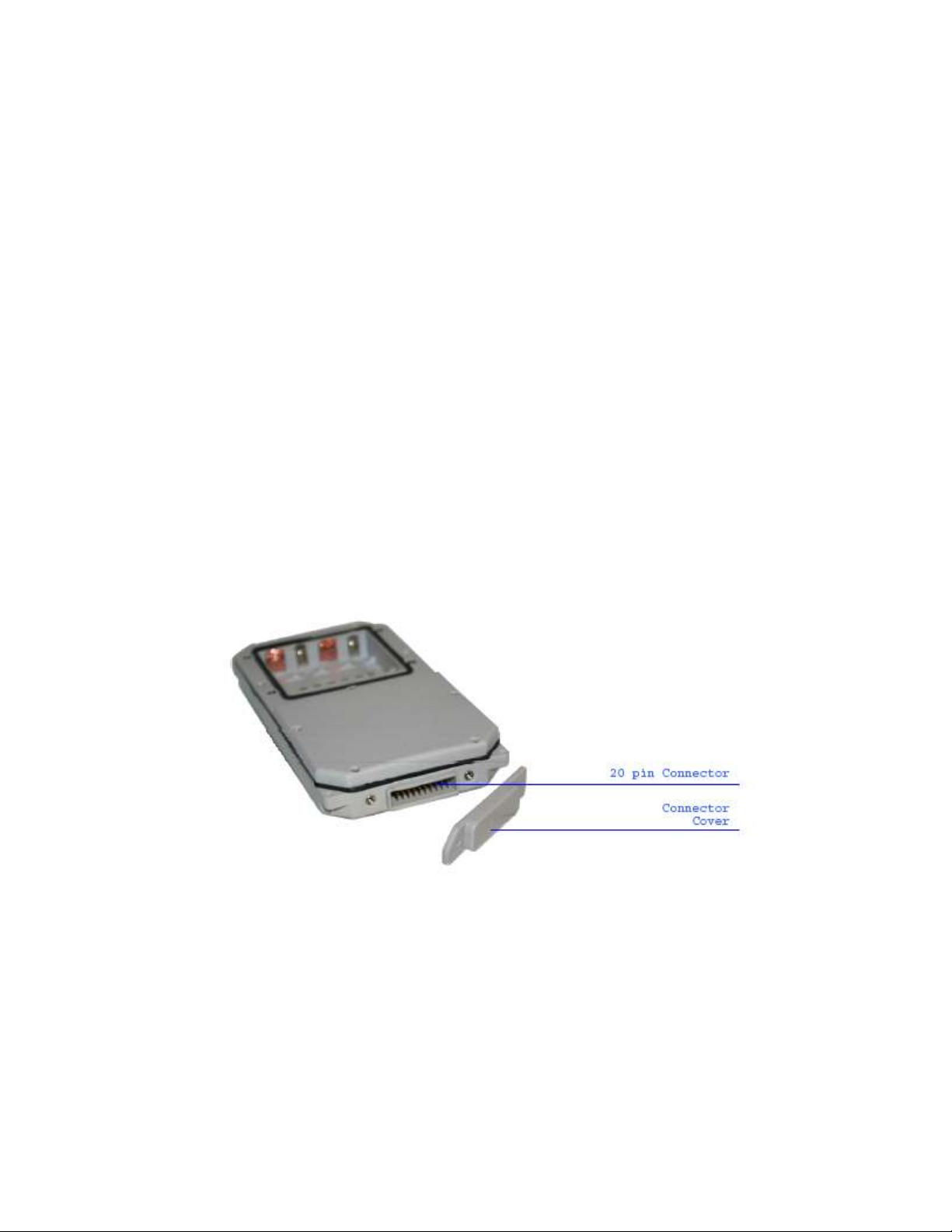
Inputs
The SMARTONE has a 20 pin connector that provides ground, two dry
contact inputs and a power switch input.
The SMARTONE allows sending Input Status Changed Messages for both Input
1 and Input 2. The Inputs must be asserted for at least 5 seconds in
order to be acknowledged.
Usage Example: A construction company needs to document, per
their contract with the City, when they begin their work day and
when they end their work day. Based on this requirement, the
SMARTONE would be connected to the ignition switch and
configured to send a transmission with location when the input
changes state.
SmartOne Manual Rev 1.4 DOC# 9100-0268-01 p.7

The SMARTONE also allows the user to define the Message Interval while
the Inputs are in an Undesired State, either Opened or Closed.
Usage Example: A company has remote containers at job sites and
would like to know if a door is ajar. If a door is left ajar
the company would like a notification every 2 hours. Based on
this requirement, the SMARTONE would be connected to an open
door sensor with the Undesired Input State Message enabled and
set as Opened with a Message Interval of 2 hours.
Note: The SMARTONE uses a 5 minute "hysteresis" window to prevent sending
false alarms. This means that only one status change message can be sent
during any 5 minute time window. Any subsequent status changes will be
detected but not reported. Multiple status changes during any 5 minute window
will result in the transmission of incorrect trigger bits. Refer to page 52
for "Input Status Changed Message".
The SMARTONE has the ability to send an Accumulate/Count Message at a
regular configurable interval and/or based on configurable multiples of
accumulated hours and/or number of counted events or hours of vibration.
Usage Example 1: A construction company needs weekly engine run
times for their heavy equipment to manage their maintenance
scheduling. Based on this requirement, the company would
schedule a weekly Accumulate/Count Message.
Usage Example 2: A construction company wants to insure that no
equipment is ever operated beyond 400 hours without maintenance.
Based on this requirement, the company would schedule an
Accumulate/Count Message for every 400 hours of use.
The SMARTONE has the ability to send both Status Change and Undesired State
messages based on vibration.
Serial Commands
The SMARTONE uses the I/O port for unit configuration as well as interface to
remote passive and smart sensors. Two commands are provided in the unit
interface to support smart sensors. External sensors or instruments that can
format and communicate to the SMARTONE can send user data through the
SMARTONE by using these two commands.
The SMARTONE connects to smart sensors via the SMARTONE Serial Cable.
Spot offers 2 accessory cables for the SMARTONE, the USB Configuration
Cable and the Serial Cable. See Appendix E: Accessories.
SmartOne Manual Rev 1.4 DOC# 9100-0268-01 p.8
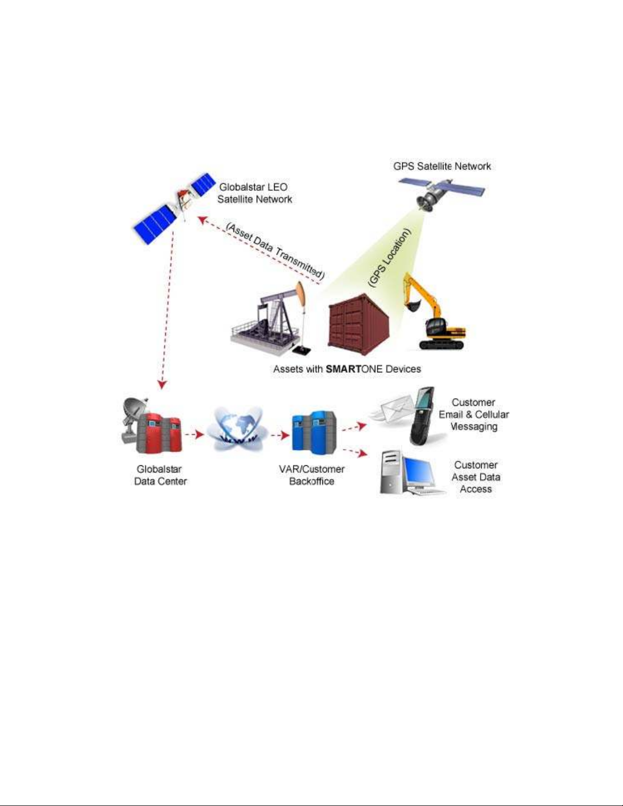
Satellite Communications
The SMARTONE communicates with both the GPS satellite Network and the
Globalstar Simplex Satellite Network. All GPS locations are pulled from
the GPS network and all transmissions are sent via the Globalstar
Simplex Satellite Network.
The SMARTONE has the unique ability to check its GPS Coordinates at a
programmable rate while it is inside of the Change of Location Area
without actually sending a message over the Globalstar Simplex Satellite
Network.
For a Location Message, the SMARTONE will wake up at a scheduled
interval or time of day and begins to acquire a GPS fix. Once it
receives its GPS fix, it will transmit the location to the Globalstar
Simplex Satellite Network.
Globalstar Simplex Satellite Network
The network consists of 40+ Low Earth Orbiting (LEO) satellites that are
constantly orbiting the earth and complete their orbits in less than 2
hours. Because of this, the SMARTONE will be in contact with at least
one of the satellites during each scheduled transmission. In LEO
communication networks the satellites are constantly changing their
positions in the sky relative to the transmitter on earth. This
minimized the shading effects seen in geostationary satellite systems
SmartOne Manual Rev 1.4 DOC# 9100-0268-01 p.9
where the mobile device must be pointed toward a specific direction in
the sky. Geostationary satellites also orbit at a much higher altitude
and move along the equator.
Messages are transmitted from the SMARTONE via the Globalstar Simplex
Satellite Network using an uplink-only connection (one-way data
transmission) and received by a Globalstar Simplex Ground Station. The
messages are then sent via an HTTP or FTP server to the internet and
received by the VAR or end customer’s back office application and
converted into actionable data.
The SMARTONE will send each message 3 times to insure that the message
has been received by the Globalstar Satellite Constellation. Once
Globalstar receives the message, any remaining duplicate messages are
ignored and discarded (VAR or end user account is only charged for 1
transmission).
Getting Started
The SMARTONE Device
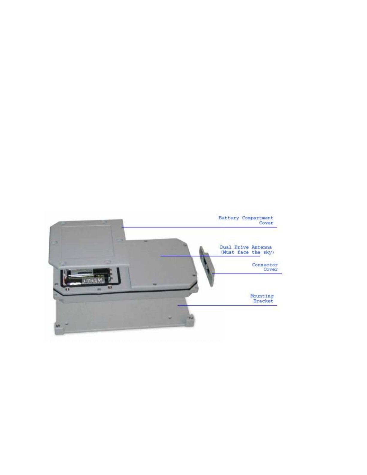
Installing Batteries
The SMARTONE is powered by four 1.5v Lithium ‘AA’ batteries. The battery
compartment is accessible from the top of the device by removing the six
slotted screws. Remove the water-tight cover and insert the batteries
as indicated.
*When the batteries are removed and replaced the device will retain its
configuration.
SmartOne Manual Rev 1.4 DOC# 9100-0268-01 p.10
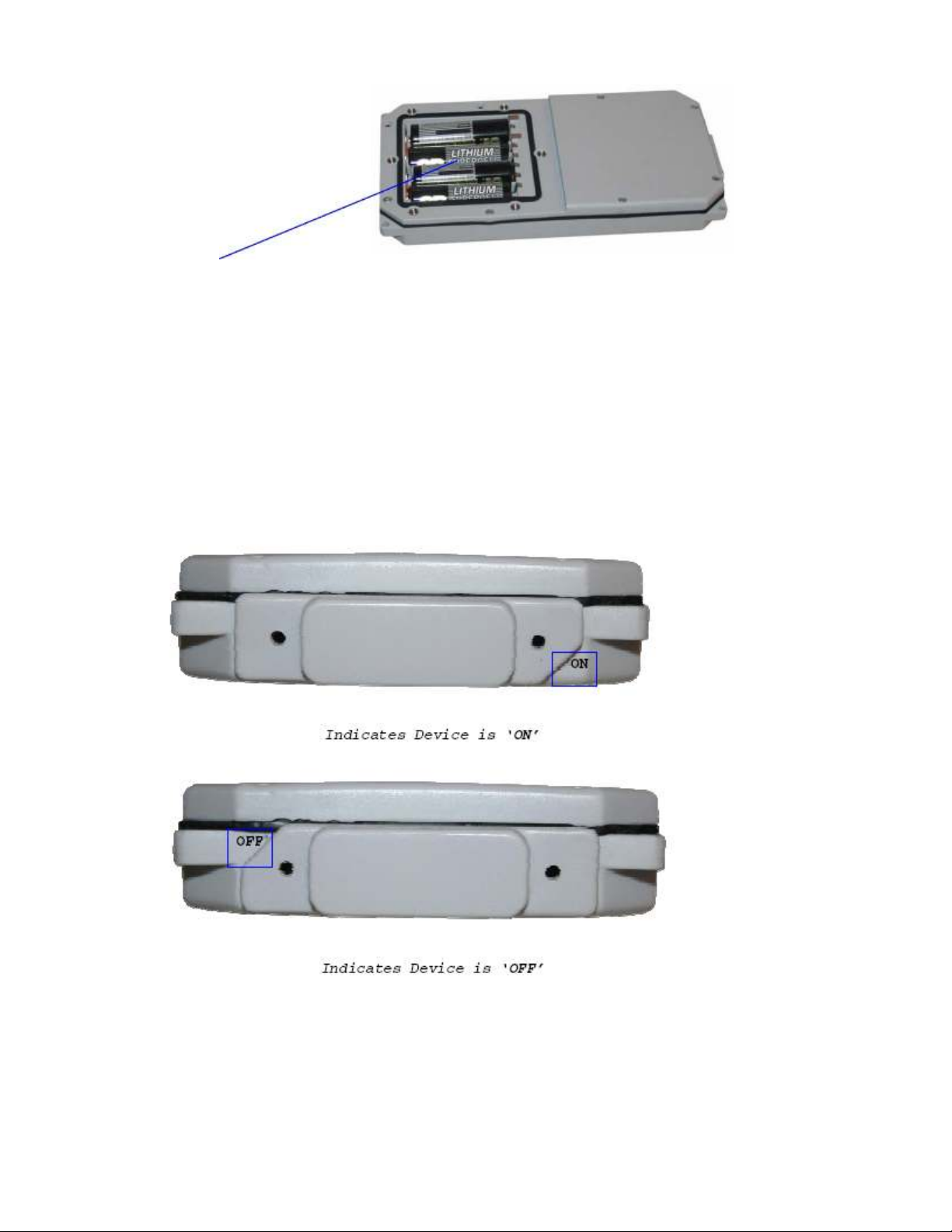
Battery Placement
Turning On and Off
To turn the device ‘On’ or ‘Off’, remove the connector cover from the
end of the device. Then invert and replace the connector cover so that
the word ‘Off’ or ‘On’, whichever is desired is visible.
*See Appendix F – Battery Installation Guide for further information on
how the connector cover should engage with the SMARTONE.
SmartOne Manual Rev 1.4 DOC# 9100-0268-01 p.11
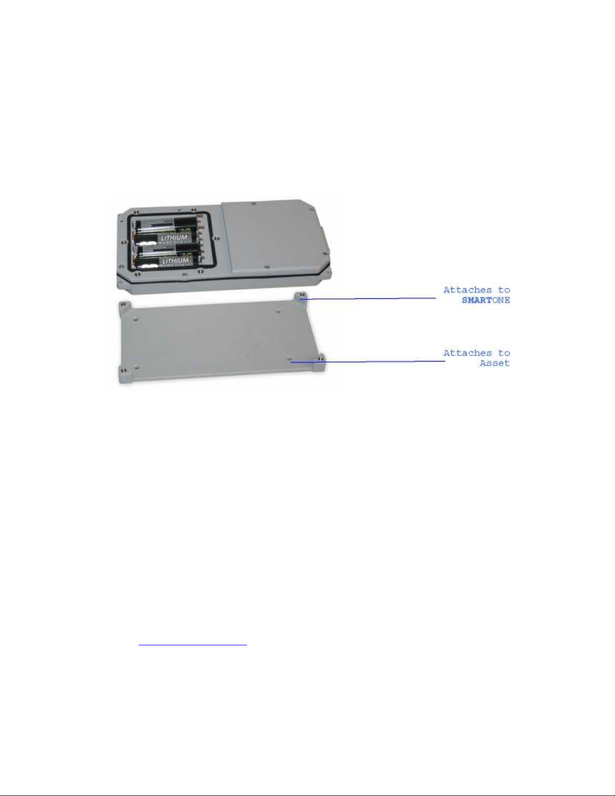
Mounting
The SMARTONE is designed to be mounted to an asset using double-sided
adhesive tape and/or the included mounting bracket. The mounting bracket
has four screws that attach to the asset and allows the SMARTONE to be
mounted so the antenna can face the sky whether mounted internally or
externally. This enables the antenna to have a direct view of the sky
with mounting flexibility. The SMARTONE attaches to the mounting
bracket using four Phillips-head screws.
Programming Overview
The SMARTONE comes ready to use with a factory configuration loaded in
the device. The factory configuration, Standard Messaging without Motion
and Interval Messaging of 12 hours, may be changed using the SMARTONE
Configuration Software, the USB Configuration Cable and a PC.
Inputs
The SMARTONE has two inputs that can be accessed by using the SMARTONE
Input Cable, which is sold as an accessory to the device.
Installation of Configuration Software
The SMARTONE Configuration Software can be downloaded from the Spot
website at www.globalstar.com. Log-in to your VAR account using your username
and password. The Configuration Software is located in the software
downloads section and is supported by Windows 7, Windows Vista, Windows XP
Service Pack 2, Windows 2000 and Windows 98.
SmartOne Manual Rev 1.4 DOC# 9100-0268-01 p.12
Connecting Devices
The SMARTONE, with batteries installed and battery cover screwed down,
connects to a PC using a USB Configuration Cable. The SMARTONE
Configuration Software may be used without being connected to devices to
prepare configurations, but must be connected to a device using the USB
Configuration Cable to Program. Once the Program button has been
depressed the Configuration Cable should not be disconnected, if already
connected, from the device and/or the computer. The USB Configuration
Cable plugs into the SMARTONE when the connector cover is removed.
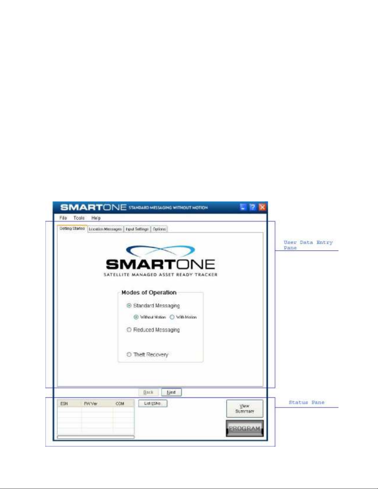
SMARTONE Configuration Software
Once installed on a PC, the SMARTONE Configuration Software is used to
configure SMARTONE's. The configuration has a tab-based, context-switched
user data entry pane on the top screen of the window and a static status
pane on the bottom.
SmartOne Manual Rev 1.4 DOC# 9100-0268-01 p.13
User Data Entry Pane
The user data entry pane contains a context-switched user entry area for
displaying and inputting configuration data. The information is
organized in pages with page manipulation provided through tabs along
the top of the pane. Selecting a tab will change the context of the
upper pane. The tabs are named to group similar functions on the same
page. The tabs will change according to the operation Mode selected.
The Back and Next buttons allow the user to move from tab to tab without
clicking on the tab name.
Status Pane
The Status Pane contains a table with a list of devices connected to the
PC, their ESN(s), firmware version and COMM port assigned to each device
as well as the execution buttons for configuring connected SMARTONE(s).
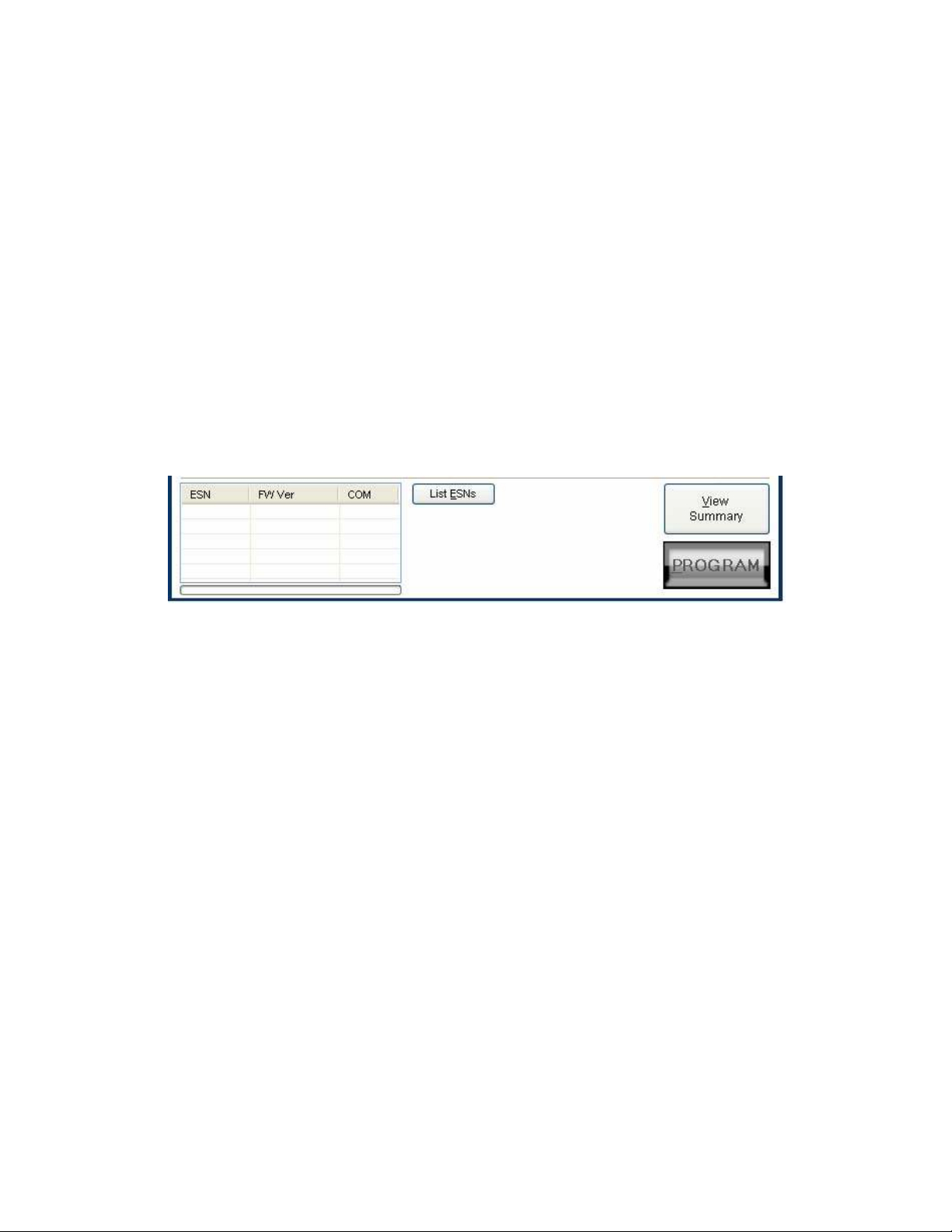
ESN Status Display Table
ESN Column - This column displays a list of the Electronic Serial
Numbers for SMARTONE(s) connected to the PC.
FW Ver Column - This column displays a list of firmware version for the
main processor for each SMARTONE in the list.
COM Column - This column displays a list of the assigned serial
communication ports for each SMARTONE.
List ESN(s) Button
This button shall cause the Configuration Software to search for any
valid devices that are connected to the PC.
A pop up window informs the user that the program is searching for
devices connected to the computer while this search is being performed.
SmartOne Manual Rev 1.4 DOC# 9100-0268-01 p.14

View Summary Button
This button causes the Configuration Software to open a separate window,
which contains plain text readout of every user configurable parameter
that exists for the SMARTONE.
View Summary Window
The Menu Bar in the View Summary Window allows the user to either print
the parameters or save the configuration parameters to a text file. This
window remains open while the user manipulates the fields in the User
Data Entry Pane tabs and will update as changes are made.
SmartOne Manual Rev 1.4 DOC# 9100-0268-01 p.15
Program Button
The PROGRAM button in the Status Pane is used to send the data in the
Configuration Software to the connected SMARTONE (s). The SMARTONE will
be updated with the data from the Configuration Software.
The user is queried to confirm device program before execution of the
function.
File Menu in the View Summary Window allows the user to either save the
configuration to file or print configuration.
Toolbar
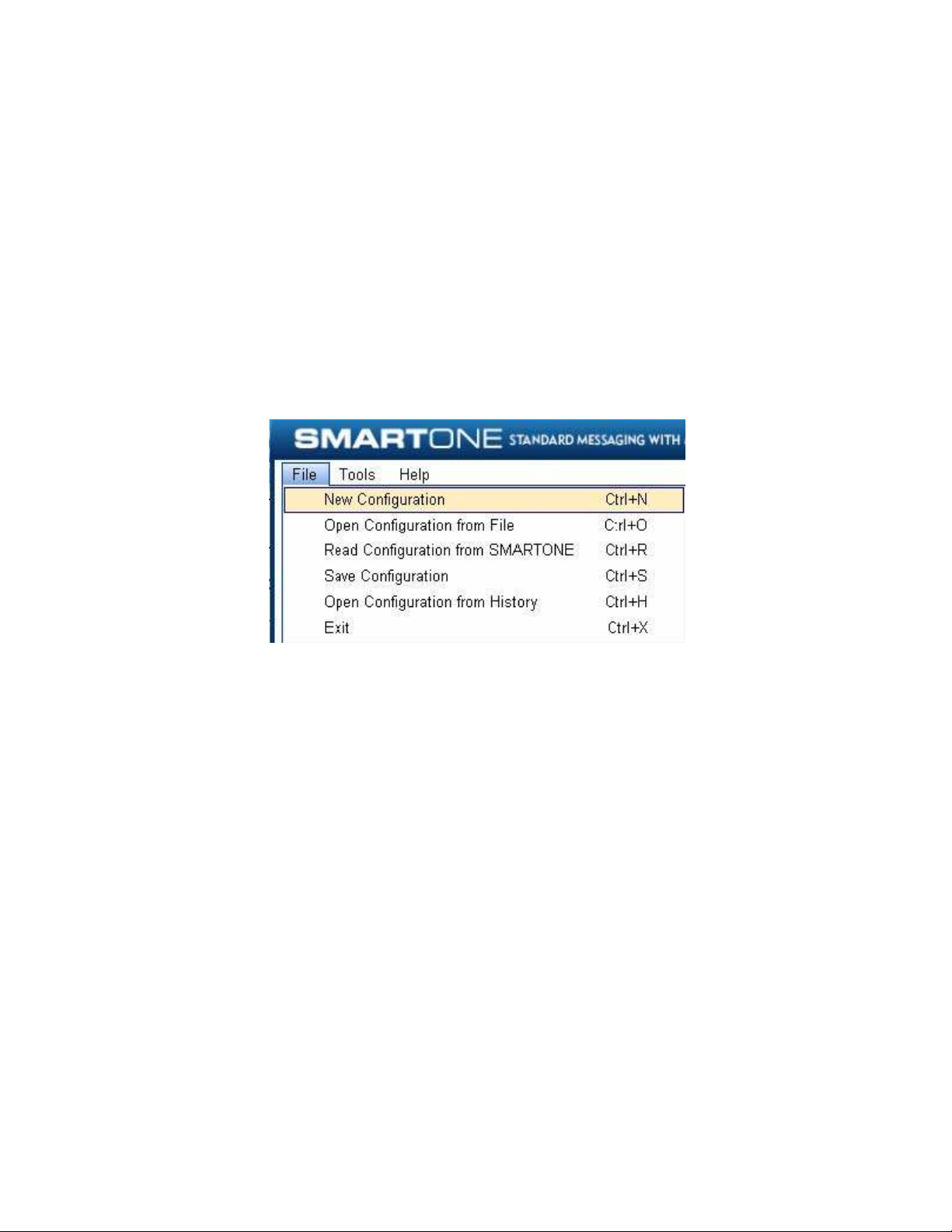
File Menu
New Configuration. This will reset the values for all configurable
parameters to default. Standard Messaging without Motion with a
transmission every 12 hours is the default Mode of operation.
This selection will open a prompt window asking for confirmation to
restore all settings to their default. This will not affect the settings
stored inside the connected SMARTONE(s). The settings will only reset in
the software display, not in any device(s) connected to the PC unless
the PROGRAM button is clicked to download configuration to the device.
Open Configuration from File. This opens a window that allows the user
to browse for a valid configuration file that has previously been saved.
Selecting a file will cause all of the settings contained in the file to
be loaded into the software display only, not in any devices connected
to the PC. Click the PROGRAM button to download configuration to the
device.
Read Configuration from SMARTONE. This will query all of the
configurable parameters saved in a device connected to the PC. The
values for each configurable parameter in the device will be displayed
in the User Data Entry Pane.
SmartOne Manual Rev 1.4 DOC# 9100-0268-01 p.16
Save Configuration. This will open a window that allows the user to
browse to a location and save all of the configuration settings to two
separate files:
The configuration file. This file is non-editable.
A text file. An ASCII format file that contains each parameter and
parameter value in a standard delimited format.
Open Configuration from History. Every time a device is successfully
programmed, the configuration will save that occurrence to a text log
file. The information stored is the ESN of the device, the local time
at which it was programmed and the actual configuration of the device.
When selected, a window opens where the user can sort by ESN or
date/time of programming and select a configuration. This loads the
selected configuration settings into the User Data Entry Pane, but not
into any device(s) connected to the PC.
Exit. This causes the program to close.
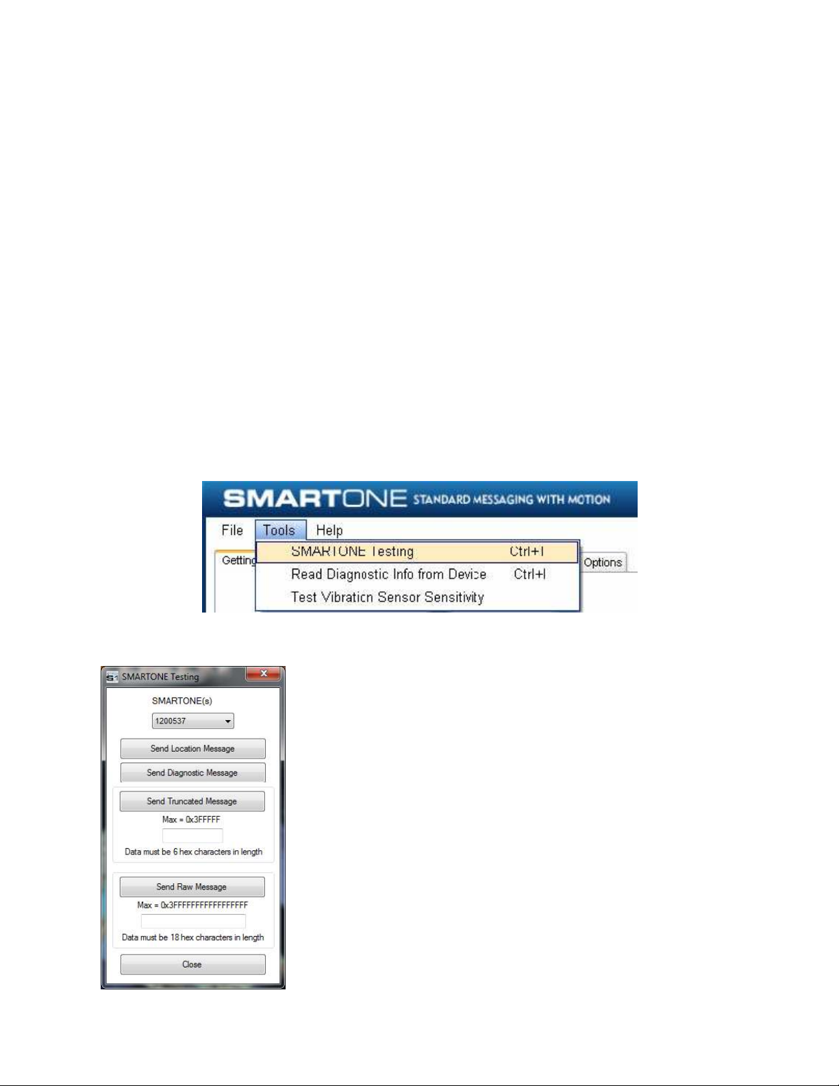
Tools Menu
SMARTONE Testing. This command opens up a window with the following
options:
SmartOne Manual Rev 1.4 DOC# 9100-0268-01 p.17

Send Location Message - causes the SMARTONE connected to the
COM port to obtain a GPS fix and send a Location Message.
Send Diagnostic Message – causes the SMARTONE connected to
send diagnostic information including battery status, GPS
average search time, GPS fails and number of transmissions
since last diagnostic message.
Send Data w/GPS Message - causes the SMARTONE to seek a GPS
location, and then send a Truncated SMARTONE message (type 1).
The hex-character data in the text box below the command will be
appended to the GPS data and sent.
Send Data w/o GPS message - causes the SMARTONE to send the first
8 bytes of data in the text box above the command as the payload
for the Raw Payload Message (type 2). The hex-character data in
the text box above the command will be sent instead of the normal
SMARTONE position data.
Close – causes the pop up window to close.
Read Diagnostic Information from Device. This command line causes the
Configuration Software to query the diagnostic information from the
SMARTONE and display the information in a pop up window in a text
format.
SmartOne Manual Rev 1.4 DOC# 9100-0268-01 p.18
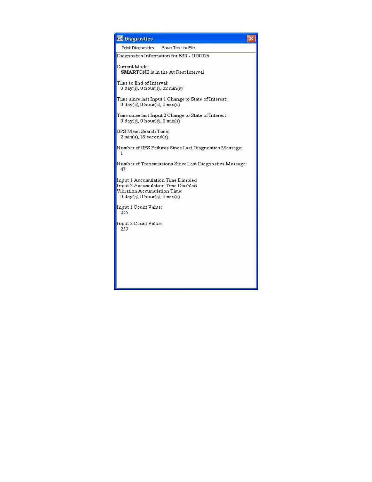
There are two menu options available in the pop up window:
Print Diagnostic –prints the diagnostic information.
Save Text to File – Opens a window, which allows the user to browse
for a location and save the diagnostic information in a text file.
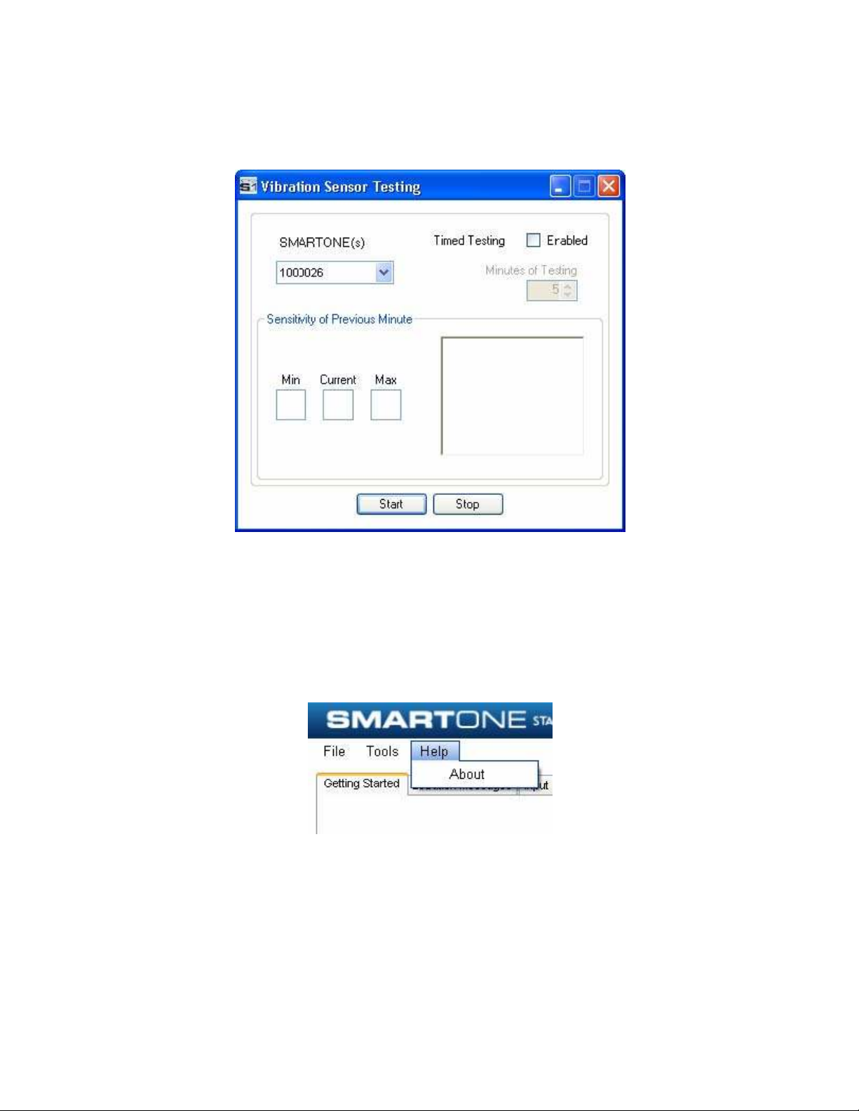
Test Vibration Sensor Button is used to find the minimum, maximum and
average vibration sensitivity detected by the sensor. This information
helps to determine the appropriate Level of Sensitivity for the
vibration sensor. This window will update real time while connected to
the SMARTONE.
SmartOne Manual Rev 1.4 DOC# 9100-0268-01 p.19
Help Menu
About. This pops up a window with the SMARTONE Configuration version
number.
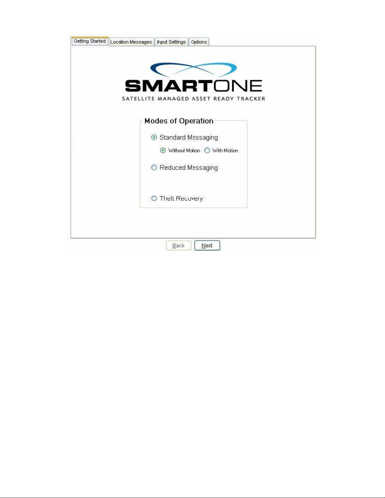
Getting Started Tab
The Getting Started Tab allows the user to select the Mode of operation
for the SMARTONE. The Modes include Standard Messaging with or without
motion, Reduced Messaging and Theft Recovery Mode.
SmartOne Manual Rev 1.4 DOC# 9100-0268-01 p.20
Standard Messaging Mode without Motion
The Standard Messaging without Motion Mode is selected for basic
tracking functionality on the SMARTONE. The SMARTONE will automatically
report its position at regular time intervals. The messages sent in this
Mode are called Location Messages. These messages include the GPS
coordinates of the actual location of the SMARTONE.
In this Mode, the vibration sensor is OFF.
SmartOne Manual Rev 1.4 DOC# 9100-0268-01 p.21

Standard Messaging Mode with Motion
The Standard Messaging with Motion Mode is selected for basic tracking
functionality with motion detection capabilities. The user defines the
motion parameters for each application including the Level of
Sensitivity of the vibration sensor, Time to be in a State of Vibration
and Time to be in a State of Lacking Vibration. The SMARTONE can be set
to report at a different rate, Message Interval while In Motion,
compared to the Location Message Interval.
Reduced Messaging Mode
The Reduced Messaging Mode is ideal for asset management with reduced
messaging capability of the SMARTONE. The SMARTONE creates a Change of
Location Area of configurable size around the device. If the SMARTONE
stays within its Change of Location Area, the number of transmissions
will be reduced.
When the SMARTONE leaves the Change of Location Area and returned to a
State of Lacking Vibration a new Change of Location Area is created
around the SMARTONE.
Theft Recovery Mode
The Theft Recovery Mode is ideal for assets that are high-risk for
theft. In this Mode, the SMARTONE creates a Change of Location Area
around its location when powered. The size of the Change of Location
Area is a configurable parameter equal to the distance the device must
move to be considered outside the Change of Location Area. If outside
the Change of Location Area, the SMARTONE goes into recovery Mode,
transmitting frequent messages until the asset is recovered. The message
interval in recovery Mode is a configurable parameter; however, the
default value is 10 minutes.
SmartOne Manual Rev 1.4 DOC# 9100-0268-01 p.22
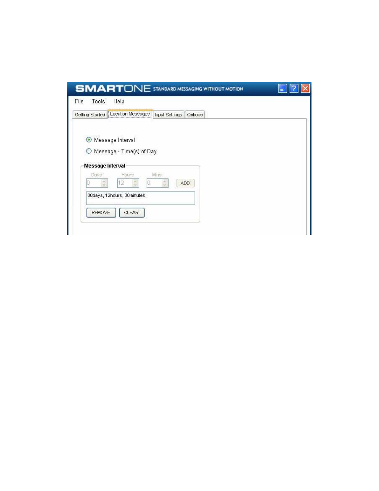
Standard Messaging Mode without Motion
Location Messages Tab
Message Interval. The SMARTONE can be configured to report at a specific
message interval specified by days, hours and minutes. The SMARTONE
accepts a single interval only.
Once the interval has been entered in Days, Hours, and Minutes, click
the ADD button to accept the interval and add it to the message interval
box.
Message – Time(s) of Day. The SMARTONE can be configured to report at
specific time(s) of day. The message interval box allows up to 12 times
of day to send Location Messages.
SmartOne Manual Rev 1.4 DOC# 9100-0268-01 p.23
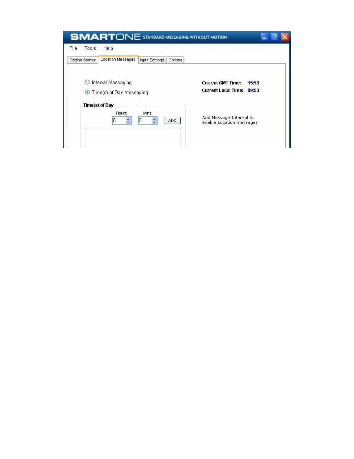
The REMOVE button deletes the selected time of day or interval from the
message interval box. The CLEAR button deletes all the time of days or
interval in the message interval box.
SmartOne Manual Rev 1.4 DOC# 9100-0268-01 p.24
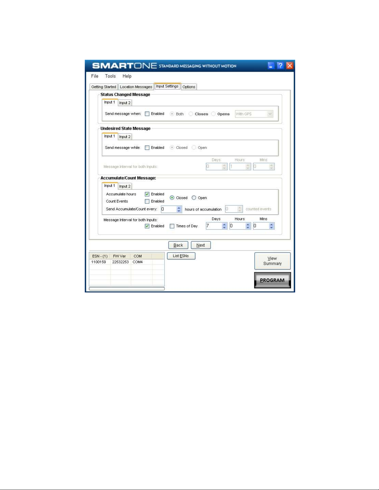
Input Settings Tab
Status Changed Message. The SMARTONE has two inputs that can be
configured to send a Status Changed Message once the selected input
opens, closes, or in both events. The Message sent can or cannot contain
the GPS coordinates of the device at the time the status of the input(s)
changed.
Undesired State Message. The SMARTONE can be configured to send messages
throughout the time the input is in the desired state, either to opened
or closed position. The message interval while the input is active can
be configured in Days, Hours, and Minutes. Once the input is de
activated, the SMARTONE will return to the message interval or time (s)
of day for Location Messages.
Accumulate/Count Message: The SMARTONE can accumulate hours and events
while input 1 or input 2 is enabled. The SMARTONE can send an
accumulate/count message once the configurable intervals specified in
days, hours, and minutes. If Times of Day is selected, user will specify
SmartOne Manual Rev 1.4 DOC# 9100-0268-01 p.25
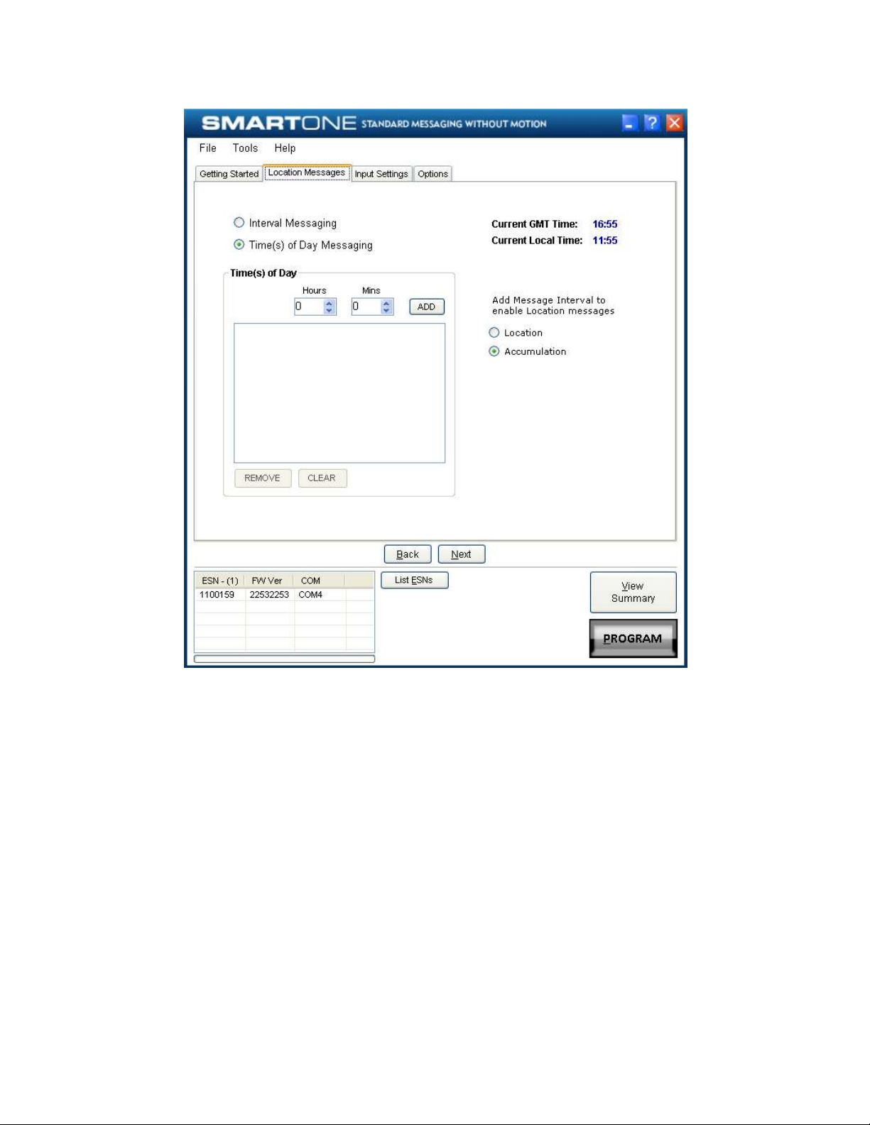
the times in the Location Message Tab.
SmartOne Manual Rev 1.4 DOC# 9100-0268-01 p.26
 Loading...