

Globalstar GIK-1700 Installation Guide
Installation Sheet for the QUALCOMM Globalstar GIK-1700 Globalstar Installation Kit
1 Precautions for installation
1. This kit should be professionally installed.
2. Turn off the ignition and disconnect the vehicle’s battery terminal while installing the kit.
3. Mount the Globalstar Installation Kit (GIK) so it does not interfere with normal driving
operations and is not exposed to hot air from the vehicle’s heater.
4. Do not install the kit directly over any type of electrical or connecting wire or pipeline for fuel, oil,
or air conditioning.
5. Do not place objects in the area over the air bag or in the air bag deployment area. Serious injury
could result.
6. The kit is designed for vehicles with a negative ground 12 volt electrical system only. Other supply
voltages or polarities could damage the equipment.
7. Use only the cables included in the kit to connect the exterior antenna to the kit, and only the
supplied fuses for wiring.
8. After installation, check that the antenna ca ble and external antenna cable do not interfere with
the operation of the car in any way. Make sure all of the cables operate properly.
9. After installation, make sure that all the component s are secured and do not shift when the
vehicle is moving or stopped.
When connecting the leads on the antenna cable:
1. Make sure you do not drill through anything under the car.
2. Connect the red and then the yellow power input leads only after all other leads are connected.
3. Make firm connections.
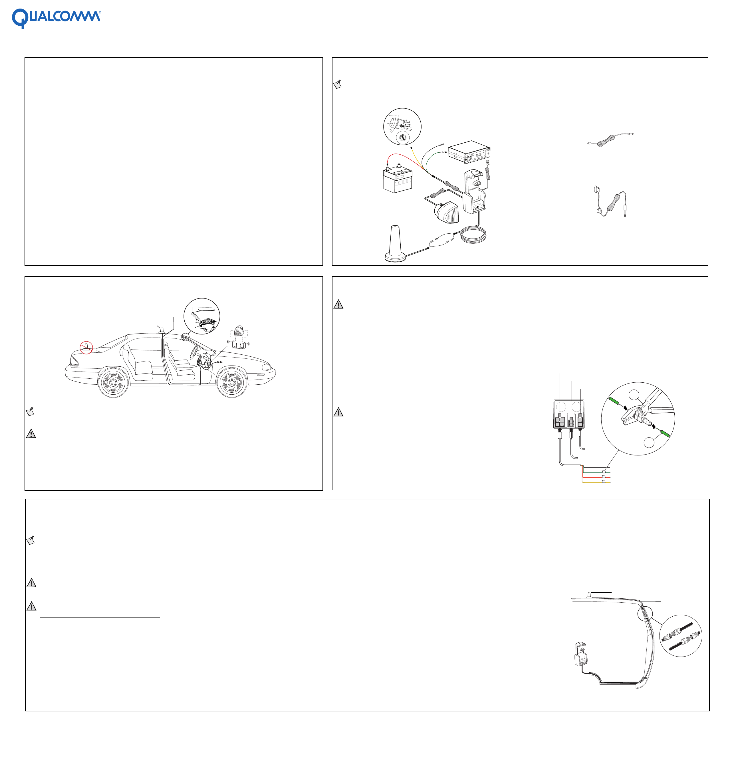
2 How the components fit together
Note
See the QUALCOMM Globalstar GIK-1700 Globalstar Installation Kit User Guide for a list of components.
Globalstar Installation Kit Standard Components Globalstar Installation Kit Optional Accessories
Accessory
position
ACC
OFF
START
LOCK
S
EN
S
L
P
DS
1
2
F
F
O
3
S
S
T
A
B
D
AC
P
M
Battery
O
C
ND
U
O
S
E
O
D
I
O
D
M
U
A
6
L
TA
I
G
I
D
45
E
C
F
R
U
U
H
S
O
S
3
T
A
PE
E
R
2
1
F
F
O
E
S
A
E
L
E
R
USB
Cable
GDC-1700
Privacy
Headset
GHS-1700
3 Where to install the components
Hands-Free
Antenna
cable
Antenna
Note
The installation of the kit components may vary according to the make and model of the vehicle.
Caution
Minimum Separation Distance Requirements
The antenna must be installed so as to maintain a 25 cm (10 inch) separation distance
between the antenna and the people within or n ear the vehicle to ens ure compliance
with the maximum permissable exposure (MPE) requirements. See Step 5 for
antenna Minimum Separation Distance Requirements.
microphone
Phone and
cradle
Hands-Free
speaker
To power
680AA_00
4 Connecting the leads on the antenna cable
Caution
Before connecting the antenna cable to the GIK, connect the leads first and follow the sequence below.
Whether the vehicle ignition has an ACC position or not, connect:
• Black lead ground (GND) to a clean unpainted metallic part of the vehicle.
• Green lead (STEREO MUTE) to the audio system, if applicable.
• Red lead to the positive te rminal of the ve hicle battery .
• If the vehicle ignition has an ACC position, connect the yellow lead to the Power Sense ACC position.
• If the vehicle ignition does not have an ACC position, connect the yellow lead to
the ON position of the ignition (Power Sense).
• Connect the micropho n e and speaker to the G IK .
• Connect the antenna cables to the cradle.
• Connect the data ca b l e (not included) to the GIK.
• Connect the optional privacy headset to the GIK.
• Connect the antenna cable to the GIK.
Caution
Exceeding the following input voltage and current
values causes the power fuse to open, requiring it to be
replaced.
Maximum input voltage is 16.0 volts.
Maximum input current is 2 A.
Power
Speaker
Microphone
Black lead
Green lead
Red lead
Yellow lead
2.
1.
Ground
STEREO MUTE
Battery terminal (+)
ACC (or ON) position
549AA_1999Q
5 Mounting the antenna
The antenna is required for satellite communication when the p hone is used inside a vehicle. It should be mounted on the roof of the vehicle with an unobstructed view of the sky. You can attach it to the roof of the
vehicle using a magnet or a ski rack type mount, or permanently bolt it in place.
Note
Check with your service provider for avai lable antenna mounti ng options.
When you mount the antenna using a magnet, check the surfac e of the magnet be fore you put the ante nna on the car. The ant enna is not designed for high speed driving, so use moderate speeds if it is mounted on the roof. Be sure that the connector between the antenna and the antenna cable
(45-C6162-1) is inside the vehicle.
Be sure to route the antenna cable through the weather strip without pinching it. Use only the antenna cables that come with the kit when connecting the antenna and do not cut or modify the antenna cable.
Caution
It is not recommended that you mount the antenna on the trunk or a lower surface. Performance could be affected by the shadow effect of the car.
Caution
Minimum Separation Distance Requirements
As discussed in the GIK-1700 Globalstar Instal lation Kit User Guide section on Exposure to Radio Frequency Signals, when the antenna is tran smitting it is necessary that at least a 25 cm (10 inch)
line-of-sight separation distance be maintained between the antenna and the people within or near the vehicle, above the horizon of the antenna (above and to the side of the antenna).
Maintaining this separation distan ce will ensure complia nce with the maximum permissable exposure (MPE) requirements of the FCC rules and the international standards referenced in the user
guide section mentioned above. A 25 cm separation distance is not required below the antenna horizon, inside the vehicle. Moun ting the antenna at least 25 cm from the edge of the vehicle roof will
satisfy the separation distance requirement under normal use condition s.
GIK-1770
Carpet
Antenna cable
45-C6162-1
80-C6304-1 Rev B
441AA_00
 Loading...