

Page 1
HeatMultiwatt
IMPO
NOTE: This product must be installed by a certified electrician in
accordance with local codes.
Traces of smoke
amounts of oil leaked on heating coil during manufacturing. It will
g
globalindustrial.ca
Assembly Instructions Instrucciones de Ensambla
Customer Service
US: 1-800-645-2986
Servicio de atención al Clien
México: 01.800.681.6940
080916
small or odor when unit is initiated indicates that
or shock, injury fire, electrical reduce risk of
notuse other Any manual. this in described as only r
similarand areas laundry bathrooms, in use for intended ot
DE CFDistribucion Industrial Globales S DE RL
ectives d’assemblageDir
Service à la clientèle
Canada: 888-645-2986
evaporate quickly
location is well ventilated during operation. It is normal for the unit
to emit sounds w
When using ele
to r precautions
property damage
Read all instructions prior to using heater.1.
Heater will be hot when in use. Prevent bare skin from touching hot surface2.
to avoid injury. Keep combustible materials such as but not limited to
furniture, bedding or clothing at least 3 feet (0.9 m) away from heater.
Extreme caution and supervision is necessary when heater is used3.
near children or pets and when the heater is left operating while
unattended.
Always switch off heater when not in use.4.
Do not operate heater if unit malfunctions, has been dropped, or is damaged5.
in any way. Disconnect power at service panel and have heater inspected
by a reputable electrician before reusing.
Do not use outdoors.6.
To disconnect heater, turn off power circuit at main disconnect panel.7.
For wall or ceiling installation, do not install less than 8 feet (2.4 m) high8.
Model 653577
1
from floor and closer than 1 foot (0.3 m) to any adjacent vertical surfaces
or walls. Keep at least 4.5 inches (11.5 cm) from back wall (with or without
wall hanging mounting bracket).
Do not insert or allow foreign objects to enter any ventilation or exhaust9.
opening as this may cause electric shock, fire or damage to heater.
To prevent a possible fire, do not block air intakes or exhaust in10.
any manner.
Units contain hot and arcing internal equipment. To reduce the risk of fire,11.
do not use in areas where gasoline, paint, or flammable vapors and liquids
are used or stored.
heater this Use 12.
recommended by the manufacturer may cause fire, electric shock
or injury.
no is heater This 13.
indoor locations. Never position heater near water.
WARNING
Please read all instructions before using this he
SAVE FOR FUTURE REFERENCE
Outdoor Ceiling Fan, 60 inch
Model: 292677
READ AND SAVE THESE
INSTRUCTIONS
Page 2
Outdoor Ceiling Fan, 60 inch
8
1
2
3
4
5 6
7
9
10
11 12
Read Instructions carefully before assembling or installing your fan. It is important that
you observe all safety information to help
prevent personal injury and/or property damage.
1. Installation work and electrical wiring should be done
by qualified persons only in accordance with all
applicable codes and standards.
2. Unplug or disconnect the fan before servicing.
3. Use this fan only in the manner intended by the
manufacturer. This fan is intended for permanent
installation and to be used for air circulation only.
4. The secondary support cable included with the fan
must be properly connected.
5. The fan shall be supported directly from the building
structure.
Caution: To reduce risk of injury, use only the
enclosed hardware as the primary means of support.
6.
7.
8.
9.
10.
1.
1
o
T
he
t
bal
ns
i
Cei
eas
l
bet
hen
W
houl
s
ai
or
The
eas
l
c
ac
Do
ug.
pl
ac
f
o
T
us
ont
c
educ
r
ade
bl
i
anc
or
f
t
er
ng
i
l
en
t
t
ween
m
d
ur
t
r
uppor
s
80
t
s
es
not
Di
y
t
i
l
i
educ
r
hi
t
e
ol
r
he
t
e
br
he
t
ng
gn
ei
ans
f
eet
f
ades
bl
ount
at
be
enc
bul
t
pounds
es
i
or
oper
ar
c
s
ex
or
f
e
an
f
s
dev
ac
i
he
t
c
i
wi
ng
t
d
i
r
k
bl
obj
hout
t
abov
ed
eas
l
e
hat
e
at
an
f
am
t
wi
es
of
k
s
when
s
et
ades
t
ec
e
and
a
n
i
one
t
ay
m
beam
or
(
i
m
any
or
nat
i
k
s
i
r
ot
h
.
per
,
s
guar
l
f
adj
c
he
t
ght
f
r
on
i
of
her
or
n
i
oor
at
f
c
m
an
et
i
f
onal
s
i
c
bet
ds
wi
ac
hedr
oot
aus
us
wei
be
wi
ur
and/
e
r
pes
y
t
i
al
t
ns
eani
l
ween
e
ar
adequat
h
t
wal
ent
c
al
om
r
f
an
f
e
be
t
ght
added)
a
h
t
an
o
t
n
or
ec
el
or
of
ur
nj
ng
i
l
ng
o
t
ei
t
t
apabl
c
of
dam
epai
r
t
ol
s
User’s Manual
not
do
,
y
k
ac
br
he
t
Do
an.
f
he
t
an
f
ng
i
at
ot
r
ed
l
al
t
ns
i
be
ear
l
c
e
hi
s
ni
ur
f
,
s
l
ade
bl
ng,
i
l
ed
angl
he
.
way
s
o
hol
of
e
us
pl
an
f
he
t
.
or
c
aged
ed
z
i
hor
aut
.
r
,
k
hoc
s
c
i
r
s
e
at
t
s
d-
i
bend
,
s
et
not
ades
bl
at
anc
ng,
ps
i
t
oof
r
ng
di
any
or
d
er
s
not
do
peed
et
v
e
i
l
i
c
ne
at
e
c
.
.
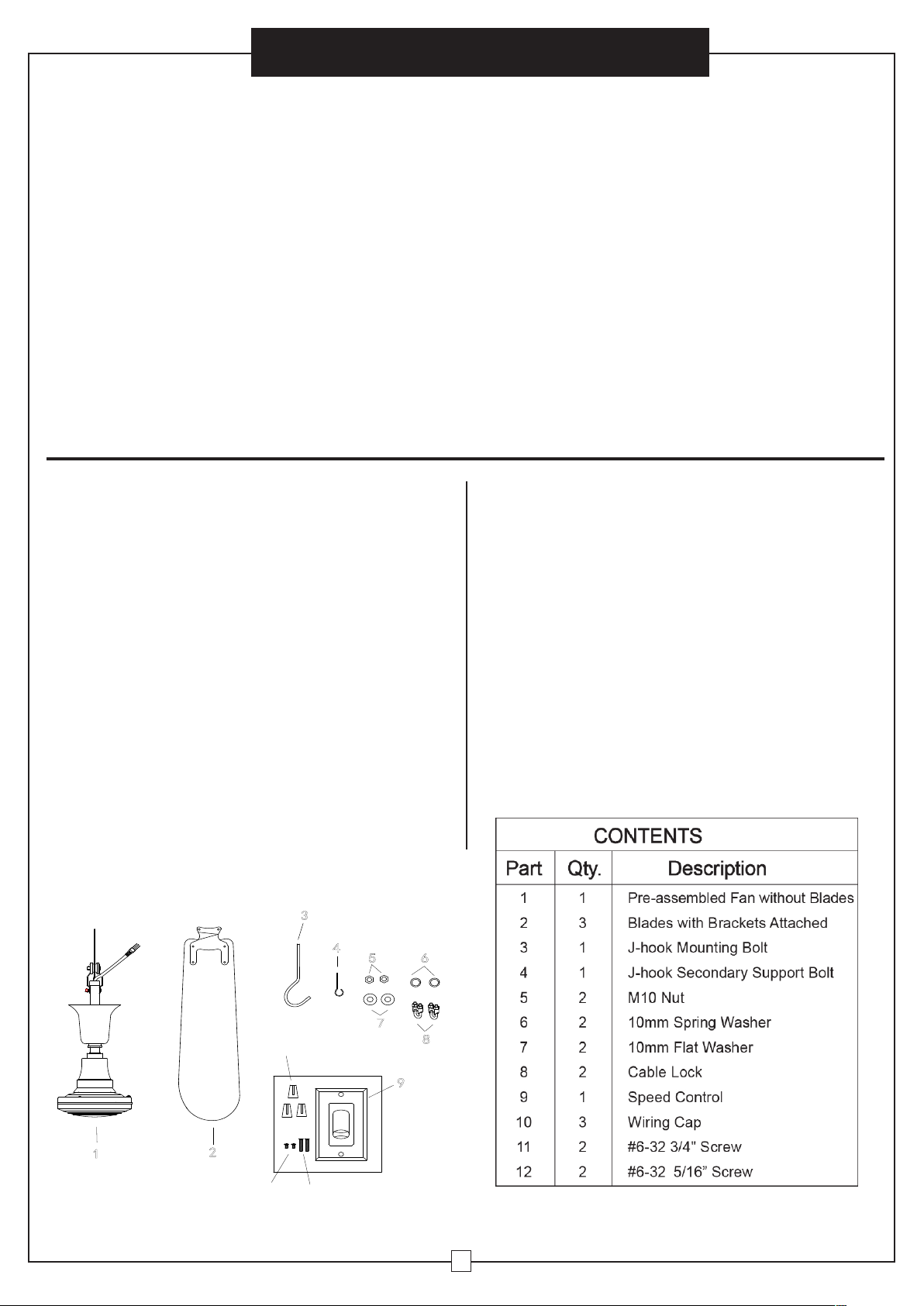
Unpacking Tools and Supplies
• Carefully remove fan and parts from carton and
check for shipping damage.
• Check parts list against carton contents.
• Do not install blades before mounting fan.
• Slot, Phillips head and Screwdrivers
• Adjustable crescent wrench
• Grounded metal outlet box with single recep
tacle
• Drill Bit size: 11~12mm
Electrical Hookup
Technical Specification
1. All electrical hookups should be made by a
qualified person.
2. The installation shall be in accordance with the
local codes.
3. Check state and local codes to assure proper
hookup.
4. Disconnect power at main service panel.
5. Lock in open position and tag it to prevent un
expected power application.
6. Check that power source conforms to electri
cal requirements of fan.
Outdoor Ceiling Fan, 60 inch
Model: 292677
Volt: 120V
Frequency: 60Hz
Watts: 107W
Current: 1.2A
2
Page 3

User’s Manual
3
7
5
6
5
6
7
5
7
6
3
4
6
1
2
1
”
top bell
set screw
down rop
power cord
safety cable
cable locks
rubber grommet
support blacket
1/8"
Fibe
r Pa
d
Bla
d
e
B
ra
c
ke
t
Bla
de
Bolt
s
Rub
be
r
W
a
s
he
rs
Fla
t
W
a
s
he
r
G
a
s
ke
t
Co
v
e
r
Fo
r downward ai
r flow
For upward air flow
All blades MUS
T face the
same direction.
Outdoor Ceiling Fan, 60 inch
Assembly Instructions
J-Hook Mounting
. Assemble M10 nut (5), 10mm spring washer(6)
1
and 10mm flat washer (7) onto the J-hook
mounting bolt (3) as shown below.
(Do not replace J-hook mounting bolt (3) with a lag
bolt.)
joist
2. Using a drill and drill bit, drill a hole thru joist.
Insert J-hook mounting bolt (3) with assembled
hardware into hole and secure with 10mm flat
washer (7), 10mm spring washer(6) and M10 nut
(5) as shown below.
Fully secure J-hook mounting bolt (3) to joist by
snugging top and bottom nut.
3.1-1/2” from installed J-hook mounting bolt (3), drill
a small pilot hole for mounting the J-hook
secondary support bolt (4).
Using pilot hole as your guide, install J-hook
secondary support bolt (4) for secure installation
ensuring all bolt threads are fully engaged.
joist
Hanging fan
1. Once top of unit has passed the safety in spection,
install unit.
Insert rubber grommet into the cradle of the J-hook
mount bolt (3) until fully seated and insert loop of
safety cable into J-hook secondary support (4) bolt
as shown.
2.Slide top bell up to cover both J-hook (3&4), leaving
an 1/8” gap between top of bell and hanging
surface and secure in place by tightening set screw.
(The 1/8” gap is required to ensure that down rod is
allowed to hang properly and not be forced off center
causing fan to wobble or vibrate.)
Attach Blades
Preparing to hang fan
1. Loosen set screw on top
bell and slide top bell
down to expose top of
down rod.
2. Attach cable locks (8) onto the cable for secure
installation. Inspect the hanging and installation
components to ensure that there is no shipping
damage.
Check that power cord is free from cuts or abrasions.
Check that support bracket and rubber grommet
are secure.
Check that BOTH cable locks (8) on safety
cable are tight.
TOP
BOTTOM
All blades MUST face the same
direction.
3
Page 4

Outdoor Ceiling Fan, 60 inch
User’s Manual
1. Bolts, flat washers, and fiber pads for at taching
blades are located on the motor housing.
2. Brackets come already installed on blades.
. Remove bolts from fan motor.
3
4. Leaving fiber pad in place on motor housing, set
bracket over holes and reinstall the bolts in their
original holes. Tighten into motor housing. Do not
over tighten.
5. When all three blades are attached, turn power
back on and test function.
Wiring Diagram
Hot Black
Black Black
120 VAC
60Hz
Control
Black
or
Red
Fan
Neutral
White
3. Remove the two insulated wires from the old
switch. Using the wire connectors provided, attach
one of the insulated wires to either of the black
wires on the new fan control switch.
Attach the second insulated wire it to the other
black wire on the new fan control switch.
Attach the new fan control to the outlet (wall) box
and secure with 2 outlet box screws, reattach the
switch cover with switch cover screws.
Wall control installation
instruction
Warning
To reduce rick of fire, electric shock, and/or personal
injury, wire only a single wall-control panel/switch and
ceiling fan unit together. Wiring two or more ceiling
fans to any single wall-control panel/switch may
cause the circuitry to fail by overheating.
Please do not attempt to defeat this feature of the
ceiling fan system as doing so will void the warranty,
both explicit and implicit stipulations thereof.
Outlet Box
Wall Plate Switch
1.Turn power OFF at fuse box or circuit breaker and
remove the existing wall plate and switch
2. Make wire connections and secure with wire
nuts supplied.
.
Screw
Speed
Control
Outlet Box
Operation
Turn on the power and check operation of fan.
The wall control the fan speeds as follows:
0 - off; 1 - high; 2 - medium high; 3 - medium; 4 - low.
Speed settings for warm or cool weather depend on
factors such as room size, ceiling height, number of
fans and so on.
The slide switch controls direction, forward or re-
verse.
Warm weather - (Forward) Fan
turns counterclockwise direction. A
downward air flow creates a cooling
effect.
This allows you to set your air conditioner on a higher temperature setting without affecting your comfort.
Cool weather - (Reverse) Fan turns
clockwise direction. An upward airflow moves warm air off the ceiling
area.
This allows you to set your heating
unit on a lower setting without affecting your comfort.
4
3
Page 5

User’s Manual
Outdoor Ceiling Fan, 60 inch
The slide switch has been included, it located on
the couple yoke. Please loosen the set screw on the
top of yoke cover, then slide the bell up to the down
rod, after adjust the slide switch, please repeat the
yoke cover.
NOTE: Turn off and wait for fan to stop before
changing the setting of the forward/reverse slide
switch.
Reverse Direction
Maintenance
. Because of the fan’s natural movement,
1
some connections may become loose.
Check the support connections, brackets,
and blade attachments twice a year. Make
sure they are secure.
2. Clean your fan periodically to help maintain
its new appearance over the years. Do not
use water when cleaning. This could damage
the motor, or the wood, or possibly cause
electrical shock.
3. Use only a soft brush or lint-free cloth to
avoid scratching the finish. The plating is
sealed with a lacquer coating to minimize
discoloration or tarnishing.
4. There is no need to oil your fan. The motor
has permanently lubricated bearings.
1. Remove screw from bell.
2. Slide rubber gaskets and bell up to reveal
switch.
3. Slide switch to change motor direction.
4. Slide rubber gaskets and bell back down.
5. Align screw hole in bell and rubber gasket
with hole in down rod and reinstall screw.
TROUBLE SUGGESTED REMEDY
1. Check main and branch circuit fuses or circuit breakers.
2. Check wire connections as performed in step #9 of installation.
CAUTION: Make sure main power is turned off.
If fan does not start:
If fan sounds noisy:
3. Make sure forward/reverse switch is firmly in the right position.
Fan will not operate when switch is in the middle.
4. If the fan still will not start, contact a qualified electrician.
Do not attempt to troubleshoot internal electrical connections yourself.
1. Check to make sure all screws in motor housing are snug (not over
tightened).
2. Check to make sure the screws which attach the fan blade holder to the
motor are tight.
3. Some fan motors are sensitive to signals from Solid State variable
speed controls.
4. Allow “break-in” period of 24 hours. Most noises associated with a new fan
will disappear after this period.
TROUBLESHOOTING
If you have difficulty operating your new ceiling fan,
it may be the result of incorrect assembly, installation, or wiring. In some cases, these installation errors may be mistaken for defects.
If you experience any faults, please check this
Trouble Shooting chart. If a problem cannot be
remedied, please consult with your authorized electrician and do not attempt any electrical repairs yourself
.
If fan wobbles:
The following procedures should eliminate most of the wobble. Check for
wobble after each step.
1. Check that all blades are screwed firmly into blade holders.
2. Check that all blade holders are tightened securely to motor.
3. Make sure that canopy and mounting bracket are tightened securely to
ceiling joist.
4. If blade wobble is still noticeable, interchanging two adjacent (side by side)
blades can redistribute the weight and possibly result in smoother operation.
5
 Loading...