

Page 1
Instruction Manual
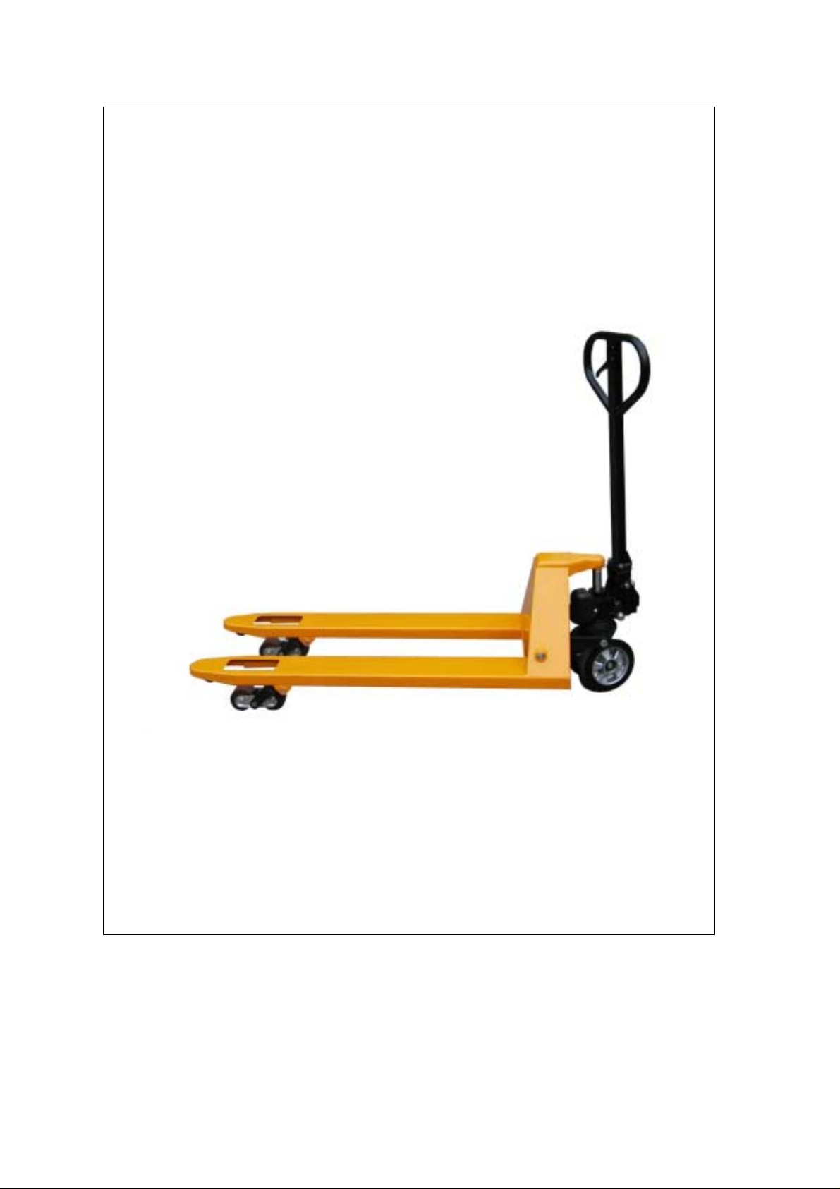
HAND PALLET TRUCK
(TX SERIES)
Note: Owner/Operator must read and understand this instruction
manual before using the hand pallet truck.
Page 2

Thank you for choosing our pallet truck. For your safety and correct operation, please
carefully read the manual before use.
NOTE: All of the information reported herein is based on data available at the time of
printing. The factory reserves the right to modify its own products at any time without
notice or incurring in any sanction. Please verify with the factory for possible updates.
1. GENERAL SPECIFICATIONS
Standard Model TX20S TX20L TX25S TX25L
Quick Lift Model TXQ20S TXQ20L TXQ25S TXQ25L
Capacity (kg) 2000 2000 2500 2500
Max. Fork Height (mm) 205(or195)
Min. Fork Height (mm) 85(or75)
Fork Length (mm) 1150 1220 1150 1220
Width Overall Forks (mm) 530 685 530 685
Individual Fork Width (mm) 150
Load Wheel Diameter (mm)
Steering Wheel Diameter (mm)
Net Weight (kg) 72 77 76 79
Special fork length are available 800, 900, 950, 1000, 1220,1500mm.
Materials and specification are subject to change without notice.
φ80x60(orφ70x60)Nylon , Polyurethane
φ200(orφ180)Nylon, Polyurethane, Rubber
2. TO ATTACH HANDLE TO PUMP UNIT
2.1 Loosen the setting screw (140H) on the crank link (139H).
2.2 Remove three screws (H109) and three spring washers (H110) from the base (103).
2.3 Place the handle (H101, H101A, H101(JR), H101(FR)) on the base (103), please
note: Feed the rod and chain (H107) through the centre of the base (103) and axle (109).
2.4 Insert three screws (H109) with spring washers (H110) into the base (103). Then
tighten them securely.
2.5 Raise the crank link (139H) and put the pin on rod and chain (H107) into the
groove of crank link (139H).
3. TO ADJUST RELEASE DEVICE
On the handle of the pallet truck, you will find the control lever (H106) which can be set
in three positions (See Fig. 1):
LOWER=to lower the forks; NEUTRAL=to move the load; ASCENT=to raise the forks.
After assembling the handle, you can adjust the three positions.
3.1 First tighten the setting screw (140H) on the crank link (139H) until the LOWER
position function works.
3.2 If the forks elevate while pumping in the NEUTRAL position, turn the setting
screw (140H) clockwise until pumping the handle does not raise the forks and
the NEUTRAL position functions correctly.
3.3 If the forks descend while pumping in the NEUTRAL position, turn the setting
screw (140H) counter-clockwise until the forks do not lower.
1
Page 3

3.4 If the forks do not descend when the control lever (H106) is in the LOWER position,
turn the setting screw (140H) clockwise until raising the control lever (H106) lowers
the forks. Then check the NEUTRAL position as per item 3.2 and 3.3.
3.5 If the forks do not lift while pumping in the ASCENT position, turn the setting
screw (140H) counter-clockwise until the forks elevate while pumping in the
ASCENT position. Then check the NEUTRAL and LOWER position as per
item 3.2, 3.3 and 3.4.
4. MAINTENANCE
4.1 OIL
Please check the oil level every six months. The oil capacity is about 0.3lt. Restore
the fluid level in the rubber reservoir to 5mm below the top, this must be with the
forks in the lowered position.
Use the hydraulic type oil according to temperature scale below.
Temperature Oil
-20℃~+40℃
L-HV46 Hydraulic oil
4.2 HOW TO EXPEL AIR FROM THE PUMP UNIT
Air may enter the unit when the seals are replaced. Lift the control lever (H106) to the
LOWER position, then move the handle (H101, H101A, H101(JR), H101(FR)) up and
down for several times.
4.3 DAILY CHECK AND MAINTENANCE
Daily check of the pallet truck can limit wear and tear of the unit. Pay special
attention to the wheels (127, F1510, F1511), the axles (F1512, F1515, F1516),
the handle (H101, H101A, H101(JR), H101(FR)), the forks (F1504) and lift and
lower control.
4.4 LUBRICATION
Use motor oil or grease to lubricate all moveable parts.
5. GUIDE TO SAFETY OPERATION
For safe operation of the Hand Pallet Truck, please read all warning signs and
instructions here and on the pallet truck prior to use.
5.1 Do not operate the pallet truck unless you are familiar with it and have been
trained or authorised to do so.
5.2 Do not operate the truck unless you have been trained and authorised. Give
special attention to the wheels, the handle assembly, the forks, and the lower
control.
5.3 Do not use the truck on sloping ground.
5.4 Never place any part of your body in the lifting mechanism or under the forks
or load. Do not carry passengers.
5.5 We advise that operators should wear gloves and safety shoes.
5.6 Do not handle unstable or loosely stacked loads.
5.7 Do not overload the truck.
5.8 Always place loads centrally across the forks and not at the end of the forks
(See Fig. 2).
2
Page 4

5.9 The capacity of the truck assumes an evenly distributed load with the centre of the
load being at the halfway point of the length of the forks.
5.10 Make sure that length of the forks matches the length of the pallet.
5.11 Lower the forks to lowest height when the truck is not being used.
5.12 In other specific conditions the operators should take extra care in operating the
truck.
6. TROUBLES SHOOTING
NO TROUBLE CAUSE ACTION
The forks do not lift
1
to maximum height.
The forks do not lift
2
up.
The forks do not
3
descend.
4
Leaks
The forks descend
5
without being
lowered.
*NOTE: DO NOT ATTEMPT TO REPAIR THE PALLET TRUCK UNLESS YOU ARE
TRAINED AND AUTHORIZED TO DO SO.
-Not enough hydraulic oil. -Add more oil.
-Not enough hydraulic oil.
-The oil has impurities.
-Discharge valve is out of
adjustment.
-Air in the hydraulic oil.
-The rod (102) and the
cylinder (159H) are deformed
resulting from a seriously
unbalanced load.
-A part has been broken or
been deformed resulting
from unbalanced load.
-The setting screw (140H) is
not in the correct position.
-Seals worn out or damaged.
-Some parts may be cracked
or worn out.
-Impurities in the oil cause
the discharge valve (B) to fail
to close.
-Air in the oil.
-Seals worn or damaged.
-Discharge valve (B) is out of
adjustment.
3
-Pour in more filtered oil.
-Change the oil.
-Adjust the setting screw
(140H) (See item 3.5).
-Expel the air (See item 4.2).
-Replace the rod (102) or
cylinder (159H).
-Repair or replace
component.
-Adjust the setting screw
(140H) (See item 3.4).
-Replace seals with new
ones.
-Check and replace with new
ones.
-Replace with filtered oil.
-Expel the air (See item 4.2).
-Replace with new ones.
-Adjust the setting screw
(140H) (See item 3.3).
Page 5

4
Page 6

Pump Assembly
5
Page 7

Parts List of Pump Assembly
PARTS
NO.
101
102
103
104
105
106
107
108
109
110
111
112
113
114
115
116
117
118
119
120
121
122H
123A
124A
125
126
127A
127B
127C
127D
128
129
130
131
132
133
134
135
DESCRIPTION Q’TY
Steel ball
Rod
Base
Steel roller
Bushing
Pin
Shaft
Retaining ring
Axle
Screw
Washer
Spring
Pressure rod
Steel ball
Pressure valve body
Split ring
O-ring
Washer
Steel needle
Bushing
Pin
Pump body
Dust cover
Bearing
Steering wheel axle
Bearing
Steering wheel, Nylon
Steering wheel, Polyurethane
Steering wheel, Poly/Nylon
Steering wheel, Rubber
Retaining ring
Steel ball
Discharge valve body
Spring
O-ring
Discharge valve shaft
Valve taper core
Spring
1
1
1
1
1
1
1
2
1
1
1
1
1
1
1
1
2
2
1
2
2
1
1
1
1
4
2
2
2
2
2
1
1
1
1
1
1
1
6
PARTS
NO.
136
137
138
139H
140H
141
142
143
144
145
146
147
148
149
150
151
152
153A
154
155
156
157
157-1
158H
159H
160H
161H
162H
163H
164H
165H
166
167
168
169
170
171
DESCRIPTION Q’TY
Pressure regulating screw
O-ring
Screw
Crank link
Setting screw
Nut
Parallel pin
Retaining cover
Spring cover
Spring
Pump rod
Dust proof ring
Pump cylinder
Seal ring
Nylon bushing
Red copper washer
Retaining ring
Rhombus plate
Pin
Dowel pin
Dust proof ring
O-ring
O-ring
O-ring
Cylinder
Seal ring
O-ring
Filler plug
Reservoir cover
Screw
Reservoir
Retainer
Retainer
Retainer
O-ring
Retainer
Dust cover
1
1
1
1
1
1
1
1
1
1
1
1
1
1
1
1
1
1
2
2
1
1
1
1
1
1
1
1
1
2
1
3
1
1
1
1
2
Page 8

Quick Lift Pump Assembly
7
Page 9

Parts List of Quick Lift Pump Assembly
PARTS
NO.
101
102
103
104
105
106
107
108
109
110
111
112
113
114
115
116
117
118
119
120
121
122H
123A
124A
125
126
127A
127B
127C
127D
128
129
130
131
132
133
134
135
136
137
DESCRIPTION Q’TY
Steel ball
Rod
Base
Steel roller
Bushing
Pin
Shaft
Retaining ring
Axle
Screw
Washer
Spring
Pressure rod
Steel ball
Pressure valve body
Split ring
O-ring
Washer
Steel needle
Bushing
Pin
Pump body
Dust cover
Bearing
Steering wheel axle
Bearing
Steering wheel, Nylon
Steering wheel, Polyurethane
Steering wheel, Poly/Nylon
Steering wheel, Rubber
Retaining ring
Steel ball
Discharge valve body
Spring
O-ring
Discharge valve shaft
Valve taper core
Spring
Pressure regulating screw
O-ring
1
1
1
1
1
1
1
2
1
1
1
1
1
1
1
1
2
2
1
2
2
1
1
1
1
4
2
2
2
2
2
1
1
1
1
1
1
1
1
1
8
PARTS
NO.
138
139H
140H
141
142
143
144
145
147
151
152
153A
154
155
156
157
157-1
158H
159H
160H
161H
162H
163H
164H
165H
166
167
170
171
M625
M626
M627
M628
M629
M630
M631
M632
M633
M634
M635
DESCRIPTION Q’TY
Screw
Crank link
Setting screw
Nut
Parallel pin
Retaining cover
Spring cover
Spring
Dust proof ring
Red copper washer
Retaining ring
Rhombus plate
Pin
Dowel pin
Dust proof ring
O-ring
O-ring
O-ring
Cylinder
Seal ring
O-ring
Filler plug
Reservoir cover
Screw
Reservoir
Retainer
Retainer
Retainer
Dust cover
Seal ring
Pump cylinder
Pump rod
O-ring
Big spring
Steel ball
Small spring
Steel ball
Spring base
Plug
Pin
1
1
1
1
1
1
1
1
1
1
1
1
2
2
1
1
1
1
1
1
1
1
1
2
1
3
1
1
2
1
1
1
1
1
2
2
1
1
1
1
Page 10

Parts List of Frame
PARTS
NO.
F1501
F1502
F1503
F1504
F1505
F1506
F1507
F1508
F1509
F1510A
F1510B
F1510C
F1511A
F1511B
F1511C
F1512
F1513
DESCRIPTION Q’TY
Torsion tube assembly
Spring pin
Torsion tube shaft
Frame
Bolt
Bushing
Plate
Nut
Pin
Nylon load roller, tandem type
Poly load roller, tandem type
Poly/Nylon load roller, tandem type
Nylon load roller, single type
Poly load roller, single type
Poly/Nylon load roller, single type
Axle
Roller
9
1
1
1
1
4
4
4
4
4
4
4
4
2
2
2
2
2
PARTS
NO.
F1514
F1515
F1516
F1517
F1518
F102
F103
F106
F108
F109
F111
F112
F115
F123
F124
F126
DESCRIPTION Q’TY
H-link
Axle
Axle
Washer
Pull rod
Bushing
Screw
Nut
Roller
Bushing
Bolt
Spring pin
Bearing
Nut
Pin
Pin
2
2
2
4
2
4
1
2
2
2
2
4
8/4
2
2
2
Page 11

Parts List of Handle
PARTS
NO.
H101
H101A
H101(JR)
H101(FR)
H102
H103
H104
H105
DESCRIPTION Q’TY
Handle
Handle
Handle
Handle
Spring pin
Spring leaf
Spring pin
Spring pin
1
1
1
1
1
1
2
1
10
PARTS
H106
H107
H108
H109
H110
H111
H112
NO.
DESCRIPTION Q’TY
Control lever
Rod and chain
Rubber cushion
Screw
Spring washer
Nylon roller
Spring pin
1
1
1
3
3
1
1
Page 12

Assembly list
Assembly Description
AH Pump unit
AHQ Quick lift pump unit
B Lowering valve ass’y
CH Lowering screw ass’y
D Hydraulic valve ass’y
E Handle seat ass’y
F1 Nylon steering wheel ass’y
F2 Polyurethane steering wheel ass’y
F3 Polyurethane/Nylon steering wheel ass’y
F4 Rubber steering wheel ass’y
G Handle ass’y
YH1A Nylon load roller ass’y (tandem type)
YH1B Polyurethane load roller ass’y (tandem type)
YH1C Polyurethane/Nylon load roller ass’y (tandem type)
YH2A Nylon load roller ass’y (single type)
YH2B Polyurethane load roller (single type)
YH2C Polyurethane/Nylon load roller ass’y (single type)
I1 Tandem nylon load roller system ass’y
L Rhombus plate ass’y
K Quick lift pump piston ass’y
M Spring cover ass’y
N Pump piston ass’y
W Safety valve ass’y
SH *Seal kit
SHQ *Seal kit
*Note: Seal kit include following parts: 111, 117, 118, 132, 137, 147, 149,
151, 156, 157, 157-1, 158H, 160H, 161H, 169, M625, M628.
11
 Loading...