

Page 1
México: 01.800.681.6940
Servicio de atención al Clien
US: 1-800-645-2986
globalindustrial.ca
g
User's manual Manual del usuario
Customer Service
Electric Convection H
Canada: 888-645-2986
Service à la clientèle
DE CFDistribucion Industrial Globales S DE RL
Manuel de l'utilisateur
Model 653557
090315
WARNING
Th
1
READ & SAVE THESE INST
N
Table of Contents
Important Instructions ....................................... 2
Parts List ........................................................... 2
Operating Instructions....................................... 3
Specifications.................................................... 3
Cleaning and Maintenance................................ 3
Storage.............................................................. 3
Troubleshooting................................................. 4
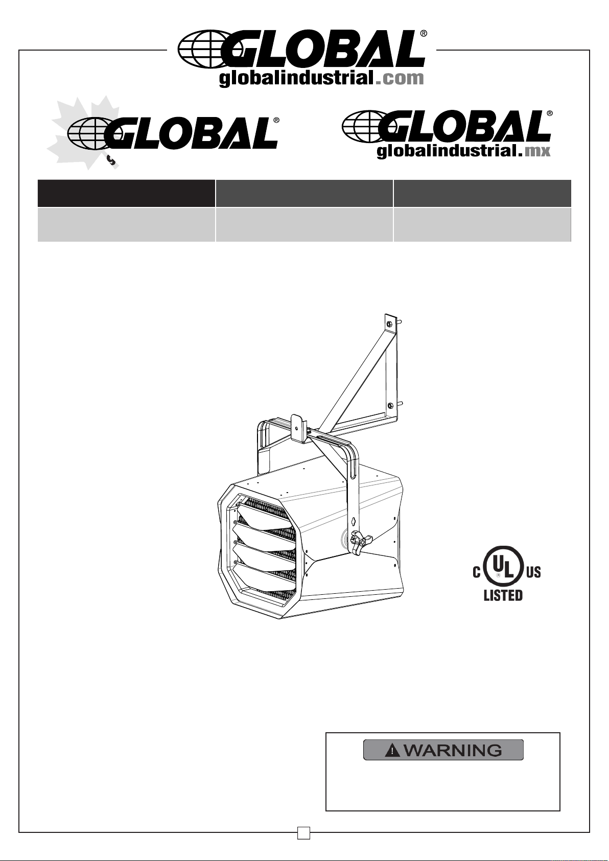
Horizontal Unit Heater
10KW - 240V - 1 or 3 Phase
Model:246102
Table of Contents
Important Instructions ................................... 2
Parts List ....................................................... 2
Specifications ................................................ 3
Installing Instructions ..................................... 3 - 4
Operating Instructions ................................... 5 - 6
Maintenance and Cleaning ............................... 6
Troubleshooting ............................................ 6
PLEASE READ ALL INSTRUCTIONS
BEFORE USING THIS HEATER
Page 2
Horizontal Unit Heater 10KW - 240V - 1 or 3 Phase
MAX
OFF
TEMPERATURE SETTING
ON
OFF
POWER
WALL
THERMOSTAT
INSIDE
THERMOSTAT
IMPORTANT INSTRUCTIONS
PLEASE READ ALL INSTRUCTIONS
BEFORE USING THIS HEATER
When using electrical appliances, basic precautions should
always be followed to reduce risk of fire, electrical shock and
njury to persons or property, including the following:
i
1.Read all instructions before using this heater.
.This heater is hot when in use. To avoid burns, do not let
2
bare skin touch hot surfaces. Keep combustible materials,
such as furniture, pillows, bedding, papers, clothes and
curtains at least 3 ft. (0.9 meters) from the front and top of the
eater and keep them away from the sides and rear.
h
3.Extreme caution and reasonable supervision is necessary
when any heater is used by or near children, invalids or pets
and whenever the heater is left operating and unattended.
4. Always switch off the heater when not in use.
5. Do not operate any heater after the heater malfunctions, has
been dropped or damaged in any manner. Disconnect power
at service panel and have heater inspected by a qualified
electrician before reusing.
6. Do not use outdoors.
7. To disconnect heater, turn off power to heater circuit at main
disconnect panel.
8. Do not install less than 6 feet (1.8 m) high from the floor and
closer than 1 foot (0.3 m) to any adjacent vertical surfaces or
walls. Keep at least 4.5 inches (11.5 cm) from the back wall
(with or without using the wall hanging mounting bracket).
User’s Manual
Traces of smoke or odor when unit is initiated indicates that small
amounts of oil leaked on heating coil during manufacturing. It will
evaporate quickly and should not re-occur. Make sure the appli-
nce location is well ventilated during operation. It is normal for the
a
unit to emit sounds when turned on for the first time.
Make sure that the room in which the appliance is located is well
ventilated during this operation.
9.Do not insert or allow foreign objects to enter any ventilation or
exhaust opening as this may cause an electric shock or fire, or
amage the heater.
d
10.To prevent a possible fire, do not block air intakes or exhaust
in any manner.
11.A heater has hot and arcing or sparking parts inside. To reduce
the risk of fire, do not use it in areas where gasoline, paint, or
flammable vapors and liquids are used or stored.
12.Use this heater only as described in this manual. Any other use
not recommended by the manufacturer may cause fire, electric
shock, or injury to persons.
13. This product must be installed by a certified electrician, in
accordance with local codes.
14. For supply cables, use 6 AWG (13.3 mm2) copper wires .
RISK OF FIRE, DO NOT USE AS A
RESIDENTIAL OR HOUSEHOLD
HEATER.
D
G
C
H
B
A
E
F
J
I
K
2
L
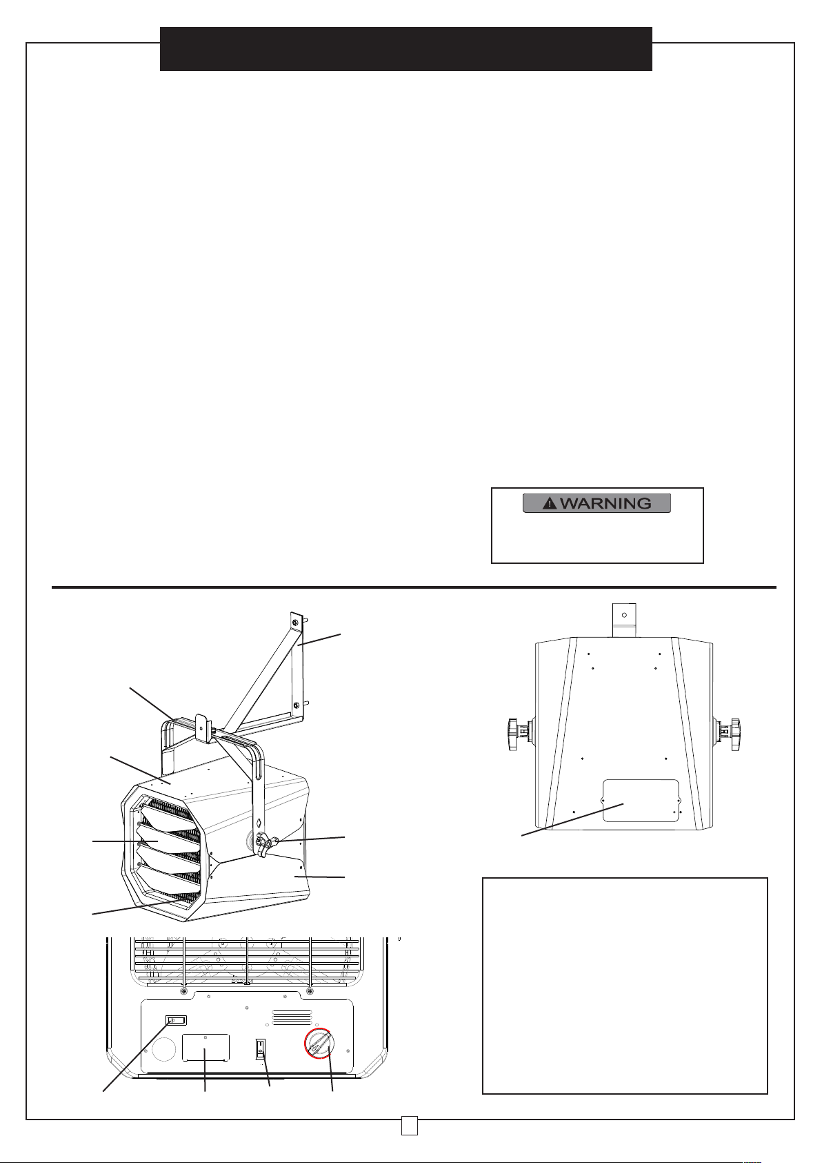
Parts List
A. Wall Mount Bracket
B. Ceiling Bracket
C. Upper Housing
D. Louver for air direction
E. Tilt adjustable knob
F. Lower Housing
G. Front Exhaust Grill
H. Select switch for built-in Thermostat or Wall
Thermostat
I. Inspection window (Inspection cover)
J. ON/OFF Switch
K. Thermostat knob
L. Wiring access window (wire connection cover)
Page 3
User’s Manual
Power
Ter m in a l
Block
Limit Overheat Cutout
(Wall thermostat)
External temperature control
(
Build in thermostat)
T
emperature control
Switch selector for build in
thermostat or wall thermostat
T
erm inal A
N
ot included
3 Phase
Terminal Block
CONTACTOR
COIL
Fan and Heater
S
witch
H1/3300W
H2/3300W
H3/3300W
3 Phase Wiring
NOTE:
1. 1 Phase Connection
2. 3 Phase Connection
For 3 Phase Wiring:
Connect lead wire [ W ] to terminal point [ W1 ]
and lead wire [ T ] to terminal point [ T1 ]
G
W
Horizontal Unit Heater 10KW - 240V - 1 or 3 Phase
Product Specification
Model 246102
Manufacturer
Model
PH-9100WTX
Length Inches 18.11
Width Inches 16.73
Height Inches 16.06
Wire Size For
nstallation
I
6AWG
Net Weight Lbs 48.24
Construction Cold Rolled Steel
Btu High 34,129
Cfm High 600
Outlet Air
Temperature
221°F @ Ambient
Temp. 77°F
Voltage 240V
Phase
Amps
Watts
Kilowatts
1 or 3
41.7
10,000
10
Circuit Breaker
Amp rating
Safety Tip-Switch
Limited Warranty
Years
Certification UL,cUL
60A
No
1
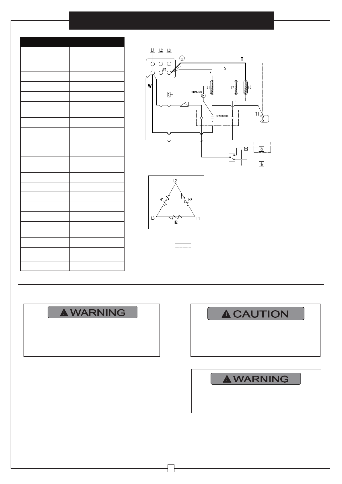
Wiring Diagram
NOTE:
To use an external temperature controller (a
wall thermostat). Detached the black wire
that short current Terminal "A", and then insert
the lead wires from wall thermostat to Terminal
A and secured. Switch the selector switch to
Wall thermostat to use it.
For single phase connection, please connect
to L1 and L3.
For 3 phase connection, move red wire
marked "W" connecting terminal L1 to W1 and
move red wire marked “T” connecting terminal
L3 to T1.
INSTALLING INSTRUCTIONS
All wiring must be installed by a certified
electrician according to the local electrical
codes. The ceiling heater must be grounded in
accordance with all national and local building
codes.
All Wiring procedures and connections shall be in
accordance with the national and local codes having
jurisdiction.
Prior to installation:
Disconnect the main supply connection.
Supply cables shall be 6 AWG (13.3 mm2) copper wires.
The heater must be connected to individual branch circuit
protected by 60 Amp circuit breaker only.
Supply cables must be equipped with a dual pole circuit
breaker rating at least 240V 60A/pole as main cutoff switch
of power connection to the heater.
Wiring compartment for accommodating supply cables and
pigtail leads are adequate and measured free space of
2524.67 cm3 .
High temperature, risk of fire, keep electrical
cords, drapery, furnishings, and other
combustibles at least 3 feet (0.9 m) from the
front of the heater and away from the side
and rear.
To reduce the risk of fire, do not store or use
gasoline or other flammable vapors and
liquids in the vicinity of the heater.
3
Page 4
10
Horizontal Unit Heater 10KW - 240V - 1 or 3 Phase
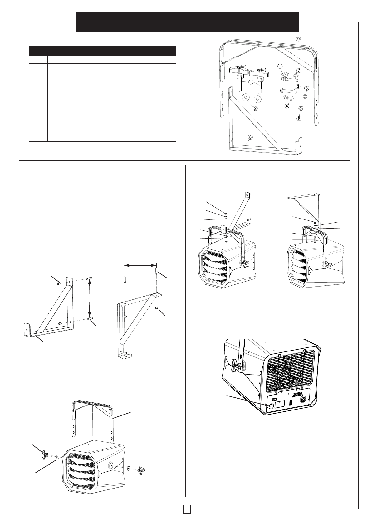
CONTENTS
Part Qty. Description
1
2
3
4
5
6
7
8
9
10
ilt adjustment knob
2
T
2
Rubber washer
1
2
1
1
2
1
1
2
ex bolt M10 x 60mm L, zinc plated
H
Washer, 10mm, zinc plated
Spring washer
Nut
xpansion bolt
E
Wall hanger
Handle
Expansion Nut
User’s Manual
Wall Mount Installation Instructions:
1. Install the unit at least 6 feet (1.8 m) away from the floor. This
minimum distance must be maintained.
2. Do not install closer than 1 foot (or 0.3 m) to any adjacent
vertical surfaces or walls.
3. Keep at least 4.5 inches (11.5 cm) from the back wall (with or
without using the wall hanging mounting bracket).
4. Determine the mounting location on the wall/ceiling and mark
the hole locations.
5. Use a 0.48 inch(12mm) drill bit and drill (2) holes 2.75 inches
deep.
6. Insert the expansion bolts (7) flush to wall or ceiling.
7. Attach the mounting bracket (8) and secure with expansion
nut (10).
10
10.94 in
7
8
10.94 in
7
10
9. Insert washer (4) and hex bolt (3) through mounting bracket
(8) and heater handle (9). Tighten with washer (4), spring
washer (5) and nut (6).
6
5
4
4
3
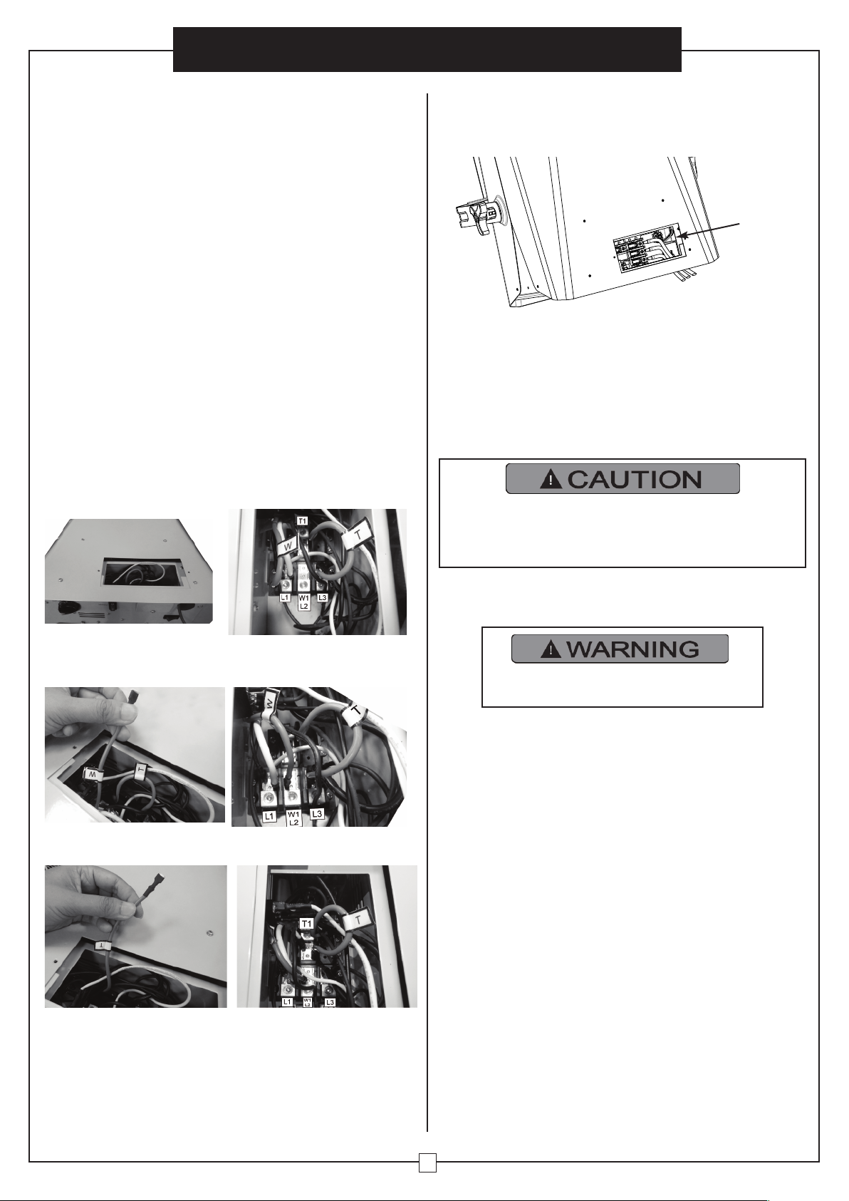
Wire Connection:
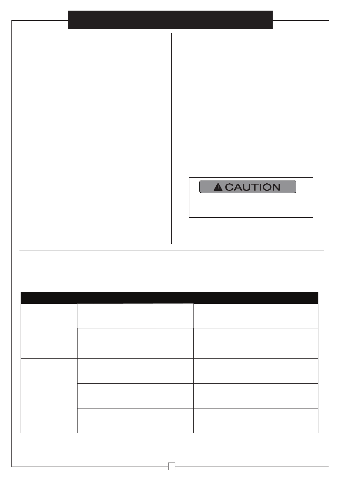
10. Loosen the screw to remove the inspection window cover in
the rear of the heater.
11. Run the electrical power supply cable in conduit.
12. Secure the conduit to the back plate via the knock-out hole.
6
4
3
5
4
Note: The bracket must be firmly attached to the wall before
hanging the unit
8. Hook the unit to the mounting bracket (8) and let the unit hang
from the mounting bracket (8).
8
1
2
Knock-out Hole
13. Make the connections properly with connectors which are
suitable for the conductor size, including grounding wirings.
Pull all the conductors from the conduit. Strip 3/4 inch of insulation from ground conductors. Make a right angle bend in the
green(green/yellow) pigtail and place its stripped end next to the
stripped ends of the other green(green/yellow) supply cable.
Make sure that the bare ends are tight together and square.
Using lineman's pliers, twist the bare ends tightly together in a
clockwise direction, then screw one of the wire nuts tightly on
the spliced conductors. Check to be sure that no bare copper
shows from beneath the wire nut.
4
Page 5
User’s Manual
Horizontal Unit Heater 10KW - 240V - 1 or 3 Phase
14. For the rest of the supply cable, strip 0.4inch (10mm) of the
insulation.
15. Identify the supply cables’ phase and insert into respective
L1, L2, L3 terminal. Secure the hex nuts.
16. And after making the connections, arrange the pigtail leads
of unit and power supply wires in the wiring compartment.
17. Replace the wiring cover and lock in place with the screw.
18. Consult NEC code for other types of approved electrical wire
splices & wire connectors.
SINGLE AND 3 PHASE CONNECTION
ingle phase connection:
S
This heater is capable to connect with single phase or 3 phase
power. Check the power source and use the correct wiring for
connection.
Note:The heater is factory wired with a Single phase configuration. Confirm that the power source is Single phase as well.
1.Open the access window.
2.Connect the 2 supply cords to L1 and L3.
3.Replace the cover and lock in place with the screw.
3 phase connection:
For a 3 phase connection, wiring has to be modified.
1.Open the access window. Look for the internal red wires which
mark “T” and “W”.
How to connect an external temperature controller (a
all thermostat):
w
1.Open the access window (wire connection cover), at the
corner is the terminal block. This is Terminal A.
erminal A
T
2.Insert the lead wires from the external temperature controller
nto the terminal and secure.
i
3.After making the connections, arrange the leads back into the
wiring compartment.
4.Replace the cover and lock in place with the screw.
5.Remember to switch the selector switch to “WALL
THERMOSTAT” position.
NOTE: when the selector switch is at “INSIDE
THERMOSTAT” position, the internal thermostat is in use.
1.Consult an electrician for an appropriate external
temperature controller (wall thermostat).
2.Install the external temperature controller by a certified electrician according to the electrical safety.
2.Unplug the red wire “W” and plug to the Terminal W1/L2
position.
3.Unplug the red wire “T” and plug to the Terminal T1 position.
4.Now the heater is of 3 phase wiring.
5.Check the power source is a 3 phase supply.
6.Connect the supply cords to L1, L2, L3.
7.Replace the cover and lock in place with the screw.
OPERATING INSTRUCTIONS
The heater must be properly installed
before it is used.
HAZARD OF ELECTRIC SHOCK, EXPLOSION, OR
ARC FLASH :
.
Apply appropriate personal protective equipment (PPE) and
follow safe electrical work practices. See NFPA 70.
.
A circuit breaker must be installed and serviced only by
qualified electrical personnel.
.
Always use a properly rated voltage sensing device to
confirm power is off.
The switch on the heater is to start the Fan and Heater.
Use the circuit breaker as power ON/OFF device. The
circuit breaker is to be installed by certified electrician
and shall be located in line of sight from the heater
location or shall be capable of being locked in open
position. Follow the operating instruction to reduce the
risk of fire, electric shock, injury or death.
.
Switch on the circuit breaker to turn on the heater power.
.
Press the switch at the back of the heater to turn on the fan
and heating function.
.
To turn off the heater, press the switch to turn off the fan and
heating function. And then switch off the circuit breaker. The
circuit breaker serves as the power disconnection means.
Temperature setting
The heater is capable to connect to an external wall thermostat.
If a wall thermostat has been connected to the heater. Make
sure which thermostat is in use. There is the selector switch:
“INSIDE THERMOSTAT” position is the internal thermostat.
“WALL THERMOSTAT” position is the external thermostat.
5
Page 6
Horizontal Unit Heater 10KW - 240V - 1 or 3 Phase
User’s Manual
ow to select a thermostat setting:
H
Using the built-in temperature controller (built-in
thermostat):
Note: The selector switch must be at the “INSIDE
THERMOSTAT” position.
1.Ambient temperature is regulated by adjusting the built-in
hermostat to a desired position.
t
2.Allow the unit to operate and warm up the room.
3.When the desired temperature is reached, turn the control
knob counterclockwise until the heater turns off. This is the ideal
setting.
4.The heater will start automatically when the room temperature
drops below this set point, and will turn off when the set point is
reached.
Using an external temperature controller (a wall
thermostat):
Note: The selector switch must be at the “WALL
THERMOSTAT” position.
1.To use an external temperature controller (a wall thermostat),
follow the installation instruction to connect the wall thermostat
first.
2.Press the selector switch to “WALL THERMOSTAT” position.
Now wall thermostat is selected and the built-in thermostat is
being disconnected.
3.Ambient temperature is regulated by adjusting the wall
thermostat to a desired position.
4.Allow the unit to operate and warm up the room.
5.When the desired temperature is reached, turn the control
knob counterclockwise until the heater turns off. This is the ideal
setting.
6.The heater will start automatically when the room temperature
drops below this set point, and will turn off when the set point is
reached.
MAINTENANCE AND CLEANING
There is no user maintenance except regular cleaning as
explained below. All other servicing or maintenance should be
performed by qualified service personnel.
Before any cleaning, make sure that:
1.Disconnect power supply at source. Switch off the circuit
breaker.
2.Wait for 60 minutes to ensure the heating element has cool
down before cleaning.
Regular Cleaning:
.Do not use cleaning liquid or other chemicals to spray on the
1
unit.
2.Interior dust can often be removed by using a vacuum cleaner
with a crevice tool attachment.
.To clean enclosure, use a clean, soft and lightly damp cloth to
3
gently wipe off the dirt from the surface of the unit. Be sure not
to wet the heating element and the switches. Allow the unit to dry
completely before using it.
Do not allow water to run into the interior of
the heater as this could create a fire or
electric shock hazard and damage the unit.
TROUBLESHOOTING
If your heater fails to operate, please follow these procedures:
This heater is intended to be ceiling or wall mounted. It has thermal cut-off protection. If the thermal cut-off protection trips, turn off
the power and switch off the circuit breaker. The unit should reset automatically after 10 minutes. If the thermal cut-off protection
trips again, consult a certified electrician to determine the reason for overheating.
Problem Probable Cause Solution
Turn the heater OFF; Switch off the circuit
breaker. Wait 10 minutes before turning on the
heater.
not been blown. This may occur if the receptacle is
shared between other high consumption appliances.
Remove any combustible items from the heater.
Ensure room in which heater is situated is well
ventilated.
Reposition the heater so there is enough space
around the heater to the adjacent walls.
Unit is not heating.
The heater is
producing a burning
smell.
ily
r
a
r
o
p
m
e
t
s
a
h
n
io
ct
e
t
o
r
p
t
a
e
h
r
ve
O
.
r
e
t
a
e
h
e
h
t
d
e
t
iva
ct
a
e
d
Breaker/Fuse has been tripped. Check your electrical box to confirm the breaker has
Check & ensure there are no combustible
materials within 0.9 meters (3 feet) surrounding
the heater.
A small amount of oil fell on the heating coil
during the manufacturing process. It will quickly
evaporate and should not occur again.
Ensure a minimum clearance of 4.5 inches
(11.5 cm) from both sides and rear of heater to
adjacent walls.
PLEASE DO NOT ATTEMPT TO OPEN OR REPAIR THE HEATER YOURSELF.
DOING SO COULD CAUSE DAMAGE OR PERSONAL INJURY.
6
Page 7

México: 01.800.681.6940
Servicio de atención al Clien
US: 1-800-645-2986
globalindustrial.ca
g
User's manual Manual del usuario
Customer Service
Electric Convection H
Canada: 888-645-2986
Service à la clientèle
DE CFDistribucion Industrial Globales S DE RL
Manuel de l'utilisateur
Model 653557
090315
WARNING
Th
1
READ & SAVE THESE INST
N
Table of Contents
Important Instructions ....................................... 2
Parts List ........................................................... 2
Operating Instructions....................................... 3
Specifications.................................................... 3
Cleaning and Maintenance................................ 3
Storage.............................................................. 3
Troubleshooting................................................. 4
Unidad de Calentador Horizontal
10KW - 240V - 1 o 3 fases
Modelo:246102
Lea y guarde estas instrucciones
TABLA DE CONTENIDOS
Instrucciones importantes ............................. 2
Lista de piezas .............................................. 2
Especificaciones del producto ...................... 3
Instrucciones de instalación.......................... 3 - 4
Instrucciones de uso .................................... 5 - 6
Mantenimiento y limpieza.............................. 6
Solución de problemas.................................. 6
Lea todas las instrucciones antes de
utilizar este calentador.
Page 8

Unidad de Calentador Horizontal 10KW - 240V - 1 o 3 fases
MAX
OFF
TEMPERATURE SETTING
ON
OFF
POWER
WALL
THERMOSTAT
INSIDE
THERMOSTAT
INSTRUCCIONES IMPORTANTES
anual del usuario
M
LEA TODAS LAS INSTRUCCIONES ANTES
DE UTILIZAR ESTE CALENTADOR
Al usar aparatos eléctricos, siempre se deben tomar
precauciones básicas para reducir el riesgo de incendio,
descarga eléctrica y daños a personas o propiedades,
incluidos los siguientes:
1.Lea todas las instrucciones antes de usar este calentador.
2. Este calentador está caliente cuando está en uso. Para evitar
quemaduras, no permita que la piel desnuda toque superficies
c
alientes. Mantenga los materiales combustibles, como muebles,
almohadas, ropa de cama, papeles, ropa y cortinas a una
d
istancia mínima de 3 pies (0,9 metros) desde el frente y la parte
superior del calentador, y manténgalos alejados de los costados y
l
a parte posterior.
3. Se requiere extrema precaución y supervisión razonable cuando
c
ualquier calentador es usado por o cerca de niños, inválidos o
mascotas y cada vez que el calentador se deje funcionando sin
s
upervisión.
4. Siempre apague el calentador cuando no esté en uso.
5. No opere ningún calentador después de que el calentador no
funcione correctamente, se haya caído o dañado de cualquier
manera. Desconecte la energía en el panel de servicio y haga que
el calentador sea inspeccionado por un electricista calificado
antes de volver a usarlo.
6. No lo use al aire libre.
7. Para desconectar el calentador, desconecte la alimentación en el
panel de desconexión principal.
8. No lo instale a menos de 6 pies (1,8 m) de altura desde el piso y
más cerca de 1 pie (0,3 m) a cualquier superficie o pared vertical
adyacente. Mantenga al menos 4,5 pulgadas (11,5 cm) desde la
pared posterior (con o sin el soporte de montaje colgante de
pared).
Los rastros de humo u olor cuando se inicia la unidad indican que
pequeñas cantidades de aceite se filtraron en la bobina de calen-
amiento durante la fabricación. Se evaporará rápidamente y no
t
debe volver a ocurrir. Asegúrese de que la ubicación del artefacto
esté bien ventilada durante el funcionamiento. Es normal que la
unidad emita sonidos cuando se enciende por primera vez.
Asegúrese de que la habitación en la que se encuentra el artefacto
esté bien ventilada durante el funcionamiento.
9. No inserte ni permita la entrada de objetos extraños a ninguna
abertura de ventilación o escape, ya que podría provocar una
descarga eléctrica o un incendio, o daños al calentador.
10. Para evitar un posible incendio, no bloquee las entradas de
aire o el escape de ninguna manera.
11. Un calentador tiene partes calientes y arqueadas o chispas
dentro. Para reducir el riesgo de incendio, no lo use en áreas
d
onde se usa o almacena gasolina, pintura o vapores y
líquidos inflamables.
12. Utilice este calentador sólo como se describe en este manual.
Cualquier otro uso no recomendado por el fabricante puede
provocar incendios, descargas eléctricas o lesiones a las
personas.
13. Este producto debe ser instalado por un electricista certificado,
de acuerdo con los códigos locales.
14. Para cables de alimentación, use cables de cobre de 6 AWG
(13,3 mm2).
Riesgo de incendio, no use como
residencial o hogar calentador.
D
G
C
H
A
B
E
F
I
J
K
2
L
Lista de Partes
A. Soporte de montaje de pared
B. Soporte de techo
C. Carcasa superior
D. Persiana para la dirección del aire
E. Perilla ajustable con inclinación
F. Carcasa inferior
G. Parrilla de escape frontal
H. Selector para Termostato incorporado o
Termostato de Pared
I. Abertura de inspección (cubierta de inspección)
J. Interruptor de encendido / apagado
K. Perilla del termostato
L. Abertura de acceso de cableado (cubierta de
conexión de cables)
Page 9

Bl
oque
de
T
er
m
i
nal
es
de
Al
i
m
ent
ac
i
ón
D
i
s
r
uptor
de
S
obr
ec
al
entam
i
ento
Lím
i
te
(T
e
rm
o
s
t
a
t
o
d
e
p
a
re
d
)
C
o
n
t
ro
l
d
e
t
e
m
p
e
ra
t
u
ra
e
x
t
e
rn
o
(
T
er
m
os
tato i
nc
or
por
ado)
C
ontr
ol
de tem
per
atur
a
S
e
l
e
c
to
r
p
a
r
a
te
r
m
o
s
ta
to
i
n
c
o
r
p
o
r
a
d
o
o
te
r
m
o
s
ta
to
d
e
p
a
r
e
d
T
e
r
m
i
n
a
l
A
No
i
n
c
l
u
i
d
o
B
l
o
q
u
e
d
e
T
e
r
m
i
n
a
l
e
s
d
e
3
F
a
s
e
s
B
o
b
i
n
a
d
e
co
n
t
a
ct
o
r
I
n
t
e
rru
p
t
o
r
d
e
V
e
n
t
i
l
a
d
o
r
y
C
a
l
e
n
t
a
d
o
r
H
1
/
3
3
0
0
W
H
2
/
3
3
0
0
W
H
3
/
3
3
0
0
W
C
a
b
l
e
a
d
o
d
e
3
F
a
s
e
s
NOTA
:
1.
Conex
ión
de
1
f
as
e
2.
Conex
ión
de
3
f
as
es
P
a
r
a
e
l
ca
b
l
e
a
d
o
d
e
3
f
a
se
s:
C
o
n
e
ct
e
e
l
ca
b
l
e
[
W]
a
l
p
u
n
t
o
d
e
t
e
r
mi
n
a
l
[
W1
]
Y
e
l
ca
b
l
e
[
T
]
a
l
p
u
n
t
o
d
e
t
e
r
mi
n
a
l
[
T
1
]
G
W
M
o
t
o
r
d
e
l
V
e
n
t
i
l
a
d
o
r
Manual del usuario
Unidad de Calentador Horizontal 10KW - 240V - 1 o 3 fases
Especificaciones del producto
Di
do
a
e
bl
Ca
de
a
m
a
gr
a
cer
o
°
A
P
m
H
Lam
F
bi
246102
9100W
-
1
1
18.
73
16.
06
16.
G
W
6A
24
48.
nado
i
129
34,
600
Tem
@
e
ent
1 or 3
41.7
10,000
10
60A
o
N
1
L,cU
U
.
L
per
77
TX
en
°
o
i
Fr
a
ur
at
F
:
A
T
O
N
a
ur
at
per
em
t
de
ador
ol
r
cont
un
usar
a
ar
P
terno (un termostato de pared). S
epare el
cable negro que cortocircuita la Terminal "
ex
-
, y
"
A
luego inserte los cables del termostato de
pared a la Terminal A y asegúralo. C
ambie el
selector a termostato de pared para usarlo.
ara una conexión monofásica, conecte a L1 y
P
L3.
ara una conexión de 3 fases, mueva el cable
P
que conecta el terminal L1 a
rojo marcado "
W1 y mueva el cable rojo marcado con "
W"
T"
que conecta el terminal L3 a T1.
o
odel
M
er
ur
act
anuf
M
o
odel
M
en
ud
t
Longi
gadas
ul
P
en
ncho
A
gadas
ul
P
gadas
pul
en
o
t
l
A
es
abl
C
de
e
br
i
al
C
La
a
ar
P
ón
aci
al
nst
I
Lbs.
en
o
et
N
eso
P
ón
ucci
r
onst
C
dad
apaci
C
TU
B
de
dad
apaci
C
FM
C
de
del
a
ur
at
per
em
T
da
i
sal
de
oltaje 240V
V
A
221
e
r
ai
Fase
ios
mper
A
Watts
ilowatts
K
aje del
mper
A
eaker
r
r
egur
S
Limitada
tificación
er
C
/B
uptor
idad
de
antía
isyuntor
D
Inter
ños de Gar
A
INSTRUCCI
Todo el cableado debe ser
códigos eléctr
ONES DE INST
icista cer
tr
tificado de acuer
icos locales. E
ALACI
instalado por
do con los
l calentador
ÓN
un elec
de techo
debe estar conectado a tierra de acuerdo con todos
los códigos de construcción
nacionales y locales.
Todos los procedimientos y conexiones de cableado
deben estar de acuerdo con los códigos nacionales y
locales bajo la jurisdicción..
Antes de la instalación:
ión de al
onex
a c
te l
onec
c
Des
ón deben s
i
entac
im
de al
es
abl
c
Los
(13,3 m
AWG
l calentador debe estar conec
E
m
2).
entac
m
i
er cabl
tado a un c
i
ón pri
nc
es de c
ui
irc
pal.
i
obre de 6
to derivado
individual protegido por un interruptor automático de 60
amperios solamente.
Los cables de alimentación deben estar equipados de
interruptor de circuito de doble polo con una clasificación
de al menos 240V 60A / polo como interruptor de corte
principal de la conexión de alimentación al calentador.
El compartimiento de cableado para acomodar los cables
de alimentación y los cables de conexión en espiral es un
espacio libre adecuado y medido de 2524,67 cm3.
-
m
A
ant
l
t
a
t
enga
em
perat
os
l
cabl
ura,
es
esgo
ri
el
éct
de
ri
i
cos,
ncendi
cort
o,
nas,
i
muebles y otros combustibles por lo menos
a 3 pies (0.9 m) de la parte delantera del
calentador y lejos del costado y la parte
posterior.
Para reducir el riesgo de incendio, no al
-
macene ni use gasolina u otros vapores y
líquidos inflamables en las cercanías del
calentador.
3
Page 10

1
0
Unidad de Calentador Horizontal 10KW - 240V - 1 o 3 fases
DO
NI
NTE
O
C
C
. D
nt
a
C
e
rt
a
P
A
e
d
a
l
l
i
r
e
P
0
ones
ar
est
ar
ver
uni
a
t
una
cal
i
dad
a
2
2
1
2
1
1
2
1
1
2
par
di
o
st
di
a
a
anci
st
par
A
To
A
A
Tu
P
S
A
Tu
a
l
al
anci
ed
r
r
r
e
o
g
I
m
a
d
n
a
l
i
n
r
d
n
a
d
n
a
ca
r
e
o
n
r
o
p
r
r
a
ca
r
e
nst
enos
í
m
no
a
ás
m
e
d
a
l
e
x
He
o
l
1
,
a
l
e
E
a
l
e
E
e
d
e
d
e
t
r
e
E
e
d
ones
aci
al
es
pi
8
a.
m
ni
ayor
m
óxi
pr
1
2
3
4
5
6
7
8
9
1
ucci
r
nst
I
ed:
ar
P
al
nst
I
1.
ener
ant
m
al
nst
I
2.
e
ci
i
f
per
3. Mantener al menos 4.5 pulgadas (11.5 cm) de distancia con la
pared trasera (con o sin el soporte para pared).
etermine el lugar de montado en la pared/techo y marque
4. D
los orificios.
se una broca de 0.48 pulgadas (12mm) y taladre (2) orificios
5. U
de 2.75 pulgadas.
6. Inserte los pernos de expansión (7) alineándolos a la
pared o techo.
oloque el soporte (8) y asegure el perno de expansión (10).
7. C
j
0
á
l
xp
m
O
u
M
P
xp
NTE
e
st
o
G
1
m
m
i
st
n
a
r
a
a
2.
(
a
a.
m
0
ca
e
n
del
4
1
d
x
,
si
d
si
pi
NTS
s
e
I
e
a
6
o
cr
n
ó
n
ó
opor
S
)
m
e
pc
ri
c
a
n
i
cl
n
m
m
0
a
d
a
m
e
t
pi
del
3
0.
o
(
10.94 in
L
so.
m
ón
i
ci
par
,
co
n
ó
o
d
a
m
o
cr
c
n
Zi
n
a
l
a
debe
e
S
-
su
a
l
de
)
Manual del usuario
c
n
zi
n
co
el
y
8)
(
e
t
sopor
el
en
3)
(
hex
o
l
l
ni
or
t
y
4)
(
a
andel
ar
a
l
e
t
nser
I
9.
.
6)
(
ca
uer
t
a
l
y
5)
(
ca
i
ást
el
a
andel
ar
a
l
con
os
el
ét
i
pr
A
.
9)
(
e
r
agar
6
5
4
4
3
6
4
3
5
4
10
10.94 in
8
Nota: E
antes de colgar la unidad.
8. Conec
soporte.
l soporte debe estar firmemente sujeto a la pared
oporte y deje que l
a unidad al
te l
1
2
s
7
10
7
a unidad cuelgue del
8
Cone
e
d
a
r
tu
r
e
b
a
la
e
d
a
p
ta
r la
ita
u
q
a
r
a
p
illo
n
r
l to
e
je
flo
. A
0
1
r.
o
d
ta
n
le
l ca
e
d
r
rio
ste
o
p
te
r
a
p
la
n
e
n
cció
e
sp
in
l
e
n
e
ica
ctr
lé
e
ía
rg
e
n
e
e
d
n
ció
ta
n
lime
a
e
d
le
b
l ca
e
a
d
n
ie
T
.
11
.
cto
u
d
n
co
ificio
r
l o
e
s d
vé
a
tr
a
r
io
r
ste
o
p
ca
la
p
la
a
cto
u
d
n
l co
e
e
r
u
g
se
. A
2
1
.
o
g
cie
Orificio Ciego
13. Realice las conexiones correctamente con conectores que
sean adecuados para el tamaño del conductor, incluidos los ca
bles de conexión a tierra. Tire de todos los conductores del con
ducto. Pele 3/4 de pulgada de aislamiento de los conductores
de tierra. Haga un doblez en ángulo recto con el cable flexible
verde (verde / amarillo) y coloque su extremo pelado al lado de
los extremos pelados del otro cable de alimentación verde
(verde / amarillo).
Asegúrese de que los extremos pelados estén bien juntos y
sean cuadrados. Con los alicates de liniero, gire los extremos
pelados bien juntos en el sentido de las agujas del reloj, luego
atornille firmemente una de las tuercas de cable en los conduc
tores empalmados. Verifique que no haya cobre desnudo debajo
de la tuerca del cable.
-
-
-
:
s
ble
Ca
ión de
x
4
Page 11

Manual del usuario
Unidad de Calentador Horizontal 10KW - 240V - 1 o 3 fases
14. Para el resto del cable de alimentación, pele 0,4 pulgadas
(10 mm) del aislamiento.
5. Identifique la fase de los cables de alimentación e insértela
1
en los respectivos terminales L1, L2, L3. Asegure las tuercas
hexagonales.
16. Y después de realizar las conexiones, coloque los cables
lexibles de la unidad y los cables de alimentación en el
f
compartimento de cableado.
17. Vuelva a colocar la cubierta del cableado y asegúrela en su
lugar con el tornillo.
8. Consulte el código de NEC para conocer otros tipos de em-
1
palmes de cables eléctricos y conectores de cables aprobados.
CONEXIÓN SENCILLA Y DE 3 FASES
Conexión monofásica:
Este calentador es capaz de conectarse con energía
monofásica o trifásica. Verifique la fuente de poder y use el ca-
leado correcto para la conexión.
b
Nota:El calentador viene cableado de fábrica con una configuración de fase única.Confirme que la fuente de alimentación
también sea monofásica.
1. Abre la abertura de acceso.
2. Conecte los 2 cables de alimentación a L1 y L3.
3. Vuelva a colocar la tapa y asegúrela en su lugar con el
tornillo.
Conexión de 3 fases:
Para una conexión de 3 fases, el cableado debe ser modificado.
1. Abre la abertura de acceso. Busque los cables rojos internos
que marcan "T" y "W".
Cómo conectar un controlador de temperatura externo (un termostato de pared):
1. Abra la abertura de acceso (cubierta de conexión de cables),
en la esquina está el bloque de terminales. Ésta es la Terminal A.
Terminal A
2. Inserte los cables del controlador de temperatura externo en
el terminal y asegúrelos.
. Después de hacer las conexiones, coloque los cables nueva-
3
mente dentro del compartimento de cableado.
4. Vuelva a colocar la tapa y asegúrela en su lugar con el
tornillo.
5. No olvide cambiar el selector a la posición "TERMOSTATO
DE PARED".
NOTA: cuando el elector está en la posición " TERMOSTATO
INCORPORADO", el termostato interno está en uso.
1. Consulte a un electricista para obtener un controlador
de temperatura externo apropiado (termostato de pared).
2. Instale el controlador de temperatura externo por un
electricista certificado de acuerdo con la norma de seguridad eléctrica.
2. Desconecte el cable rojo "W" y conéctelo a la posición
Terminal W1 / L2.
3. Desconecte el cable rojo "T" y conéctelo a la posición
Terminal T1.
INSTRUCCIONES DE USO
El calentador debe estar instalado
correctamente antes de ser utilizado.
PELIGRO DE DESCARGA ELÉCTRICA, EXPLOSIÓN O
ARCO ELÉCTRICO:
.
Lleve el equipo de protección personal (EPP) apropiado y siga
las prácticas de trabajo eléctrico seguro. Ver NFPA 70.
.
Un interruptor automático debe ser instalado y reparado única-
mente por personal eléctrico calificado.
.
Siempre use un dispositivo de detección de voltaje con la clasifi-
cación correcta para confirmar que la alimentación esté apagada.
El interruptor en el calentador es para encender el Ventilador y el
Calentador. Use el interruptor de circuito como dispositivo de ENCENDIDO/APAGADO. El interruptor debe ser instalado por un electricista certificado y debe estar ubicado en la línea de visión desde
la ubicación del calentador o debe poder bloquearse en posición
abierta. Siga las instrucciones de operación para reducir el riesgo
de incendio, descarga eléctrica, lesiones o muerte.
.
Encienda el interruptor para encender la energía del calentador.
.
Presione el interruptor en la parte posterior del calentador para
encender la función del ventilador y de calefacción.
.
Para apagar el calentador, presione el interruptor para apagar la
función del ventilador y de calefacción. Y luego apague el interruptor de circuito. El interruptor de circuito sirve como medio de
desconexión de energía.
4. Ahora el calentador es de 3 fases de cableado.
5.Verifique que la fuente de energía sea un alimentación
trifásico.
6. Conecte los cables de alimentación a L1, L2, L3.
7. Vuelva a colocar la tapa y asegúrela en su lugar con el
tornillo.
Configuración de Temperatura
El calentador puede conectarse a un termostato de pared externo.
Si se ha conectado un termostato de pared al calentador.
Asegúrate de cuál termostato está en uso. Hay un selector
La posición " TERMOSTATO INCORPORADO" es el termostato
interno.
La posición "TERMOSTATO DE PARED" es el termostato externo.
5
Page 12

Unidad de Calentador Horizontal 10KW - 240V - 1 o 3 fases
ómo seleccionar una configuración de
C
termostato:
Usando el controlador de temperatura incorporado (termostato incorporado):
Nota: El selector debe estar en la posición " TERMOSTATO
INCORPORADO".
1. La temperatura ambiente se regula ajustando el termostato inc
orporado a la posición deseada.
2. Deje que la unidad funcione y caliente la habitación.
3
. Cuando alcance la temperatura deseada, gire la perilla de control en el sentido contrario a las agujas del reloj hasta que el cal
entador se apague. Esta es la configuración ideal.
4. El calentador se encenderá automáticamente cuando la tempera
tura de la habitación caiga por debajo de este punto de configuración, y se apagará cuando se alcance el punto de configuración.
Usando un controlador de temperatura externo (un ter-
ostato de pared):
m
Nota: El selector debe estar en la posición "TERMOSTATO
DE PARED".
1.Para usar un controlador de temperatura externo (un termostato de pared), siga las instrucciones de instalación para
conectar primero el termostato de pared.
2. Presione el selector a la posición "TERMOSTATO DE
PARED". Ahora el termostato de pared es seleccionado y el termostato incorporado es desconectado .
3. La temperatura ambiente se regula ajustando el termostato
de pared a la posición deseada.
4. Deje que la unidad funcione y caliente la habitación.
5. Cuando se alcance la temperatura deseada, gire la perilla de
control en el sentido contrario a las agujas del reloj hasta que el
calentador se apague. Esta es la configuración ideal.
6. El calentador se encenderá automáticamente cuando la temperatura de la habitación caiga por debajo de este punto de configuración, y se apagará cuando se alcance el punto de
configuración.
Manual del usuario
MANTENIMIENTO Y LIMPIEZA
No se requiere el mantenimiento del usuario excepto la limpieza
regular como se explica a continuación. El resto del servicio o
mantenimiento debe ser realizado por personal de servicio calificado.
Antes de cualquier limpieza, asegúrese de que::
1. Desconecte la alimentación en la fuente. Desconecte el interruptor de circuito.
. Espere 60 minutos para asegurarse de que el elemento cale-
2
factor se haya enfriado antes de limpiarlo.
Limpieza regular:
1.No use líquidos de limpieza u otros productos químicos para
rociar la unidad.
2.El polvo interior se puede eliminar utilizando una aspiradora
con un accesorio de limpieza de hendidura.
3.Para limpiar la carcasa, use un paño limpio, suave y ligeramente húmedo para limpiar suavemente la suciedad de la superficie de la unidad. Asegúrese de no mojar el elemento
calefactor y los interruptores. Permita que la unidad se seque
completamente antes de usarlo.
No permita que entre agua al interior del
calentador ya que esto podría causar un
incendio, un peligro eléctrico, o dañar la unidad.
SOLUCIÓN DE PROBLEMAS
Si su calentador no funciona, siga estos procedimientos:
Este calentador está destinado a ser montado en el techo o en la pared. Tiene protección térmica de corte. Si la protección de corte
térmico se dispara, apague la alimentación y apague el interruptor de circuito. La unidad debería reiniciarse automáticamente después
de 10 minutos. Si el interruptor térmico proyectiva se enciende de nuevo, consulte a un electricista certificado para determinar la razón
del sobrecalentamiento.
Problema Posible Causa Solución
a
h
o
t
n
ie
m
a
t
n
le
ca
e
r
b
so
a
r
t
n
co
n
cció
e
t
ro
p
a
La unidad no calienta.
El calentador produce
un olor a quemado.
L
.
e
t
n
e
lm
a
r
o
p
m
e
t
r
o
d
a
t
n
le
ca
l
e
o
d
iva
ct
sa
e
d
El Disyuntor/Breaker se ha bajado.
Verifique que no haya materiales combustibles a
una distancia menor a 3 pies (0.9 metros) del
calentador.
Hay residuos de aceite en el serpentín calentador
debido al proceso de fabricación. Se evaporará
rápidamente y no debería suceder de nuevo.
Asegure un espacio mínimo de 4,5 pulgadas
(11.5 cm) entre ambos lados y la parte trasera de
calentador y las paredes adyacentes.
Apague el calentador; Apague el disyuntor/breaker.
Espere 10 minutos antes de reiniciar la unidad.
Revise la caja de fusibles para confirmar que el
disyuntor/breaker no este apagado. Esto puede
suceder si el receptáculo es compartido con otros
aparatos de alto consume. Consulte con un
electricista.
Retire cualquier objeto combustible cerca de la
unidad
Asegúrese que la localización del calentador este
bien ventilada.
Vuelva a colocar el calentador de manera que haya
suficiente espacio alrededor del calentador y las
paredes adyacentes.
POR FAVOR, NO INTENTE ABRIR O REPARAR EL CALENTADOR
USTED MISMO.
EL HACERLO PODRÍA CAUSAR DAÑOS O LESIONES PERSONALES.
6
Page 13

México: 01.800.681.6940
Servicio de atención al Clien
US: 1-800-645-2986
globalindustrial.ca
g
User's manual Manual del usuario
Customer Service
Electric Convection H
Canada: 888-645-2986
Service à la clientèle
DE CFDistribucion Industrial Globales S DE RL
Manuel de l'utilisateur
Model 653557
090315
WARNING
Th
1
READ & SAVE THESE INST
N
Table of Contents
Important Instructions ....................................... 2
Parts List ........................................................... 2
Operating Instructions....................................... 3
Specifications.................................................... 3
Cleaning and Maintenance................................ 3
Storage.............................................................. 3
Troubleshooting................................................. 4
Unité de chauffage horizontale 10KW - 240V
- monophasée ou triphasée
Modèle
:246102
LIRE ET CONSERVER CES INSTRUCTIONS
Table des matières
Instructions importantes ................................ 2
Liste des pièces ............................................ 2
Spécifications du produit................................ 3
Instructions d’installation................................ 3 - 4
Instructions d’utilisateur ................................. 5 - 6
Maintenance et nettoyage
Dépannage .................................................... 6
.............................. 6
Veuillez lire attentivement les
instructions avant d’utiliser cet
appareil de chauffage.
Page 14

MAX
OFF
TEMPERATURE SETTING
ON
OFF
POWER
WALL
THERMOSTAT
INSIDE
THERMOSTAT
Unité de chauffage horizontale 10KW - 240V - monophasée ou triphasée
INSTRUCTIONS IMPORTANTES
Veuillez lire attentivement les instructions
avant d’utiliser cet appareil de chauffage.
Au cours de l'utilisation des appareils électriques, des
précautions de base doivent toujours être suivies pour réduire
es risques d'incendie, d'électrocution et de blessures
l
corporelles ou dommages des biens, notamment:
1. Lire toutes les instructions avant d'utiliser le chauffage.
2
. Le chauffage devient chaud lorsqu'il est mise en service. Pour
éviter les brûlures, ne pas toucher les surfaces chaudes avec la
peau nue. Garder les matériaux combustibles, tels que les
meubles, les oreillers, la literie, les papiers, les vêtements et les
rideaux, à au moins 3 pieds (0,9 m) de l’avant et du haut de l’ap
pareil et éloigner-les de l’écart des côtés et de l’arrière.
3. Il est nécessaire d’accorder une extrême prudence et une
supervision raisonnable lorsqu'un appareil de chauffage est utilisé
par ou près d'enfants, d'invalides ou d'animaux domestiques et
chaque fois que le chauffage est laissé en fonctionnement et sans
surveillance.
4. Le chauffage doit être toujours éteint lorsqu'il n'est pas utilisé.
5. Ne pas fonctionner le chauffage en cas de dysfonctionnement,
de chute ou d’endommagement quelconque. Avant de le remettre
en service, débrancher l'alimentation du panneau de
maintenance et faire inspecter l’appareil par un électricien
qualifié.
6. Ne pas utiliser en plein air.
7. Couper l'alimentation du circuit de chauffage sur le panneau de
déconnexion principal pour déconnecter le chauffage.
8. Ne pas installer à moins de 6 pieds (1,8 m) du sol, installer à
moins de 1 pied (0,3 m) des surfaces verticales ou des murs
adjacents. Garder à au moins de 4,5 pouces (11,5 cm) du mur
arrière (avec ou sans le support de montage mural).
irectives
D
d’assemblage
Lorsque l’unité est démarrée, des fumée ou l’odeur indiquent que de
p
etites quantités d'huile ont fuit sur la bobine de chauffage pendant
la fabrication. Il s'évaporera rapidement et ne devrait pas se reprod
uire. Il faut assurer que l'appareil est déposé dans l’emplacement
bien ventilé pendant le fonctionnement. Il est normal que l'unité émet
d
es sons lorsqu'il est allumé pour la première fois.
Il faut assurer le local où se trouve l'appareil est bien ventilé pendant
l
e fonctionnement.
9. Ne pas insérer ou laisser des corps étrangers pénétrer dans les
o
rifices de ventilation ou d'évacuation, sinon cela pourrait
provoquer un choc électrique ou un incendie ou même
e
ndommager le chauffage.
10. Pour éviter un éventuel incendie, ne pas bloquer les prises d'air
o
u les gaz d'échappement de quelque manière que ce soit.
11. Le chauffage contient des pièces chaudes et en forme d'arc ou
d'étincelles. Pour réduire les risques d'incendie, il est interdit
d’utiliser dans des endroits où l'essence, la peinture ou les
vapeurs et liquides inflammables sont mises en service ou
entreposés.
12. Le chauffages ne doit être utilisé qu’en suivant les instructions
de ce manuel. Toute autre utilité non recommandée par le
fabricant risque de provoquer un incendie, une électrocution ou
des blessures.
13. Ce produit doit être installé par un électricien agréé,
conformément aux codes locaux.
14. Les câbles d'alimentation prennent des fils de cuivre de 6 AWG
(13,3 mm2)
.
Risque d'incendie, ne pas utiliser
comme un chauffage résidentiels ou
des ménages
.
D
G
C
H
A
B
E
F
I
J
K
2
L
Liste des pièces
A. Support mural
B. Support de plafond
C. Logement supérieur
D. Persienne de la direction de l'air
E. Tige réglable
F. Logement inférieur
G. Grille d'échappement avant
H. Sélecteur de thermostat intégré ou thermostat
mural
I. Fenêtre d'inspection (couvercle d'inspection)
J. Interrupteur ON / OFF
K. Bouton du thermostat
L. Fenêtre de câblage (couvercle de connexion du
fil)
Page 15

Bornier
d'alimentation
Coupe surchauffée
de limite
(
Thermostat mural)
c
ontrôle de température externe
(Thermostat intégré)
contrôle de la température
Sélecteur de commutateur
p
our thermostat intégré ou
thermostat mural
Termi nal A
N
on inclus
Bornier triphasé
Termi nal A
Bobine de
contacteur
Ventilateur de
interrupteur de
chauffage
H1/3300W
H2/3300W
H
3/3300W
Câblage triphasé
NOTES:
1.1 Connexion monophasée
2. 3 Connexion triphasée
Pour le câblage triphasé:
Connecter le fil conducteur [W] au point final [W1]
et le fil conducteur [T] au point final [T1]
G
W
M
oteur de
v
entilateur
Contacteur
irectives
D
d’assemblage
Unité de chauffage horizontale 10KW - 240V - monophasée ou triphasée
Spécifications du produit
Modèle 246102
Manufacturer
Modèle
Longueur en
ouces
p
Largeur en pouces 16.73
Hauteur en pouces 16.06
aille du câblage
pour l’installation
Poids net en lb 48.24
onstruction
C
Valeur élevée BTU 34,129
Valeur élevée PCM 600
Température de
sortie d'air
Tension 240V
Phase
Ampères
Watts
Kilowatts
Classification
d’intensité du
disjoncteur
Interrupteur
sécuritaire de
renversement
Nombre
d’années de
garantie limitée
Certification UL,cUL
H-9100WTX
P
18.11
6AWG
Acier laminé
à froid
221 ° F @ Température
ambiante 77 ° F
1 or 3
41.7
10,000
10
60A
Non
1
Wiring Diagram
NOTES:
Pour utiliser le contrôleur de température
externe (un thermostat mural). Déonter le fil
noir de la borne "A" du courant de
cour-circuit, puis insérer le fil conducteur via
le thermostat mural dans la borne A.
Basculer le sélecteur sur thermostat mural
pour l'utiliser.
Connecter L1 et L3 pour la connexion
monophasée.
Pour la connexion triphasé, connecter le fil
rouge marqué "W" aux bornes L1 à W1,
connecter le fil rouge marqué "T" à la borne
L3 et T1..
INSTRUCTIONS D'INSTALLATION
Tout le câblage doit être installé par un élec-
tricien certifié, conformément aux codes élec-
triques locaux. Le chauffage au plafond doit
être mis à la terre conformément à tous les
codes de construction nationaux et locaux.
Toutes les procédures de câblage et les connexions
doivent se conformer aux codes nationaux et locaux
aux juridictions compétentes.
Avant l'installation:
Déconnecter la connexion d'alimentation principale.
Les câbles d'alimentation doivent prendre les fils de cuivre
de 6 AWG (13,3 mm2).
Le chauffage doit être connecté à un circuit de dérivation
individuel uniquement protégé par un disjoncteur de 60 A .
Les câbles d'alimentation doivent être équipés d'un
disjoncteur bipolaire d'au moins 240 V 60 A / pôle comme
interrupteur principal de la connexion d'alimentation de
chauffage.
Le local de câblage destiné à contenir les câbles
d'alimentation et les fils conducteurs des fibres de la queue
est adéquat et mesure un espace disponible de 2524,67
cm3.
La température élevée donne des risques
d'incendie, éloigner les cordons électriques,
les rideaux, les meubles et autres matériaux
combustibles et l'avant de l'appareil de l'é-
cart et de l'arrière au moins 3 pieds (0,9 m) .
il est interdit de stocker et d’utiliser
l'essence ou d'autres vapeurs et liquides
inflammables à proximité de l'appareil, pour
réduire le risque d'incendie.
3
Page 16

10
Unité de chauffage horizontale 10KW - 240V - monophasée ou triphasée
CONTENU
Réf. Qté. Description
1
2
Bouton de réglage de l’inclinaison
2
2
Rondelle de caoutchouc
3
1
Boulon hex M10 x 60 mm L, recouvert de zinc
4
2
Rondelle, 10 mm, recouverte de zinc
5
6
7
8
9
10
1
1
2
1
1
2
ondelle à ressort
R
Écrou
Boulon d’expansion
Étrier mural
Poignée
Ecrou d'expansion
Directives
d’assemblage
Directives d’installation murale :
1. Installez l’unité à au moins 2,4 m (8 pi) du plancher. Cette distance minimale doit être maintenue.
2. Ne pas installer à moins de 0,3 m (1 pi) à partir de toute surface ou tout mur vertical adjacent.
3. Conservez au moins 11,5 cm (4,5 po) à partir du mur arrière
(avec ou sans l’utilisation de l’étrier mural de montage).
4. Déterminez le lieu de montage au mur/plafond et marquez
l’emplacement des trous.
5. Utilisez une perceuse et un foret de 12 mm (0,48 po) et
percez des trous (2) d’une profondeur de 70 mm (2,75 po).
6. Insérez des boulons d’expansion (7) à égalité du mur ou du
plafond.
7. Fixez le support de montage (8) et sécurisez avec l’écrou
d’expansion (10).
10
10.94 in
7
10.94 in
7
10
9. Insérez la rondelle (4) et le boulon hex (3) à travers le support
de montage (8) et la poignée de l’appareil de chauffage (9).
Serrez avec la rondelle à ressort (5) et l’écrou (6).
6
5
4
4
3
Wire Connection:
10. Desserrer la vis, et retirer le couvercle de la fenêtre
d'inspection en arrière du chauffage.
11. Le câble d'alimentation électrique doit fonctionner dans le
conduit.
12. Fixer le conduit à la plaque arrière via le trou d’épingle.
6
4
3
5
4
8
Remarque : Le support doit être fermement fixé au mur
avant de suspendre l’unité.
8. Accrochez l’unité au support de montage et laissez-la
en suspension.
8
1
2
Trou d'épingle
13. Connecter sans faute avec les connecteurs( la mise à la
terre comprise) adaptés à la taille du conducteur. Tirer tous les
conducteurs du conduit. Dénuder 3/4 pouce d'isolation des conducteurs au sol. Faire un angle droit courbé dans les fils conducteurs des fibres de la queue vertes (vertes /jaunes), l’extrémité
dénudée est placée à côté des extrémités dénudées de l’autre
câble d’alimentation vert (vert / jaune). Il faut assurer que les extrémités nues sont bien serrées et carrées. Visser fermement les
extrémités dénudées dans le sens des aiguilles d' une montre à l
'aide de pince de monteur, puis visser fermement un des écrous
sur les conducteurs épissés. Vérifier et assurer qu’il n’y a pas de
cuivre nu sous le fil écrou.
4
Page 17

irectives
D
d’assemblage
Unité de chauffage horizontale 10KW - 240V - monophasée ou triphasée
14. Pour le reste câble d'alimentation, dénuder 0,4 pouce (10
mm) de l'isolant.
15. Identifier la phase des câbles d'alimentation et insérer dans
les bornes L1, L2, L3 respectives. Fixer les écrous hexagonaux.
16. Après les connexions, placer les fils conducteurs des fibres
de la queue de l’unité et les fils d’alimentation dans le coffret de
raccordement.
17. Replacer le capot de câblage et bien verrouiller avec la vis.
18. Consulter le code NEC pour les autres types d’épissures de
fils électriques et les connecteurs.
CONNEXION MONOPHASEE ET TRIPHASEE
Connexion monophasée:
Ce chauffage est capable de se connecter avec une alimentation monophasée ou triphasée. Vérifier la source d'alimentation
et utiliser le câblage approprié pour la connexion.
Notes:Le chauffage est câblé en usine avec une configuration
monophasée.Vérifier que la source d'alimentation est également
monophasée.
1. Ouvrir la fenêtre d'accès.
2. Connecter les 2 cordons d'alimentation à L1 et L3.
3.Remplacer le couvercle et verrouiller avec la vis.
Connexion triphasée:
Pour une connexion triphasée, le câblage doit être modifié.
1. Ouvrir la fenêtre d'accès. Rechercher les fils rouges internes
marqués "T" et "W".
Comment connecter un contrôleur de température externe (un thermostat mural):
1.Ouvrir la fenêtre d’accès (couvercle de connexion du câble), le
coffret de raccordement se trouve au coin. C'est le terminal A.
Terminal A
.Insérer les fils conducteurs de contrôleur de température
2
externe dans la borne et fixer.
3.Après les connexions, ranger les fils dans le coffret de
raccordement.
4.Remplacer le couvercle et verrouiller avec la vis.
5. Ne pas oublier de mettre le sélecteur en position
" THERMOSTAT MURAL".
NOTES: Lorsque le sélecteur est sur "THERMOSTAT
INTERNE", le thermostat interne est utilisé.
1.Consulter un électricien pour obtenir un contrôleur
de température externe approprié (thermostat mural).
2.Installr le contrôleur de température externe par un
électricien agréé conformément à la sécurité électrique.
2. Débrancher le fil rouge "W" et brancher sur la borne W1 / L2.
3. Débrancher le fil rouge "T" et brancher en position T1.
4.Maintenant, le chauffage est en câblage triphasé.
5.Vérifier que la source d'alimentation est une alimentation
triphasée.
6.Raccorder les cordons d'alimentation à L1, L2, L3.
7. Remplacer le couvercle et verrouiller avec la vis.
INSTRUCTIONS D’UTILISATION
Le chauffage doit être correctement
installé avant son utilisation.
RISQUE D'ÉLECTROCUTION, D'EXPLOSION OU D'ARC
ÉLECTRIQUE:
.
Appliquer des équipements de protection individuelle (EPI) appropriés et suivre des pratiques de travail électrique en sécurité.
Voir NFPA 70.
.
Le disjoncteur doit être installé et entretenu uniquement par le
personnel qualifié.
.
Utiliser toujours un dispositif de détection de tension correcte-
ment calibré pour confirmer que l'appareil est hors tension.
L'interrupteur sur le chauffage est destiné à démarrer le ventilateur et le chauffage. Le disjoncteur est utilisé comme dispositif de mise sous tension / hors tension. Le disjoncteur
doit être installé par un électricien agréé et doit être situé à la
portée du chauffage, et verrouillé en position ouverte. Il est
requis de suivre les instructions d'utilisation pour réduire le
risque d'incendie, de choc électrique, de blessure ou de
décès.
.
Brancher le disjoncteur pour allumer l’alimentation du
chauffage.
.
Appuyer sur l'interrupteur à l'arrière de l'appareil pour allumer le
ventilateur et la fonction de chauffage.
.
Pour éteindre le chauffage, appuyer sur l'interrupteur pour désactiver le ventilateur et la fonction de chauffage. Eteindre ensuite
le disjoncteur. Le disjoncteur sert de moyen de déconnexion électrique.
Réglage de la température
Le chauffage est capable de se connecter à un thermostat mural
externe.
Si un thermostat mural a été raccordé au chauffage. Il faut assure
le thermostat en service. Il y a le sélecteur:
La position "THERMOSTAT INTERNE" est le thermostat interne.
La position "THERMOSTAT MURAL" est le thermostat externe.
5
Page 18

Unité de chauffage horizontale 10KW - 240V - monophasée ou triphasée
Directives
d’assemblage
Comment sélectionner un réglage de
thermostat:
Utilisation du contrôleur de température intégré (thermostat
intégré):
Notes: Le sélecteur doit être à la position " THERMOSTAT
INTERNE".
1. La température ambiante est réglée en ajustant le thermostat
intégré à la position souhaitée.
2. Permettre à l'appareil de fonctionner et réchauffer la pièce.
3.Quand la température désirée est atteinte, tourner le bouton
dans le sens contraire des aiguilles d'une montre jusqu'à ce que
le chauffage s'éteigne. Ce sera le réglage idéal.
4.Si la température de la pièce est inférieure au point réglé, le
chauffage démarre automatiquement, s'éteint lorsque le point
réglé est atteint.
Utiliser un contrôleur de température externe (un
thermostat mural):
Notes: Le sélecteur doit être sur la position "THERMOSTAT
MURAL".
1.Pour utiliser le contrôleur de température externe (un thermostat mural), ll est requis de suivre les instructions d'installation
pour connecter le thermostat mural en premier.
2.Appuyer sur le sélecteur en position "THERMOSTAT MURAL".
Sélectionner le thermostat mural, le thermostat intégré est déconnecté.
3. La température ambiante est réglée en ajustant le thermostat
mural à la position souhaitée.
4. Permettre à l'appareil de fonctionner et réchauffer la pièce..
5.Quand la température désirée est atteinte, tourner le bouton
dans le sens contraire des aiguilles d'une montre jusqu'à ce que
le chauffage s'éteigne. Ce sera le réglage idéal.
6.Si la température de la pièce est inférieure au point réglé, le
chauffage démarre automatiquement, s'éteint lorsque le point
réglé est atteint.
MAINTENANCE ET NETTOYAGE
Il n'y a pas de maintenance pour les utilisateurs sauf le
nettoyage régulier comme expliqué ci-dessous. Tout autre
entretien ou maintenance doit être effectué par un personnel
ualifié.
q
Il faut assurer qu’avant tout nettoyage:
1.Déconnecter l'alimentation à la source. Eteindre le disjoncteur.
2.Assurer que l'élément chauffant refroidisse avant de le
nettoyer en attendant 60 minutes.
ettoyage régulier:
N
1. Ne pas utiliser le liquide de nettoyage ou d'autres produits
chimiques sur l'appareil.
2. L’aspirateur avec un accessoire de crevasse sera possible
our enlever la poussière intérieure
p
3. Utiliser un chiffon propre, doux et légèrement humide pour
essuyer délicatement la saleté de la surface de l'appareil, afin de
nettoyer le boîtier. Il faut veuiller à ne pas mouiller l'élément
chauffant et les interrupteurs. L'appareil doit être séché
complètement avant de l'utiliser.
Ne laissez pas d’eau couler à l’intérieur de
l’appareil de chauffage, ce qui pourrait causer
un incendie, un danger de décharge électrique
et endommager l’unité..
DÉPANNAGE
Si votre appareil de chauffage fait défaut, veuillez suivre les procédures suivantes :
Ce chauffage doit être installé au plafond ou sur le mur. Il dispose d'une protection thermique. Si la protection contre la coupure thermique se déclenche, il est nécessaire de couper l'alimentation et d’éteindre le disjoncteur. Cette unité devrait se réinitialiser automatiquement après 10 minutes. Si la mise hors fonction de protection thermique se déclenche encore, consultez un électricien certifié
pour déterminer la raison de la surchauffe.
Difficulté Cause probable Solution
Désactivez le chauffeur ; Couper le disjoncteur.
t
n
e
m
e
ir
ra
o
p
m
e
t
a
e
ff
u
a
ch
r
su
i-
t
n
a
n
io
ct
e
t
ro
p
a
L’unité ne chauffe pas.
La chaufferette produit
une odeur de brûlé
L
.
e
g
a
ff
u
a
ch
le
ivé
ct
sa
é
d
Le disjoncteur/fusible a été déclenché.
Vérifier qu’il n’y a pas de matériaux combustibles
à moins de 0,9 mètre (3 pieds) de l’élément
chauffant.
Il y a un résidu d’huile sur la bobine de
chauffage, ce qui s’est produit lors du processus
de fabrication. L’huile s’évapore rapidement et
ceci ne devrait pas se produire
Maintenir un espace minimum de 4,5 pouces
(11,5 cm) entre le chauffeur et les parois
voisines.
Attendez 10 minutes avant de réactiver l’unité.
Vérifier la boîte électrique pour confirmer que le
disjoncteur n’est pas ouvert. Cela peut se produire si
la prise est partagée avec d’autres appareils de
consommation élevée.
Supprimer des objets combustibles près de l’unité.
Assurez-vous que l’emplacement du chauffeur est
bien ventilé..
Repositionnez l’élément chauffant pour augmenter la
distance des murs adjacents.
VEUILLEZ NE PAS TENTER D’OUVRIR OU DE REPARRER LE
RECHAUFFEUR VOUS-MEME. CELAPOURRAIT ENTRAINER DOMMAGES
OU DES BLESSURES CORPORELLES.
6
 Loading...