

Page 1
globalindustrial.ca
User's manual Manual del usuario Manuel de l'utilisateur
Customer Service
US: 1-800-645-2986
Servicio de atención al Cliente
US: 1-800-645-2986
Service à la clientèle
Canada: 888-645-2986
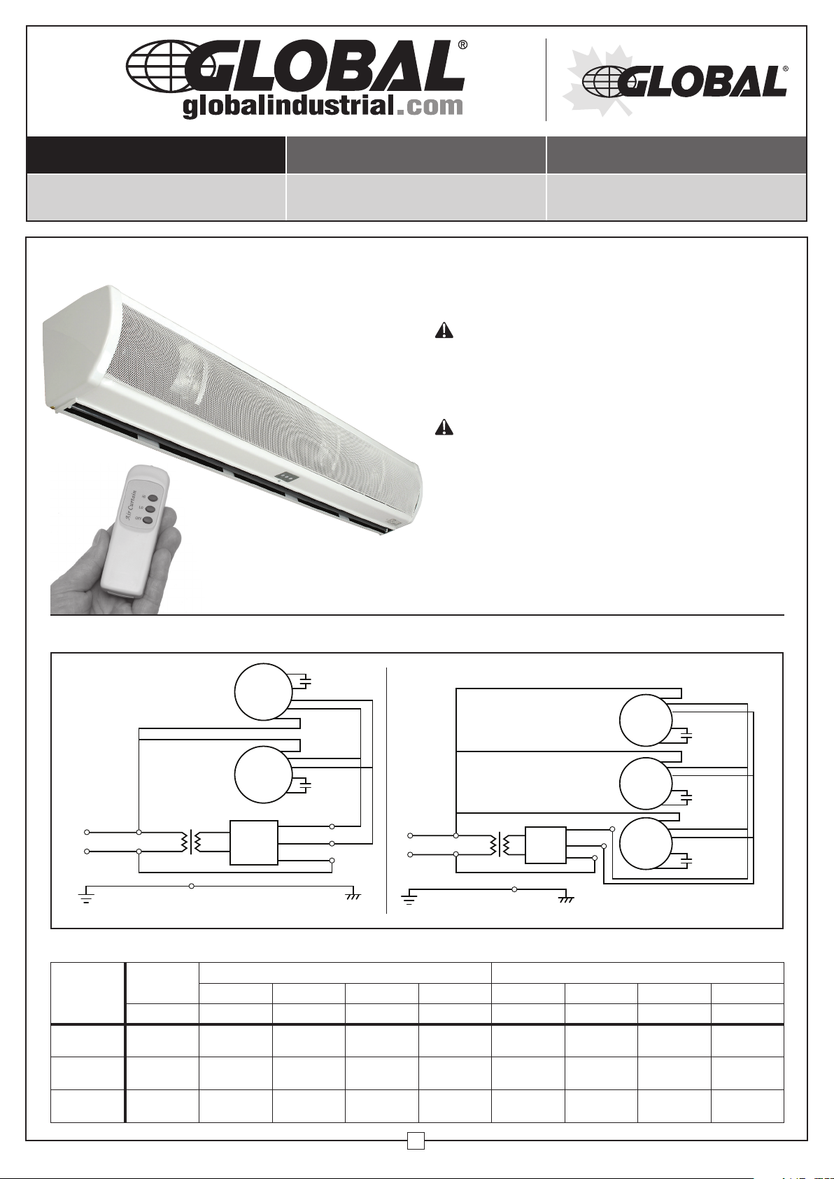
AIR CURTAIN
Models 246608, 246609 & 246610
CAUTION:
•
READ and FOLLOW all instructions prior to operating
the Air Curtain.
•
Do NOT operate the unit if any equipment is damaged
and/or missing.
WARNING:
To reduce the risk of fire or electrical shock:
• Do NOT expose the unit to moisture, water, rain, or any
other fluids.
• Do NOT use the Air Curtain in conjunction with any solid
state speed control devices.
• Do NOT use the Air Curtain in windows. Rain and moisture
may cause an electrical hazard.
• Disconnect the Air Curtain from the power source when
not in use, when relocating, or prior to maintenance/
servicing.
1. WIRING DIAGRAM
Black
Black
BlackBlue
Brown
Yellow Green
Red
Transformer
FM-1209-2 246608
FM-1212-2 246609 FM-1215-2 246610
2. SPECIFICATIONS
Model
FM-1209-2
246608
FM-1212-2
246609
FM-1215-2
246610
SIZE
INCH A W m/s DB A W m/s DB
36 2.10 255 16 56 2.85 345 20 59
48 2.65 320 16 56 3.50 425 20 59
60 3.60 440 16 56 4.80 575 20 59
MOTOR
MOTOR
Remote
Control
Receiver
Brown (Low)
Brown (Low)
Brown
White
Red
Capacitor
White (Hi)
White (Hi)
Capacitor
Blue
Brown
Yellow Green
Black
Black
Black
Red
Transformer
Remote
Control
Receiver
Brown
White
Red
MOTOR
MOTOR
MOTOR
Brown (Low)
White (Hi)
Capacitor
Brown (Low)
White (Hi)
Capacitor
Brown (Low)
White (Hi)
Capacitor
LOW HIGH
Current Power Velocity Noise Current Power Velocity Noise
1
090718
Page 2
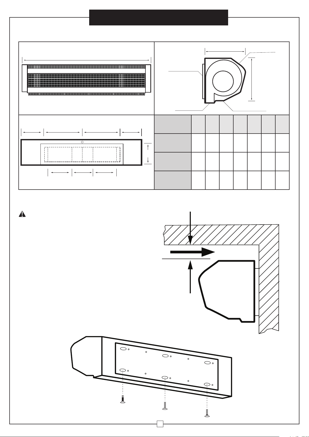
3. INSTALLATION DIMENSIONS
Instruction Manual
Air Curtain
A
B B
C
C
E E E
D
Mounting Plate
MODEL
FM-1209-2
246608
FM-1212-2
246609
FM-1215-2
246610
F
Air Inlet
G
Control SwitchAir Outlet
A B C D E F G
36 2 16 5 10 8 85/8
48 8 16 5 10 8 85/8
60 14 16 5 10 8 85/8
4. INSTALLATION METHOD
WARNING
INSTALLATION AND ELECTRICAL CONNECTIONS
MUST BE PERFORMED BY A QUALIFIED TECHNICIAN.
1) Accessories include 6 sets of (M8 x 60L) fastening
bolts, washers, spring washers, and (MS) nuts.
2) Check to ensure the voltage / frequency on the rating
label complies with the local power source prior to
use.
3) Follow the diagram (A) to reference the proper
installation position.
4) Coverage height is 99 inches for horizontal Air Curtain
installations.
5) Wall installation:
a. Remove the INSTALLATION PLATE by
unscrewing the fixing screws down the REAR of
the plate.
Diagram A
2" Above
Indoor
Outdoor
Remove screws from plate
2
Page 3
Instruction Manual
Air Curtain
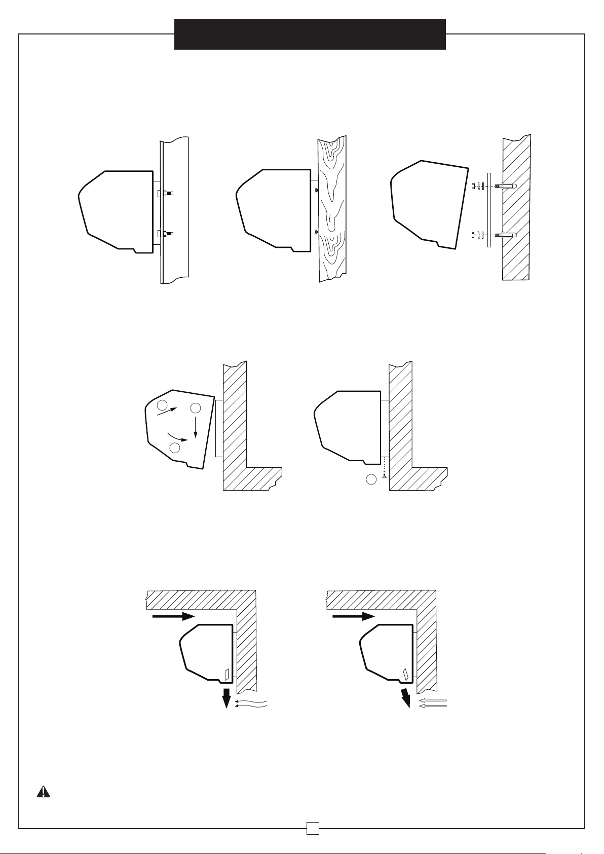
b. Mount the INSTALLATION PLATE to the wall:
• Adjust the unit position to your requirements.
• Depending on type of installation fasten the INSTALLATION PLATE to the wall using the washers, spring
washers, and nuts. See the details below.
• Ensure the INSTALLATION PLATE is secure.
Installation on Cement WallInstallation on Steel Framework Installation on Wooden Framework
c. Install the BODY by hanging it onto the INSTALLATION PLATE. Verify it is properly secured and tighten the
fixing screws. See the following diagram:
1
7) Use more than one Air Curtain unit with the appropriate length to support the width of a doorway.
8) The recommended distance between 2 adjacent units is 1-2 inches.
5. OPERATION INSTRUCTIONS
1) Plug the unit into an AC power outlet. (The OFF position is displayed with a lit lamp)
2) Select the LO or HI functions on the unit or Remote Control to regulate fan speed.
3) Adjust the AIR DEFLECTORS to direct air flow. See the following diagram:
2
3
4
6. WARNINGS AND MAINTENANCE
1) Be sure to install the unit in a stable environment for safety. Verify installation quality.
2) Do NOT install the Air Curtain within close proximity of water, high temperatures, or explosive / corrosive gases.
3) In case of malfunction or damage, a qualified technician should be contacted.
4) Ensure proper and consistent Air Curtain maintenance. (Do NOT clean the unit with benzene or other corrosive liquids)
WARNING
Unplug the power cord prior to any routine maintenance or servicing.
3
Page 4

globalindustrial.ca
User's manual Manual del usuario Manuel de l'utilisateur
Customer Service
US: 1-800-645-2986
Servicio de atención al Cliente
US: 1-800-645-2986
Service à la clientèle
Canada: 888-645-2986
CORTINA DE AIRE
Modelos 246608, 246609 & 246610
PRECAUCIÓN:
• LEA y SIGA todas las instrucciones antes de operar la
Cortina de Aire.
• NO opere la unidad si algún equipo está dañado y/o falta.
ADVERTENCIA:
Para reducir el riesgo de incendio o descarga eléctrica:
• NO exponga la unidad a la humedad, el agua, la lluvia o
cualquier otro fluido.
• NO use la Cortina de Aire junto con ningún dispositivo
de control de velocidad de estado sólido.
• NO use la Cortina de Aire en ventanas. La lluvia y la
humedad pueden ocasionar peligro de descarga eléctrica.
• Desconecte la cortina de aire de la fuente de alimentación
cuando no esté en uso, cuando sea reubicada o antes
de realizar mantenimiento y/o servicio.
1. DIAGRAMA DEL CABLEADO
Black
Black
Brown
Yellow Green
BlackBlue
Red
Transformer
Remote
Control
Receiver
FM-1209-2 246608
FM-1212-2 246609 FM-1215-2 246610
2. ESPECIFICACIONES
Model
FM-1209-2
246608
FM-1212-2
246609
FM-1215-2
246610
SIZE
Current Power Velocity Noise Current Power Velocity Noise
INCH A W m/s DB A W m/s DB
36 2.10 255 16 56 2.85 345 20 59
48 2.65 320 16 56 3.50 425 20 59
60 3.60 440 16 56 4.80 575 20 59
MOTOR
MOTOR
Brown (Low)
Brown (Low)
Brown
White
Red
Capacitor
White (Hi)
White (Hi)
Capacitor
Blue
Brown
Yellow Green
Black
Black
Black
Red
Transformer
Remote
Control
Receiver
Brown
White
Red
LOW HIGH
MOTOR
MOTOR
MOTOR
Brown (Low)
White (Hi)
Capacitor
Brown (Low)
White (Hi)
Capacitor
Brown (Low)
White (Hi)
Capacitor
1
090718
Page 5

3. DIMENSIONES DE INSTALACIÓN
Manual del usuario
CORTINA DE AIRE
A
B B
C
C
E E E
D
Placa de montaje
MODEL
FM-1209-2
246608
FM-1212-2
246609
FM-1215-2
246610
F
Entrada de aire
G
Interruptor de controlSalida de aire
A B C D E F G
36 2 16 5 10 8 85/8
48 8 16 5 10 8 85/8
60 14 16 5 10 8 85/8
4. MÉTODO DE INSTALACIÓN
ADVERTENCIA
LA INSTALACIÓN Y LAS CONEXIONES ELÉCTRICAS DEBEN
SER REALIZADAS POR UN TÉCNICO CALIFICADO.
1) Los accesorios incluyen 6 juegos de tornillos de
fijación (M8 x 60L), arandelas, arandelas de resorte y
tuercas (MS).
2) Verifique y asegúrese de que el voltaje/frecuencia en
la etiqueta de clasificación cumpla con la fuente de
alimentación local antes de dar uso al dispositivo.
3) Siga el diagrama (A) para tener referencia de la
posición de instalación adecuada.
4) La altura de cobertura es de 99 pulgadas para las
instalaciones horizontales de cortinas de aire.
5) Instalación en la pared:
a. Retire la PLACA DE INSTALACIÓN
desatornillando los tornillos de fijación en la
PARTE TRASERA de la placa.
Diagrama A
2" Por
encima
Interior
Exterior
Quite los tornillos de la placa
2
Page 6

Manual del usuario
CORTINA DE AIRE
b. Monte la PLACA DE INSTALACIÓN en la pared:
• Ajuste la posición de la unidad según sus requisitos.
• Dependiendo del tipo de instalación, fije la PLACA DE INSTALACIÓN a la pared usando las arandelas,
las arandelas de resorte y las tuercas. Vea los detalles a continuación.
• Asegúrese de que la PLACA DE INSTALACIÓN esté segura.
Instalación en pared de cementoInstalación en marco de acero Instalación en marco de madera
c. Instale el CUERPO colgándolo de la PLACA DE INSTALACIÓN. Verifique que esté bien sujeto y apriete los
tornillos de fijación. Vea el siguiente diagrama:
1
7) Use más de una unidad de Cortina de Aire con la longitud adecuada para cubrir el ancho de una puerta.
8) La distancia recomendada entre 2 unidades adyacentes es de 1 a 2 pulgadas.
5. INSTRUCCIONES DE OPERACIÓN
1) Enchufe la unidad en una toma de corriente de CA (la posición APAGADO se muestra con una lámpara encendida)
2) Seleccione las funciones LO o HI en la unidad o en el control remoto para regular la velocidad del ventilador.
3) Ajuste los DEFLECTORES DE AIRE para dirigir el flujo de aire. Vea el siguiente diagrama:
2
3
4
6. ADVERTENCIAS Y MANTENIMIENTO
1) Asegúrese de instalar la unidad en un entorno estable por motivos seguridad. Verifique la calidad de la instalación.
2) NO instale la cortina de aire cerca de agua, altas temperaturas o gases explosivos y/o corrosivos.
3) En caso de mal funcionamiento o avería, debe contactar a un técnico calificado.
4)
Asegure un mantenimiento adecuado y constante de la cortina de aire. (NO limpie la unidad con benceno u otros líquidos corrosivos)
ADVERTENCIA
Desenchufe el cable de alimentación antes de realizar cualquier mantenimiento de rutina.
3
Page 7

globalindustrial.ca
User's manual Manual del usuario Manuel de l'utilisateur
Customer Service
US: 1-800-645-2986
Servicio de atención al Cliente
US: 1-800-645-2986
Service à la clientèle
Canada: 888-645-2986
RIDEAU D'AIR
Modèles 246608, 246609 & 246610
ATTENTION :
• LISEZ et SUIVEZ toutes les instructions avant d’utiliser
le rideau d’air.
• N'UTILISEZ PAS l'appareil si un élément est endommagé
et/ou manquant.
AVERTISSEMENT :
• Pour réduire les risques d’incendie ou de choc électrique :
• N'exposez PAS l'appareil à l'humidité, à l'eau, à la pluie
ou à tout autre liquide.
• N'utilisez PAS le rideau d'air conjointement avec des
dispositifs de contrôle de vitesse à semi-conducteurs.
• N'utilisez PAS le rideau d'air pour des fenêtres. La pluie
et l'humidité peuvent causer un risque électrique.
• Débranchez le rideau d'air de la source d'alimentation
lorsqu'il n'est pas utilisé, lors du déplacement ou avant
la maintenance ou l'entretien.
1. SCHÉMA DE CÂBLAGE
Black
Black
BlackBlue
Brown
Yellow Green
Red
Transformer
FM-1209-2 246608
FM-1212-2 246609 FM-1215-2 246610
2. Spécifications
Model
FM-1209-2
246608
FM-1212-2
246609
FM-1215-2
246610
SIZE
INCH A W m/s DB A W m/s DB
36 2.10 255 16 56 2.85 345 20 59
48 2.65 320 16 56 3.50 425 20 59
60 3.60 440 16 56 4.80 575 20 59
MOTOR
MOTOR
Remote
Control
Receiver
Brown (Low)
Brown (Low)
Brown
White
Red
Capacitor
White (Hi)
White (Hi)
Capacitor
Blue
Brown
Yellow Green
Black
Black
Black
Red
Transformer
Remote
Control
Receiver
Brown
White
Red
MOTOR
MOTOR
MOTOR
Brown (Low)
White (Hi)
Capacitor
Brown (Low)
White (Hi)
Capacitor
Brown (Low)
White (Hi)
Capacitor
LOW HIGH
Current Power Velocity Noise Current Power Velocity Noise
1
090718
Page 8

3. DIMENSIONS D'INSTALLATION
RIDEAU D'AIR
Manuel de l'utilisateur
A
B B
C
C
E E E
D
Support
MODEL
FM-1209-2
246608
FM-1212-2
246609
FM-1215-2
246610
F
Entrée d'air
G
Molette de commandeSortie d'air
A B C D E F G
36 2 16 5 10 8 85/8
48 8 16 5 10 8 85/8
60 14 16 5 10 8 85/8
4. MÉTHODE D'INSTALLATION
AVERTISSEMENT
L'INSTALLATION ET LES CONNEXIONS ÉLECTRIQUES
DOIVENT ÊTRE EFFECTUÉES PAR UN TECHNICIEN QUALIFIÉ.
1) Les accessoires comprennent 6 jeux de boulons de
fixation (M8 x 60L), rondelles, rondelles Grower et
écrous (MS).
2) Vérifiez que la tension/fréquence indiquée sur
l’étiquette d’alignement est conforme à la source
d’alimentation locale avant utilisation.
3) Suivez le diagramme (A) pour déterminer la position
d’installation appropriée.
4) La hauteur de couverture est de 2,5 mètres pour les
installations de rideau d'air horizontales.
5) Installation murale :
a. Retirez la PLAQUE D'INSTALLATION en
dévissant les vis de fixation de la partie
ARRIÈRE de la plaque.
Diagramme A
2''
ci-dessus
Intérieur
Extérieur
Retirer les vis de la plaque
2
Page 9

Manuel de l'utilisateur
RIDEAU D'AIR
b. Fixez la PLAQUE D'INSTALLATION au mur :
• Ajustez la position de l'unité à vos besoins.
• Selon le type d'installation, fixez la PLAQUE D'INSTALLATION au mur à l'aide des rondelles, des rondelles
Grower et des écrous. Voir détails ci-dessous.
• Assurez-vous que la PLAQUE D'INSTALLATION est bien fixée.
Installation sur un mur de cimentInstallation sur cadre en acier Installation sur cadre en bois
c. Installez le CORPS en le suspendant à la PLAQUE D'INSTALLATION. Vérifiez qu'il est correctement fixé et
serrez les vis de fixation. Voir le diagramme ci-dessous :
1
7) Utilisez plusieurs rideaux d'air avec la longueur appropriée pour couvrir toute la largeur d'une porte.
8) La distance recommandée entre 2 unités adjacentes est de 2,5 à 5 cm.
5. INSTRUCTIONS D'UTILISATION
1) Branchez l’appareil sur une prise secteur. (La position OFF est indiquée par un voyant allumé)
2) Sélectionnez les fonctions LO (lent) ou HI (rapide) de l'appareil ou de la télécommande pour régler la vitesse du ventilateur.
3) Ajustez les déflecteurs pour diriger le flux d’air. Voir le diagramme ci-dessous :
2
3
4
6. MISES EN GARDE ET ENTRETIEN
1)
Pour des raisons de sécurité, assurez-vous d'installer l'unité dans un environnement stable. Vérifiez la qualité de l'installation.
2)
N'installez PAS le rideau d'air à proximité d'eau, dans un endroit exposé à des températures élevées ou à des gaz explosifs ou corrosifs.
3)
En cas de dysfonctionnement ou de panne, contactez un technicien qualifié.
4)
Assurer un entretien correct et régulier du rideau d’air. (NE nettoyez PAS l'appareil avec du benzène ou d'autres liquides corrosifs)
AVERTISSEMENT
Débranchez le cordon d'alimentation avant toute opération d'entretien ou de maintenance de routine.
3
 Loading...