

Global Industrial 246110 Assembly Instructions Manual

WALL THERMOSTAT
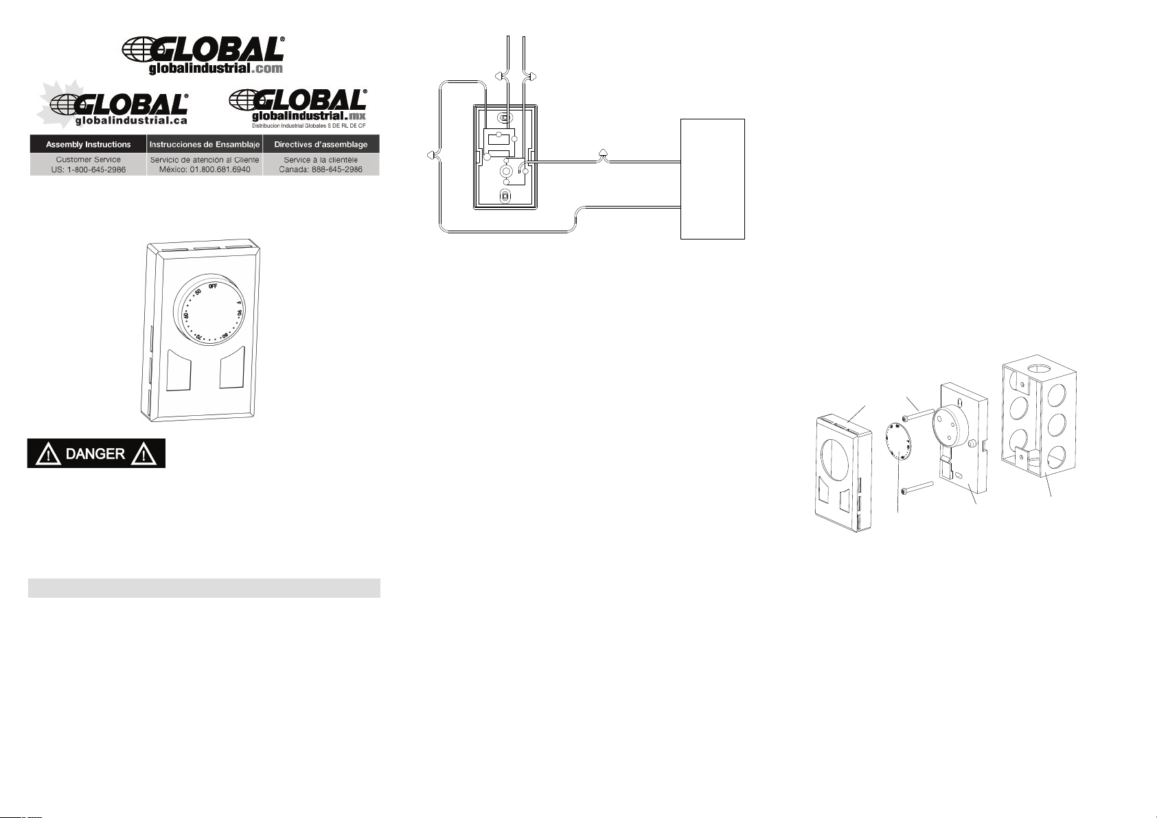
L1 from
power supply
Neutral from
power supply
Line
Red
Load
Black
Thermostat
Wire Connector
Heater
Cover
Screw
Index Plate
Base
Outlet Box
Model: 246110
READ ALL WIRE SIZING, VOLTAGE REQUIREMENTS AND SAFETY DATA TO
AVOID PROPERTY DAMAGE AND PERSONAL INJURY OR ELECTRIC SHOCK.
READ CAREFULLY - These instructions will help prevent difficul-
ties that might arise during thermostat installation.Studying the instructions first may save considerable time and money later.Observing the
following procedures will keep installation time to a minimum.Save these
instructions for future use.
READ AND SAVE THESE INSTRUCTIONS
Double Pole Thermostat Installation
1. Disconnect power supply to prevent electrical shock or
damage to product.
2. Run line voltage wiring to the thermostat location.
3.a) Connect the LOAD BLACK wire from the thermostat to
the one of wires from the heating unit.
b) Connect another black wire from the thermostat to
another wire from the heating unit.
4.a) Connect the LINE RED wire on the thermostat to the
b) Connect another red wire from the thermostat to
L1 line from the supply panel.
another wire from the supply panel.
5. Make sure all connections are tight.
6. Insert wires into the junction box, making sure not to
damage wiring.
7.Secure the ground wire to the ground screw provided in
junction box.
8.Remove the thermostat cover by grabbing the cover from
the sides and pulling it away from base.
9. Mount the thermostat into the junction box and secure
using the provided screws.
10. Replace thermostat cover.
The installation of the thermostat must comply with the applicable local and/or national electrical code and utility requirements. This installation should be performed by a
qualified electrician where required by law. Ensure that all
wiring connections to the thermostat are correct and tight to
prevent electrical shorts. Use the appropriate wire to meet
local and national electrical codes for rated power consumption.
Product Setup and Settings
To adjust the temperature to your requirements, turn the dial
on the thermostat clockwise all the way to turn heater on.
When the room reaches the desired temperature, turn the
thermostat knob counter clockwise until you hear the click.
Leave in this position to maintain the room temperature at
this setting. For additional heat, turn clockwise until you
hear the click and the heater will turn on.
- Turning knob fully counter clockwise will disconnect the
power to the heater.
Changing °C and °F control dials.
Use a small flathead screwdriver to pry off the control dial.
Insert into one of the slots on the dial and gentle apply pressure to remove.To install the new control dial, line up the
pins on the dial with the holes on the thermostat knob. Push
together until secured into place.
Thermostat is compatible with electric heaters and electric
Specifications:
garage heaters
Power Supply AC 120V / 208V / 240V / 277V Maximum
Power:
3360W @ 120VAC (28A)
5824W @ 208VAC (28A)
6720W @ 240VAC (28A)
7756W @ 277VAC (28A)
Sensing Element: Bimetal Temperature Operating Range:
41°F-90°F (5°C -32°C)
cETLus listing.
Functions And Features
• 120/208/240/277 Volts
•Includes both ºC and ºF control dials
•Wall mount design– Sits flush against wall
•Double Pole – provides positive OFF position
•Disconnects power for extra protection
•Large knob allows easy adjustment to all temperatures
•90°F (32°C) maximum setting
Installation Instructions
Warning: Turn OFF the power at the circuit breaker before
installing. Installation should be performed by a qualified
electrician.
Refer to thermostat and heater load specifications before
installation of the thermostat to see if it can handle the
amp load. The maximum this thermostat can run is 7756
Watts at 277 Volts, 6720 Watts at 240 Volts, 5824 Watts at
208 Volts and 3360 Watts at 120 Volts.
Install unit in a grounded metal or plastic wall junction box,
indoors 4 ½’ to 5’ above the floor. Avoid any area where it
can come in to contact with external sources of heat and
cold. This includes plumbing pipes, direct sunlight, a T.V.
set, lamps, and drafts from a door or window, as this may
cause inaccurate temperature readings. The most convenient place is above the light switch. Not for outdoor use.
THERMOSTAT MURAL
L1 de
L'alimentation
Électrique
Neutre de
L'alimentation
Électrique
Ligne
Rouge
Charger
Noire
Thermostat
Wire Connecteur
Chauffage
Couvrir
Visser
Index des tôles
Base
Outlet Box
Modèles: 246110
VEUILLEZ RESPECTER LES DIRECTIVES DE
SÉCURITÉ ET LES EXIGENCES RELATIVES
AU CÂBLAGE ET À LA TENSION AFIN
D’ÉVITER LES RISQUES DE DOMMAGES
MATÉRIELS, DE DÉCHARGE ÉLECTRIQUE
OU DE BLESSURES PERSONNELLES.
VEUILLEZ LIRE ATTENTIVEMENT - Les présentes instruc-
tions vous aideront à éviter certaines difficultés qui pourraient survenir
au moment de l’installation. Prenez connaissance des instructions avant
de commencer l’installation, afin d’éviter les pertes de temps et d’argent.
Vous minimiserez le temps d’installation requis en suivant les procédures indiquées dans le présent guide. Conservez ces instructions pour
usage ultérieur.
CONSERVES CES INSTRUCTIONS
Installation Du Thermostat Bipolaire
1. Co
u
pez l’alimentatio
décharges électriques ou les dommages à l’appareil.
2. Faites passer le fil de tension secteur jusqu’à l’emplacement
3.a) Connecter la charge noir du thermostat de l'un des fils
de l'unité de chauffage
b) Connectez l'autre fil noir du thermostat d'un câble de
l'unité de chauffage
4.a) Connectez ligne fil rouge sur le thermostat pour le
groupe de l'approvisionnement en L1.
b) Connectez l'autre fil rouge du thermostat d'un câble de
la fourniture d'experts.
du thermostat.
n électriqu
e
afin de prévenir les
5. Vérifiez que toutes les connexions sont serrées.
6. Insérez les fils dans la boîte de jonction en veillant à
ne pas les endommager.
7. Fixez le fil de mise à la terre à la vis de terre dans la
boîte de jonction.
8 .Retirez le couvercle du thermostat en l’agrippant sur les
côtés et en le tirant gors de la base.
9. Posez le thermostat dans la boîte de jonction et fixez-le
en place à l’aide des vis fournies.
10. Remettez le couvercle du thermostat en plcae.
L’installation de ce thermostat doit respecter les exigences du
fournisseur de services publices ainsi que les normes d’électricité locales et nationales. L’installation doit être effectuêtrée par
un électricien qualifié là où la loi l’exige. Vérifiez que tous les
branchements électriques au thermostat sont corrects et bien
serrés pour éviter les risques de courts-circuits. Utilisez le
câblage approprié à la consommation électrique de l’appareil,
afin de respecter les normes d’électricité locales et nationales.
Péglage Et Paramètres Du Thermostat
Pour ajuster la température ambiante, tournez le cadran du
thermostat dans le sens horaire jusqu’au bout, afin de mettre
l’appareil de chauffage en marche. Lorsque la température ambiante atteint le niveau désiré, tournez le cadran du thermostat
dans le sens antihoraire jusqu’à ce que vous entendiez un clic.
Laissez le thermostat à ce réglage pour maintenir la température ambiante. Pour réchauffer la pièce,tournez le cadran du
thermostat jusqu’à ce que vous entendiez un clic, l’appareil de
chauffer se metta alors en marche.
- Pour arrêter complètement l’appareil de chauffage, tournez le
cadran du thermostat dans le sens antihoraire, jusqu’au bout.
Pour changer les cadrans de réglage en °C et en °F.
Utilisez un petit tournevis à tête plate pour retirer le cadran. Insérez le tournevis dans l’une des fentes du cadran et retirez
celui-ci en appliquant une légère pression. Pour installer l’autre
cadran, faites correspondre les tiges du cadran avec les ouvertures dans le bouton du thermostat. Poussez le cadran jusqu’à
ce qu’il soit bien fixé en place.
Le thermostat est compatible avec les appareils de chauffage
Spécifications
électriques et les radiateurs pour garge.
Alimentation électrique: AC 120V / 208V / 240V / 277V
Puissance maximale:
3360W @ 120VAC (28A)
5824W @ 208VAC (28A)
6720W @ 240VAC (28A)
7756W @ 277VAC (28A)
Élément de détection bimétallique Gamme de température de
fonctionnement: 41°F à 90°F (5°C -32°C)
Homologué cETLus.
Fonctions Et Caractéristiques
• 120/208/240/277 Volts
•Cadrans de réglage en ºC et ºF inclus
•Installation murale – posé à plat contre le mur
•Bipolaire – fournit une position d’arrêt positif
•Coupe l’alimentation pour une protection supplémentaire
•Grand bouton pour un ajustement facile à toutes les températures
•Réglage maximal de 90°F (32°C)
Directives D’installation
Avertissement: Coupez l’alimentation électrique au panneau élec-
trique principal avant de commencer l’installation. L’installation devrait être effectuée par un électricien qualifié. Consultez les
spécifications électriques du thermostat et de I’appareil de
chauffage avant d’installer le thermostat, afin de vérifier que celui-ci
pourra bien supporter la charge. La puissance maximale pouvant
être acceptée par ce thermostat est : 7756 Watts à 277 Volts, 6720
Watts à 240 Volts, 5824 Watts à 208 Volts ou 3360 Watts à 120
Volts.
Installez le thermostat dans une boîte de jonction en métal ou en
plastique avec mise à la terre, dans un endroit à l’intérieur, à 4 ½’
ou 5 pieds au-dessus de sol. Évitez les endroits où le thermostat
pourrait entrer en contact avec des sources de chaud ou de froid,
incluant les tuyaux de plomberie, l’ensoleillement direct, un
téléviseur, une lampe ou une brise provenant d’une fenêtre ou
d’une porte ouverte; ceci pourrait fausser la lecture de la température. ll est recommandé d’installer le thermostat au-dessus de l’interrupteur mural. Le thermostat ne doit pas être installé à l’extérieur.
 Loading...