

Page 1
Blower HeElectric
Models: 653561 653560 6535
653558 653562 246067
g
globalindustrial.ca
Assembly Instructions Instrucciones de Ensambla
Customer Service
US: 1-800-645-2986
Servicio de atención al Clien
México: 01.800.681.6940
DE CFDistribucion Industrial Globales S DE RL
ectives d’assemblageDir
Service à la clientèle
Canada: 888-645-2986
THESE
050117
1
READ & SAVE
INSTRUCTIO
Wall Mount Models: 653566 653567 653568
653569 246068
READ & SAVE THESE
INSTRUCTIONS
Models: 246103, 246104, 246132, 246133 ,
246134, 246725 & 246727
Vertical or Horizontal Downflow
Unit Heater
Page 2
Vertical or Horizontal Downflow Unit Heater
User’s Manual
2
IMPORTANT INSTRUCTIONS
When using electrical appliances, basic precautions should
always be followed to reduce risk of fire, electrical shock and
injury to persons or property, including the following:
Please read all instructions before using this heater.
NOTE: This product must be installed by a certified electrician
in accordance with local codes.
Traces of smoke or odor when unit is initiated indicates that small
amounts of oil leaked on heating coil during manufacturing. It will
evaporate quickly and should not re-occur. Make sure the appliance location is well ventilated during operation. It is normal for the
unit to emit sounds when turned on for the first time.
Make sure that the room in which the appliance is located is well
ventilated during this operation.
1.Read all instructions before using this heater.
2.This heater is hot when in use. To avoid burns, do not let
bare skin touch hot surfaces. Keep combustible materials,
such as furniture, pillows, bedding, papers, clothes and
curtains at least 3 ft. (0.9 meters) from the front and top of the
heater and keep them away from the sides and rear.
3.Extreme caution and reasonable supervision is necessary
when any heater is used by or near children, invalids or pets
and whenever the heater is left operating and unattended.
4. Always switch off the heater when not in use.
5. Do not operate any heater after the heater malfunctions, has
been dropped or damaged in any manner. Disconnect power
at service panel and have heater inspected by a qualified
electrician before reusing.
6. Do not use outdoors.
7. To disconnect heater, turn off power to heater circuit at main
disconnect panel.
8.Do not install less than 6 feet (1.8 m) high from the floor.
9.Do not insert or allow foreign objects to enter any ventilation or
exhaust opening as this may cause an electric shock or fire, or
damage the heater.
10.To prevent a possible fire, do not block air intakes or exhaust
in any manner.
11.A heater has hot and arcing or sparking parts inside. To reduce
the risk of fire, do not use it in areas where gasoline, paint, or
flammable vapors and liquids are used or stored.
12.Use this heater only as described in this manual. Any other use
not recommended by the manufacturer may cause fire, electric
shock, or injury to persons.
13. Do not install closer than 1 foot (0.3 m) from both sides and
rear of heater to any adjacent surface/wall.
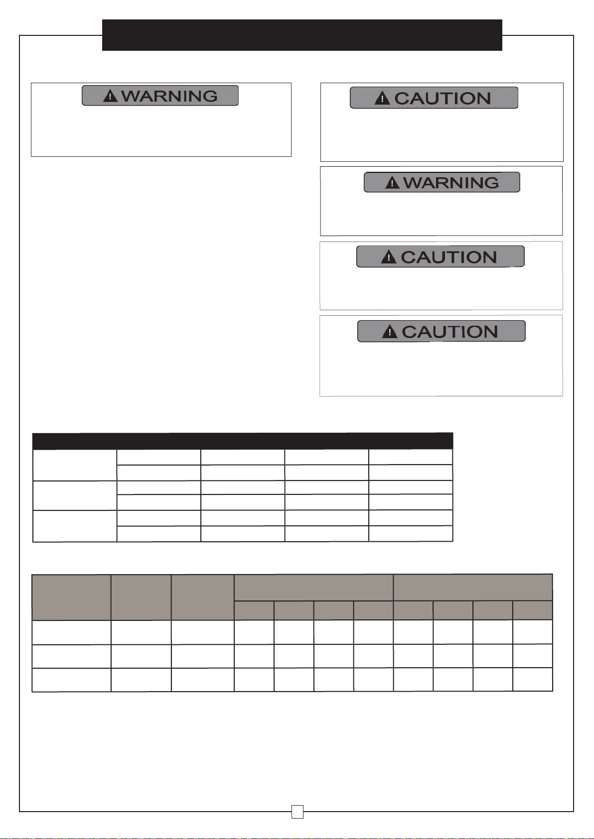
High temperature, risk of fire, keep electrical
cords, drapery, furnishings, and other
combustibles at least 3 feet (0.9 m) from the
front of the heater and away from the side
and rear.
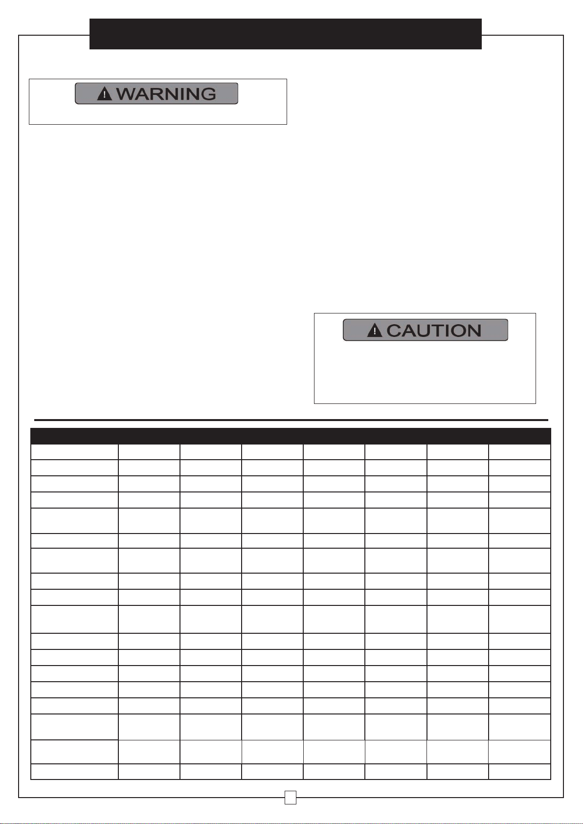
Product Specifications
Model
246725 246132
246104
246133
246103
246134 246727
Length Inches
8
1/2
8
1/2
8
1/2
8
1/2
8
1/2
13
3/4
13
13/16
Width Inches 14 19 19 19 19 19 19
1/4
Height Inches 16 21
7/16
21
7/16
21
7/16
21
7/16
21
7/16
21
1/2
Wire Size For
Installation
14AWG 8AWG 14AWG 6AWG 14AWG 12AWG 10AWG
Net Weight Lbs
28 41
41
41
41
58 64.8
Construction Cold Rolled
Steel
Cold Rolled
Steel
Cold Rolled
Steel
Cold Rolled
Steel
Cold Rolled
Steel
Cold Rolled
Steel
Cold Rolled
Steel
Btu High
17,000 25,600/19,100
25,600
34,100/25,600
34,100
51,200 68,200
Cfm High
350 650
650
650
650
910 1320
Outlet Air Tempera-
ture
150°F @ Ambient Temp. 77°F
140°F @ Ambient Temp. 77°F
140°F @ Ambient Temp. 77°F
149°F @ Ambient Temp. 77°F
149°F @ Ambient Temp. 77°F
152°F @ Ambient Temp. 77°F
160°F @ Ambient Temp. 77°F
Voltage
480 208/240
480
208/240
480
480 480
Phase
3 1or3
3
1or3
3
33
Amps
6 31.3/27
9
42/36
12
18 24
Watts
5,000 5,600/7,500
7,500
7,500/10,000
10,000
15,000 20,000
Kilowatts
5 5.6/7.5
7.5
7.5/10
10
15 20
Circuit Breaker Amp
rating
20A 40A 15A 55A 15A 25A 30A
Limited Warranty
Years
1111111
Certification
UL/cUL UL/cUL UL/cUL UL/cUL UL/cUL UL/cUL UL/cUL
Page 3
User’s Manual
3
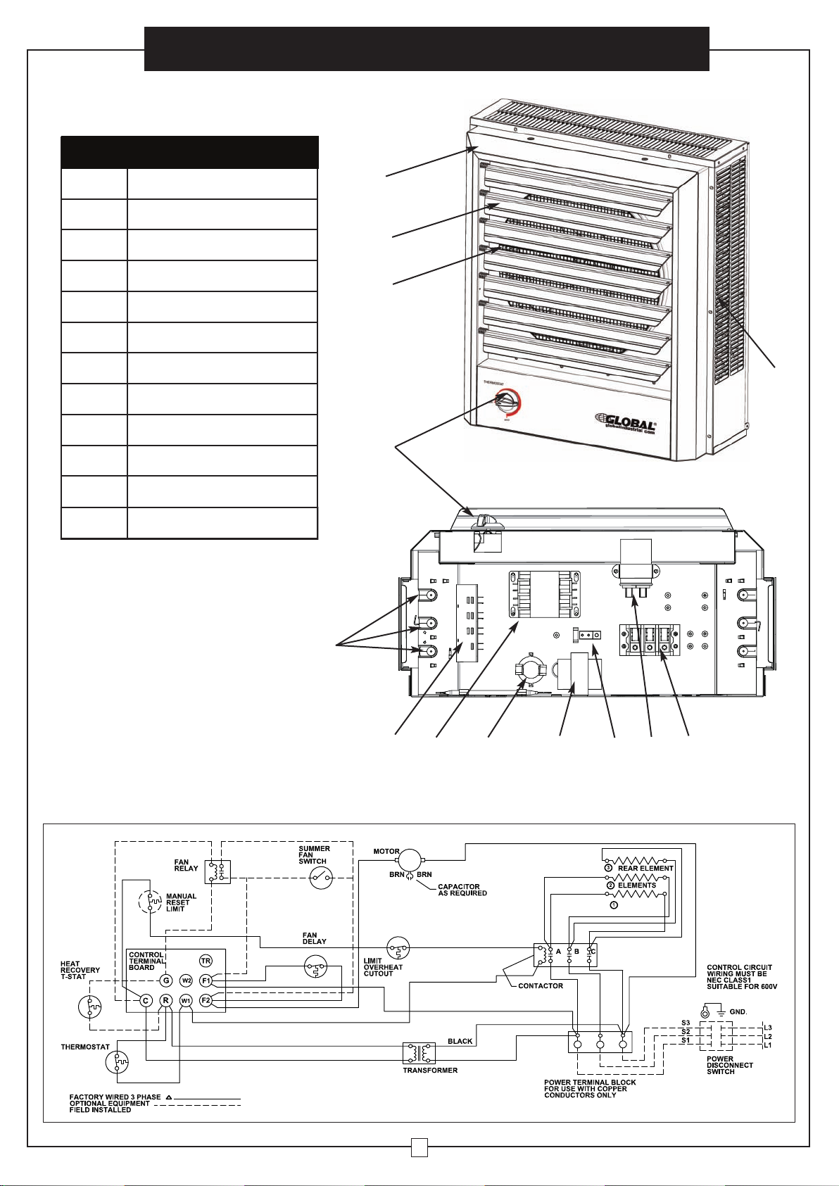
Wiring Diagram for 246103 & 246104
A
B
C
FG I JK
D
H
E
D
A Housing
B Louver
C Front Exhaust Grill
D Heating Element
E Thermostat Knob
F Wiring Board
G Contactor
H Linear Limit Protector
I Transformer
J Ground Lug
K Capacitor
L Terminal Block-Power
Parts List
PARTS OF THE HEATER
Vertical or Horizontal Downflow Unit Heater
L
Page 4
User’s Manual
4
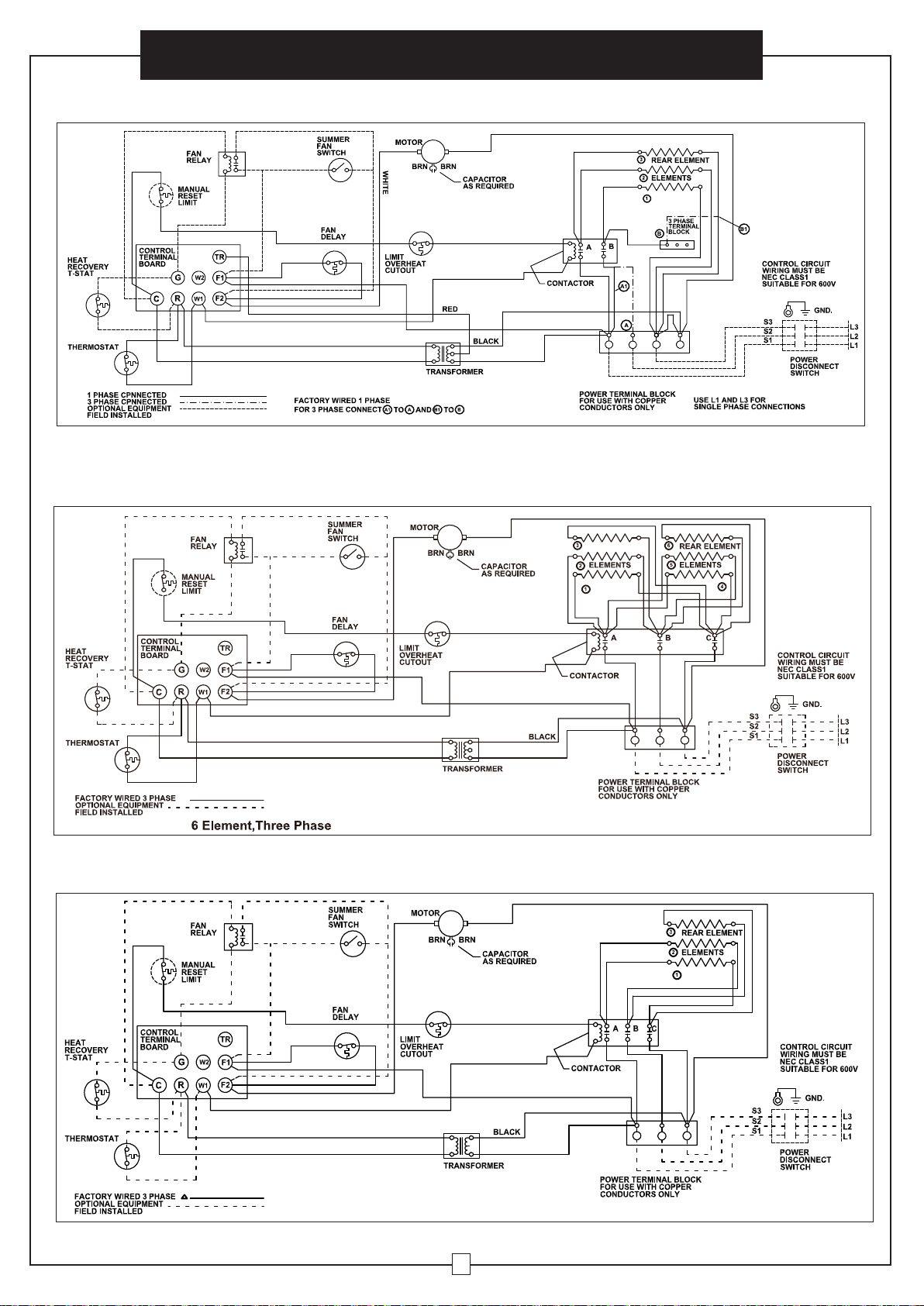
Wiring Diagram for 246132 & 246133
Wiring Diagram for 246134 & 246727
Vertical or Horizontal Downflow Unit Heater
Wiring Diagram for 246725
Page 5
User’s Manual
5
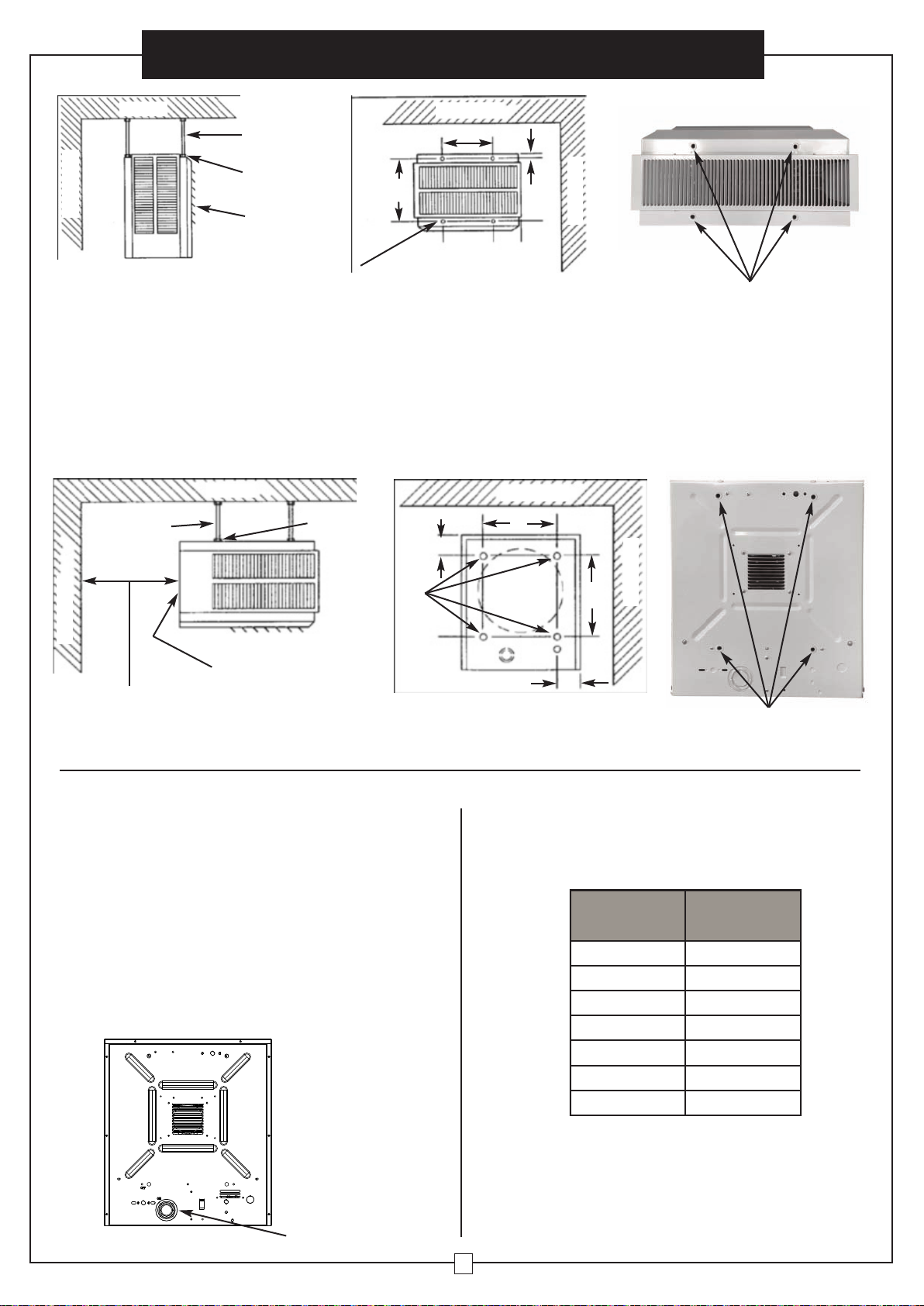
Table 1 -Wall and Ceiling Clearance, inches(mm) / Mounting
Brackets
MOUNTING
Model
Discharge
Ceiling
Side Wall
Back Wall
246103,246104,
246132,246133
Horizontal
6” (152.4)
6” (152.4)
13” (330.2)
Vertical
6” (152.4)
24” (609.6)
24” (609.6)
246134,246727
Horizontal 6” (152.4)
9” (228.6)
12 1/2” (330.2)
Vertical 6” (152.4)
24” (609.6)
24” (609.6)
246725
Horizontal
2” (50.8)
6” (152.4)
9” (228.6)
Vertical
6” (152.4)
18” (457.2)
18” (457.2)
Table 2 - Mounting Rod Spacing
ROD MOUNTING
HORIZONTAL DISCHARGE
NOTE: Mounting rods not included. Mounting rods need to contain a 5/16”-18 thread size and must be a minimum of 7.5” long.
1.Remove the four bolts from the threaded holes on the top of the heater.
2. Install four threaded mounting rods (not included) in the threaded holes of the heater and secure in place using lock nuts.
3. Securely attach the four mounting rods to the ceiling.
Refer to Table 1 for wall and ceiling clearances and Table 2 for mounting rod spacing.
Model
Rod
Thread
Type
Rod
Length
Horizontal
(Figure 1)
Vertical
(Figure 2)
A
B
C
D
E
F
G
H
246103,246104,
246132,246133
5/16-18
at least 10”
6
1
/16”
8
7
/8”
5
1
/8”
3/4”
8
7
/8”
14
5
/8”
2”
5
1
/8”
246134,246727
5/16-18
at least 10”
11
3
/8”
8
7
/8”
5
1
/8”
3/4”
8
7
/8”
14
5
/8”
2”
5
1
/8”
246725
5/16-18
at least 10”
6
1
/16”
6” 4
1
/16”
3/4”
6”
9
3
/4”
2”
4
3
/16”
Vertical or Horizontal Downflow Unit Heater
INSTALLING INSTRUCTIONS
All wiring must be installed by a certified electrician
according to the local electrical codes. The ceiling
heater must be grounded in accordance with all
national and local building codes.
High temperature, risk of fire, keep electrical
cords, drapery, furnishings, and other
combustibles at least 3 feet (0.9 m) from the front
of the heater and away from the side and rear.
To reduce the risk of fire, do not store or use
gasoline or other flammable vapors and
liquids in the vicinity of the heater.
All wiring procedures and connections shall be in accordance
with the national and local codes having jurisdiction.
Before installation:
Disconnect the main supply connection.
The heater must be connected to individual branch circuit.
Installation location:
1.Arrange units so their discharge air streams are subjected to a
minimum of interference from columns and partitions.
2.Direct air stream away from room occupants.
3.Do not blow air steam directly at wall.
4.Direct air stream along the windward side of a room when
installed in a building exposed to a prevailing wind.
5.If using a remote thermostat, locate thermostat approximately 5
feet above partition walls or posts away from cold drafts, internal
heat sources, and away from heater discharge air streams.
6.Large rooms require multi-unit installations. Arrange units to
provide perimeter air circulation where each unit supports the air
stream from another.
Mount the heater at least 6 feet above the floor
to prevent accidental contact with the fan blade
which could cause injury.
To prevent possible over heating or damage due
to overheating, keep at least a 5 feet clearance
in front of the heater. Refer to Table 1 for side,
top and back clearance requirements.
Page 6
User’s Manual
6
BRANCH CIRCUIT (POWER)
1. Connect heater only to the voltage, amperage and
frequency specified on the nameplate.
2. Field wiring must be properly sized to carry the amperage
in accordance with the NEC.
3. The access door is hinged. There are either one or two
screws accessible from the bottom that must be removed
to gain access.
4. A knockout is provided in the back of the heater close to
the power terminal board. The control terminal board
knockout is 1/2 inch conduit size. The power terminal
block knockout is multiple diameter. Use the diameter that
fits the required conduit size.
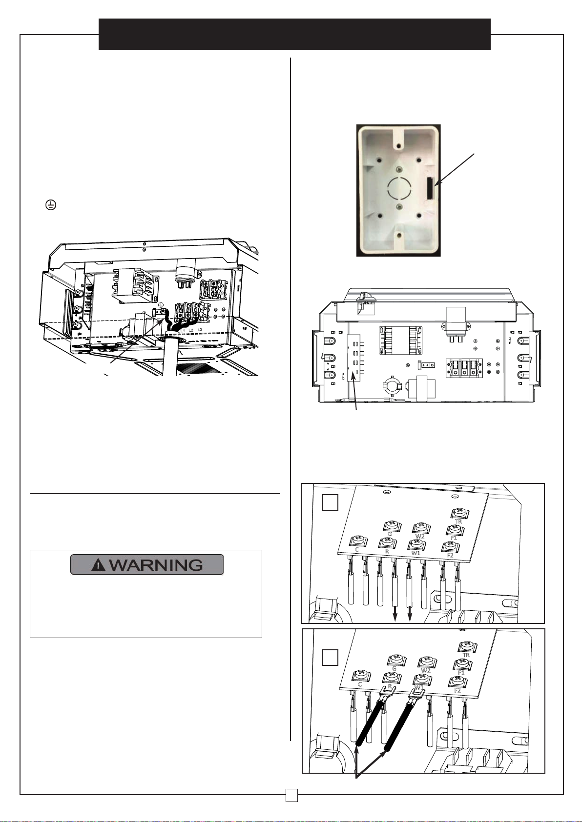
5. A ground terminal is provided near the power terminal
board. The ground wire should be connected before other
connections are made. The ground wire of model as
below.
knockout here
Side Wall
Back Wall
Threaded
Mounting
Holes(4)
E
G
F
H
WIRING INSTRUCTIONS
NOTE: Mounting rods not included. Mounting rods need to contain a 5/16”-18 thread size and must be a minimum of 7.5” long.
1.Remove the four bolts from the threaded holes on the back of the heater.
2. Install four threaded mounting rods (not included) in the threaded holes of the heater and secure in place using lock nuts.
3. Securely attach the four mounting rods to the ceiling.
Refer to Table 1 for wall and ceiling clearances and Table 2 for mounting rod spacing.
Ceiling
Back Wall
Mounting
Rod(4) - not
included
Lock Nut
Access Door
Clearance Equal to Depth of Heater to
Permit Full Opening of The Access Door
Threaded Mounting Holes(4)
for Vertical discharge
Figure 2 - Vertical Discharge Mounting and Spacing
VERTICAL DISCHARGE
Threaded Mounting Holes(4)
for Horizontal discharge
Ceiling
Back Wall
Mounting
Rod(4) - not
included
Lock Nut
Unit Heater
7” Min. Clearance to Floor
Back Wall
Side Wall
Threaded Mounting
Holes(4)
B
A
D
C
Figure 1 - Horizontal Discharge Mounting and Spacing
Model
Grounding wire
AWG#
246103 14
246104 14
246132 8
246133 6
246134 12
246725 14
246727 10
Vertical or Horizontal Downflow Unit Heater
6. The power terminal board is equipped with box terminals
sized to accept the correct size power supply wire. Wire
rated at 600V and 194°F is satisfactory for the heater
branch circuit. Copper wire is satisfactory for connection
to the heater power terminal board box terminal.
Page 7
User’s Manual
7
Vertical or Horizontal Downflow Unit Heater
7. Each heater has a wiring diagram affixed to the inside of
the access door. Consult this diagram before making any
field connections.
8. Electrical Accessories, either kits or factory-installed
options, are shown connected by a dashed line on the
heater wiring diagram.
9. Single or three-phase connections may be used with
heater models 246132 and 246133.
These units are
factory wired for single phase operation. If these heaters
are for use with three-phase power, reconnect the wires
as indicated in the wiring diagram attached to the heater.
CONTROL WIRING OF OPTIONAL
EQUIPMENT
Line voltage is present on some of the
terminals on the control terminal board.
Always disconnect the power from the heater
before making any connections to the control
board to prevent hazards.
1. Use min. 600 volt, NEC Class 1 insulated wire for all control
circuit wiring.
2. Use a crimp-on type fork terminal on the wire ends that
attach to the control terminal board if more than one
connection is to be made under the terminal screw.
3. Control wiring must be rated minimum 18 AWG.
NOTE: Thermostat and control circuit wiring must be
suitable to handle the full load of the heater
L1
L2
L3
Ground Wire
10. Connect the red live wire to L1, black live wire to L2 and
white live wire to L3 of the connector. Connect ground wire
to .
L1: red live wire L2: black live wire L3: white live wire
11.For model 246132 and 246133, the heaters are wired for
240V from factory. When heater is to be connected to
208V supply, the transformer leads have to be inter
changed. Inter change transformer red and black primary
leads (see wiring diagram on heater door). The color lead
is the COMMON for the 40VA control transformer
provided with these heaters.
How to install Wall Thermostat. (246110 Not
Included.)
1.Install Thermostat Outlet Box to the wall. Open the knock-out
on the right. Run line voltage wires to the thermostat location
via the knock-out.
knock-out here
2.Open the bottom cover (wire connection cover), at the
corner is the wiring board. This is wiring board.
wiring board
3.For model 246103 246104 246132 246133 246134 and 246727,
pull out two brown wires carefully. Lossen the screw R and
screw W1, insert two lead wires with U-Type Wire Connector
Electrical Crimp Terminal (not included) to the screw R and
screw W1, and tighten the screws.
wiring board
pull out
insert (not included)
1
2
C
yellow
red
G
R
yellow
brown
brown
W1
W2
blue
F2
black
TR
F1
orange
F2
black
TR
F1
orange
G
W2
C
yellow
red
Red
Lead
Wire
R
yellow
W1
blue
Black
Lead
Wire
Page 8
User’s Manual
8
Vertical or Horizontal Downflow Unit Heater
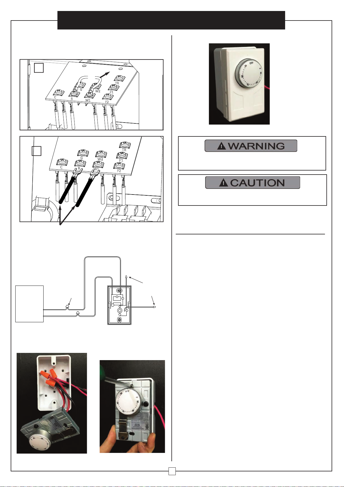
5. Connect the other side of the two lead wires to the wall
THERMOSTAT as below image:
)
6.Insert wires into the Thermostat Outlet Box, and screw up the
thermostat.
7.Cover the thermostat.
TR
F1
W2
G
C
R
W1
F2
red
4.For model 246725, remove the red wire between the screw R
and screw W1. Insert two lead wires with U-Type Wire
Connector Electrical Crimp Terminal (not included) to the screw
R and screw W1, and tighten the screws.
1
Not Allow to Use Thermostat 246110 as Direct
Load Control!!!
7.Replace the bottom cover and lock in place with the screw.
Install the external temperature controller by a certified
electrician according to the electrical safety.
OPERATION INSTRUCTIONS
1.Heater must be properly installed before operation.
2. Turn power supply “ON” at main service panel.
3. Where applicable, refer to control accessory instructions
regarding proper operation of any controls or accessories
used with the heater.
4. Ambient temperature is regulated by adjusting the built-in
thermostat to a desired position.
5. Allow the unit to operate and warm up the room.
6. When the desired temperature is reached, turn the control
knob counterclockwise until the heater turns off. This is the
ideal setting.
7. The heater will start automatically when the room
temperature drops below this set point, and will turn off when
the set point is reached.
It is important to keep this heater clean. To assure efficient
operation follow the simple instructions below.
TR
F1
W2
G
C
R
W1
F2
yellow
red
yellow
blue
orange
black
Black
Lead
Wire
Red
Lead
Wire
insert (not included)
2
remove
Red
Red
Affixed with
insulating tape
(Wire not for use
Black
Heater
Red
Black
Wire Connector
Black
Thermostat
Page 9
TROUBLE SHOOTING
If the heater fails to operate, please follow these procedures:
This heater has thermal cut-off protection. If the thermal cut-off
protection trips, turn off the power and switch off the circuit
breaker.
The unit should reset automatically after 10-30 minutes. If the
thermal cut-off protection trips again, consult a certified/licensed
electrician to determine the reason for overheating.
Unit is not
heating.
Overheat protection has temporarily deactivated the
heater.
Turn the heater OFF. Switch off the circuit breaker.
Wait 10-30 minutes before turning back on.
Breaker/Fuse has been tripped.
Check your electrical box to confirm the breaker has
not been blown. This may occur if the receptacle is
shared with other high consumption appliances.
The heater is
producing a
burning smell.
Check & ensure there are no combustible materials
within 3ft. (0.9 meters) surrounding the heater.
Remove any combustible items from the vicinity of
the heater.
A small amount of oil fell on the heating coil during
the manufacturing process. It will quickly evaporate
and should not occur again.
Ensure room in which heater is situated is well
ventilated.
Ensure a minimum clearance of 1 foot (0.3 m) from
both sides and rear of heater to any adjacent
surface/wall.
Reposition the heater so there is enough space
between the heater and any adjacent surface/wall.
Problem Probable Cause Solution
PLEASE DO NOT ATTEMPT TO OPEN OR REPAIR THE HEATER YOURSELF.
DOING SO COULD CAUSE DAMAGE T
O THE HEATER OR PERSONAL INJURY.
User’s Manual
9
Vertical or Horizontal Downflow Unit Heater
MAINTENANCE CLEANING INSTRUCTIONS
(To be performed only by Qualified Service Personnel)
At least annually, the heater should be cleaned and serviced by
a qualified service person to assure safe and efficient operation.
This should include the removal of the grille and, as necessary
the heater from the back box to clean residue from the unit. After
completing the cleaning and servicing, the heater should be fully
reassembled and checked for proper operation.
To reduce the risk of fire and electric shock or injury, disconnect
all power coming to heater at main service panel and check that
the element is cool before servicing or performing maintenance.
USER CLEANING INSTRUCTIONS
1.After the heater has cooled, a vacuum cleaner with brush
attachment may be used to remove dust and lint from exterior
surfaces of the heater including the grille openings.
2.With a damp cloth, wipe dust and lint from grille and exterior
surfaces.
3.Return power to heater and check to make sure it is operating
properly.
Page 10

Blower HeElectric
Models: 653561 653560 6535
653558 653562 246067
g
globalindustrial.ca
Assembly Instructions Instrucciones de Ensambla
Customer Service
US: 1-800-645-2986
Servicio de atención al Clien
México: 01.800.681.6940
DE CFDistribucion Industrial Globales S DE RL
ectives d’assemblageDir
Service à la clientèle
Canada: 888-645-2986
THESE
050117
1
READ & SAVE
INSTRUCTIO
Wall Mount Models: 653566 653567 653568
653569 246068
LEA Y GUARDE ESTAS
INSTRUCCIONES
Modelos: 246103, 246104, 246132, 246133 ,
246134, 246725 y 246727
Calentador de unidad de flujo
descendente vertical u horizontal
Page 11

Calentador de unidad de flujo
descendente vertical u horizontal
Manual del usuario
2
IINSTRUCCIONES IMPORTANTES
Al usar aparatos eléctricos, siempre se deben tomar
precauciones básicas para reducir el riesgo de incendio,
descarga eléctrica y daños a personas o propiedades,
incluidos los siguientes:
LEA TODAS LAS INSTRUCCIONES ANTES DE
UTILIZAR ESTE CALENTADOR
NOTA: Este producto debe ser instalado por un electricista
certificado de acuerdo con los códigos locales.
Los rastros de humo u olor cuando se inicia la unidad indican que
pequeñas cantidades de aceite se filtraron en la bobina de calentamiento durante la fabricación. Se evaporará rápidamente y no
debe volver a ocurrir. Asegúrese de que la ubicación del artefacto
esté bien ventilada durante el funcionamiento. Es normal que la
unidad emita sonidos cuando se enciende por primera vez.
Asegúrese de que la habitación en la que se encuentra el artefacto
esté bien ventilada durante el funcionamiento.
1. Lea todas las instrucciones antes de usar este calentador
2. Este calentador está caliente cuando está en uso. Para evitar
quemaduras, no permita que la piel desnuda toque superficies
calientes. Mantenga los materiales combustibles, como
muebles, almohadas, ropa de cama, papeles, ropa y cortinas a
una distancia mínima de 3 pies (0,9 metros) desde el frente y la
parte superior del calentador, y manténgalos alejados de los
costados y la parte posterior.
3. Se requiere extrema precaución y supervisión razonable cuando
cualquier calentador es usado por o cerca de niños, inválidos o
mascotas y cada vez que el calentador se deje funcionando sin
supervisión.
4. Siempre apague el calentador cuando no esté en uso.
5. No opere ningún calentador después de que el calentador no
funcione correctamente, se haya caído o dañado de cualquier
manera. Desconecte la energía en el panel de servicio y haga
que el calentador sea inspeccionado por un electricista
calificado antes de volver a usarlo.
6. No lo use al aire libre.
7. Para desconectar el calentador, desconecte la alimentación en
el panel de desconexión principal.
8. No lo instale a menos de 6 pies (1,8 m) de altura desde el piso.
9. No inserte ni permita la entrada de objetos extraños a ninguna
abertura de ventilación o escape, ya que podría provocar una
descarga eléctrica o un incendio, o daños al calentador.
10. Para evitar un posible incendio, no bloquee las entradas de
aire o el escape de ninguna manera.
11. Un calentador tiene partes calientes y arqueadas o chispas
dentro. Para reducir el riesgo de incendio, no lo use en áreas
donde se usa o almacena gasolina, pintura o vapores y
líquidos inflamables.
12. Utilice este calentador sólo como se describe en este manual.
Cualquier otro uso no recomendado por el fabricante puede
provocar incendios, descargas eléctricas o lesiones a las
personas..
13. No instale a menos de 1 pie (0.3 m) de ambos lados y parte
posterior del calentador en cualquier superficie / pared
adyacente.
Alta temperatura, riesgo de incendio, man-
tenga cables eléctricos, cortinas, muebles y
otros combustibles al menos a 3 pies (0.9
m) del frente del calentador y lejos del
costado y trasero.
Especificaciones del producto
Modelo
246725 246132
246104
246133
246103
246134 246727
Longitud en Pulgadas
8
1/2
8
1/2
8
1/2
8
1/2
8
1/2
13
3/4
13
13/16
Ancho en Pulgadas
14 19 19 19 19 19 19
1/4
Alto en pulgadas
16 21
7/16
21
7/16
21
7/16
21
7/16
21
7/16
21
1/2
Calibre de Cables
Para La Instalación
14AWG 8AWG 14AWG 6AWG 14AWG 12AWG 10AWG
Peso Neto en Lbs.
28 41
41
41
41
58 64.8
Construcción
Acero Laminado
en Frio
Acero Laminado
en Frio
Acero Laminado
en Frio
Acero Laminado
en Frio
Acero Laminado
en Frio
Acero Laminado
en Frio
Acero Laminado
en Frio
Capacidad de BTU
17,000 25,600/19,100
25,600
34,100/25,600
34,100
51,200 68,200
Capacidad de CFM
350 650
650
650
650
910 1320
Temperatura del aire
de salida
150°F @Tem-
peratura
Ambiente. 77°F
140°F @Tem-
peratura
Ambiente. 77°F
140°F @ Tem-
peratura
Ambiente. 77°F
149°F @Tem-
peratura
Ambiente. 77°F
149°F @ Tem-
peratura
Ambiente. 77°F
152°F @Tem-
peratura
Ambiente. 77°F
160°F @Tem-
peratura
Ambiente. 77°F
Voltage
480 208/240
480
208/240
480
480 480
Fase
3 1or3
3
1or3
3
3 3
Amperios
6 31.3/27
9
42/36
12
18 24
Watts
5,000 5,600/7,500
7,500
7,500/10,000
10,000
15,000 20,000
Kilowatts
5 5.6/7.5
7.5
7.5/10
10
15 20
Amperaje del
Disyuntor/Breaker
20A 40A 15A 55A 15A 25A 30A
Años de Garantía
Limitada
1 1 1 1 1 1 1
Certificación
UL/cUL UL/cUL UL/cUL UL/cUL UL/cUL UL/cUL UL/cUL
Page 12

3
Diagrama de cableado para 246103 y 246104
A
B
C
FG I J K
D
H
E
D
Lista de Partes
A Carcasa
B Lumbrera
C Rejilla de Escape Frontal
D Elemento de calentamiento
E Perilla del termostato
F Tablero de cableado
G Contactor
H Protector Límite Lineal
I Transformador
J Terminal de tierra
K Condensador
L Bloque de Terminales - Energía
Manual del usuario
Calentador de unidad de flujo
descendente vertical u horizontal
L
Interruptor de
Ventilador
de Verano
Retraso del
Ventilador
Ventilador
Découpe de
surchauffe limite
Recuperación de
Calor T-STAT
Tablero de
Terminales
de Control
FASE
Relé de
Ventilador
LíMite de
Reinicio
Manual
Ventilador
Condensateur
requis
Contacteur
Bloque de terminales
de alimentación para uso
solo con conductores de cobre
Elementos Traseros
Elementos
El cableado del circuito
de control debe ser
NEC CLASS1 apto para 600V
Interruptor de
desconexión
de energía
Page 13

4
Manual del usuario
Diagrama de cableado para 246132 y 246133
Calentador de unidad de flujo
descendente vertical u horizontal
Diagrama de cableado para 246134 y 246727
Diagrama de cableado para 246725
Page 14

5
Manual del usuario
Tabla 1 - Espacio libre para paredes y techos, pulgadas (mm) / Soportes de Montaje
MONTAJE
Tabla 2 - Espaciado de Barras de Montaje
MONTAJE DE BARRA
DESCARGA HORIZONTAL
NOTA: Varillas de montaje no incluidas. Las varillas de montaje deben contener un tamaño de rosca de 5/16 "-18 y deben tener un
mínimo de 7.5" de largo.
1. Retire los cuatro pernos de los orificios roscados en la parte superior del calentador.
2. Instale cuatro varillas roscadas de montaje (no incluidas) en los orificios roscados del calentador y asegúrelas con tuercas de
seguridad.
3. Fije firmemente las cuatro varillas de montaje al techo.
Consulte la Tabla 1 para ver los espacios libres en la pared y el techo, y la Tabla 2 para ver el espacio de la barra de montaje.
Calentador de unidad de flujo
descendente vertical u horizontal
INSTRUCCIONES DE INSTALACIÓN
Todo el cableado debe ser instalado por un electricista
certificado de acuerdo con los códigos eléctricos locales.
El calentador de techo debe estar conectado a tierra de
acuerdo con todos los códigos de construcción
nacionales y locales.
Alta temperatura, riesgo de incendio, mantenga
cables eléctricos, cortinas, muebles y otros
combustibles al menos a 3 pies (0.9 m) del frente del
calentador y lejos del costado y trasero.
Para reducir el riesgo de incendio, no almacene ni
use gasolina u otros vapores inflamables y líquidos
en las proximidades del calentador.
Todos los procedimientos y conexiones de cableado deben
estar de acuerdo con los códigos nacionales y locales que bajo
la jurisdicción.
Antes de la instalación:
Desconecte la conexión de suministro principal.
El calentador debe estar conectado a un circuito derivado individual.
Ubicación de la instalación:
1. Coloque las unidades para que sus corrientes de aire de descarga
estén sujetas a un mínimo de interferencia de columnas y particiones.
2. Flujo de aire directo lejos de los ocupantes de la habitación.
3. No sople el vapor de aire directamente a la pared.
4. Flujo de aire directo a lo largo del lado de barlovento de una
habitación cuando se instala en un edificio expuesto a un viento predominante.
5. Si usa un termostato remoto, ubique el termostato aproximadamente
a 5 pies sobre las paredes de partición o postes lejos de corrientes de
aire frío, fuentes de calor internas y lejos de las corrientes de aire de
descarga del calentador.
6. Las habitaciones grandes requieren instalaciones de varias
unidades. Organice las unidades para proporcionar circulación de aire
perimetral para que cada unidad admite la corriente de aire de
otra.
Monte el calentador al menos a 6 pies sobre el piso
para evitar el contacto accidental con el aspa del
ventilador que podría causar lesiones
.
Para evitar un posible calentamiento excesivo o
daños por sobrecalentamiento, mantenga al menos
5 pies de espacio libre delante del calentador.
Consulte la Tabla 1 para conocer los requisitos de
espacio libre lateral, superior y posterior.
Modelo
Descarga
Techo
Pared Lateral
Pared Posterior
246103,246104,
246132,246133
Horizontal 6” (152.4)
6” (152.4)
13” (330.2)
Vertical
6” (152.4)
24” (609.6)
24” (609.6)
246134,246727
Horizontal 6” (152.4)
9” (228.6)
12 1/2” (330.2)
Vertical 6” (152.4)
24” (609.6)
24” (609.6)
246725
Horizontal
2” (50.8)
6” (152.4)
9” (228.6)
Vertical
6” (152.4)
18” (457.2)
18” (457.2)
Modelo
Rod
Thread
Type
Rod
Length
Horizontal
(Figura 1)
Vertical
(Figura 2)
A B
C
D
E
F
G
H
246103,246104,
246132,246133
5/16-18
at least 10”
6
1
/16”
8
7
/8”
5
1
/8”
3/4”
8
7
/8”
14
5
/8”
2”
5
1
/8”
246134,246727
5/16-18
at least 10”
11
3
/8”
8
7
/8”
5
1
/8”
3/4”
8
7
/8”
14
5
/8”
2”
5
1
/8”
246725
5/16-18
at least 10”
6
1
/16”
6”
4
1
/16”
3/4”
6”
9
3
/4”
2”
4
3
/16”
Page 15

CIRCUITO DE DERIVADO (ENERGÍA)
1. Conecte el calentador sólo al voltaje, amperaje y frecuencia
especificados en la placa de identificación.
2. El cable debe tener el tamaño adecuado para llevar el
amperaje de acuerdo con el NEC.
3. La puerta de acceso está articulada. Hay uno o dos tornillos
accesibles desde la parte inferior que se deben quitar para
obtener acceso.
4. Se proporciona una tapa ciega en la parte posterior del
calentador, cerca de la placa de terminales de alimentación.
La tapa ciega de la placa de control tiene un tamaño de
conducto de 1/2 pulgada. La tapa ciega del bloque de
terminales de energía es de múltiple diámetro. Use el
diámetro que se ajusta al tamaño de conducto requerido.
5. Se proporciona un terminal de tierra cerca de la placa de
terminales de alimentación. El cable de tierra debe estar
conectado antes de que se realicen otras conexiones.
Tapa ciega aquí
Pared Lateral
Pared Posterior
Agujeros de
Montaje
Roscados(4)
E
G
F
H
INSTRUCCIONES DE CABLEADO
6
NOTE: Varillas de montaje no incluidas. Las varillas de montaje deben contener un tamaño de rosca de 5/16 "-18 y deben tener un mínimo de 7.5" de largo.
1. Retire los cuatro pernos de los orificios roscados en la parte posterior del calentador.
2. Instale cuatro varillas roscadas de montaje (no incluidas) en los orificios roscados del calentador y asegúrelas con tuercas de seguridad.
3. Fije firmemente las cuatro varillas de montaje al techo.
Consulte la Tabla 1 para ver los espacios libres en la pared y el techo, y la Tabla 2 para ver el espacio de la barra de montaje.
Techo
Pared Posterior
Varilla de
Montaje(4) -
No Incluida
Tuerca de
Bloqueo
Puerta de Acceso
Espacio Libre Igual a La Profundidad del Calentador
para Permitir la Apertura Total de La
Agujeros de Montaje Roscados(4)
para Descarga Vertical
Figura 4 - Montaje y Espacio de Descarga Vertical
DESCARGA VERTICAL
Manual del usuario
Agujeros de Montaje Roscados
(4) para Descarga Horizontal
Techo
Pared Posterior
Varilla de
Montaje (4) -
No Incluida
Tuerca de
Bloqueo
Calentador
de la unidad
7 "min. Espacio al piso
Pared Posterior
Pared Lateral
Agujeros de Montaje
Roscados(4)
B
A
D
C
Figura 3 - Montaje y Espacio de Descarga Horizontal
Calentador de unidad de flujo
descendente vertical u horizontal
Modelo
Cable a tierra
AWG#
246103 14
246104 14
246132 8
246133 6
246134 12
246725 14
246727 10
6. La placa de terminales de alimentación está equipada con
terminales de caja dimensionados para aceptar el cable de
alimentación de tamaño correcto. El cable clasificado a 600
V y 194 ° F es satisfactorio para el circuito derivado del
calentador. El cable de cobre es satisfactorio para la
conexión al terminal de la caja de la placa de terminales de
alimentación del calentador.
Page 16

7
Manual del usuario
Calentador de unidad de flujo
descendente vertical u horizontal
7. Cada calentador tiene un diagrama eléctrico pegado en el
lado interior de la puerta de acceso. Consulte este
diagrama antes de hacer cualquier conexión de campo.
8. Los accesorios eléctricos, ya sean kits o opciones
instaladas de fábrica, se muestran conectados por una
línea punteada en el diagrama de cableado del calentador
.
9. Se pueden utilizar conexiones monofásicas con los
modelos de calentandor 246132 y 246133. Estas unidades
vienen cableadas de la fábrica para funcionamiento
monofásicas. Si estos calentadores se van a utilizar con
alimentación trifásica, reconecte los conductores según se
indica en eldiagrama eléctrico que está pegado en el
calentador
.
L1
L2
L3
Cable de Tierra
10. Conecte el cable vivo rojo a L1, el cable negro vivo a L2
y el cable blanco vivo a L3 del conector. Conecte el cable
de tierra a .
L1: cable vivo rojo L2: cable vivo negro L3: cable vivo blanco
11.Para los modelos 246132 y 246133, los calentadores
vienen cableados de fábrica para uso con 240 voltios.
Si se va a conectar el calentador a un suministro eléctrico
de 208V
, se tendrá que intercambiar los conductores del
transformador
. Transformador de cambio primario rojo y
negro primario cables (vea el diagrama de cableado en la
puerta del calentador) El color plomo es el COMÚN para
el transformador de control de 40 VA provisto de estos
calentadores.
CABLEADO DE CONTROL DE EQUIPO
OPCIONAL
El voltaje de línea está presente en algunos de los
terminales en la placa de terminales de control.
Desconecte siempre la energía del calentador antes de
realizar cualquier conexión a la placa de control para
evitar riesgos.
1. Use min. 600 voltios, cable aislado NEC clase 1 para todo el
cableado del circuito de control.
2. Utilice un terminal de horquilla del tipo de engarce en los
extremos del cable que se conectan a la placa de terminales
de control si se va a realizar más de una conexión debajo del
tornillo del terminal.
3. El cableado de control debe tener una clasificación mínima de
18 AWG.
NOTA: El termostato y el cableado del circuito de control
deben ser adecuados para manejar la carga completa del
calentador.
Cómo instalar el termostato de pared.
(246110 No incluido.)
1.Instale la caja de salida del termostato en la pared. Abra el
orificio ciego de la derecha. Lleve los cables de voltaje de línea
a la ubicación del termostato a través del orificio ciego.
Golpee aquí
2.Abra la abertura de acceso (cubierta de conexión de cables), en
la esquina está la placa de cableado. Esta es la placa de
cableado.
tablero de cableado
3.Para el modelo 246103 246104 246132 246133 246134 y
246727, extraiga dos cables marrones con cuidado. Afloje el
tornillo R y el tornillo W1, inserte dos cables conductores con el
terminal de crimpado eléctrico del conector de cable tipo U (no
incluido) en el tornillo R y el tornillo W1, y apriete los tornillos.
extraer
insertar (no incluido)
1
2
TR
G
C
yellow
red
R
yellow
brown
W2
W1
brown
blue
F2
black
F1
orange
TR
G
C
yellow
Red
Lead
Wire
red
R
yellow
Black
Lead
Wire
W2
W1
blue
F2
black
F1
orange
Page 17

INSTRUCCIONES DE OPERACIÓN
1. El calentador debe instalarse correctamente antes de la
operación.
2. “Encienda” la fuente de alimentación en el panel de servicio
principal.
3. Donde corresponda, consulte las instrucciones de los
accesorios de control con respecto al funcionamiento
correcto de cualquier control o accesorio utilizado con el
calentador.
4. La temperatura ambiente se regula ajustando el termostato
incorporado a la posición deseada.
5. Permita que la unidad funcione y caliente la habitación.
6. Cuando se alcance la temperatura deseada, gire la perilla de
control en el sentido contrario a las agujas del reloj hasta que
el calentador se apague. Esta es la configuración ideal.
7. El calentador se iniciará automáticamente cuando la
temperatura de la habitación caiga por debajo de este punto
de ajuste, y se apagará cuando se alcance el punto de
ajuste.
Es importante mantener este calentador limpio. Para garantizar
un funcionamiento eficiente, siga las sencillas instrucciones a
continuación.
8
Manual del usuario
Calentador de unidad de flujo
descendente vertical u horizontal
5. Conecte el otro lado de los dos cables de la pared del
termostato como se muestra en la siguiente imagen:
a
6.Inserte los cables en la caja de salida del termostato, y
enrosque el termostato.
7.Cubrir el termostato.
4.Para el modelo 246725, retire el cable rojo entre el tornillo R y el
tornillo W1. Inserte dos cables conductores con terminal de
crimpado eléctrico de conector de cable tipo U (no incluido) en el
tornillo R y el tornillo W1, y apriete los tornillos.
insertar (no incluido)
2
1
No permita usar el termostato 246110 como control
de carga directa!
7.Vuelva a colocar la tapa y asegúrela en su lugar con el
tornillo.
Instale el controlador de temperatura externo por un
electricista certificado de acuerdo con la norma de
seguridad eléctrica.
eliminar
G
red
W1
W2
F1
F2
TR
C
R
TR
G
W2
C
R
W1
yellow
yellow
red
Red
Lead
Wire
Black
Lead
Wire
blue
F2
black
F1
orange
Rojo
Rojo
Fijado con
cinta aislante
Conector del cable
Calentador
Rojo
Negro
Negro
Termostato
(el cable no se us
Negro
Page 18

SOLUCIÓN DE PROBLEMAS
Si el calentador no funciona, siga estos procedimientos:
Este calentador tiene protección de corte térmico. Si la protección de corte térmico se dispara, apague la alimentación y
apague el interruptor de circuito.
La unidad debe reiniciarse automáticamente después de 10-30
minutos. Si la protección de corte térmico se dispara nuevamente, consulte a un electricista certificado / autorizado para determinar la razón del sobrecalentamiento.
La unidad no
calienta.
La protección contra sobrecalentamiento ha
desactivado temporalmente el calentador.
Apaga el calentador. Desconecte el interruptor de
circuito. Espere de 10 a 30 minutos antes de volver
a encenderlo.
El interruptor / fusible ha sido disparado.
Verifique su caja eléctrica para confirmar que el
interruptor no ha sido quemado. Esto puede ocurrir
si el receptáculo se comparte con otros dispositivos
de alto consumo.
El calentador
produce un olor
a quemado.
Verifique y asegúrese de que no haya materiales
combustibles dentro de los 3 pies. (0,9 metros) que
rodea el calentador.
Retire los elementos combustibles de las
proximidades del calentador.
Una pequeña cantidad de aceite se ha caído sobre
la bobina de calentamiento durante el proceso de
fabricación. Se evaporará rápidamente y no
debería volver a ocurrir.
Asegúrese de que el lugar donde se encuentra el
calentador esté bien ventilado.
Asegúrese de que haya una separación mínima de
1 pie (0,3 m) desde ambos lados y la parte trasera
del calentador hacia cualquier superficie / pared
adyacente.
Vuelva a colocar el calentador de manera que haya
suficiente espacio entre el calentador y cualquier
superficie / pared adyacente.
Problema Posible Causa Solución
POR FAVOR, NO INTENTE ABRIR O REPARAR EL CALENTADOR
USTED MISMO.
EL
HACERLO PODRÍA CAUSAR DAÑOS O LESIONES PERSONALES.
9
Manual del usuario
Calentador de unidad de flujo
descendente vertical u horizontal
INSTRUCCIONES DE LIMPIEZA DE
MANTENIMIENTO
(Para ser realizado sólo por personal de servicio calificado)
Al menos una vez al año, el calentador debe ser limpiado y
reparado por un técnico calificado para garantizar un
funcionamiento seguro y eficiente.Esto debe incluir la
eliminación de la rejilla, y según sea necesario, el calentador de
la caja posterior para limpiar los residuos de la unidad. Después
de completar la limpieza y el mantenimiento, el calentador debe
volverse a ensamblar completamente y verificar su correcto funcionamiento.
Para reducir el riesgo de incendio y descarga eléctrica o lesiones, desconecte toda la energía que llega al calentador en el
panel de servicio principal y verifique que el elemento esté frío
antes de reparar o realizar tareas de mantenimiento.
INSTRUCCIONES DE LIMPIEZA
DEL USUARIO
1. Después de que el calentador se haya enfriado, se puede
usar una aspiradora con cepillo para eliminar el polvo y las
pelusas de las superficies exteriores del calentador, incluidas
las aberturas de la rejilla.
2. Con un paño húmedo, limpie el polvo y la pelusa de la rejilla y
las superficies exteriores.
3. Vuelva a encender el calentador y verifique que esté
funcionando correctamente.
Page 19

Blower HeElectric
Models: 653561 653560 6535
653558 653562 246067
g
globalindustrial.ca
Assembly Instructions Instrucciones de Ensambla
Customer Service
US: 1-800-645-2986
Servicio de atención al Clien
México: 01.800.681.6940
DE CFDistribucion Industrial Globales S DE RL
ectives d’assemblageDir
Service à la clientèle
Canada: 888-645-2986
THESE
050117
1
READ & SAVE
INSTRUCTIO
Wall Mount Models: 653566 653567 653568
653569 246068
LIRE ET CONSERVER
CES INSTRUCTIONS
Modèles: 246103, 246104, 246132, 246133 ,
246134, 246725 et 246727
Aérotherme vertical ou horizontal
à flux descendant
Page 20

Aérotherme vertical ou horizontal à flux descendant
Directives
d’assemblage
2
INSTRUCTIONS IMPORTANTES
Au cours de l'utilisation des appareils électriques, des précautions élémentaires doivent toujours être suivies pour réduire
les risques d'incendie, d'électrocution et de blessures
corporelles ou dommages des biens, notamment:
Veuillez lire attentivement les instructions
avant d’utiliser cet appareil de chauffage.
NOTES: Ce produit doit être installé par un électricien certifié
en conformité avec les codes locaux.
Lorsque l’unité est démarrée, des fumée ou l’odeur indiquent que
de petites quantités d'huile ont fuit sur la bobine de chauffage pendant la fabrication. Il s'évaporera rapidement et ne devrait pas se
reproduire.Il faut assurer que l'appareil est déposé dans l’emplacement bien ventilé pendant le fonctionnement. Il est normal que l'unité émet des sons lorsqu'elle est allumée pour la première fois.
Il faut assurer le local où se trouve l'appareil est bien ventilé pendant le fonctionnement.
1. Lire toutes les instructions avant d'utiliser le chauffage.
2. Le chauffage devient chaud lorsqu'il est mise en service. Pour
éviter les brûlures, ne pas toucher les surfaces chaudes avec la
peau nue. Garder les matériaux combustibles, tels que les
meubles, les oreillers, la literie, les papiers, les vêtements et les
rideaux, à au moins 3 pieds (0,9 m) à l’avant et au haut de
l’appareil et éloigner-les de l’écart des côtés et de l’arrière.
3. Il est nécessaire d’accorder une extrême prudence et une
supervision raisonnable lorsqu'un appareil de chauffage est
utilisé par ou près d'enfants, d'invalides ou d'animaux
domestiques et chaque fois que le chauffage est laissé en
service et sans surveillance.
4. Le chauffage doit être toujours éteint lorsqu'il n'est pas utilisé.
5. Ne pas fonctionner le chauffage en cas de dysfonctionnement,
de chute ou d’endommagement quelconque. Avant de le
remettre en service, débrancher l'alimentation du panneau de
maintenance et faire inspecter l’appareil par un électricien
qualifié.
6. Ne pas utiliser en plein air
7. Couper l'alimentation du circuit de chauffage sur le panneau de
déconnexion principal pour déconnecter le chauffage.
8. Ne pas installer à moins de 6 pieds (1,8 m) au sol.
9. Ne pas insérer ou laisser des corps étrangers pénétrer dans les
orifices de ventilation ou d'évacuation, sinon cela pourrait provoquer
un choc électrique ou un incendie ou même endommager le
chauffage.
10. Pour éviter un éventuel incendie, ne pas bloquer les prises d'air
ou les gaz d'échappement de quelque manière que ce soit.
11. Le chauffage contient des pièces chaudes et en forme d'arc ou
d'étincelles. Pour réduire les risques d'incendie, il est interdit
d’utiliser dans des endroits où l'essence, la peinture ou les
vapeurs et liquides inflammables sont mises en service ou
entreposés.
12. Le chauffages ne doit être utilisé qu’en suivant les instructions
de ce manuel. Toute autre utilité non recommandée par le
fabricant risque de provoquer un incendie, une électrocution ou
des blessures.
13. Ne pas installer à moins de 1 pied (0,3 m) à deux côtés et à
l’arrière du chauffage sur une surface ou un mur adjacent.
La température élevée donne des risques
d'incendie, les cordons électriques, les
rideaux, les meubles et autres matériaux
combustibles sont gardés éloignés à au
moins 3 pieds (0,9 m) à l'avant de l'appareil
ainsi que l'écart et de l'arrière .
Spécifications du produit
Modèle
246725 246132
246104
246133
246103
246134 246727
Longueur en pouces
8
1/2
8
1/2
8
1/2
8
1/2
8
1/2
13
3/4
13
13/16
Largeur en pouces
14 19 19 19 19 19 19
1/4
Largeur en pouces
16 21
7/16
21
7/16
21
7/16
21
7/16
21
7/16
21
1/2
Taille du câblage
pour l’installation
14AWG 8AWG 14AWG 6AWG 14AWG 12AWG 10AWG
Poids net en lb.
28 41
41
41
41
58 64.8
Construction
Acero Laminado
en Frio
Acero Laminado
en Frio
Acero Laminado
en Frio
Acero Laminado
en Frio
Acero Laminado
en Frio
Acero Laminado
en Frio
Acero Laminado
en Frio
Valeur élevée BTU
17,000 25,600/19,100
25,600
34,100/25,600
34,100
51,200 68,200
Valeur élevée PCM
350 650
650
650
650
910 1320
Température de
sortie d'air
150°F @Tem-
pérature
Ambiente. 77°F
140°F @ Tem-
pérature
Ambiente. 77°F
140°F @ Tem-
pérature
Ambiente. 77°F
149°F @ Tem-
pérature
Ambiente. 77°F
149°F @ Tem-
pérature
Ambiente. 77°F
152°F @Tem-
pérature
Ambiente. 77°F
160°F @Tem-
pérature
Ambiente. 77°F
Tension
480 208/240
480
208/240
480
480 480
Phase
3 1or3
3
1or3
3
3 3
Ampères
6 31.3/27
9
42/36
12
18 24
Watts
5,000 5,600/7,500
7,500
7,500/10,000
10,000
15,000 20,000
Kilowatts
5 5.6/7.5
7.5
7.5/10
10
15 20
Classification
d’intensité
du disjoncteur
20A 40A 15A 55A 15A 25A 30A
Nombre d’années de
garantie limitée
1 1 1 1 1 1 1
Certification
UL/cUL UL/cUL UL/cUL UL/cUL UL/cUL UL/cUL UL/cUL
Page 21

3
Schéma de câblage pour 246103 et 246104
A
B
C
FG
I
JK
D
H
E
D
A Logement
B Persienne
C Grille d'échappement avant
D Elément chauffant
E Bouton du thermostat
F Conseil de câblage
G Contacteur
H Protecteur de limite linéaire
I Transformateur
J Cosse de terre
K Condensateur
L Bornier - Puissance
Liste des pièces
Aérotherme vertical ou horizontal à flux descendant
Directives
d’assemblage
L
Interruptor de
Ventilador
de Verano
Retraso del
Ventilador
Ventilador
Recuperación de
Calor T-STAT
Tablero de
Terminales
de Control
FASE
Relé de
Ventilador
LíMite de
Reinicio
Manual
Ventilador
Découpe de
surchauffe limite
Condensateur
requis
Contacteur
à utiliser uniquement avec
des conducteurs en cuivre
Bornier d'alimentation
Elément arrière
Eléments
Le câblage du circuit de
commande doit être NEC
CLASS1 convient pour 600V
Switch de
déconnexion
d’alimentation
Page 22

4
Schéma de câblage pour 246132 et 246133
Aérotherme vertical ou horizontal à flux descendant
Directives
d’assemblage
Schéma de câblage pour 246134 et 246727
Schéma de câblage pour 246725
Page 23

5
Tableau 1 - Dégagement du mur et du plafond, pouces (mm) / supports de montage
MONTAGE
Tableau 2 - Espacement des tiges de montage
TIGE DE MONTAGE
DECHARGE HORIZONTALE
NOTES: Les tiges de montage ne sont pas compris. Les tiges de montage doivent contenir un filetage de 5/16 ”-18 et ont une
longueur minimale de 7,5”.
1. Retirer les quatre boulons des trous filetés en haut du chauffage.
2. Installer quatre tiges de montage filetées (non compris) dans les trous filetés du chauffage, serrer et bien fixer avec les écrous de
blacage.
3. Fixer en sécurité les quatre tiges de montage au plafond.
Voir le tableau 1 pour les dégagements du mur et du plafond, le tableau 2 pour l’espacement des tiges de montage.
Aérotherme vertical ou horizontal à flux descendant
Directives
d’assemblage
INSTRUCTIONS D'INSTALLATION
Tout le câblage doit être installé par un électricien certifié
selon les codes électriques locaux. Le chauffage au pla-
fond doit être mis à la terre conformément à tous les
codes de construction nationaux et locaux.
La température élevée donne des risques
d'incendie, les cordons électriques, les rideaux,
les meubles et autres matériaux combustibles sont
gardés éloignés à au moins 3 pieds (0,9 m) à
l'avant de l'appareil ainsi que l'écart et de l'arrière .
Il est interdit de stocker et d’utiliser l'essence ou
d'autres vapeurs et liquides inflammables à proxim-
ité de l'appareil, pour réduire le risque d'incendie.
Toutes les procédures de câblage et les connexions doivent se
conformer aux codes nationaux et locaux aux juridictions
compétentes.
Avant l'installation:
Déconnecter l'alimentation principale.
Le chauffage doit être connecté à un circuit de dérivation individuel.
Emplacement d'installation:
1. Arranger les unités de sorte que leurs flux d'air de décharge soient
soumis à un minimum d'interférence des colonnes et des partitions.
2. Eloigner le flux d'air direct des occupants de la pièce.
3. Ne pas souffler le flux d'air directement sur le mur.
4. Le flux d'air direct le long du côté au vent d'une pièce lorsqu'il est
installé dans un bâtiment exposé à un vent prédominant.
5. Si un thermostat à distance est mis en service, localiser le
thermostat environ à 5 pieds au-dessus des cloisons ou des poteaux
loins des courants d'air froid, des sources de chaleur internes et des
flux d'air de décharge du chauffage
6. Des installations multi-unités dont requis pour les grandes salles.
Arranger les unités pour fournir une circulation d'air périmétrique où
chaque unité supporte le flux d'air d'un autre.
Le chauffage est monté à au moins 6 pieds au-
dessus du plancher pour éviter tout contact
accidentel avec les pales du ventilateur qui
pourrait causer des blessures.
Pour éviter toute surchauffe ou tout dommage dû à la
surchauffe, garder au moin un dégagement de 5 pieds
devant le chauffage. Référer au tableau 1 pour les exi-
gences de dégagement latéral, supérieur et inférieur.
Modèle
Décharge
Plafond
Mur latéral
Paroi arrière
246103,246104,
246132,246133
Horizontal 6” (152.4)
6” (152.4)
13” (330.2)
Vertical
6” (152.4)
24” (609.6)
24” (609.6)
246134,246727
Horizontal 6” (152.4)
9” (228.6)
12 1/2” (330.2)
Vertical
6” (152.4)
24” (609.6)
24” (609.6)
246725
Horizontal 2” (50.8)
6” (152.4)
9” (228.6)
Vertical
6” (152.4)
18” (457.2)
18” (457.2)
Modèle
Rod
Thread
Type
Rod
Length
Horizontales
(Figure 1)
Verticale
(Figure 2)
A
B
C
D
E
F
G
H
246103,246104,
246132,246133
5/16-18
at least 10”
6
1
/16”
8
7
/8”
5
1
/8”
3/4”
8
7
/8”
14
5
/8”
2”
5
1
/8”
246134,246727
5/16-18
at least 10”
11
3
/8”
8
7
/8”
5
1
/8”
3/4”
8
7
/8”
14
5
/8”
2”
5
1
/8”
246725
5/16-18
at least 10”
6
1
/16”
6”
4
1
/16”
3/4”
6”
9
3
/4”
2”
4
3
/16”
Page 24

CIRCUIT DE BRANCHE (ALIMENTATION)
1. Connecter le chauffage uniquement à la tension, à l’ampérage
et à la fréquence spécifiée sur la plaque signalétique.
2. Le câblage sur site doit être correctement dimensionné pour
supporter l’ampérage en conformité avec le NEC.
3. La porte d'accès est articulée. Il y a une ou deux vis
accessibles par le bas qui doivent être retirées pour obtenir
l’accès.
4. Une partie défonçable est fournie en arrière du chauffage
près du panneau du bornier d'alimentation. Le panneau du
bornier de commande est de taille de conduit de 1/2 pouce.
Le panneau du bornier d'alimentation est un diamètre
multiple. Le diamètre correspondant à la taille de conduit
requise est utilisé.
5. Une borne de terre est fournie près du panneau du bornier
d'alimentation. Le câble de terre doit être connecté avant que
d'autres connexions soient effectuées.
Défoncer ici
Mur latéral
Paroi arrière
Trous de
montage
filetés(4)
E
G
F
H
INSTRUCTIONS DE CABLAGE
6
NOTES: Les tiges de montage ne sont pas compris. Les tiges de montage doivent contenir un filetage de 5/16 ”-18 et ont une longueur
minimale de 7,5”.
1. Retirer les quatre boulons des trous filetés en arrière de l'appareil.
2. Installer quatre tiges de montage filetées (non compris) dans les trous filetés du chauffage, serrer et bien fixer avec les écrous de
blacage.
3. Fixer en sécurité les quatre tiges de fixation au plafond.
Voir le tableau 1 pour les dégagements des murs et du plafond et le tableau 2 pour l’espacement des tiges de montage.
Plafond
Paroi arrière
Varilla de
Montaje(4) -
No Incluida
Ecrou de
blocage
Porte d'acces
Espacio Libre Igual a La Profundidad del Calentador
para Permitir la Apertura Total de La
Trous de montage filetés(4) pour
décharge verticale
Figure 2 - Montage et espacement des décharges verticales
DECHARGE VERTICALE
Trous de montage filetés(4) pour
décharge horizontale
Plafond
Paroi arrière
Tige de
montage(4) -
Non Compris
Ecrou de
blocage
Appareil de
chauffage
7 ”au mimimum. Dégagement
au plancher
Paroi arrière
Mur latéral
Trous de montage
filetés(4)
B
A
D
C
Figure 1 - Montage et espacement des décharges horizontales
Aérotherme vertical ou horizontal à flux descendant
Directives
d’assemblage
Modèle
Fil de mise à la
terre
AWG#
246103 14
246104 14
246132 8
246133 6
246134 12
246725 14
246727 10
6. Le panneau du bornier d'alimentation est équipé de bornes de
raccordement dimensionnées pour accepter le câble
d'alimentation de taille correcte. Le câble classé dans 600 V et
194 °F est satisfaisant pour le circuit de branche du chauffage.
Le câble de cuivre est satisfaisant pour la connexion à au
panneau du bornier d'alimentation du chauffage.
Page 25

7
Aérotherme vertical ou horizontal à flux descendant
Directives
d’assemblage
7. Chaque radiateur est muni d'un schéma de câblage fixé sur
l'intérieur de la porte d'accès. Consulter ce schéma avant
d'effectuer des branchements sur le site.
8. Les accessoires électriques, que ce soit des kits ou des
options installées en usine, sont montrés connectés par une
ligne pointillée sur le schéma de câblage du chauffage.
9. Des connexions monophasées ou triphasées peuvent être
utilisées avec les radiateurs modèles 246132 et 246133.
Ces appareils sont câblés en usine pour un fonctionnement
monophasé. Si ces radiateurs doivent être utilisés avec une
alimentation triphasée, rebrancher les fils comme indiqué dans
le schéma de câblage fixé au radiateur.
L1
L2
L3
Câble de terre
10.Connecter le fil rouge sous tension à L1, le fil sous tension
noir à L2 et le fil sous tension blanc à L3 du connecteur.
Connecter le fil de terre à .
L1: fil rouge sous tension L2: fil noir sous tension
L3: fil blanc sous tension
11.Pour modèle 246132 et 246133. Les radiateurs sont câblés
pour 240V en usine. Si le radiateurs doit être connecté sur
une alimentation 208V, les conducteurs du transformateur
doivent être intervertis.Transformateur d'interchange
primaire rouge et noir (voir le schéma de câblage sur la
porte du radiateur). Le fil de couleur est le COMMUN pour
le transformateur de commande 40VA fourni avec ces
radiateurs.
CABLAGE DE CONTROLE D'EQUIPEMENT
OPTIONNEL
La tension de ligne est présente sur certaines
bornes sur le panneau du bornier de
commande.Débrancher toujours l'alimentation de
l'appareil de chauffage avant tout raccordement au
panneau de commande afin d’éviter les risques
1. 600 volt au minimal , le fil isolé de NEC Classe 1 pour tout le
câblage du circuit de contrôle.
2. Utiliser la borne à fourche à sertir sur les extrémités du câble
qui se fixent au panneau du bornier de commande si plus d’une
connexion sont à effectuer sous la vis du bornier.
3. Le câblage de commande doit être évalué à 18 AWG au
minimum.
NOTES: Le câblage du thermostat et du circuit de commande
doivent s’adapter à la charge complète de l'appareil de
chauffage.
Comment installer un thermostat mural.
(246110 Non inclus.)
1.Installez la boîte de sortie du thermostat sur le mur. Ouvrez
l'ouverture à droite. Faites passer des fils de tension de ligne à
l'emplacement du thermostat par l'ouverture.
Enclenchement ici
2.Ouvrir la fenêtre d’accès (couvercle de connexion du câble), au
coin se trouve le tableau de câblage. Ceci est une carte de câblage.
carte de câblage
3.Pour les modèles 246103 246104 246132 246133 246134 et
246727,tirez soigneusement deux fils bruns. Desserrez la vis R et
la vis W1, insérez deux fils conducteurs avec la borne à sertir
électrique du connecteur de fil de type U (non incluse) dans la vis
R et la vis W1, puis serrez les vis.
extraire
insert (non inclus)
1
2
TR
G
C
yellow
red
R
yellow
brown
W2
W1
brown
blue
F2
black
F1
orange
TR
G
C
yellow
Red
Lead
Wire
red
R
yellow
Black
Lead
Wire
W2
W1
blue
F2
black
F1
orange
Page 26

INSTRUCTIONS D'UTILISATION
1. 1.Le chauffage doit être correctement installé avant
l'opération.
2. L'alimentation est mis sous tension sur le panneau de
maintenance principal.
3. Référer, le cas échéant, aux instructions des accessoires de
commande concernant le fonctionnement correct des
commandes ou des accessoires utilisés avec le chauffage.
4. La température ambiante est réglée en ajustant le thermostat
intégré à la position désirée.
5. Fonctionner l'appareil et réchauffer la pièce.
6. Lorsque la température désirée est atteinte, tourner le bouton
de commande dans le sens antihoraire jusqu'à ce que le
chauffage s'éteigne. C'est le réglage idéal.
7. Si la température de la pièce est inférieure au point réglé, le
chauffage démarre automatiquement, s'éteint lorsque le point
réglé est atteint.
Il est important de garder la propreté du chauffage . Suivre les
instructions simples ci-dessous pour assurer un fonctionnement
efficace.
8
Aérotherme vertical ou horizontal à flux descendant
Directives
d’assemblage
5. Connectez l'autre côté des deux fils 16AWG au mur
THERMOSTAT comme sur l'image ci-dessous:
6.Insérez les fils dans la boîte de sortie du thermostat et vissez le
thermostat.
7.Couvrez le thermostat.
4.Pour le modèle 246725, retirez le fil rouge entre la vis R et la vis
W1. Insérez deux fils conducteurs avec la borne à sertir
électrique du connecteur de fil de type U (non inclus) dans la vis
R et la vis W1, puis serrez les vis.
insert (non inclus)
2
1
Ne pas permettre d'utiliser le thermostat 246110
comme contrôle de charge directe !
7.Remplacer le couvercle et verrouiller avec la vis.
Installr le contrôleur de température externe par un
électricien agréé conformément à la sécurité électrique.
retirer
red
TR
G
W2
C
R
W1
F1
F2
TR
G
W2
C
R
W1
yellow
yellow
red
Red
Lead
Wire
Black
Lead
Wire
blue
F2
black
F1
orange
Rouge
Fixé avec du
Rouge
ruban isolant
(fil non utilisé)
Noir
Chauffage
Connecteur de fil
Rouge
Noir
Noir
Thermostat
Page 27

DÉPANNAGE
Si le chauffage échoue à fonctionner, ces procédures doivent
être suivies:
Le chauffage est équipé de la protection contre les coupures
thermiques. Couper l'alimentation et éteindre le disjoncteur si
la protection contre la coupure thermique se déclenche.
L'appareil devrait se réinitialiser automatiquement après 10-30
minutes. Si la protection contre la coupure thermique se
déclenche à nouveau, il est recommandé de consulter un
électricien certifié / agréé pour déterminer la cause de la
surchauffe.
La unidad no
calienta.
La protection contre la surchauffe désactive
temporairement le chauffage.
Eteindre le chauffage. Eteindre le disjoncteur.
Rallumer en attendant 10-30 minutes.
Le disjoncteur / fusible a été déclenché.
Vérifier votre boîtier électrique pour confirmer que le
disjoncteur n'a pas sauté. Il risque de se produire si
le réceptacle est partagé avec d'autres appareils à
haute consommation.
El calentador
produce un olor
a quemado.
Vérifier et assurer qu'il n'y a pas de matériaux
combustibles à la portée de 3 pieds. (0,9 mètres)
aux alentours du chauffage.
Enlever tous les éléments combustibles à proximité
du chauffage.
De petites quantités d'huile ont fuit sur la bobine de
chauffage pendant la fabrication. Il s'évaporera
rapidement et ne devrait pas se reproduire.
Assurer que la pièce dans laquelle se trouve
l'appareil de chauffage est bien ventilée.
Assurer un dégagement de 1 pied (0,3 m) au
minimum à deux côtés et à l'arrière de l'appareil de
chauffage à toute surface / mur adjacent.
Repositionner le chauffage pour des espaces
suffisants entre cet appareil et toute surface / mur
adjacent.
Difficulté Cause probable Solution
VEUILLEZ NE PAS TENTER D’OUVRIR OU DE REPARRER LE
RECHAUFFEUR VOUS-MEME. CELAPOURRAIT ENTRAINER DOMMAGES
OU DES BLESSURES CORPORELLES.
9
Aérotherme vertical ou horizontal à flux descendant
Directives
d’assemblage
INSTRUCTIONS DE MAINTENANCE ET
NETTOYAGE
(Effectué uniquement par le personnel de maintenance qualifié)
Il est requis de nettoyer et maintenir le chauffage annuellement
au minimum par un personnel qualifié, afin d’assurer un
fonctionnement sûr et efficace. Cela devrait comprendre le
retrait de la grille et, si nécessaire, le chauffage depuis la boîte
arrière pour nettoyer les résidus de l'appareil. Dès le nettoyage
et la maintenance terminés, le chauffage doit être complètement
raassemblé et vérifié pour son bon fonctionnement.
Débrancher toute l’alimentation qui arrive au chauffage sur le
panneau de maintenance principal, vérifier que l'élément est
froid avant de procéder à l'entretien ou à la maintenance, pour
réduire les risques d'incendie et d'électrocution ou de blessure.
INSTRUCTIONS DE NETTOYAGE DE
L'UTILISATEUR
1. Après que le chauffage a refroidi, il est possibel d’utiliser un
aspirateur avec brosse de manière à enlever la poussière et
les peluches sur les surfaces extérieures de l'appareil, les
ouvertures de la grille compris.
2.Avec un chiffon humide, essuyer la poussière et les peluches
de la grille et des surfaces extérieures.
3.Le chauffage reprend l’alimentation, vérifier qu'il fonctionne
correctement.
 Loading...