

Page 1
1
Electric Blower Heater
READ & SAVE THESE
INSTRUCTIONS
Models: 653561 653560 653559
653558 653562 246067
050117
globalindustrial.ca
Distribucion Industrial Globales S DE RL DE CF
Assembly Instructions Instrucciones de Ensamblaje Directives d’assemblage
Customer Service
US: 1-800-645-2986
Servicio de atención al Cliente
México: 01.800.681.6940
Service à la clientèle
Canada: 888-645-2986
Wall/Ceiling Models: 653566 653567 653568
653569 246068
Models: 653558 653670 653671
653672 653673 653674
Salamander Heater
Page 2
Assembly Instructions
2
Electric Blower Heater
NOTE: This product must be installed by a certified
electrician in accordance with local codes.
Traces of smoke or odor when unit is initiated indicates
that small amounts of oil leaked on heating coil during
manufacturing. It will evaporate quickly and should
not re-occur. Make sure the appliance location is well
ventilated during operation. It is normal for the unit to
emit sounds when turned on for the first time.
When using electrical appliances, please follow these
basic precautions to reduce risk of fire, electrical
shock, and injury or property damage:
1. Read all instructions prior to using heater.
2. Heater will be hot when in use. Prevent bare skin from
touching hot surface to avoid injury. Keep combustible
materials such as furniture, bedding, clothing, etc. at least
3 feet (0.9 m) away from heater.
3. Extreme caution and supervision is necessary when
heater is used near children or pets and when the
heater is left operating while unattended.
4. Always switch off heater when not in use.
5. Do not operate heater if unit malfunctions, has been
dropped, or is damaged in any way. Disconnect power at
service panel and have heater inspected by a reputable
electrician before reusing.
6. Do not use outdoors.
7. To disconnect heater, turn off power circuit at main
disconnect panel.
8. For wall or ceiling installation, do not install less than 8 feet
(2.4 m) high from floor and closer than 1 foot (0.3 m) to any
adjacent vertical surfaces or walls. Keep at least 4.5 inches
(11.5 cm) from back wall (with or without wall hanging
mounting bracket).
9. When using cart, position on level floor. Keep at least 1 foot
(0.3m) from any adjacent vertical surface or walls and 1 foot
(0.3m) from back wall.
10. Do not insert or allow foreign objects to enter any
ventilation or exhaust opening as this may cause electric
shock, fire or damage to heater.
11. To prevent a possible fire, do not block air intakes or
exhaust in any manner.
12. Units contain hot and arcing internal equipment. To
reduce the risk of fire, do not use in areas where gasoline,
paint, or flammable vapors and liquids are used or stored.
13. Use this heater only as described in this manual. Any other
use not recommended by the manufacturer may cause
fire, electric shock or injury.
14. This heater is not intended for use in bathrooms, laundry
areas and similar indoor locations. Never position heater
near water.
For model 653558 only
15. Plug heater directly into wall outlet/receptacle. Avoid
extension cord or power strip use due to overheating and
risk of fire.
IMPORTANT INSTRUCTIONS
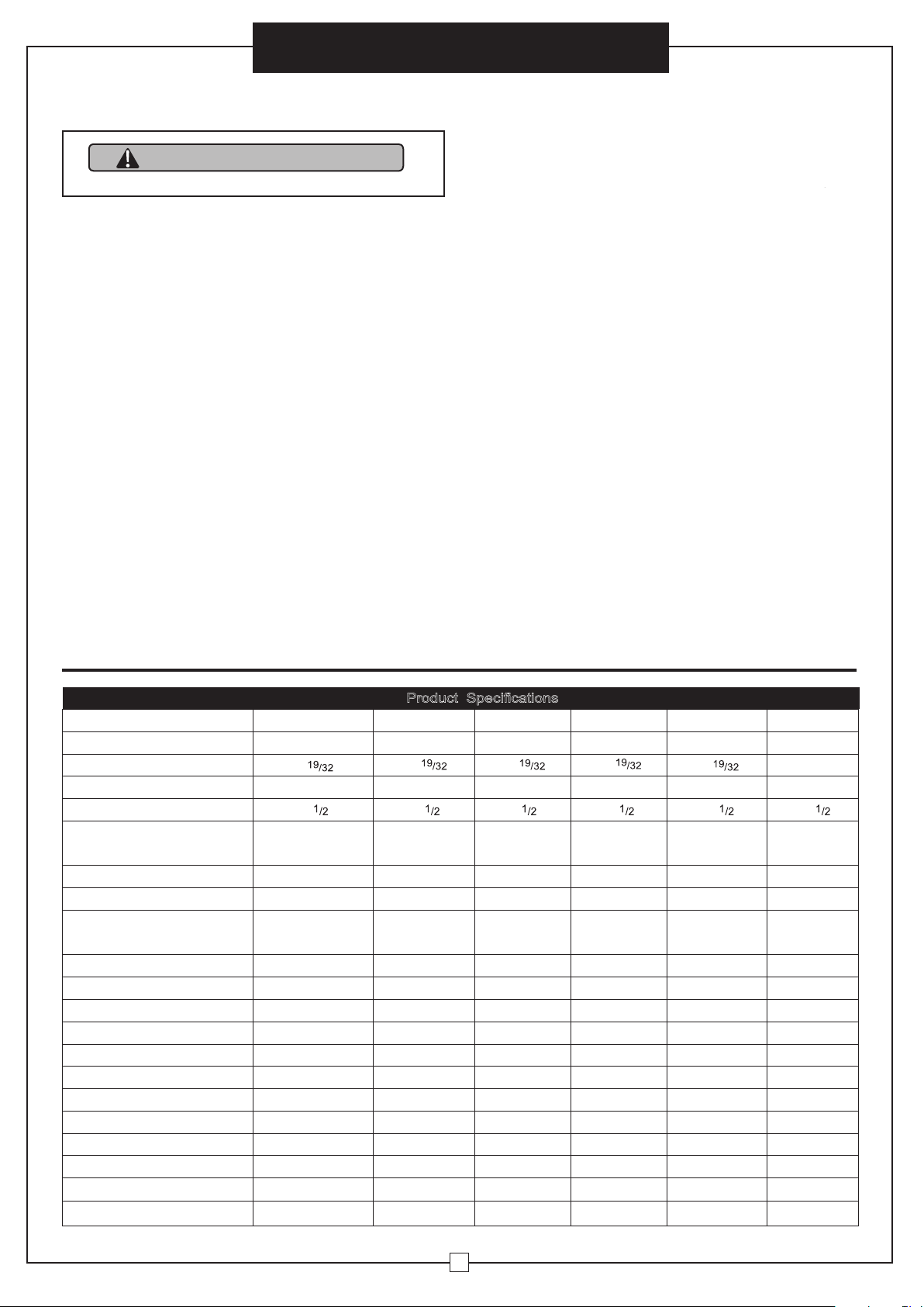
Product Specifications
Model 653558 653559 653560 653561 653562 246067
Length Inches 21
19
/
32
21
19
/
32
21
19
/
32
21
19
/
32
21
19
/
32
22
Width Inches 28 28 28 28 28 28
Height Inches 38
1
/2
38
1
/2
38
1
/2
38
1
/2
38
1
/2
38
1
/2
Wire Size
For Installation
NEMA 6-50P Plug
with 8‘L cable
(comes with the unit)
6/4 SO,
SOOW
4/3 SO,
SOOW
6/4 SO,
SOOW
12/4 SO,
SOOW
6/4 SO,
SOOW
Net Weight Lbs 63 60 60 60 60 83
Color Orange Orange Orange Orange Orange Orange
Construction
Cold Rolled
Steel
Cold Rolled
Steel
Cold Rolled
Steel
Cold Rolled
Steel
Cold Rolled
Steel
Cold Rolled
Steel
Btu High 34,120 51,180 51,180 51,180 51,180 102,389
Cfm High 1584 1584 1584 1584 1584 1966
Temperature Rise F 105 122 122 122 122 208
Vol ta ge 240 208 240 240 480 480
Phase 131333
Amps 41.7 41.7 62.5 36.1 18.1 36
Watts 10,000 15,000 15,000 15,000 15,000 30,000
Kilowatts 10 15 15 15 15 30
Circuit Breaker Amp rating 50A 50A 75A 45A 25A 45A
Safety Tip-Switch Yes Yes Yes Yes No No
Limited Warranty Years 111111
Certification CSA,CSAus CSA,CSAus CSA,CSAus CSA,CSAus CSA,CSAus CSA,CSAus
WARNING
Please read all instructions before using this heater.
Model
Length Inches
Width Inches
Height Inches
Wire Size For Installation
(comes with the unit)
Net Weright Lbs.
Color
Construction
Btu High
Cfm High
Temperature Rise
o
F
Voltage
Phase
Amps
Watts
Kilowatts
Limited Warranty Years
Certification
Wall/Ceiling Model
653558
653673
653671 653672653670
246068
653674
653566
653567 653568 653569
Circuit Breaker Amp rating
Safety Tip-Switch
21
22
28
28
28 28 28 28
38
63 60 60 60 60 83
Orange Orange Orange Orange Orange Orange
NEMA 6-50P Plug
with 8’L cable
6/4 SO,
SOOW
4/3 SO,
SOOW
6/4 SO,
SOOW
6/4 SO,
SOOW
12/4 SO,
SOOW
Cold Rolled
Steel
Cold Rolled
Steel
Cold Rolled
Steel
Cold Rolled
Steel
Cold Rolled
Steel
Cold Rolled
Steel
46 61 46 46 46 65
34,120 51,180 102,389
1584
51,180 51,180 51,180
1584 1584 1584 1584 1966
240 208 480 480240 240
131333
41.7 62.541.7 36.1 18.1 36
10,000 30,00015,000 15,000 15,000 15,000
10 15 3015 1515
50A 25A75A 45A50A 45A
YES YES YES YES YES YES
111111
CSA,CSAUS CSA,CSAUS CSA,CSAUS CSA,CSAUS CSA,CSAUS CSA,CSAUS
Product Specifications
21 21
21
21
38 38 38 38 38
6
(1.8m) 4 feet (1.2m)
Salamander
Heater
Page 3
User’s Manual
3
Electric Blower Heater
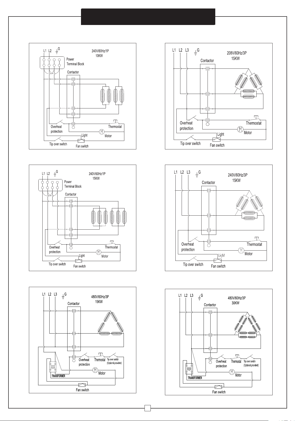
Wiring Diagrams
653558
240V/60Hz/1P
10KW
653560
240V/60Hz/1P
15KW
653562
480V/60Hz/3P
15KW
246067
480V/60Hz/3P
30KW
653561
240V/60Hz/3P
15KW
653559
208V/60Hz/3P
15KW
Overheat
Protection
Tip over switch
Tip over switch
Tip over switch
Tip over switch
Overheat
Protection
Overheat
Protection
Overheat
Protection
Overheat
Protection
Overheat
Protection
Thermostat
Thermostat
Thermostat Thermostat
Thermostat
Thermostat
Motor
Motor
Motor Motor
Motor
Motor
Light
Light Light
Light
Fan Switch
Fan Switch
Fan Switch Fan Switch
Fan Switch
Fan Switch
L1
L1
L1 L1L2 L2L3 L3
L1 L2
G
G
G
G
G
G
L2
L2 L2 L3L1
L3
653560 653567
653561
653562
246067
653559
653558
Assembly Instructions
653673 653566
653671 653568
653672 653569
653674 246068
653670 653567
Salamander
Heater
Page 4
Assembly Instructions
4
Electric Blower Heater
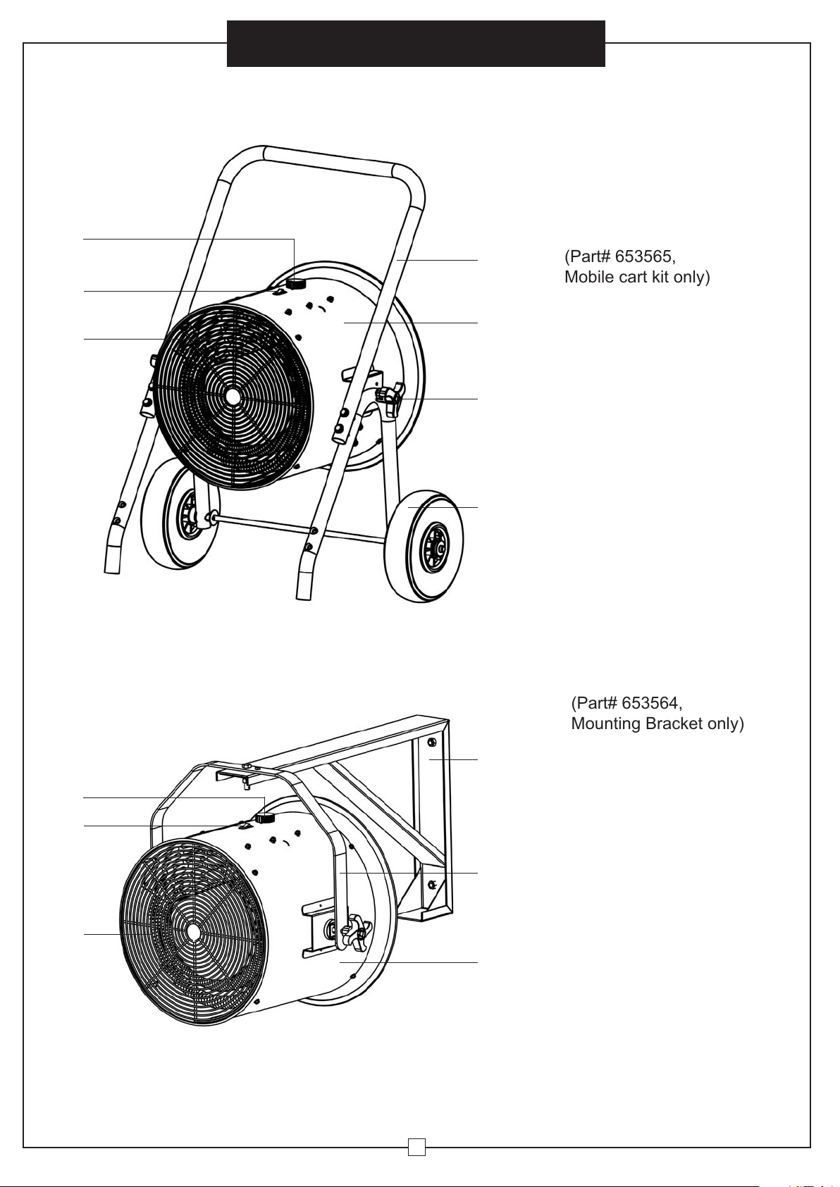
A. Handle
B. Heater Housing
C. Tilt Adjustable Knob
D. Wheel
E. Front Exhaust Grill
F. On/Off Switch
G. Temperature Setting Knob
A. Wall Mount Bracket
B. Hanger
C. Heater Housing
D. Front Exhaust Grill
E. On/Off Switch
F. Temperature Setting Knob
PARTS LIST
Cart-Stand
Wall Mount
A
A
B
C
B
C
E
D
F
E
G
F
D
Salamander
Heater
Wall/Ceiling Mounting Bracket
(Part# 653564,
Mounting Bracket only)
(Part# 653565,
Mobile cart kit only)
Page 5
Tighten M12 nuts (6) to wheels.
WARNING
All wiring must be installed by a certified
electrician in accordance with electrical
safety standards.
CAUTION
Keep electrical cords, drapery,
furnishings and other combustibles
at least 3 feet (0.9 m) from heater,
to prevent risk of fire.
WARNING
To reduce the risk of fire, do not store or
use gasoline or other flammable vapors
and liquids near the heater.
5
Electric Blower Heater
All wiring procedures and connections must be in
accordance with national and local codes.
Prior to installation:
Disconnect the main supply connection.
The heater must be connected to individual rated branch circuit
breaker only. (See spec sheet).
Use proper conductor size for power supply. (See spec sheet).
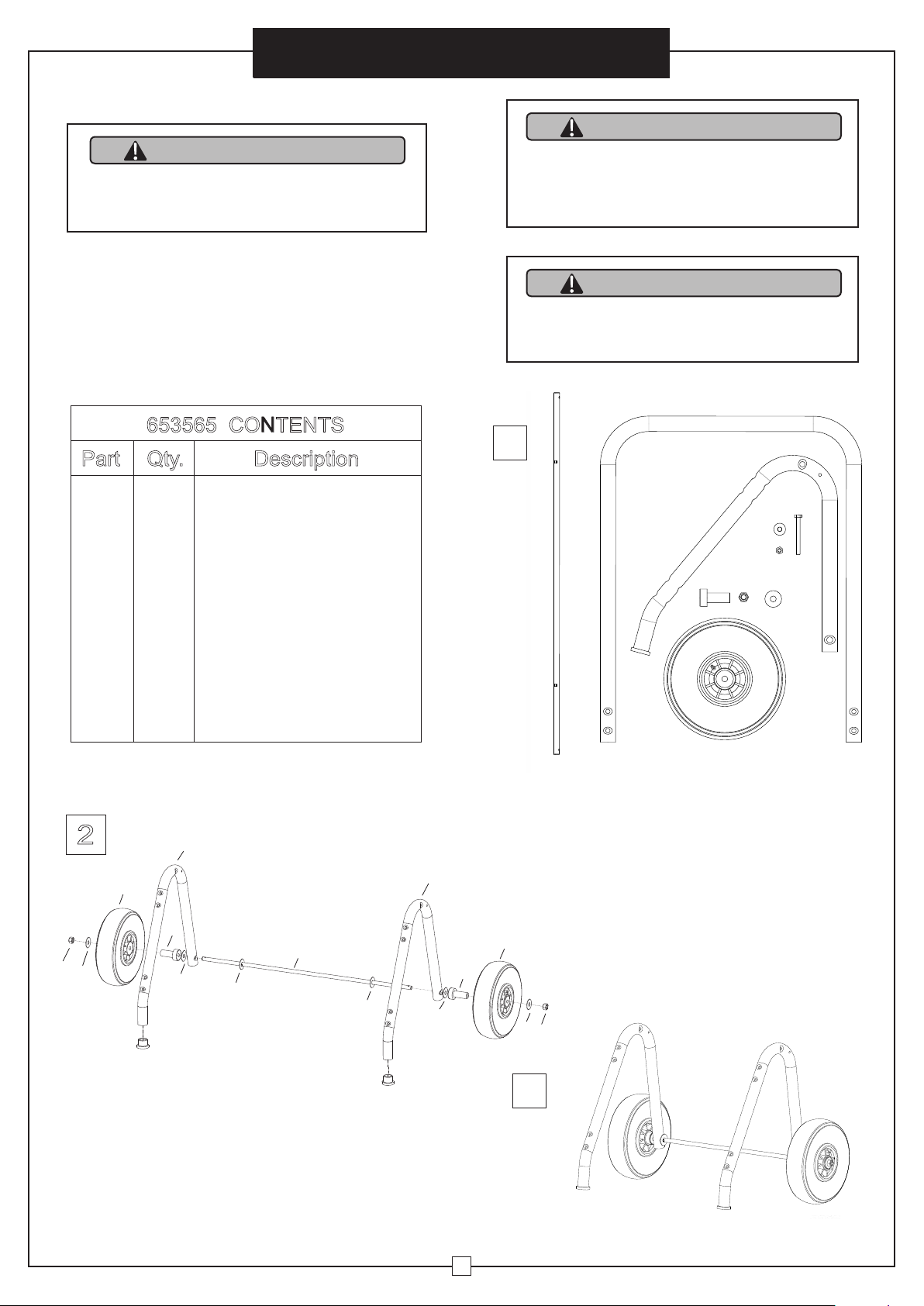
INSTALLATION INSTRUCTIONS
Open package and remove heater and
assembly components.
User’s Manual
1
2
CONTENTS
Part Qty. Description
1 1 Axle
2 1 Handle
3 2 Foot Stand
4 2 Wheel
5 2 Bushing
6 2 M12 Nut
7 4 12mm ID Washer
84M8 Nut
9 8 8mm ID Washer
10 4 M8 x 80 Screw
11 2 M6 x 55 Screw
12 2 6mm ID Washer
13 2 M6 x 20 Nut
14 2 Knob
15 2 10mm ID Washer
16 2 50 x 10mm Rubber Pad
Use axle (1), bushing (5) and 12mm ID
washer (7) to assemble foot stand (2)
and wheels (4).
1
3
56 7
8
9
10
11
14 15 16
12 13
4
2
1
2
3
5
6
7
8
9
10
4
653565 CONTENTS
Part Qty. Description
1
2
3
4
5
6
7
8
9
10
1
1
2
2
2
6
4
4
8
Axle
Handle
Foot Stand
Wheel
Bushing
M12 Nut
M8 Nut
12mm ID Washer
8mm ID Waher
M8 x 80 Screw
2
2.Use axle (1), bushing (5) and 12mm ID washer (7)
to assemble foot stand (3) and wheels (4).
3. Tighten M12 nuts (6) to wheels.
3
3
4
5
6
7
7
7
7
7
7
1
5
4
6
CART INSTALLATION INSTRUCTION
3
1.Open package and remove heater and
assembly components.
2
Assembly Instructions
Salamander
Heater
Page 6
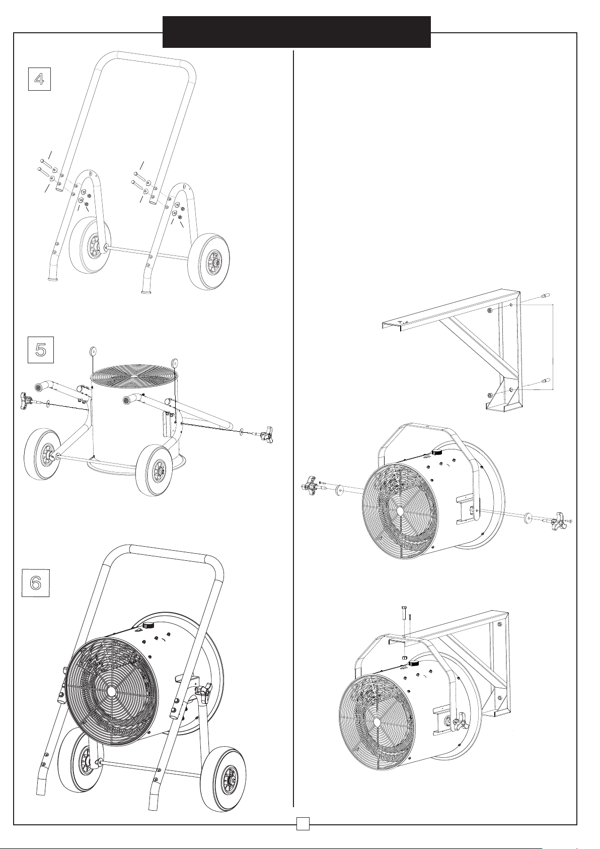
5.Use 50 x 10 rubber pad, 10mm ID washer and konb to
aach heater to foot stand. Tighten knobs.
4.Use M8 x 80 screw (10), 8mm ID washer (9), and M8
nut (8) to aach handle to foot stand. Tighten.
10
9
8
10
9
8
9
9
6
Salamander
Heater
Assembly Instructions
6.Connect the electrical power supply cable to the wiring
compartment. (See wiring instructions).
Attach connectors to the appropriate conductor and ground
wiring. After completing the connections, arrange pigtail
unit leads and power supply wires in wiring compartment.
Wall Mount Installation Instructions:
1. Keep unit at least 6 feet (1.8 m) away from floor. Minimum
distance must be maintained.
2. Do not install closer than 4 feet (or 1.2 m) to any adjacent
vertical surfaces or walls.
3. Keep at least 4.5 inches (11.5 cm) from back wall (with or
without wall hanging mounting bracket).
4. Mark drill-hole positions in wall or ceiling for mounting
bracket.
5. Drill holes for required diameter fit (anchor provided) to
ensure correct position for mounting bracket.
6. Insert anchors.
13"
7. Confirm mounting bracket is securely
attached to wall or ceiling with screws.
8. Attach bracket to heater housing with knobs and
rubber pads. Insert lock pin.
9. Mount heater assembly onto mounting bracket and
align holes. Insert hex bolt and tighten with nut. Install lock
pin.
4
5
6
Page 7
7
Electric Blower
Heater
10. Connect the electrical power supply cable in flexible
conduit to wiring compartment.
11. Attach with connectors suitable for conductor size
and ground wiring. After completing the connections,
arrange pigtail unit leads and power supply wires in
wiring compartment.
OPERATING INSTRUCTIONS
HAZARD OF ELECTRIC SHOCK,
EXPLOSION OR ARC FLASH:
• Apply appropriate personal protective equipment
(PPE) and follow safe electrical work practices.
See NFPA 70
• Circuit breaker must be installed and serviced only
by qualified electrical personnel.
• Always use a properly rated voltage device to
confirm power is off.
• Confirm there are no materials near front or
rear grills.
• Switch on the circuit breaker and On/Off rocker switch
to turn on heater. Turn thermostat to furthest clockwise
position. Fan will begin heating the room.
• Select a thermostat setting. Ambient temperature is
regulated by adjusting the thermostat to a desired
position. Allow unit to operate and warm the room.
When desired temperature is reached, turn control knob
counterclockwise until heater turns off. The heater will
start automatically when the room temperature drops
below this set point and will turn off when set point is
reached. The fan will remain on.
• Adjust thermostat with each use.
• To turn off heater, position the On/Off rocker switch
and circuit breaker to Off.
SAFETY TIP-OVER SWITCH
All Models are designed to automatically shut off when
heater is tipped sideways. Place unit on level surface to
prevent tipping.
MAINTENANCE AND CLEANING
All servicing or maintenance should be performed by
qualified service personnel.
Prior to maintenance be sure to:
1. Disconnect power supply at source.
2. Wait 60 minutes to ensure heating element is cool.
Routine Maintenance:
1. Do not spray or use cleaning liquids or other chemicals
on unit.
2. Interior dust can often be removed with a vacuum
cleaner and crevice tool attachment.
3. To clean enclosure, use a clean, soft and lightly damp
cloth to gently wipe off dirt from surface. Be sure not
to wet heating element or switches. Allow unit to dry
completely before restarting.
WARNING
!
This unit must only be used with the provided floor
stand or optional ceiling bracket. Heater must be
installed with the power switch at the top of the unit.
CAUTION
!
Do not allow water to run into the interior of the
heater as this could cause a fire, an electric shock
hazard and damage the unit.
Assembly Instructions
MODELS 653558, 653673, 653670, 653671,653672,
653566, 653567, 653568 & 653569
These heaters have thermal cut-off protection. If the
thermal cut-off protection trips:
Turn off the power. Turn Off the circuit breaker.
The unit should reset automatically after 10 minutes.
OVERHEAT & RESET
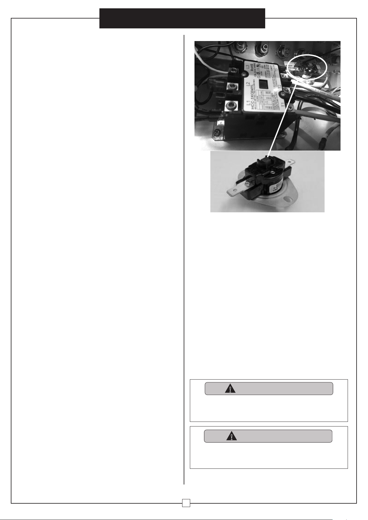
MODELS 653674 & 246068
This heater has Manual reset thermal cut-off protection. If
the thermal cut-off protection trips:
Turn off the power. Turn Off the circuit breaker. Let the
unit cool down for 15 minutes.
Then follow the Manual reset procedure to reset the
thermal cut-off.
1.Open the cover of connection compartment.
2.Identify the Manual reset thermal cut-off with square red
button as follow.
3.Press the red button to reset the thermal cut-off.
If the thermal cut-off protection trips again, consult a
certified electrician to determine the reason of overheating.
Salamander
Heater
Page 8
8
Electric Blower Heater
TROUBLESHOOTING
ProblemProbable Cause Solution
Unit is not
heating.
Overheat protection has temporarily
deactivated the heater.
Tur n the heater OFF; Switch off the circuit
breaker. Wait 10 minutes before restarting unit.
Br
eaker/Fuse has been tripped. Check electrical box to confirm the breaker
has not been blown. This may occur if the
receptacle is shared between other high
consumpti
on appliances.
The heater is
producing
a burning smell.
Verify that there are no combustible
materials within 0.9 meters (3 feet)
surrounding the heater.
Remove any combustible items near unit.
T
here is oil residue on the heating coil
from the manufacturing process. It will
evaporate quic kly and should not occur
again.
Ensure heater location is well ventilated.
Ensure a minimum cleara
nce of 4.5 inches
(11.5 cm) from heater to adjacent walls.
Reposition heater to increase distance from
adjacent walls.
PLEASE DO NOT ATTEMPT TO OPEN OR REPAI R THE HEAT ER YOURSELF.
DOING SO COULD CAUSE DAMAGE OR PERSONAL INJURY.
This is a cart stand or wall-mounted heater. It has thermal
cut-off protection. If the thermal cut-off protection trips:
Tur n off the power. Tur n off the circuit breaker.
The unit
should reset automatically after 10 minutes. If the thermal
cut-off protection trips again, consult a certified electrician
to determine the reason for overheating.
If your heater fails to operate, please follow these procedures:
User’s Manual
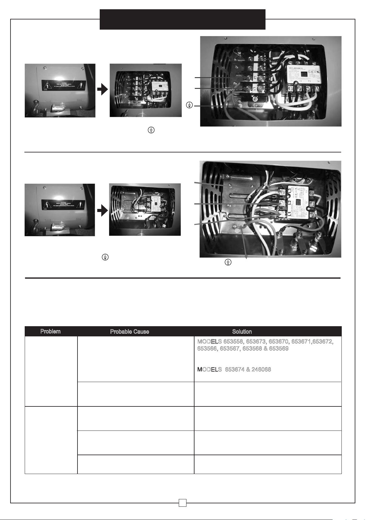
WIRING INSTRUCTIONS
For Model 653560
Models 653561 653562 246067
FOR 3 PHASE MODELS:
1. Open the compartment.
1. Open the wiring cover.
3. Close compartment.
Note: Use wire terminal crimp when connecting
to terminals.
3. Close compartment.
Ground wire
2. Connect the live wires to L1 and L2 of the
terminal block. Connect ground wire to .
2. Connect the red live wire to L1, black live wire
to L2 and white live wire to L3 of the connector.
Connect ground wire to .
L1: Red live wire L2: Black live wire L3: White live wire
L1: White live wire L2: Black live wire
L1
L2
L1
L2
L3
653559 653561 653562 246067
L3
L1
For Models 653558, 653670 & 653567
Models 653673, 653671, 653672, 653674, 653566, 653568,
653569 & 246068
Unit is not
heating.
Overheat protection has temporarily
deactivated the heater.
Breaker/Fuse has been tripped.
MODELS 653558, 653673, 653670, 653671,653672,
653566, 653567, 653568 & 653569
Turn the heater OFF; Switch off the circuit
breaker.
Wait 10 minutes before restarting unit.
MODELS 653674 & 246068
Please refer to Page 7 Overheat & Reset.
Check electrical box to confirm the breaker has not
been blown. This may occur if the receptacle is shared
between other high consumption appliances.
The heater is
producing
a burning smell.
Remove any combustible items near unit.
Ensure heater location is well ventilated.
Reposition heater to increase distance from
adjacent walls.
Verify that there are no combustible materials
within 0.9 meters (3 feet) surrounding the
heater.
There is oil residue on the heating coil from
the manufacturing process. It will evaporate
quickly and should not occur again.
Ensure a minimum clearance of 4.5 inches
(11.5 cm) from heater to adjacent walls.
Problem
Probable Cause Solution
Salamander
Heater
Page 9

De Aire ECalentador
Modelos: 653561 653560 653
653558 653562 246067
g
globalindustrial.ca
Instrucciones de EnsamblaAssembly Instructions
Customer Service
US: 1-800-645-2986
Servicio de atención al Clien
México: 01.800.681.6940
tricoléc
DE CFDistribucion Industrial Globales S DE RL
Dir
Service à la clientèle
Canada: 888-645-2986
CIONES
050117
1
LEA Y CONSE
ESTAS INSTRUC
Wall Mount Modelos: 653566 653567 653568
653569 246068
Modelos: 653558 653673 653670
653671 653672 653674
Wall/Ceiling Modelos: 653566 653567 653568
653569 246068
Calentador De Salamandra
Page 10

Instrucciones de Ensamblaje
2
Calentador De Aire Eléctrico
NOTA: este producto debe ser instalado por un electricista
certificado de conformidad con las normativas locales.
6. Los rastros de humo u olor cuando se inicia la unidad indican
que pequeñas cantidades de aceite se filtraron de la resistencia
para calentamiento durante la fabricación. El aceite se evaporará
rápidamente y no debe volver a ocurrir. Asegúrese de ubicar el
aparato en un área bien ventilada durante la instalación. Es normal
que la unidad emita sonidos cuando se enciende por primera vez.
7. Por favor, siga estas precauciones básicas cuando utilice
aparatos eléctricos para reducir el riesgo de incendio, descarga
eléctrica y daños personales o materiales:
1. Lea todas las instrucciones antes de usar el calentador.
2. La unidad se calentará cuando esté en uso. Evite que su piel entre en
contacto con superficies calientes para prevenir lesiones. Mantenga
materiales combustibles, como muebles, ropa de cama, prendas de
vestir, etc., por lo menos a 90 cm de distancia del calentador.
3. Precaución y supervisión Extreme es necesario cuando se usa
cualquier calentador cerca de niños o mascotas y cuando el
calentador se deje funcionando sin vigilancia.
4. Apague siempre el calentador cuando no esté en uso.
5. No utilice el calentador si la unidad no está funcionando correctamente,
se cayó o está dañada de alguna manera. Desconecte la corriente en
el panel de servicio y consulte a un electricista certificado para que
revise el calentador antes de volver a usarlo.
6. No utilice el calentador en exteriores
7. Para desconectar el calentador, corte la corriente en el panel principal
de desconexión.
8.
Para instalar el calentador en el techo o la pared, no lo sitúe a menos de
2,4 m de altura desde el suelo y a menos de 30 cm para las superficies
adyacentes verticales o paredes. Mantenga la unidad al menos a 11,5
cm de la pared posterior (con o sin soporte de montaje de pared).
9. Cuando utilice una carretilla, asegúrese de que este sobre un terreno
plano. Mantenga por lo menos a 30 cm de cualquier superficie
adyacente vertical o paredes, y a 30 cm de la pared trasera.
10. No inserte, ni permita que entren, objetos extraños en las aberturas
de ventilación o escape, ya que podría provocar un incendio o
descarga eléctrica, o dañar el calentador.
11. Para evitar un posible incendio, no bloquee de ninguna manera las
entradas o salidas de aire.
12. Las unidades contienen equipos calientes y de formación de arcos
eléctricos internos. Para reducir el riesgo de incendio, no utilice el
calentador en zonas donde se use o almacene gasolina, pintura, o
vapores y líquidos inflamables.
13. Utilice el calentador sólo como se describe en este manual.
Cualquier otro uso no recomendado por el fabricante puede
provocar incendios, descargas eléctricas o lesiones.
14. Este calentador no está diseñado para su uso en baños, áreas de
lavandería y recintos similares cerrados. Nunca ubique el calentador
cerca del agua.
Para el modelo 653558 sólo
15. Enchufe el calentador directamente en un toma/receptáculo de pared.
Evite emplear extensiones o regletas debido al sobrecalentamiento
y el riesgo de incendio.
INSTRUCCIONES DE IMPORTANCIA
Especificaciones del Producto
Modelo
653558 653559 653560 653561 653562 246067
Largo Pulgadas
21
19
/
32
21
19
/
32
21
19
/
32
21
19
/
32
21
19
/
32
22
Ancho Pulgadas
28 28 28 28 28 28
Alto Pulgadas
38
1
/2
38
1
/2
38
1
/2
38
1
/2
38
1
/2
38
1
/2
Tamaño
Cable para
NEMA 6-50P Enchufe
con Cable L
(viene con la unidad)
6/4 SO, SOOW 4/3 SO, SOOW 6/4 SO, SOOW 12/4 SO, SOOW 6/4 SO, SOOW
Peso Neto Lbs.
63 60 60 60 60 83
Color
Naranja
Orange Orange Orange Orange Orange
Estructura
Acero Laminado
en Frío
Acero Laminado
en Frío
Acero Laminado
en Frío
Acero Laminado
en Frío
Acero Laminado
en Frío
Acero Laminado
en Frío
Altura Btu
34,120 51,180 51,180 51,180 51,180 102,389
Altura Cfm
1584 1584 1584 1584 1584 1966
Alza Temperatura °F
105 122 122 122 122 208
Voltaje
240 208 240 240 480 480
Fase
131333
Amps
41.7 41.7 62.5 36.1 18.1 36
Vatios
10,000 15,000 15,000 15,000 15,000 30,000
Kilovatios
10 15 15 15 15 30
Interruptor de circuito
nominal de amperios
50A 50A 75A 45A 25A 45A
Sécurité Tip-Switch
Oui Oui Oui Oui Non Non
Años Garantía
Limitada
111111
Certificación
CSA,CSAus CSA,CSAus CSA,CSAus CSA,CSAus CSA,CSAus CSA,CSAus
ADVERTENCIA
Por favor, lea completamente las instrucciones
antes de usar el calentador.
1,8 1,2
Modelo
Largo Pulgadas
Ancho Pulgadas
Alto Pulgadas
Tamaño Cable para
(Viene con la unidad)
Peso Neto Lbs.
Color
Estructura
Altura Btu
Altura Cfm
Alza Temperatura
o
F
Voltaje
Fase
Amps
Vatios
Kilovatios
Años Garantía Limitada
Certificación
Wall/Ceiling Modelo
653558
653673
653671 653672653670
246068
653674
653566
653567 653568 653569
Interruptor de circuito
nominal de amperios
21
22
28
28
28 28 28 28
38
63 60 60 60 60 83
Orange Orange Orange Orange Orange Orange
NEMA 6-50P Enchufe
con Cable L
6/4 SO,
SOOW
4/3 SO,
SOOW
6/4 SO,
SOOW
6/4 SO,
SOOW
12/4 SO,
SOOW
Acero Laminado
en Frío
46 61 46 46 46 65
34,120 51,180 102,389
1584
51,180 51,180 51,180
1584 1584 1584 1584 1966
240 208 480 480240 240
131333
41.7 62.541.7 36.1 18.1 36
10,000 30,00015,000 15,000 15,000 15,000
10 15 3015 1515
50A 25A75A 45A50A 45A
Oui Oui Oui Oui Oui Oui
111111
CSA,CSAUS CSA,CSAUS CSA,CSAUS CSA,CSAUS CSA,CSAUS CSA,CSAUS
Especificaciones del Producto
21 21
21
21
38 38 38 38 38
Sécurité Tip-Switch
Acero Laminado
en Frío
Acero Laminado
en Frío
Acero Laminado
en Frío
Acero Laminado
en Frío
Acero Laminado
en Frío
Calentador De Salamandra
Modelo
Wall Mount Modelo
Largo Pulgadas
Ancho Pulgadas
Alto Pulgadas
Tamaño
Cable para
Peso Neto Lbs.
Color
Estructura
Altura Btu
Altura Cfm
Alza Temperatura
Voltaje
Fase
Amps
Vatios
Kilovatios
Interruptor de circuito
nominal de amperios
Sécurité Tip-Switch
Años Garantía Limitada
Certificación
Especificaciones del Producto
653558
NEMA 6-50P Enchufe
(Viene con la unidad)
o
F
Acero Laminado
21
28
38
con Cable L
63 60 60 60 60 83
Orange Orange Orange Orange Orange Orange
en Frío
34,120 51,180 102,389
1584
46 61 46 46 46 65
240 208 480 480240 240
41.7 62.541.7 36.1 18.1 36
10,000 30,00015,000 15,000 15,000 15,000
10 15 3015 1515
50A 25A75A 45A50A 45A
Oui Oui Oui Oui Oui Oui
CSA,CSAUS CSA,CSAUS CSA,CSAUS CSA,CSAUS CSA,CSAUS CSA,CSAUS
131333
111111
653559
653566
21 21
28
6/4 SO,
SOOW
Acero Laminado
en Frío
38 38 38 38 38
1584 1584 1584 1584 1966
653567 653568 653569
28 28 28 28
4/3 SO,
SOOW
Acero Laminado
en Frío
51,180 51,180 51,180
653561 653562653560
21
6/4 SO,
SOOW
Acero Laminado
en Frío
21
12/4 SO,
SOOW
Acero Laminado
en Frío
Acero Laminado
en Frío
246067
246068
22
6/4 SO,
SOOW
Page 11

Instrucciones de Ensamblaje
3
Calentador De Aire Eléctrico
Diagramas de Cableado
653558
240V/60Hz/1P
10KW
653560
240V/60Hz/1P
15KW
653562
480V/60Hz/3P
15KW
246067
480V/60Hz/3P
30KW
653561
240V/60Hz/3P
15KW
653559
208V/60Hz/3P
15KW
Astuce commutateur
Astuce commutateur Astuce commutateur
Astuce commutateur
Protección
Sobrecalentamiento
Protección
Sobrecalentamiento
Protección
Sobrecalentamiento
Protección
Sobrecalentamiento
Protección
Sobrecalentamiento
Termostato
Termostato
Termostato Termostato
Termostato
Termostato
Motor
Motor
Motor Motor
Motor
Motor
Luz
Luz Luz
Luz
Interruptor Ventilador
Interruptor Ventilador
Interruptor Ventilador Interruptor Ventilador
Interruptor Ventilador
Interruptor Ventilador
L1
L1
L1 L1L2 L2L3 L3
L1 L2
G
G
G
G
G
G
L2
L2 L2 L3L1
L3
Protección
Sobrecalentamiento
Instrucciones de Ensamblaje
653673 653566
653671 653568
653672 653569
653674 246068
653670 653567
Calentador De Salamandra
Protección
Sobrecalentamiento
Astuce commutateur
El poder del
bloque de terminales
Luz
Interruptor Ventilador
653560
El poder del
bloque de terminales
653558
653567
Termostato
Protección
Sobrecalentamiento
Astuce commutateur
653559
Luz
Interruptor Ventilador
653561
653566
Termostato
653568
Protección
Sobrecalentamiento
Luz
Astuce commutateur
Interruptor Ventilador
653562 653569
Te rm os t at o
Protección
Sobrecalentamiento
Astuce commutateur
Transformador
Sobrecalentamiento
Interruptor Ventilador
ermostatoProtección
T
Astuce
commutateur
Transformador
Luz
Interruptor Ventilador
246067 246068
Protección
Sobrecalentamiento
Interruptor Ventilador
Termostato
Termostato
Astuce
commutateur
Page 12

Instrucciones de Ensamblaje
4
Calentador De Aire Eléctrico
A. Manilla
B. Carcasa Calentador
C. Perilla Ajuste Inclinación
D. Rueda
E. Rejilla Escape Frontal
F. Conmutador On/Off
G. Perilla Configuración
Temperatura
A. Soporte mural
B. Colgador
C. Carcasa Calentador
D. Rejilla Escape Frontal
E. Conmutador On/Off
F. Perilla Configuración
Temperatura
LISTA PARTES
Pedestal Carro
Instalación Mural
A
A
B
C
B
C
E
D
F
E
G
F
D
Calentador De Salamandra
(Part# 653565,
Solo kit de carro móvil)
(Part# 653564,
Solo soporte de montaje)
Soporte de pared para techo
Page 13

5
Calentador De Aire Eléctrico
Manual del usuario
INSTRUCCION DE INSTALACIÓN DE
CARRO
ADVERTENCIA
!
Todo el cableado debe ser instalado por un
técnico electricista certificado, en conformidad
con los estándares de seguridad eléctrica.
PRECAUCIÓN
!
Mantenga los cables eléctricos, cortinas,
muebles y otros combustibles
por lo menos 3 pies (0,9 m) de calentador,
para prevenir el riesgo de incendio.
ADVERTENCIA
!
Para reducir el riesgo de incendio, no
almacene ni use gasolina u otros vapores y
líquidos inflamables cerca del calentador.
Todos los procedimientos de cableado y conexiones
deben ser acordes con la normativa local y nacional.
Antes de la instalación:
Desconectar la conexión principal de suministro.
El calentador debe estar conectado al interruptor automático derivado puntuación individual solamente. (Ver
hoja de especificaciones).
Utilice el tamaño del conductor adecuado para la fuente
de alimentación. (Ver hoja de especificaciones).
CONTENIDO
Parte Cant. Descripción
1
2
3
4
5
6
7
8
9
10
1
1
2
2
2
6
4
4
8
Eje
Palanca
Soporte de pie
Rueda
Buje
Tuerca M12
Tuerca M8
Arandela de12mm
Arandela de 8mm
Tornillo M8 x 80
2
653565
1
2
3
5
6
7
8
9
10
4
1
1. Abra el paquete, extraiga el calentador y
ensamble los componentes.
3
3
4
5
6
7
7
7
7
7
7
1
5
4
6
2
2. Emplee el eje (1), el buje (5) y la
arandela de 12mm (7) para armar el
soporte de pie (3) y las ruedas (4).
3. Ajuste las tuercas
M12 (6) a las ruedas.
3
Calentador De Salamandra
Page 14

5.Ulice la almohadilla de goma 50 x 10, la arandela de
10mm y la perilla para fijar el calentador al soporte de
pie. Apriete las perillas.
4.Use el tornillo M8 x 80 screw (10), la arandela de 8mm (9)
y la tuerca M8 (8) para fijar la manija al soporte de pie.
Apriete.
10
9
8
10
9
8
9
9
6
Calentador De Aire Eléctrico
Manual del usuario
6.Conecte el cable de suministro de energía eléctrica al
compartimiento de cableado (ver instrucciones de
cableado).Fije los conectores al conductor y cableado de
tierra apropiados. Después de completar las conexiones,
organice los conectores y los cables de alimentación en el
compartimiento de cableado.
Instrucciones de instalación para el montaje en
pared:
1. Mantenga la unidad a por lo menos 1,8 m de distancia del
suelo. Debe mantener la distancia mínima.
2. No instale el calentador a menos de 30 cm de las
superficies adyacentes verticales o paredes.
3. Mantenga la unidad al menos a 11,5 cm de la pared
posterior (con o sin soporte de montaje).
4. Marque los agujeros a perforar en la pared o en el techo
para el soporte de montaje.
5. Perfore los agujeros del diámetro requerido (anclajes
proporcionados) para asegurar la posición correcta para el
soporte de montaje.
6. Inserte los anclajes.
13"
7. Asegúrese de que el soporte de
montaje está fijado correctamente con
los tornillos a la pared o al techo.
8. Instale el conjunto del calentador encima del soporte de
montaje y alinee los orificios. Inserte el perno hexagonal y
apriete usando tuerca. Ponga el pasador de bloqueo.
9. Inserte el tornillo de cabeza hexagonal a través del gancho
y soporte de montaje, y apriete la tuerca.
4
5
6
Calentador De Salamandra
Page 15

7
Calentador De Aire Eléctrico
Manual del usuario
10. Conecte el cable del suministro de energía eléctrica en
el conducto flexible al compartimiento del cableado.
11. Fije con los conectores adecuados al tamaño del
conductor y al cableado de tierra. Después de c
ompletar las conexiones, organice los conectores y los
cables del suministro de energía en el compartimiento
de cableado.
INSTRUCCIONES DE USO
PELIGRO DE DESCARGA ELÉCTRICA,
EXPLOSIÓN O ARCO ELÉCTRICO:
• Utilice un equipo de protección personal (EPP)
apropiado y siga las prácticas de seguridad eléctrica.
Consulte la norma NFPA 70.
• Solo el personal calificado puede instalar y darle
servicio de mantenimiento al disyuntor. Siempre
utilice un multímetro de rango adecuado para
confirmar la desenergización
• Confirme que no haya materiales cerca de las rejillas
delanteras o traseras.
• Encienda el disyuntor y apriete el interruptor eléctrico
de encendido/apagado para encender el calentador.
Gire el termostato lo más que pueda en el sentido de
las agujas del reloj. El ventilador comenzará a calentar
la habitación.
• Seleccione una configuración para el termostato. La
temperatura ambiente se regula al ajustar el termostato a
una posición deseada. Deje que la unidad opere y caliente
la habitación. Cuando se alcance la temperatura deseada,
gire la perilla de control en contra de las agujas del reloj
hasta que se apague el calentador. El calentador se
encenderá automáticamente cuando la temperatura
ambiente descienda por debajo del punto ajustado, y se
apagará cuando se alcance ese punto. El ventilador
permanecerá encendido.
• Ajuste el termostato con cada uso.
• Para apagar el calentador, coloque tanto el interruptor de
encendido/apagado como el disyuntor en apagado.
INTERRUPTOR DE SEGURIDAD
Todos los modelos están diseñados para apagarse
automáticamente cuando el calentador se incline hacia los
lados. Coloque la unidad en una superficie plana para
evitar que esto suceda.
MANTENIMIENTO Y LIMPIEZA
Solo el personal de servicio calificado debe realizar el
servicio o mantenimiento.
Antes del mantenimiento, asegúrese de:
1. Desconectar el suministro eléctrico en la fuente.
2. Esperar 60 minutos para garantizar que el elemento
calefactor esté frío.
Mantenimiento de rutina:
1. No rocíe o utilice líquidos de limpieza u otros productos
químicos en la unidad.
2. A menudo, el polvo interior se puede quitar con una
aspiradora y el accesorio para hendiduras.
3. Para limpiar el compartimiento, utilice un paño limpio,
suave y ligeramente húmedo para quitar cualquier
suciedad de la superficie. Asegúrese de no mojar el
elemento calefactor ni los interruptores. Permita que la
unidad se seque completamente antes de volver a
encenderla.
ADVERTENCIA
!
Esta unidad sólo debe utilizarse con el soporte de
suelo suministrado o el soporte de techo opcional.
El calentador debe instalarse con el interruptor de
encendido en la parte superior de la unidad.
PRECAUCIÓN
!
No permita que el agua llegue al interior del
calentador, ya que podría causar un incendio o una
descarga eléctrica y dañar la unidad.
MODELOS 653558, 653673, 653670, 653671,653672,
653566, 653567, 653568 & 653569
Estos calentadores tienen protección térmica de corte.
Si el viajes de protección de corte térmico:
Apague la alimentación. Apague el interruptor de
circuito.
La unidad debe reiniciarse automáticamente después de
10 minutos.
Recalentamiento y reposición
MODELOS 653674 & 246068
Este calentador tiene protección de corte térmico de
restablecimiento manual. Si se dispara la protección
térmica de corte:
Apague la alimentación. Apague el interruptor de circuito. Deje que la unidad se enfríe durante 15 minutos.
A continuación, siga el procedimiento de restablecimiento
manual para restablecer el
corte térmico.
1.Abra la tapa del compartimento de conexión.
3.Pulse el botón rojo para restablecer el corte térmico.
Si la protección térmica de corte se dispara nuevamente,
consulte a electricista certificado para determinar el motivo
del sobrecalentamiento.
2.Identifique el corte térmico de restablecimiento manual
con el botón cuadrado rojo como sigue.
Calentador De Salamandra
Page 16

8
Instrucciones de Ensamblaje
SOLUCIÓN DE PROBLEMAS
Problema Causa probable Solución
La unidad
no está
calentando.
La protección contra el sobrecalentamiento
ha desactivado temporalmente el calentador.
Apague el calentador. Apague el disyuntor.
Espere 10 minutos antes de reiniciar la unidad.
El disyuntor/fusible se ha disparado.Revise la caja eléctrica para confirmar que el
disyuntor no se haya quemado. Esto puede
ocurrir si comparte el to
ma corriente con otros
aparatos de alto consumo.
El calentador
produce
un olor a
quemado.
Compruebe que no haya materiales
inflamables dentro de 90 cm alrededor
del calentador.
Quite los elementos inflamables que estén
cerca de la unidad.
Hay residuos de aceite en la bobina de
calentamiento que quedaron del proceso
de fabricación. El aceite se evaporará
rápidamente y no debería volver a ocurrir .
Asegúrese de que la ubicación del calentador
esté bien ventilada.
Garantice un espacio mínimo de 11,5 cm desde
el cal
entador hasta las paredes adyacentes.
Reubique el calentador para aumentar la
distancia desde las paredes adyacentes.
POR FAVOR, NO INTENTE ABRIR O REPARAR EL CALENTADOR USTED MISMO.
DE LO CONTRARIO, PODRÍA CAUSAR DAÑOS O LESIONES PERSONALES.
La unidad e s un calentador de pie o de pared con una protección
de interrup
tor térmico. En caso de que se accione la protección
de interruptor térmico: desconecte la energía y apague el
interruptor. La unidad se restablecerá automáticamente
después de 10 minutos. Si la protección de interruptor térmico
se activa de nuevo, consulte con un electricista certificado
para determinar la causa del sobrecalentamiento.
Si su calentador no funciona, por favor siga estos procedimientos:
INSTRUCCIONES DE CABLEADO
Modelo 653560
Modelos 653561 653562 246067
PARA LOS MODELOS DE FASE 3:
1. Abra el compartimento.
1. Abra la cubierta del cableado.
3. Cierre el compartimento.
Nota: utilice una crimpadora de terminales de
cables para conectar las terminales.
3. Cierre el compartimento.
Cable de tierra
2. Conecte los cables con corriente a L1 y L2 del bloque
de terminales. Conecte el cable de tierra a .
2. Conecte el cable rojo con corriente al L1, el cable
negro con corriente al L2 y el cable blanco con corrie
nte
al L3 del conector. Conecte el cable de tierra a
.
L1: Cable rojo con corriente L2:
Cable negro con
corriente
L3:
Cable blanco con corriente
L1: Cable blanco con corriente L2: Cable negro con corriente
L1
L2
L1
L2
L3
Calentador De Aire Eléctrico
L3
L1
La unidad
no está
calentando.
La protección contra el sobrecalentamiento
ha desactivado temporalmente el
calentador.
El disyuntor/fusible se ha disparado.
MODELOS 653558, 653673, 653670, 653671,653672,
653566, 653567, 653568 & 653569
Apague el calentador. Apague el disyuntor.
Espere 10 minutos antes de reiniciar la unidad.
MODELOS 653674 & 246068
Consulte la página 7 Sobrecalentamiento y reinicio.
Revise la caja eléctrica para confirmar que el disyuntor
no se haya quemado. Esto puede ocurrir si comparte
el toma corriente con otros aparatos de alto consumo.
El calentador
produce
un olor a
quemado.
Quite los elementos inflamables que estén
cerca de la unidad.
Asegúrese de que la ubicación del calentador esté bien
ventilada.
Reubique el calentador para aumentar la
distancia desde las paredes adyacentes.
Compruebe que no haya materiales
inflamables dentro de 90 cm alrededor
del calentador.
Hay residuos de aceite en la bobina de
calentamiento que quedaron del proceso
de fabricación. El aceite se evaporará
rápidamente y no debería volver a ocurrir.
Garantice un
espacio mínimo de 11,5 cm desde
el calentador hasta las paredes adyacentes.
Problema
Causa probable Solución
Modelos 653558, 653670 & 653567
Modelos 653673, 653671, 653672, 653674, 653566, 653568,
653569 & 246068
Calentador De Salamandra
Page 17

Ventilateur Électrique
Modèles: 653561 653560 653
653558 653562 246067
g
globalindustrial.ca
Assembly Instructions
Customer Service
Instrucciones de Ensambla
US: 1-800-645-2986
Servicio de atención al Clien
México: 01.800.681.6940
Chauffant
DE CFDistribucion Industrial Globales S DE RL
ectives d’assemblageaje
Dir
Service à la clientèle
Canada: 888-645-2986
050117
1
LIRE ET SAUVEG
CES INSTRUCT
Wall Mount Modèles: 653566 653567 653568
653569 246068
Modèles: 653558 653673 653670
653671 653672 653674
Wall/Ceiling Modèles: 653566 653567 653568
653569 246068
Chauffe Salamandre
Page 18

2
Ventilateur Électrique Chauffant
Remarque : Ce produit doit être installé par un électricien certifié
conformément aux codes locaux.
Les traces de fumée ou d’odeur lorsque l’unité mise en marche indique que
de petites quantités de pétrole coulaient sur bobine de chauffage pendant
la fabrication. Elles s’évaporeront rapidement et cette situation ne devrait
pas se reproduire. Assurez-vous que l’emplacement de l’appareil soit bien
ventilé pendant le fonctionnement. Il est normal que l’unité émette des
sons lorsqu’il est mis en marche pour la première fois.
Lors de l’utilisation d’appareils électriques, veuillez suivre ces précautions
de base afin de réduire les risques d’incendie, d’électrocution et de
blessures ou de dommages matériels :
1. Lire toutes les instructions avant d’utiliser le chauffeur.
2. Le chauffeur est très chaud pendant d’utilisation. Ne pas toucher la
surface chaude avec toute partie de votre corps pour éviter les blessures.
Tenir les matériaux combustibles tels que meubles, literie, vêtements,
etc. à au moins de 3 pieds (0,9 m) du chauffeur.
3.
Une extrême prudence et un contrôle raisonnable est nécessaires
lorsque tout appareil de chauffage est utilisé par ou près des
enfants et des invalides et chaque fois que l’appareil est laissé
sans surveillance
.
4. Toujours éteindre le chauffeur lorsque vous ne l’utilisez pas.
5. Ne pas faire fonctionner le chauffeur si l’unité présente des
dysfonctionnements, a été abandonnée ou est endommagée de quelque
façon que ce soit. Débranchez l’alimentation au panneau de service et
assurez-vous que le chauffeur soit inspecté par un électricien qualifié
avant de le réutiliser.
6. Ne pas utiliser à l’extérieur.
7. Pour débrancher le réchauffeur, coupez l’alimentation du circuit au
niveau du panneau de déconnexion principal.
8. Pour installation au mur ou au plafond, ne pas installer pas moins de 8 pieds
(2,4 m) de hauteur à partir du sol et à moins de 1 pied (0,3 m) des surfaces
verticales adjacentes ou des murs. Maintenir au moins 4,5 pouces (11,5 cm)
du mur arrière (avec ou sans support de fixation murale).
9. Lors de l’utilisation de chariot, positionnez sur un sol nivelé. Gardez au
moins 1 pied (0,3 m) de n’importe quelle surface verticale adjacente ou
des murs et 1 pied (0,3 m) du mur arrière.
10. N’insérez pas ou ne permettez pas l’entrée d’objets étrangers par
les trous de ventilation ou ouverture d’échappement, car ceci peut
provoquer une électrocution, un incendie ou même endommager
l’élément chauffant.
11. Pour éviter un incendie, ne bloquez pas les entrées d’air ou
d’échappement de quelque manière que ce soit.
12. Les unités contiennent un équipement interne chaud et qui peut arcer.
Pour réduire le risque d’incendie, ne pas utiliser dans des zones où
l’essence, la peinture, où des vapeurs inflammables et liquides sont
utilisées ou stockées.
13. Utilisez ce chauffeur seul comme décrit dans ce manuel. Toute autre
utilisation non recommandée par le fabricant peut causer un incendie,
une décharge électrique ou des blessures.
14. Ce chauffeur n’est pas conçu pour une utilisation dans les salles de
bain, là où se retrouvent une buanderie et les emplacements intérieurs
similaires. Ne positionnez jamais le chauffeur près de l’eau.
Pour le modèle 653558 seulement
15. Branchez le chauffeur directement dans une prise murale/prise de
courant. Éviter l’utilisation de rallonge ou de multiprise en raison d’une
surchauffe et risque d’incendie.
INSTRUCTIONS IMPORTANTES
Spécifications du produit
Modèle
653558 653559 653560 653561 653562 246067
Longueur pouces
21
19
/
32
21
19
/
32
21
19
/
32
21
19
/
32
21
19
/
32
22
Largeur pouces
28 28 28 28 28 28
Hauteur pouces
38
1
/2
38
1
/2
38
1
/2
38
1
/2
38
1
/2
38
1
/2
Taille du
câble pour
NEMA 6-50P Plug
with 8‘L cable
(comes with the unit)
6/4 SO, SOOW4/3 SO, SOOW 6/4 SO, SOOW12/4 SO, SOOW 6/4 SO, SOOW
Poids net lbs
63 60 60 60 60 83
Couleur
OrangeOrangeOrangeOrangeOrangeOrange
Construction
Acier laminé
à froid
Acier laminé
à froid
Acier laminé
à froid
Acier laminé
à froid
Acier laminé
à froid
Acier laminé
à froid
Btu haut
34,120 51,180 51,180 51,180 51,180 102,389
Cfm haut
1584 1584 1584 1584 1584 1966
Élévation de température °F 105122 122 122 122 208
Tension
240208 240240 480 480
Phase
1 3 1 333
Amps
41 .741.7 62.5 36.118.1 36
Watts
10,000 15,000 15,000 15,000 15,000 30,000
Kilowatts
10 15 15 15 15 30
Circuit Break er note Amp 50A50A 75A 45A 25A 45A
Commutateur De
Sécurité - Interrupteur
Yes Yes Yes Yes No No
Garanties annuelles limitées 111111
Certification
CSA,CSAusCSA,CSAusCSA,CSAusCSA,CSAusCSA,CSAusCSA,CSAus
AVERTISSEMENT
Veuillez lire toutes les instructions avant d’utiliser
ce ventilateur électrique chauffant.
Directives d’assemblage
6
1,8
4
(1,2m)
Modèle
Longueur pouces
Largeur pouces
Hauteur pouces
Taille du Câble pour
(comes with the unit)
Poids net lbs.
Couleur
Construction
Btu haut
Cfm haut
Élévation de température
o
F
Tension
Phase
Amps
Watts
Kilowatts
Garanties annuelles limitées
Certification
Wall/Ceiling Modèle
653558
653673
653671 653672653670
246068
653674
653566
653567 653568 653569
Circuit Breaker note Amp
21
22
28
28
28 28 28 28
38
63 60 60 60 60 83
Orange Orange Orange Orange Orange Orange
NEMA 6-50P Plug
with 8’L cable
6/4 SO,
SOOW
4/3 SO,
SOOW
6/4 SO,
SOOW
6/4 SO,
SOOW
12/4 SO,
SOOW
Acier Laminé
à froid
46 61 46 46 46 65
34,120 51,180 102,389
1584
51,180 51,180 51,180
1584 1584 1584 1584 1966
240 208 480 480240 240
131333
41.7 62.541.7 36.1 18.1 36
10,000 30,00015,000 15,000 15,000 15,000
10 15 3015 1515
50A 25A75A 45A50A 45A
Yes Yes Yes Ye s Ye s Yes
111111
CSA,CSAUS CSA,CSAUS CSA,CSAUS CSA,CSAUS CSA,CSAUS CSA,CSAUS
Spécifications du produit
21 21
21
21
38 38 38 38 38
Commutateur De
Sécurité - Interrupteur
Acier Laminé
à froid
Acier Laminé
à froid
Acier Laminé
à froid
Acier Laminé
à froid
Acier Laminé
à froid
Chauffe Salamandre
Spécifications du produit
Modèle
Wall Mount Modèle
Longueur pouces
Largeur pouces
Hauteur pouces
Taille du
Câble pour
Poids net lbs.
Couleur
Construction
Élévation de température
Garanties annuelles limitées
Btu haut
Cfm haut
Tension
Phase
Amps
Watts
Kilowatts
Circuit Breaker note Amp
Commutateur De
Sécurité - Interrupteur
Certification
o
F
653558
21
38
NEMA 6-50P Plug
with 8’L cable
(comes with the unit)
Orange Orange Orange Orange Orange Orange
Acier Laminé
à froid
34,120 51,180 102,389
1584
10,000 30,00015,000 15,000 15,000 15,000
CSA,CSAUS CSA,CSAUS CSA,CSAUS CSA,CSAUS CSA,CSAUS CSA,CSAUS
28
63 60 60 60 60 83
46 61 46 46 46 65
240 208 480 480240 240
131333
41.7 62.541.7 36.1 18.1 36
10 15 3015 1515
50A 25A75A 45A50A 45A
Yes Ye s Ye s Ye s Yes Yes
111111
653559
653566
21 21
28
38 38 38 38 38
6/4 SO,
SOOW
Acier Laminé
à froid
1584 1584 1584 1584 1966
653567 653568 653569
28 28 28 28
4/3 SO,
SOOW
Acier Laminé
à froid
51,180 51,180 51,180
653561 653562653560
21
6/4 SO,
SOOW
à froid
Acier Laminé
21
12/4 SO,
SOOW
à froid
Acier Laminé
246067
246068
6/4 SO,
SOOW
Acier Laminé
à froid
22
Page 19

Directives d’assemblage
3
Ventilateur Électrique Chauffant
Wiring Diagrams
653558
240V/60Hz/1P
10KW
653560
240V/60Hz/1P
15KW
653562
480V/60Hz/3P
15KW
246067
480V/60Hz/3P
30KW
653561
240V/60Hz/3P
15KW
653559
208V/60Hz/3P
15KW
Protection
contre la
surchauffe
Protection
contre la
surchauffe
Protection
contre la
surchauffe
Protection contre
la surchauffe
Protection
contre la
surchauffe
Protection
contre la
surchauffe
Tip-commutateur
Tip-commutateur Tip-commutateur
Tip-commutateur
Thermostat
Thermostat
Thermostat Thermostat
Thermostat
Thermostat
Moteur
Moteur
Moteur Moteur
Moteur
Moteur
Lumière
Lumière Lumière
Lumière
Commutateur Fan
Commutateur Fan
Commutateur Fan Commutateur Fan
Commutateur Fan
Commutateur Fan
L1
L1
L1 L1L2 L2L3 L3
L1 L2
G
G
G
G
G
G
L2
L2 L2 L3L1
L3
Directives d’assemblage
653673 653566
653671 653568
653672 653569
653674 246068
653670 653567
Chauffe Salamandre
Protection
contre
la surchauffe
Tip-commutateur
Power
terminal block
Commutateur Fan
Power
terminal block
653558
Lumière
653560
Moteur
653567
Thermostat
Protection
contre
la surchauffe
Tip-commutateur
Commutateur Fan
653559
Lumière
653561
653566
Thermostat
Moteur
653568
Protection
contre
la surchauffe
Tip-commutateur
Lumière
Commutateur Fan
653562 653569
Thermostat
Moteur
Protection
contre
la surchauffe
Tip-commutateur
Transformateur
Contacteur
contre la
surchauffe
ThermostatProtection
Tip-commutateur
Moteur
Transformateur
Contacteur
Lumière
Commutateur Fan
246067 246068
Protection
contre la
surchauffe
Thermostat
Moteur
Thermostat
Moteur
Tip-commutateur
Commutateur Fan
Commutateur Fan
Page 20

Directives d’assemblage
A. Poignée
B. Boitier du réchauffeur
C. Inclinez bouton réglable
D. Roue
E. Échappement avant de la grille
F. I nte rrupte ur ON / OFF
G Bouton de réglage température
A. Support mural
B. Crochet
C. Boitier du réchauffeur
D. Roue
E. Interrupteur ON/OFF
F. Bo uton d e rég lag e te mpér atu re
Montage mural
LISTE DES PIÈCES
A
A
B
C
B
C
E
D
F
E
G
F
D
Ventilateur Électrique Chauffant
4
Montage de panier
Chauffe Salamandre
Support de plafond mural
(Part# 653564,
Support de montage uniquement)
(Part# 653565,
Kit de chariot mobile uniquement)
Page 21

5
INSTRUCTIONS D'INSTALLATION DE
CHARIOT
AVERTISSEMENT
!
Tout le câblage doit être installé par un
électricien certifié conformément aux
normes de sécurité électrique.
MISE EN GARDE
!
Gardez les cordons électriques, draperie,
meubles et autres combustibles
au moins 3 pieds (0,9 m) du réchauffeur,
pour prévenir le risque d'incendie.
AVERTISSEMENT
!
Pour réduire le risque d'incendie, ne pas
entreposer ou utiliser d'essence ou d'autres
vapeurs et liquides inflammables. à proximité
de l'appareil de chauffage.
Toutes les procédures et les connexions de câblage
doivent être conformes aux codes nationaux et locaux.
Avant l'installation :
Déconnectez la connexion d'alimentation principale.
Le chauffe-eau doit être raccordé à l'individu disjoncteur de
branchement nominale seulement. (Voir la fiche technique)).
Utiliser la taille du conducteur appropriée pour l'alimentation.
(Voir la fiche technique)
CONTENU
Réf. Qté. Description
1
2
3
4
5
6
7
8
9
10
1
1
2
2
2
6
4
4
8
Essieu
Poignée
Socle
Roue
Bague
Écrou M12
Écrou M8
Rondelle ID de12mm
Rondelle ID de 8mm
Vis M8 x 80
2
653565
1
2
3
5
6
7
8
9
10
4
1
1. Ouvrez l’emballage et retirez le chauffeur et
les composants d’assemblage.
3
3
4
5
6
7
7
7
7
7
7
1
5
4
6
2
2. Utiliser l’essieu (1), la bague (5) et rondelle
au diamètre de 12mm (7) pour assemblet
pied (3) et les roues (4).
3. Serrer les écrous M12 (6)
aux roues.
3
Directives d’assemblage
Ventilateur Électrique Chauffant
Chauffe Salamandre
Page 22

5.Uliser un coussinet en caoutchouc de 50 x 10, la rondelle au diamètre de 10mm et le bouton pour fixer le
chauffeur au pied. Serrer les boutons.
4.Uliser la vis M8 x 80 (10), la rondelle au diamètre de
8mm (9), et l’écrou M8 (8) pour fixer la poignee au pied.
Serrer.
10
9
8
10
9
8
9
9
6
6.Connectez le câble d’alimentation électrique au
compartiment de câblage. (Voir les instructions de câblage).
Fixer les connecteurs aux conducteurs et câblages de
masse. Après avoir effectué les connexions, organiser les
connexions et les fils d’alimentation dans l’habitacle de
câblage.
Instructions d’installation pour montage mural :
1. Laissez l’unité à au moins 6 pieds (1,8 m) du sol. Une
distance minimale doit être maintenue.
2. Ne pas installer à plus de 1 pied (ou 0,3 m) des surfaces
verticales adjacentes ou les murs.
3. Maintenir à au moins 4,5 pouces (11,5 cm) du mur arrière
(avec ou sans support de fixation murale).
4. Marquez les trous des positions pour le perçage dans le
mur ou au plafond pour le support de montage.
5. Percer des trous au diamètre requis (ancrage) pour
assurer la position correcte pour le support de montage.
6. Insérer des ancres.
13"
7. Confirmer le support de montage est
solidement fixé au mur ou au plafond à
l’aide de vis.
8. Monter le chauffeur entier sur son support de montage
et aligner les trous. Insérez le boulon hexagonal et serrer
avec l’écrou. Installer la goupille de blocage.
9. Insérez la vis à tête hexagonale dans le crochet de
suspension et support de montage ; serrer l’écrou.
4
5
6
Directives d’assemblage
Ventilateur Électrique Chauffant
Chauffe Salamandre
Page 23

7
10. Brancher le câble d’alimentation électrique dans le
conduit flexible au compartiment de câblage.
11. Fixer avec les connecteurs adaptés à la taille du
conducteur et au câblage de masse. Après avoir
effectué les connexions, organiser les connexions de
l’unité et diriger les fils d’alimentation dans l’habitacle
du câblage.
INSTRUCTIONS D’UTILISATION
RISQUE DE DÉCHARGE ÉLECTRIQUE,
EXPLOSION OU ARC FLASH :
• Portez les Équipements appropriés de protection
personnelle (EPP) et de suivre les pratiques de
travail en sécurité électrique. Voir NFPA 70.
• Le disjoncteur doit être installé et entretenu
uniquement par du personnel électrique qualifié.
• Le disjoncteur doit être installé et entretenu
uniquement par des électriciens qualifiés. Toujours
utiliser un dispositif de tension nominale pour
confirmer que l’alimentation est hors tension.
• Confirmer qu’il n’y a aucun objet à proximité des
grilles avant ou arrière.
• Énergiser le disjoncteur et interrupteur à bascule
Marche/Arrêt pour alimenter le chauffeur. Tourner le
thermostat à la position la plus éloignée dans le sens
horaire. Le ventilateur commencera à chauffer la pièce.
• Sélectionnez un réglage du thermostat. La température
ambiante est réglementée en réglant le thermostat à la
position désirée. Ceci permet à l’unité de fonctionner et
de chauffer la pièce. Lorsque la température souhaitée
est atteinte, tourner le bouton de commande vers la
gauche dans le sens antihoraire pour éteindre le chauffeur.
Le chauffeur démarrera automatiquement lorsque la
température ambiante tombe en dessous de ce point de
consigne et s’éteindra lorsque le point de consigne est
atteint. Le ventilateur reste en marche.
• Régler le thermostat à chaque utilisation.
• Pour arrêter le chauffeur, positionner l’interrupteur à
bascule Marche/Arrêt et placez disjoncteur sur Arrêt.
COMMUTATEUR DE SÉCURITÉ - INTERRUPTEUR
Tous les modèles sont conçus pour arrêter
automatiquement squalor le chauffeur est basculé sur le
côté. Placez l’unité sur une surface pour éviter tout
reneversement.
MAINTENANCE ET NETTOYAGE
Toutes les opérations d’entretien ou de maintenance doivent être effectuées par un technicien qualifié.
Avant de procéder à l’entretien, assurez-vous de :
1. Débrancher l’alimentation à la source.
2. Attendre 60 minutes pour s’assurer que l’élément
chauffant est froid.
Routine d’entretien :
1. Ne pas vaporiser ni utiliser des nettoyants liquides ou
d’autres produits chimiques sur l’unité.
2. La poussière intérieure peut souvent être enlevée
avec un aspirateur et un suceur plat.
3. Pour nettoyer le boîtier, utiliser un chiffon propre, doux
et légèrement humide pour essuyer doucement la saleté
de la surface. Assurez-vous de ne pas mouiller l’élément
de chauffage ou des commutateurs. Laissez l’appareil
sécher complètement avant de redémarrer.
AVERTISSEMENT
!
Cet appareil ne doit être utilisé qu'avec le support
de plancher fourni ou le support de plafond en
option. Le réchauffeur doit être installé avec
l'interrupteur d'alimentation en haut de l'appareil.
MISE EN GARDE
!
Ne pas laisser l’eau couler dans l’intérieur du
chauffeur,cela pourrait provoquer un incendie, un
danger de décharge électrique et même
endommager l’appareil.
Modèles 653558, 653673, 653670, 653671,653672,
653566, 653567, 653568 & 653569
Ces appareils de chauffage ont une protection thermique.
Si la déclenchements de protection thermique:
Éteignez le pouvoir. Éteignez le disjoncteur.
L'unité devrait se réinitialiser automatiquement après 10
minutes.
SURCHAUFFE ET RESET
Modèles 653674 & 246068
Cet appareil de chauffage est doté d'une protection thermique à réarmement manuel. Si la protection thermique
est déclenchée:
Éteignez le pouvoir. Éteignez le disjoncteur. Laissez
l'appareil refroidir pendant 15 minutes.
Suivez ensuite la procédure de réinitialisation manuelle
pour réinitialiser le
coupure thermique.
1.Ouvrez le couvercle du compartiment de connexion.
3. Appuyez sur le bouton rouge pour réinitialiser la coupure
thermique.
Si la protection thermique coupe à nouveau, consultez un
électricien agréé pour déterminer la raison de la
surchauffe.
2.Identifiez la coupure thermique à réinitialisation manuelle
avec le bouton carré rouge comme suit.
Directives d’assemblage
Ventilateur Électrique Chauffant
Chauffe Salamandre
Page 24

8
Ventilateur Électrique Chauffant
Directives d’assemblage
DÉPANNAGE
Difficulté Cause probable Solution
L’unité ne
chauffe pas.
La protection anti-surchauffe a
temporairement désactivé le chauffage.
Désactivez le chauffeur ; Couper le disjoncteur.
Attendez 10 minutes avant de réactiver l’unité.
Le disjoncteur/fusible a été déclenché. Vérifier la boîte électrique pour confirmer que
le disjoncteur n’est pas ouvert. Cela peut se
produire si la prise est partagée avec d’autres
appareils de consommation élevée.
La chaudière
émet une odeur
de brûlé.
Vérifier qu’il n’y a pas de matériaux
combustibles à moins de 0,9 mètre
(3 pieds) de l’élément chauffant.
Supprimer des objets combustibles
près de l’unité.
Il y a un résidu d’huile sur la bobine de
chauffage, ce qui s’est produit lors du
processus de fabrication. L’huile s’évapore
rapidement et ceci ne devrait pas se produire
Assurez-vous que l’emplacement du chauffeur
est bien ventilé..
Maintenir un espace minimum de 4,5
pouces (11,5 cm) entre le chauffeur et les
parois voisines.
Repositionnez l’élément chauffant pour
augmenter la distance des murs adjacents.
VEUILLEZ NE PAS TENTER D’OUVRIR OU DE REPARRER LE RECHAUFFEUR VOUS-MEME. CELA
POURRAIT ENTRAINER DOMMAGES OU DES BLESSURES CORPORELLES.
C
eci est un chauffeur sur pied ou monté au mur. Il possède une
protection coupe-circuit thermique. Si la protection thermique
s’ouvre : Coupez l’alimentation. Désactiver le disj
oncteur.
L’unité devrait se réinitialiser automatiquement après 10 minutes.
Si la protection thermique s’active une fois de plus, consultez un
électricien certifié pour déterminer la cause de la surchauffe.
Veuillez suivre ces procédures si votre chauffeur ne fonctionne pas :
INSTRUCTIONS DE CÂBLAGE
Modèle 653560
Modèles 653561 653562 246067
POUR LES MODÈLES À 3 PHASES
1. Ouvrir le compartiment.
1. Ouvrez le couvercle du câblage.
3. Fermez le compartiment.
Remarque : Utilisez un outil de sertissage lors
de la connexion aux bornes.
3. Fermez le compartiment.
Le fil de masse
2. Brancher les fils sous tension à L1 et L2 du
bornier. Connecter le fil de masse au .
2. Brancher le fil des rouges au bornier L1, le fil noir sous
tension au bornier L2 et le fil blanc sous tension au bornier
L3 du connecteur. Connecter le fil de masse au .
L1: Fil rouge sous tension L2: Fil sous tension noir
L3: Fil sous tension blanc
L1 : Fil sous tension blanc L2 : Fil sous tension noir
L1
L2
L1
L2
L3
L3
L1
Modèles 653558, 653670 & 653567
Modèles
653673, 653671, 653672, 653674, 653566, 653568,
653569 & 246068
L’unité ne
chauffe pas.
La protection anti-surchauffe a
temporairement désactivé le chauffage.
Le disjoncteur/fusible a été déclenché.
MODÈLES 653558, 653673, 653670, 653671,653672,
653566, 653567, 653568 & 653569
Éteignez l'appareil de chauffage; Eteignez le disjoncteur.
Attendez 10 minutes avant de redémarrer l'unité.
MODÈLES 653674 & 246068
Veuillez vous reporter à la page 7 Surchauffe et réinitialisation.
Vérifier la boîte électrique pour confirmer que le disjoncteur
n’est pas ouvert. Cela peut se produire si la prise est
partagée avec d’autres appareils de consommation élevée.
La chaudière
émet une odeur
de brûlé.
Supprimer des objets combustibles près de l’unité.
Assurez-vous que l’emplacement du chauffeur est
bien ventilé.
Repositionnez l’élément chauffant pour augmenter la
distance des murs adjacents.
Vérifier qu’il n’y a pas de matériaux
combustibles à moins de 0,9 mètre
(3 pieds) de l’élément chauffant.
Il y a un résidu d’huile sur la bobine de
chauffage, ce qui s’est produit lors du
processus de fabrication. L’huile s’évapore
rapidement et ceci ne devrait pas se produire.
Maintenir un espace minimum de 4,5 pouces
(11,5 cm)
entre le chauffeur et les parois voisines.
Difficulté
Cause probable
Solution
Chauffe Salamandre
 Loading...