

Page 1

244241, 244242
Operation Manual
Contents subject to change without notice
Version 1.0
Issue AA
Page 2

CONTENTS
1. INTRODUCTION ............................................................................................................. 2
General and Safety Information ................................................................................................................ 2
2. TECHNICAL SPECIFICATIONS ..................................................................................... 2
3. DISPLAY AND KEY DESCRIPTIONS ............................................................................. 3
5. FUNCTION ...................................................................................................................... 9
5.1 WEIGHING ............................................................................................................................................. 9
5.2 COUNTING .......................................................................................................................................... 10
5.3 ACCUMULATION ............................................................................................................................... 10
6. CALIBRATION .............................................................................................................. 11
7. USER PARAMETERS ................................................................................................ ... 12
8. RS232/USB COMMUNICATIONS ................................................................................. 15
9. ERROR MESSAGES .................................................................................................. 19
10. WARNING ................................................................................................................. 19
244241,244242 www.globalindustrial.com . 1 .
Page 3
1. INTRODUCTION
Model
244241
244242
Maximum capacity
330lb / 150kg
660lb / 300kg
Minimum capacity
2lb / 1kg
4lb / 2kg
Scale division
0.1lb / 0.05kg
0.2lb / 0.1kg
Size of platform
11.81”x15.75” /
300 x 400 mm
15.75”x19.68” /
400 x 500 mm
Scale height
18.11” – 41.93”
18.11” – 51”
Display
1” high LCD display
Environment for Use
Temperature: 5ºC-40ºC; Humidity: <85℅ RH
Power
12V 500mA adapter
Battery
Internal, lead-acid re-chargeable battery 6V 4Ah
Calibration
External calibration through the keypad.
Communication port
Bi-directional RS232, USB (Virtual RS232)
General and Safety Information
Risk of Electrical Shock: Disconnect all power sources before making cable connections to
the floor scale platform or indicator.
For use in dry environments only.
Read and understand all operating instructions before using this product. Keep this manual
for future reference.
Record the weight shortly after placing a load on the platform. After extended periods, the load cell’s
output signal may result in a less accurate reading.
Avoid extended exposure to extreme heat or cold. Optimum operation is at normal room temperature.
See operating temperature range in the specifications table. Allow the scale to acclimate to room
temperature before using.
Allow sufficient warm up time. Turn the scale on and allow up to 2 minutes for internal components to
stabilize before weighing.
Electronic scales are precision instruments. Do not operate near cell phones, radios, computers or
other electronic devices that emit radio frequencies that may cause unstable readings.
This equipment has been tested and found to comply with the limits for a Class A digital device,
pursuant to Part 15 of the FCC Rules. These limits are designed to provide reasonable protection
against harmful interference when the equipment is operated in a commercial environment. This
equipment generates, uses, and can radiate radio frequency energy and, if not installed and used in
accordance with this manual, may cause harmful interference to radio communications. Operation of
this equipment in a residential area is likely to cause harmful interference, in which case the user will
be required to correct the interference at his own expense.
Avoid using in heavy vibration or heavy airflow conditions. This also applies when the floor scale is
integrated into conveying systems.
2. TECHNICAL SPECIFICATIONS
244241,244242 www.globalindustrial.com . 2 .
Page 4
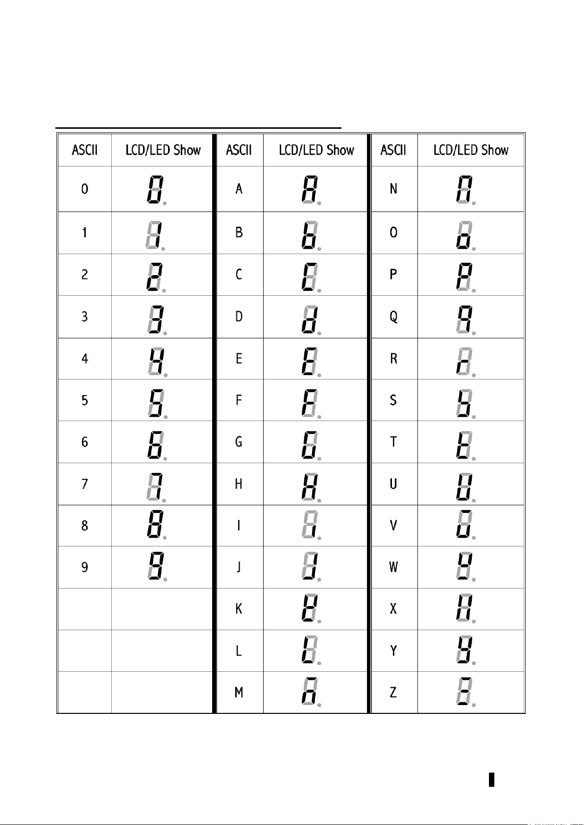
3. DISPLAY AND KEY DESCRIPTIONS
3.1 Indicator Display Character Definitions
244241,244242 www.globalindustrial.com . 3 .
Page 5

3.2 Overlay and key functions
KEYS
FUNCTIONS
Weighing mode
To turn the scale on or off.
To zero the scale if the display drifts from zero.
Parameter setting or
Calibration mode
To exit the current mode
Weighing mode
To tare the scale, if necessary.
Parameter setting or
Calibration mode
To confirm the input data or confirm the operation
To active accumulation function
To review the total accumulated value
Weighing mode
To toggle the weighing unit between Kg and Lb.
Enter Counting mode
Parameter setting or
Calibration mode
To increase the digit in the flashing data entry position by 1
Weighing mode
To print the weight details out to a PC or printer.
To lock the reading even if the person to be weighed is
moving.
Parameter setting or
Calibration mode
To shift the flashing data entry position from left to right
+
Weighing mode
To enter parameter setting mode
+
Weighing mode
To enter calibration mode
244241,244242 www.globalindustrial.com . 4 .
Page 6
3.3 Symbol meanings
DISPLAY
DESCRIPTIONS
Kg
Indicates when the scale is weighing in Kilograms.
Lb
Indicates when the scale is weighing in Pounds.
Indicates when the scale reaches zero.
NET
Indicates when the Net weight is displayed, Tare weight is at zero.
Indicates when the reading is stable
Hold
Indicates when the scale has held the weight reading shown on the display.
TOTAL
Indicates when the scale is display an accumulated value
PCS
Indicates when the scale is in counting mode
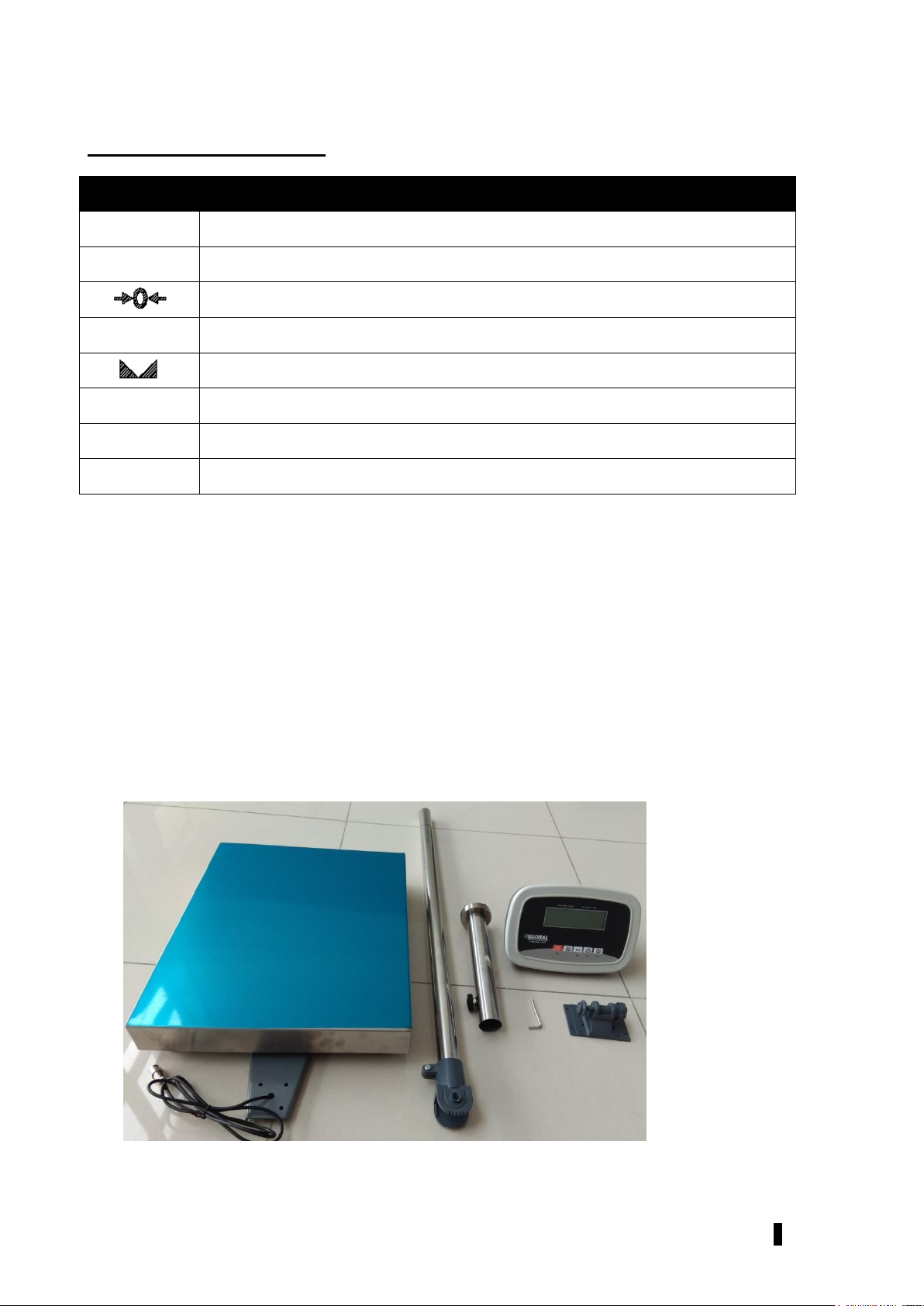
4. SETTING UP THE SCALE
The Platform Scale comes partially assembled. The following components require assembly:
Post
indicator
Tools required:
Phillips head screwdriver
Hexagon bar wrench (included)
1. Take all the contents out of the box.
244241,244242 www.globalindustrial.com . 5 .
Page 7
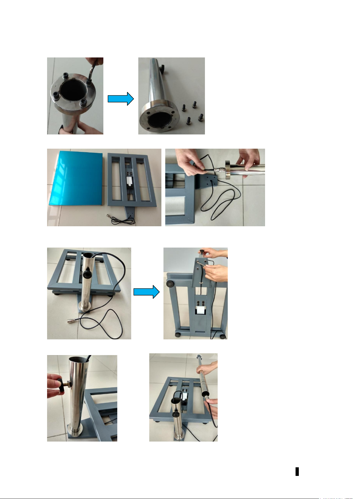
2. Remove the 4 inner hexangular set screws on the rear side of the shorter post.
3. Remove the stainless steel platter from the Insert the load cell cable through the short post.
4. Secure the post onto the bracket of scale base with the 4 inner hexangular set screws. Make sure
the screws are securely tightened.
5. Loosen the locker knob on the shorter post, then insert the cable through the longer post.
244241,244242 www.globalindustrial.com . 6 .
Page 8

6. Insert the longer post into the short post till reach or pass the black line marked on longer post, then
secure it by locking the knob.
7. Remove the 4 screws on rear side of the indicator, then disassemble the locking device on the
indicator bracket.
8. Insert the cable through the bracket, then lay the bracket on the post.
244241,244242 www.globalindustrial.com . 7 .
Page 9

9. Position the bracket in the slot to the direction desired. Lock the bracket.
10. Place the indicator on the bracket, and secure it with the 4pcs phillips screws.
11. Plug the female connector from load cell to the male socket on indicator.
Note: the connector is a snap-in connector, do not screw the female one into the male one, a
twisting force will cause inside wires to break.
12. Put the stainless steel platter back to the scale base, now the scale is ready to use.
244241,244242 www.globalindustrial.com . 8 .
Page 10

Yes
No
No
5. FUNCTION
5.1 WEIGHING
Normal Weighing
1. Power on the scale by pressing the key.
2. When the display stabilizes, but it doesn’t show zero, press the key to set a new zero point.
3. Place objects on the scale platform and read the weight on the indicator.
Note: Objects should be placed at the center of the platform. Corner or side loading heavy objects may
risk overloading an individual load cell and damage the scale.
4. To change the weight unit of measure, press the key.
5. Power off the scale by pressing and holding the key for 4 seconds.
Zero
If the display does not show 0, and there is nothing on the platter, press the key to zero the
reading.
The zero function is unavailable when the reading is out of the zero range and the indicator will show the
error message 0____ or 0ˉ ˉ ˉ ˉ, meaning the scale is over or under zero range.
Setting a Tare Weight
1. Zero the scale as described above.
2. Place an empty container on the platform, press the key. The display will return to zero,
eliminating the weight of the container. The NET announciator will be lit on the display.
3. Put the material or object to be weighed in the container. The net weight will be displayed.
4. To exit tare mode, remove all weight from the scale. The display will show a negative weight. Press
the key to return the display to zero.
244241,244242 www.globalindustrial.com . 9 .
Page 11

Hold Function
The Hold function is being used if you like to hold the results at the display after the weight/load has
been removed from the scale.
1. Press and hold the key for 4s while scale is under load.
2. “HOLD” announciator is on and the weight remains saved at the display after unloading the scale.
3. For deactivation of the Hold function, press and hold the key again.
5.2 COUNTING
1. In normal weighing mode, press and hold the key to enter into counting mode.
2. When the scale displays “SPL.—“, place the samples on scale, press the key to confirm.
3. “—“ will flash, then scale displays “00000”, use the and keys to input the quantity of the
samples, press the key to confirm. If any error occurs, the scale will display “SPL.Er” and
requires re-inputting the quantity.
4. Now put more parts on the scale for counting, the display will show the number of parts (pcs).
5. Press and hold the key to return to normal weighing.
5.3 ACCUMULATION
Accumulation can be used in both weighing and counting modes.
1. In normal weighing or counting mode, when reading is stable, press the key to accumulate
the current weight or quantity into memory, “TOTAL” announciator will be on and off in 2 seconds.
2. Remove the weight, allowing the scale to return to zero and put a second weight on. Press the
key, the display will show the new total.
3. To review the accumulated total, press and hold the key for 4 seconds, the scale will
display the total weight or quantity, “TOTAL” announciator will be on. After 2 seconds, the
nnounciator will be off and the scale will back to normal weighing or counting mode.
Note: In all cases the scale must return to zero or a negative number before another sample can be
added to the memory. More product can then be added by pressing the key. This can continue
until the total weight or quantity exceeds 999999.
244241,244242 www.globalindustrial.com . 10 .
Page 12

6. CALIBRATION
Before calibrating the scale, you should ensure that you have a known KG weight for calibration.
1. When in normal weighing mode with the scale at zero press and hold down and
keys to enter the calibration mode.
2. When the indicator shows ” CAL-?”, press the key to confirm and go to next step, or press
the key to exit the calibration mode.
3. Scale will display the max, capacity then display the division, press key to confirm and go
to next step or press the key to exit the calibration mode.
4. When “CAL.P0” is displayed, the scale will begin to calibrate the zero-point of the scale. Remove all
weight from the scale. Press the key to confirm, or press the to exit this mode.
After receiving the reasonable zero-point data, the scale will go to the next stepl automatically.
5. Now the scale displays “CAL.P1”, then displays a defaulted standard weight of 50%FS. Load
12.5%-100%FS weight on the scale, and use the and keys to input the loaded weight.
Press the key to confirm the input and go to next step. If an error occurred, the scale will
display “CAL.Er” and return back to step 4 for re-calibration.
6. When scale displays “CAL.P2”, then displays a default standard weight of 100% FS. Load
25%-100%FS (this must be equal or larger than the weight from the “CAL.P1”) weight on the scale.
Use the and keys to input the standard weight’s value. Press the key to confirm.
The indicator will flash the input weight and go to next step automatically. If an error occurred, the
scale will display “CAL.Er” and return back to step 4 for re-calibration.
7. When “CAL.P0” is shown again, the scale will calibrate the zero-point again. Remove any weight
from the scale, press the key to confirm, and back to the normal weighing mode. If an error
occurred in calibration, the scale will display “CAL.Er” and then it necessary to repeat the procedure
from step 4.
244241,244242 www.globalindustrial.com . 11 .
Page 13

7. USER PARAMETERS
Parameter
x/xy
Remark
244241
Setting
244242
Setting
P1.xy
00-15
Auto-off time:
No auto-off = 00.
01-15 minutes auto-off time.
05
05
P2.xy
00,01,02
0 = Only Hold Function
1 = Only Print Function
2 = both HOLD and PRINT function (pressed down less
3s,this key works as Print function; pressed down
more than 3s,this key works as HOLD function)
02
02
P3.xy
00-50
Hold function:
0 = disable hold function
1 = hold larger weight reading
2-50 = hold reading when the variety is within +2~50d,
auto release hold function when weight is below 10d and
auto-hold new stable weight (more than 10d)
02
02
P4.x
0-3
0 = No RS232 and USB Function.
1 = Press PRINT key to output display data when scale is
stable
2 = Press PRINT key to output gross, TARE and net
weight when scale become stable;
3 = Continuously outputs display data.
4 = continuously output gross, TARE and net weight;
5 = Output display data one time when scale is stable;
6 = Output gross, TARE and net weight one time when
scale become stable
7 = Bi-directional communication (the scale receives and
executes commands from the HOST device)
2
2
P5.x
0-4
Communication baud rate:
0=1200bps,
1=2400bps,
2=4800bps,
3=9600bps,
4=19200bps
3
3
1. When the scale is in normal weighing mode, press and hold the key and key for
3 seconds until ‘SEtUP’ is shown on the display.
2. In the SETUP mode, press the key to change the flashing digits, press the key to shift the
flashing data entry position from left to right, and press key to confirm and move to the
next parameter setting. Press the key to exit the set up mode.
Parameters setting summary:
244241,244242 www.globalindustrial.com . 12 .
Page 14

Parameter
x/xy
Remark
244241
Setting
244242
Setting
P6.x
0-2
Communication format: 0=8N1, 1=7O1, 2=7E1
0
0
P7.xy
00-32
Resolution select:
00=500, 08=2400, 16=7500, 24=35000,
01=600, 09=2500, 17=8000, 25=40000,
02=750, 10=3000, 18=10000, 26=50000,
03=800, 11=3500, 19=12000, 27=60000,
04=1000, 12=4000, 20=15000, 28=70000,
05=1200, 13=5000, 21=20000, 29=75000,
06=1500, 14=6000, 22=25000, 30=80000,
07=2000, 15=7000, 23=30000, 31=100000
32 = factory preset N (0<N<100000)
10
10
P8.x
0-2
Division select: 0=1, 1=2, 2=5
2
0
P9.x
0-5
Decimal point in calibration:
0= x1, 1= x0.1, 2= x0.01; 3= x0.001; 4= x0.0001; 5= 10
2
1
P10.x
0,1
Calibration unit: 0=kg, 1=lb
0
0
P11.x
0-6
Weighing units enable:
0=only kg; 4=kg or lb:oz;
1=only lb; 5=lb or lb:oz;
2=only lb:oz; 6=kg, lb, or lb:oz
3=kg or lb;
3
3
P12.x
0-7
Power-on zero-point range:
0=calibration zero -point +1%FS;
1=calibration zero -point +2%FS;
2=calibration zero-point +5%FS;
3=calibration zero-point +10%FS;
4=calibration zero-point +20%FS;
5=calibration zero-point +50%FS;
6=calibration zero-point +100%FS;
7=No limitation
7
7
P13.x
0-9
Zero range for ZERO button:
0= Power-on zero-point +1%FS;
1= Power-on zero-point +2FS;
2= Power-on zero-point +3FS;
3= Power-on zero-point +4FS;
4= Power-on zero-point +5%FS;
5= Power-on zero-point +10%FS;
6= Power-on zero-point +20%FS;
7= Power-on zero-point +50%FS;
8= Power-on zero-point +100%FS;
9= No limitation
6
6
P14.x
0-2
Weight signal is in power-on zero point range, Choose
which data as current power-on zero point:
0= current weight ;
1= calibration zero-point;
2=switch-off zero-point
0
0
244241,244242 www.globalindustrial.com . 13 .
Page 15

Parameter
x/xy
Remark
244241
Setting
244242
Setting
P15.x
0-3
Weight signal is not in power-on zero point range,
Choose which data as current power-on zero point:
0= current weight ;
1= calibration zero-point;
2=switch-off zero-point;
3=continuously display “0ˉˉˉˉ”
3
3
P16.x
0-8
Zero tracking range:
0=0d, no tracking;
1=+0.25d; 2= +0.5d; 3=+1d; 4=+1.5d;
5=+2d; 6=+3d; 7= +4d; 8=+5d
6
6
P17.x
0-3
Data filter intensity:
0=very weak, 1=weak, 2=middle, 3=strong
2
2
P18.x
0-9
Check weight stability range:
0=+0.5d; 1=±1d; 2=+1.5d; 3=+2d; 4=+3d;
5=+4d; 6=+5d; 7=+6d; 8=+7d; 9=+8d
1
1
P19.x
0-9
Overload limit range:
0=FS+0d; 1=FS+9d; 2=101%FS; 3=102%FS;
4=105%FS; 5=110%FS; 6=120%FS; 7=150%FS;
8=200%FS; 9=No limitation
1
1
P20.x
0-2
Backlight on-off mode selection (if it is installed):
0= Backlight is always off;
1= Backlight is always on;
2= Backlight is auto on and auto off. It is auto off after 10s
when scale goes to stable and has no key operation, and
it is auto on when scale is unstable or there’s some key
operation.
2
2
P21.x
0-4
LCD contrast level
3
3
244241,244242 www.globalindustrial.com . 14 .
Page 16

8. RS232/USB COMMUNICATIONS
8.1 RS-232 connection between the Scale and the Host:
Scale -----------------------Cable---------------------------Host
(DB9 female)-----(DB9 male)----(DB9 female)----(DB9 male)
PIN2 TXD 2 2 PIN2 RXD
PIN 3 RXD 3 3 PIN3 TXD
PIN 5 GND 5 5 PIN5 GND
PIN4 DSR 4 4 PIN4 DTR
PIN6 DTR 6 6 PIN6 DSR
PIN7 CTS 7 7 PIN7 RTS
PIN8 RTS 8 8 PIN8 CTS
PIN1 NC 1 1 PIN1 NC
PIN9 NC 9 9 PIN9
8.2 When Parameter P4.x in section 7 is set to 0 :
No RS232 and USB function. It will not transmit or receive any data although the scale is equipped with
RS232 or USB. The RS232 and USB function can be only activated when scale is in normal weighing
mode.
8.3 When Parameter P4.x in section 7 is set to 1 :
Output the current displayed data when the key is pressed, and it does not receive any data.
The output format is as below:
<LF>< reading, symbol, decimal point, weight unit><CR><EXT>
8.4 When Parameter P4.x in section 7 is set to 2 :
Output displayed gross, tare and net weight when the key is pressed, and it does not
receive any data. The output format is as below:
<LF>< Gross: Weight, symbol, decimal point, weight unit><CR><EXT>
<LF>< TARE: Weight, symbol, decimal point, weight unit><CR><EXT>
<LF>< Net: Weight, symbol, decimal point, weight unit><CR><EXT>
244241,244242 www.globalindustrial.com . 15 .
Page 17

The number of bytes used:
Weight reading ----------------------- 7bytes;
Symbol ----------------------------------1byte;
Decimal point -------------------------1byte;
Weight unit ----------------------------2 or 4 bytes;
8.5 When Parameter P4.x in section 7 is set to 3 :
Continuous output data when reading is stable, and it does not receive any data. The output format is
same as P4.1:
8.6 When Parameter P4.x in section 7 is set to 4 :
Continuous output gross, tare and net weight when reading is stable, and it does not receive any data.
The output format is same as P4.2:
8.7 When Parameter P4.x in section 7 is set to 5 :
Output displayed data one time when scale is stable, and it does not receive any data. The output
format is same as P4.1:
8.7 When Parameter P4.x in section 7 is set to 6:
Output gross, tare and net weight one time when scale is stable, and it does not receive any data. The
output format is same as P4.2:
8.8 When Parameter P4.x in section 7 is set to 7 :
1. The baud rate and data format is fixed as per P5 and P6 setting. Responses to serial commands will
be immediate, or within one weight measure cycle of the scale. One second should be more than
adequate for use as a time-out value by remote (controlling) device.
2. The length of the weight field will be 7 digit weight data, one for minus sign, one for decimal point,
two for measure unit (e.g. “lb”, “kg”). If the unit is lb:oz, another two for “lb” and one for a space
(<sp>) after lb. Units of measure abbreviations are always lower case.
3. If the weight is overcapacity, the scale will return nine ‘^’ characters (the field of symbol, decimal
point, weight data is filled by ‘^’).
a) If the weight is under capacity, it will return nine ‘_’ characters (the field of symbol, decimal point,
and weight data is filled by ‘_’).
b) If the zero point is error, it will return nine ‘_’ characters.
4. The character will be ‘-’ for negative weight or a space character for positive weight. Symbol, follows
after the first digit.
5. Useless leading zero before digits is suppressed
244241,244242 www.globalindustrial.com . 16 .
Page 18

8.9 Key to symbols used.
<LF> Line Feed character (hex 0AH)
<CR> Carriage Return character (hex 0DH)
<ETX> End of Text character (hex 03)
<SP> Space (hex 20H)
H1H2H3 Three status bytes. Refer to Table1 for definition.
<p> Polarity character including minus sign for negative weight and a space character for positive
weight
W1-W7 weight data
<dp> decimal point
U1U2: measure units, kg, lb
8.10 Commands and response
1. Command: W<CR> (57h 0dh)
Response:
①<LF>^^^^^^u1u2<CR><LF>H1H2H3<CR><ETX>---over capacity
②<LF>______u1u2<CR><LF> H1H2H3 <CR><ETX>---under capacity
③<LF>---------u1u2<CR><LF> H1H2H3<CR><ETX>---zero-point error
④< L F > < p > w 1 w 2 w 3 w 4 w 5 w 6 < d p > w 7 u 1 u 2 < C R > < L F > H 1 H 2 H 3 < C R >
<ETX> ---Scale is stable, and the current weight unit is kg or lb. With or without decimal point
and the position is as per the P9 setting and current unit.
2. Command: S<CR> (53h 0dh)
Response: <LF> H1H2H3<CR><ETX>
3. Command: Z<CR> (5ah 0dh)
Response: Zero function is activated and it returns to current scale status. just like pressing
ZERO/ON/OFF button:
<LF> H1H2H3<CR><ETX>
If ZERO function cannot be activated, it will return to current scale status.
244241,244242 www.globalindustrial.com . 17 .
Page 19

4. Command: T<CR> (54h 0dh)
Bit
Byte 1 (H1)
Byte 2 (H2)
Byte 3 (H3)
0
0=stable
0= not under capacity
01=normal work mode
10= hold work mode
00=not define
11= not define
1= not stable
1= under capacity
1
0= not at zero point
0= not over capacity
1= at zero point
1= over capacity
2
always 0
always 0
0= gross weight
1= net weight
3
always 0
always 0
always 0
4
always 1
always 1
always 1
5
always 1
always 1
always 1
6
always 0
always 1
always 0
7
parity
Parity
parity
Response: TARE function is activated, and then returns scale status. just like pressing TARE
button:
<LF> H1H2H3<CR><ETX>
If TARE function cannot be activated, it will return to current scale status.
5. Command: U<CR> (55h 0dh)
Response: Changes units of measure and return scale status with new units, just like pressing
UNIT button. The new measure unit should be allowed to use as per P11 setting.
<LF>u1u2<CR><LF> H1H2H3<CR><ETX>
6. Command: X<CR> (58h 0dh)
Response: power off the scale, just like press down the ON/OFF key to turn off the scale.
7. Command: all others
Response: Unrecognized command
<LF>?<CR><ETX>
Table1: The status bits definition:
244241,244242 www.globalindustrial.com . 18 .
Page 20

9. ERROR MESSAGES
1. 0ˉ ˉ ˉ ˉ ˉ zero point is over the setting range
2. 0_ _ _ _ _ zero is below the setting range
3. Adˉ ˉ ˉˉ ADC is over max. range
4. Ad _ _ _ _ ADC is below min. range
5. - - - - - - overload
6. CAL.Er there is an error in calibration
7. Lo.bAt the voltage of batteries or input power is below 5.6V.
10. WARNING
Do not dismantle the weighing machine without following the necessary instructions.
Do not jump while standing on the platform. This may damage the sensor inside.
Do not move the weighing machine violently and abruptly. It is recommended to move and
put down the weighing machine gently.
It is suggested to wipe the stains with soft cloth soaked with detergent and to wipe later with
soft cloth too. Do not use organic solutions and boiled water to wipe the stains. Do not use
water for cleaning.
Keep the weighing machine in a dry and clean environment. Do not expose it outdoor or use
it in locations near fire, under direct sunshine or with high temperature.
244241,244242 www.globalindustrial.com . 19 .
Page 21

11 Harbor Park Drive Port Washington, NY 11050
244241,244242 www.globalindustrial.com . 20 .
 Loading...