

Page 1
User's manual Manual del usuario Manuel de l'utilisateur
Customer Service
Servicio de atención al Cliente
US: 1-800-645-2986
Manual Chain Hoist
Models: 241638, 241639, 241640, 241641, 241642, 241643, 241644, 241645
Capacity - 0.5, 1, 1.5, 2, 3, 5, 10, 20 Tonne
Read this manual thoroughly prior to
installation, operation or maintenance.
Keep these instructions in a safe
location for future reference. For
questions, visit globalindustrial.com
or contact Customer Service at 1-800645-2982.
US: 1-800-645-2986
Service à la clientèle
Canada: 888-645-2986
Table of Contents
1. TECHNICAL DATA.....................................................................................2
2. APPLICATION..............................................................................................2
3. SAFETY INSTRUCTION............................................................................2
4. OPERATION INSTRUCTION......................................................................3
5. INSPECTION & MAINTENANCE...............................................................4
6. EXPLODED VIEW & PARTS LIST..............................................................5
1
012921
Page 2
User's Manual
Manual Chain Hoist
THANK YOU VERY MUCH FOR SELECTING OUR MANUAL HOIST!
This instruction manual describes the correct operating method to ensure prolonged service life. Please read
and completely understand this manual before operating the Manual Hoist. Always keep this manual at an
appropriate place. If the manual or warning decal is missing, please contact your vendor.
NOTE: All information reported herein is based on the data available at the time of printing. The factory
reserves the right to modify its own products at any time without notice or incurring in any sanction. Please
verify with the factory for possible updates.
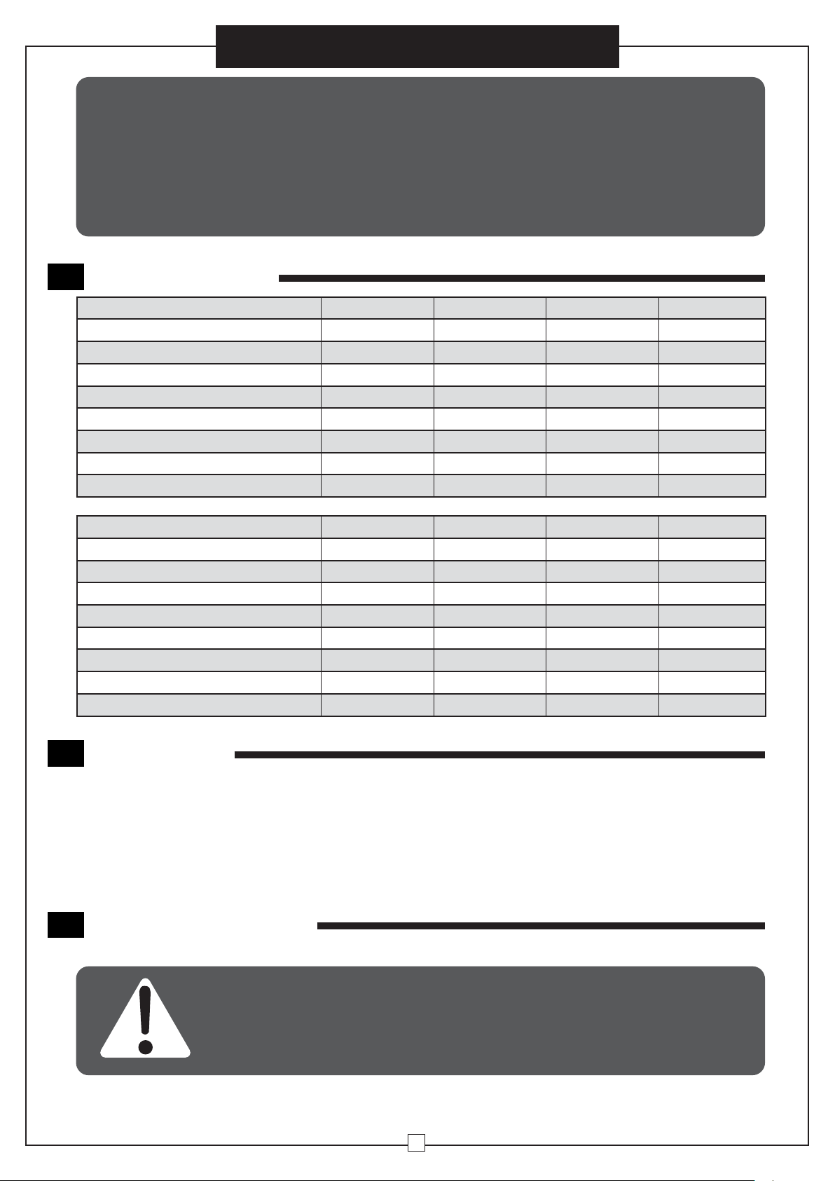
TECHNICAL DATA
1
Model
Lifting Capacity (tonne)
Standard Lift (m)
Testing Load (KN)
Head Room (mm)
Effort Force to Max. Load (N)
No. of Falls of Load Chain
Diameter of load Chain (mm)
Net Weight (kg)
Model
Lifting Capacity (tonne)
Standard Lift (m)
Testing Load (KN)
Head Room (mm)
Effort Force to Max. Load (N)
No. of Falls of Load Chain
Diameter of load Chain (mm)
Net Weight (kg)
241638 241642 241639 241643
1.0
3.0
12.5
300
310
1 1
Ø6 Ø6 Ø6
10
241640 241644 241641 241645
3
3.0
37.5
470
360
2 2
Ø8 Ø10 Ø10
21.7
1.0
12.5
300
310
14.9
3 5
6.0
37.5 62.5 62.5
470 600 600
360 400 400
Ø8
32.8
2.0
3.0 6.0
37.5
380
320
2
Ø6
13.5 21
3.0
2 2
35 50.6
2.0
6.0
37.5
380
320
6.0
2
5
APPLICATION
2
HCB Series Manual Hoist is a portable lifting device easily operated by hand chain. It is suitable for use in
factories, mines, farms, construction sites, wharves, docks and warehouses for installation of equipment, as
well as for loading and unloading goods. It is specially advantageous for lifting work in open air grounds and
places where no power supply is available.
The chain block can be attached to a trolley of any type as traveling chain block. It is suitable to monorail
overhead conveying system, hand traveling crane and jib crane.
SAFETY INSTRUCTION
3
WARNING Be sure each person reads and understands this manual before operating
or maintaining the hoist. The manual hoist must be properly operated and maintained
at all times. Do not operate this hoist with any power devices. The hoist is design for
manual operation.
2
Page 3

Manual Chain Hoist
• Do not exceed the rated load limit. Overloading may
cause hoist failure.
• Do not use power devices to operate the hoist, it is
designed for manual operation only.
• Do not attempt to repair the chain. Replace it with
new steel welded chain of the same size and strength.
• Lubricate the chain with good quality light oil or
chain oil before use.
• Do not lubricate the internal braking surfaces. The
brake must be kept dry.
• Make sure the load chain has no twists in the chain
sprocket, guide, and the vertical hanging length. If
there is a twist, disassemble and thread the chain
through the guide and chain sprocket.
• Make sure the load chain is attached to the loose
end pin before each use.
• Stand in the same plane or at the same angle as the
wheel when pulling the hand chain. Do not pull at an
oblique angle. Keep safe footing at all times.
• Do not lift loads over people. Do not allow anyone
to walk under the load. Warn personnel before lifting a
load.
• Do not use the hoist to lift people.
• Avoid off-center loading. Balance the weight evenly.
• Pull the hand chain steadily and smoothly to prevent
jerking or tangling.
• Seat the load firmly in the hook. Do not try to lift with
the tip of the hook.
• Do not wrap the chain around the load. Balance the
load weight evenly.
• Pull the lever handle steadily and smoothly to
prevent jerking or tangling.
• Raise the load only enough to clear the support
surface. Check for any malfunction or obstructions
before continuing the lift.
• If the chain jams or the lever handle cannot be pulled
any further, stop, inspect and correct the problem.
Do not try to force the hoist.
• Do not leave the load suspended in the air.
• Do not lower the load beyond the usable chain
length. Pulling the chain tight against the chain
sprocket will cause damage.
• Do not allow the load to contact the hoist. This will
block the swivel and may cause damage, twisted
chains, or a jammed wheel.
• Perform periodic inspection and maintenance.
Replace all damaged or malfunctioning parts.
• Test the hoist function thoroughly in both with
load or without load situation, before returning it to
normal operation.
• Do not touch the selector switch when the hoist is in
operation.
• Always lift./lower the load vertically.
OPERATION INSTRUCTION
4
4.1 To lift the load.
Pull the hand chain in a clockwise direction, rotating the
hand wheel in a clockwise direction. Pulling the hand chain
clockwise presses the friction plates and the ratchet disc
tightly against the brake seat, turning the drive shaft. The drive
shaft turns the spline gear, which transfers the rotation to the
disc gears, rotating the chain sprocket and smoothly moving
the load chain and hook upward.
4.2 Stopping the pull.
Stop the load movement and actuates the brake. The singleaction friction plates and ratchet disc press against the brake
seat, and pawl seats into the ratchet disc teeth.
Loose End Pin
Hand Chain
Load Chain
To lower hook
pull down on this
side of hand chain
Hand Chain
Load Chain
To raise hook
pull down on this
side of hand chain
4.3 To lower the load.
Pull the hand chain in a counterclockwise direction, rotating
the hand wheel releases the ratchet disc from the pawl,
allowing the friction plates and ratchet disc to separate from
the brake seat. The drive shaft turns the chain sprocket to
move the load hook downward.
3
Page 4

Manual Chain Hoist
5
INSPECTION & MAINTENANCE
5.1 Daily Maintenance
Hooks
1. Carefully inspect the hooks, and block attachments to the
hoist wheel and load chain.
2. Measure the hook throat openings. Replace if they are
stretched beyond the allowed maximum.
3. Inspect the hooks for distortion and stress cracks.
4. Make sure the hooks hang straight with a free swivel.
5. Inspect the hook latches for proper operation and
engagement. Do not use damaged or bent latches.
6. Replace all stretched, bent, or damaged parts. Lubricate the
attachments.
Chain
1. Examine the chain for adequate lubricant, excessive wear, foreign material, or twists before each use.
2. If the chain is twisted, rethread it through the sprocket and guides.
3. Lubricate the chain daily.
Brake
1. Check the brake operation for possible slippage before each use.
2. Keep the brakes dry. Do not allow oil or lubricant on the brake surfaces.
3. Repair or replace any damaged parts or worn friction discs.
Hoist
1. Inspect the chain sprocket and chain guides. Make sure the chain aligns properly.
2. Set the selector switch to neutral and pull the chain to make sure the chain and chain sprocket turn freely in both directions.
3. Lubricate the chain sprocket and guide rollers.
Opening
5.2 Annual Maintenance
WARNING To avoid injury or damage, allow only certified technicians to
disassemble and reassemble the hoist
Hooks
1. Carefully inspect the hooks, and block attachments to the hoist wheel and load chain.
2. Measure the hook throat openings. Replace if they are stretched beyond the allowed maximum.
3. Inspect the hooks for distortion and stress cracks.
4. Make sure the hooks hang straight with a free swivel.
5. Inspect the hook latches for proper operation and engagement. Do not use damaged or bent latches.
6. Replace all stretched, bent, or damaged parts. Lubricate the attachments.
Load Chain
1. Clean the chain with a neutral solvent and allow slack in the chain. Inspect the chain, link by link for nicks, gouges, or excessive
wear.
2. Pull the chain taut and measure throughout its length with a gauge, to identify twisted, bent or stretched links.
3. If any links are damaged, bent, stretched, or worn, replace the entire load chain with the same strength and type. DO NOT repair
the chain. The links are welded hardened steel and should not be individually repaired.
4. To replace the chain, thread the new chain through the chain sprocket and guide rollers, and attach to the loose end pin.
5. Lubricate the load chain thoroughly. Make sure the lubricant reaches the load bearing surfaces of the chain.
Hand Chain
1. Clean the hand chain and inspect for damage in the same manner as the load chain. Measure and gauge the total length to check
for stretched or bent links.
2. Cut damaged links from the chain. Purchase new unwelded connecting links. Do not use a cut chain link as a connector.
3. Connect the two end links with the new connector link, and close. If a connector link is opened and closed more than two times,
do not use it. Discard and use a new link.
Brake
1.
Inspect the brake components for glazing, wear, or lubricant on the friction discs. Check for scoring on the ratchet disc and brake seat.
2. Clean all brake parts with a neutral solvent. Make sure no lubricant is on any brake part. Keep the brake surfaces dry.
3. When replacing worn friction plates, discard to prevent re-use.
4
Page 5

Manual Chain Hoist
Ratchet and pawls
1. Inspect the ratchet teeth, pawls, pawl tips, and pawl studs. Check the springs for stretching, breaking, or corrosion.
2. Make sure the pawls move freely on the pawl studs. Lubricate the studs with WD-40
3. Look for signs of wear, or loose, broken, or missing parts. Replace and lubricate.
Chain sprocket and gears
1. Inspect the drive shaft, chain sprocket, gears, and roller bearings. Check for wear on all components.
2. Lubricate all threads, the chain sprocket, chain guides, gear train and all friction points.
3.
Use heavy grease at the gear train rotation points and rollers, to hold the parts while reassembling, and synchronize the gear timing.
4. Align the teeth of the two disk gears, the drive shaft and the splined gear, making sure the timing marks “0” of the disk gears are aligned
as shown.
5. After aligning the marks, place the end plate over the gear train and attach to the side plate.
Align
Timing
Marks "0"
CAUTION ! After internal maintenance and reassembly, test the hoist in load
and no-load conditions before returning to operation
6
EXPLODED VIEW & PARTS LIST
No. Description Qty. No. Description Qty.
1
Hand Wheel Cover 1
2
Hand Chain 1
3
Hand Wheel 1
4
Ratchet Disk 1
5
Friction Plate 2
6
Stripper 1
7
Brake Seat 1
8
Side Plate A 1
9
Bearing Race 2
10
Bearing Inner Ring 2
11
Chain Sprocket 1
12
Cylindrical Rollers A 60
13
Load Chain 1
14
Guide Roller 1
15
Pin 1
16
Stay A 1
17
Stay B 2
18
Splined Gear 1
19
Side Plate B 1
20
Disk Gear A Comb. 1
21
Cylindrical Roller B 48
22
Snap Ring 1
23
Driving Shaft 1
24
Gear Case 1
25
Disk Gear B Comb. 1
26
Sheet Cover 1
27
Label Set 1
28
Pawl Pin 1
29
Pawl Spring 1
30
Pawl 1
31
Snap Ring 2
32
Chain Pin 1
33
Latch Clamp 2
34
Bottom Hook Block 1
35
Hook 2
36
Top Hook Holder 1
37
Pinion Shaft 1
38
Slotted Nut 1
39
Split Pin 1
40
Headless Rivet 1
41
Spring 1
42
Stripper Pin 1
43
Spring Washer 1
44
Hex Nut 1
45
Hex Nut 1
46
Spring Washer 1
5
 Loading...