

Page 1

DARK1616S
DANTE NETWORK AUDIO
16 INPUT 16 OUTPUT AES3 & LINE LEVEL
ANALOGUE INTERFACE
PRODUCT DETAILS
6 BROOKS PLACE, MAIDSTONE, KENT, ME14 1HE. ENGLAND. TEL: +44 (0) 1622 753662
Visit our Website at www.glensound.co.uk FAX:
+44 (0) 1622 762330
Page 2

Glensound Electronics Ltd
Thank you for choosing a new Glensound product.
All rights reserved.
Information contained in this manual is subject to change without notice, if
in doubt please contact us for the latest product information.
If you need any help with the product then we can be contacted at:
Glensound Electronics Ltd
1 – 6 Brooks Place
Maidstone
Kent
ME14 1HE
United Kingdom
Telephone: +44 (0) 1622 753662
Fax: +44 (0) 1622 762330
EMAIL ADDRESSES
General enquires: [email protected]
Technical enquires: [email protected]
Sales enquires: [email protected]
Page 2 of 33
Page 3

PRODUCT WARRANTY:
All equipment is fully tested before dispatch and carefully designed to
provide you with trouble free use for many years.
We have a policy of supporting products for as long as possible and
guarantee to be able to support your product for a minimum of 10 years.
For a period of one year after the goods have been despatched the
Company will guarantee the goods against any defect developing after
proper use providing such defects arise solely from faulty materials or
workmanship and that the Customer shall return the goods to the
Company’s works or their local dealer.
All non-wear parts are guaranteed for 2 years after despatch and any
defect developing after proper use from faulty materials or workmanship
will be repaired under this warranty providing the Customer returns the
goods to the Company's works or their local dealer.
SAFETY WARNING
The DARK1616S contains no user serviceable parts and must not be
dissasembled in any way.
Page 3 of 33
Page 4

CE
EU DECLARATION OF CONFORMITY FOR:
DARK1616S
Sixteen channel AoIP, AES3/Analogue I/O interface
This declaration of conformity is issued under the sole responsibility of
the manufacturer.
This equipment is manufactured by Glensound Electronics Ltd of Brooks
Place Maidstone Kent ME14 1HE is CE marked and conforms to the
following Union harmonisation legislation:
Low Voltage Directive: EN60065 and EN62368-1:2014
Emissions: BS EN55032:2015
Immunity: BS EN55035:2017
Signed for and on behalf of Glensound Electronics Ltd.
Gavin Davis, Managing Director
Maidstone, Kent, England
Date: 21/03/2018
Page 4 of 33
Page 5

RoHS DIRECTIVE
Lead
0.1%
Mercury
0.1%
Hexavalent Chromium
0.1%
Polybrominated Biphenyls
0.1%
Polybrominated Diphenyl Ethers
0.1%
Cadmium
0.01%
EC directive 2002/95/EC restricts the use of the hazardous substances
listed below in electrical and electronic equipment.
This product conforms to the above directive and for this purposes, the
maximum concentration values of the restricted substances by weight in
homogenous materials are:
Page 5 of 33
Page 6

WASTE ELECTRICAL AND ELECTRONIC
EQUIPMENT REGULATIONS 2006 (WEEE)
Glensound Electronics Ltd is registered for business to business sales of
WEEE in the UK our registration number is:
WEE/JJ0074UR
Page 6 of 33
Page 7

GLENSOUND DARK1616S
Handbook Contents
Issue 3
Description Page No.
Contents
PRODUCT WARRANTY:................................................................................................................... 3
OVERVIEW ....................................................................................................................................... 8
DARK1616S FRONT PANEL LAYOUT .............................................................................................. 9
DARK1616S REAR PANEL LAYOUT .............................................................................................. 11
SIMPLIFIED BLOCK DIAGRAM ...................................................................................................... 14
CONNECTING THE DARK1616S TO A DANTE NETWORK ........................................................... 15
Getting Dante Controller ............................................................................................................... 15
Connecting DARK1616S To the Network ..................................................................................... 15
Audio Over IP Network ................................................................................................................. 15
Running Dante Controller ............................................................................................................. 16
Dante Controller TIP .................................................................................................................... 16
WINDOWS 10 REMOTE CONTROL APPLICATION ....................................................................... 17
GLENCONTROLLER App ............................................................................................................... 18
Running The App ......................................................................................................................... 18
Starting The App .......................................................................................................................... 18
App Controls ................................................................................................................................ 19
UPDATING FIRMWARE .................................................................................................................. 23
UPDATING THE BROOKLYN MODULE .......................................................................................... 28
AES67 MODE ................................................................................................................................. 29
WIRING INFORMATION ................................................................................................................. 32
Page 7 of 33
Page 8

OVERVIEW
The Glensound DARK1616S is an analogue to digital and digital to analogue
converter designed to connect AES3 and line level analogue audio circuits to a
Dante®/ AES67 audio network. The DARK1616S can also be synchronised with a
studio clock.
Dante® network audio is a common protocol for distributing high quality linear audio
over standard IP networks and it is widely used by many audio equipment
manufacturers. The DARK1616S Dante® audio interface is compatible with all
Dante® audio interfaces across all manufacturers. Further details of Dante® network
audio can be found at www.audinate.com
Intended for live on-air broadcast applications, the DARK1616S has been designed
with multiple redundancy capabilities. It has 2 mains power sources and it also has
fully redundant network connections for both Copper & Fibre circuits.
The DARK1616S provides 8 balanced AES3 inputs and 8 balanced AES3 outputs to
the Dante® network and 16 analogue line level (0dB) inputs to the Dante® network
and 16 analogue line level (0dB) outputs from the Dante® network. The rear panel
D25 connectors are wired to AES59 (also known as the Tascam standard).
The DARK1616S analogue and AES3 outputs are paired. When the same audio
signal from the Dante® network is presented on one channel’s AES3 output, it will
appear as an analogue audio signal on the equivalent analogue output.
For each channel only 1 audio input signal can be sent to the Dante® network, in
Auto mode the AES3 input has priority over the analogue, otherwise a source can be
selected using GlenControler.
GlenController is a Windows 10 application that allows parameters of the Dark1616S
to be confugured (such as input type and AES3 output clock source). It also allows
live metering of input and output channels.
Page 8 of 33
Page 9
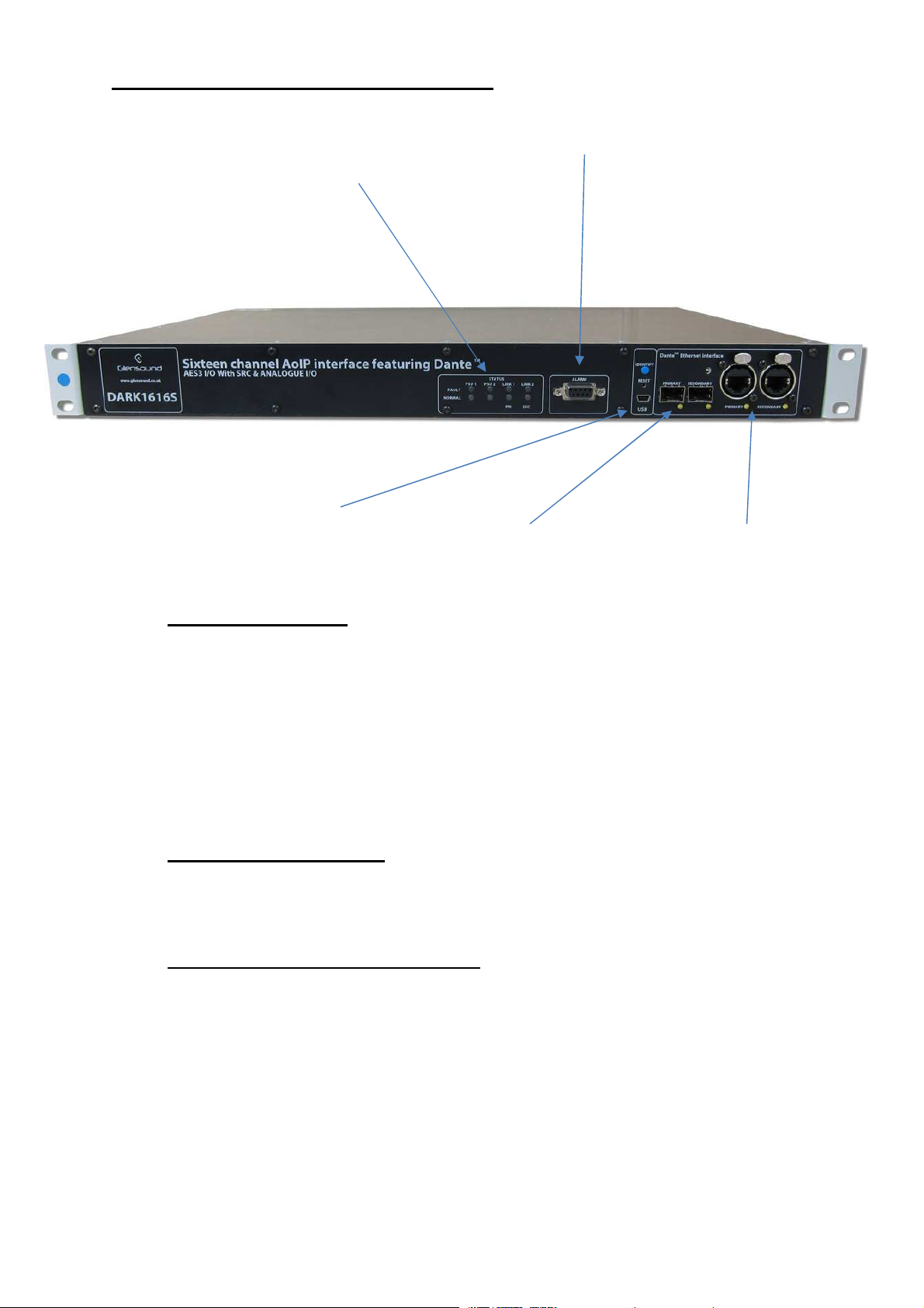
DARK1616S FRONT PANEL LAYOUT
1.
PSU and Link status
2. Alarm status connection
3. USB connector and
update buttons
4. Network SFP
connections
5. Network RJ45
connections
1. PSU and Link status
There are 4 red LEDs and 4 green LEDs that illuminate depending on the
status of the link. Red indicates no connection, green indicates a successful
connection.
For example, if you have connected the DARK1616S to two separate PSUs,
only one of which works then you will have a red ‘Fault’ LED illuminate to
warn you that there is no power detected on the connection that is not
receiving mains power.
2. Alarm status connection
This 8-way female D-type connector will report the failure of a link status if
one is detected whilst in operation.
3. USB connector and update buttons
The MINI USB connection allows the firmware of the DARK1616S to be
updated. To prepare the DARK1616S for a firmware update; power on the
unit, press and hold down the reset button, press and hold down the identify
button, release the reset button and then release the identify button a second
after.
Page 9 of 33
Page 10

4. Network SFP Connections
There are 2 standard network data SFP sockets provided to allow redundant
network connectivity if using Dante network audio protocol. They are both
gigabit network connections. They accept standard SFP modules. The status
LEDs flash to show when data is being correctly communicated with the
attached switch.
If you require SFP modules then please email [email protected] for a
quotation.
Network Note
Factory default is to have the SFP & RJ45 sockets set to work in redundant
mode.
It is possible using Dante controller to set these network interfaces to work as
a network switch instead of the redundant mode, meaning other network
equipment can be connected to them.
5. Network RJ45 connections
There are 2 standard network data RJ45 sockets provided to allow redundant
network connectivity if using Dante network audio protocol. They are both
gigabit network connections. The status LEDs flash to show when data is
being correctly communicated with the attached switch.
Page 10 of 33
Page 11
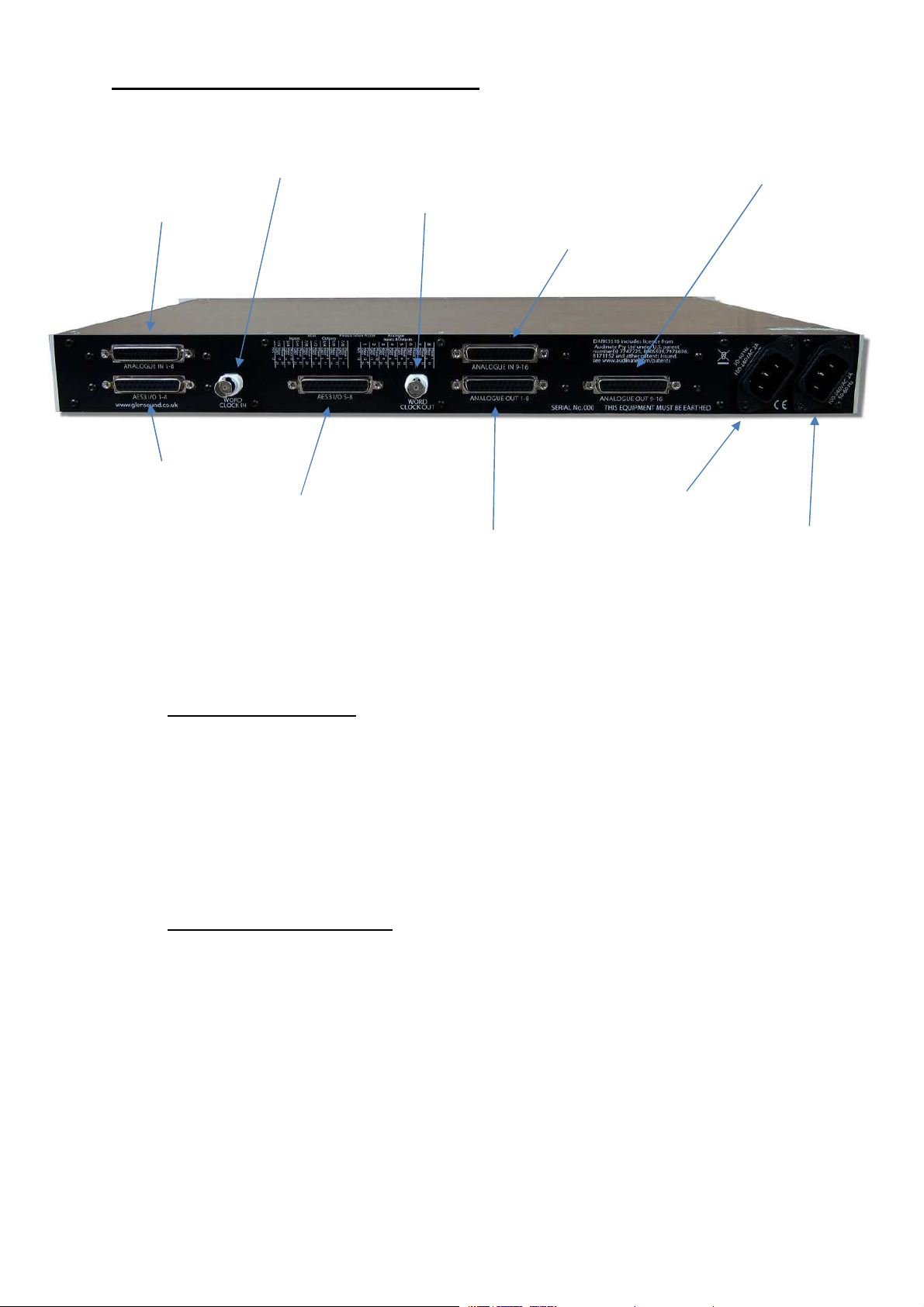
DARK1616S REAR PANEL LAYOUT
2.
AES3 inputs/outputs 1
- 4
6.
Analogue outputs 1
- 8
8.
Analogue outputs 9
- 16
9.
Primary IEC
Mains
3. Word clock IN
1. Analogue inputs 1 - 8
4. AES3 inputs/outputs 5 - 8
A detailed wiring table for the pins of all rear panel connections can be found at the end of the
manual.
1. Analogue inputs 1 - 8
A 25-way female D-type connector allows a breakout cable to be attached to
send analogue line level (0dB) signals in to the DARK1616S on channels 1 -
8. This connector is wired to AES59 standard (also known as the Tascam
standard).
The signals can then be routed via Dante to anywhere on a network or back
out of the DARK1616S via it’s analogue or AES3 digital outputs.
2. AES3 inputs/outputs 1 - 4
A 25-way female D-type connector allows a breakout cable to be attached to
send and receive 1 – 4 balanced digital AES3 signals. This audio can be
routed to anywhere on a network via Dante.
AES3 digital inputs signals always take priority over analogue inputs.
Therefore, sending an input to channel 1 in both digital and analogue domains
will result in the digital signal being accepted and the analogue signal being
disregarded.
Despite this, the DARK1616S will always ouput audio simultaneously to both
digital and analogue connections.
5. Word clock out
7. Analogue inputs 9 - 16
10. Secondary IEC Mains
Page 11 of 33
Page 12

3. Word Clock in
A BNC connector allows a studio clock signal to be sent to the DARK1616S.
This will enable the DARK1616S to synchronise it’s AES3 output sample rate
with the studio clock.
AES3 outputs will not work when the DARK1616S does not have a word clock
connected.
4. AES3 inputs/outputs 5 – 8
A 25-way female D-type connector allows a breakout cable to be attached to
send and receive balanced digital AES3 signals on channels 5 - 8. This audio
can be routed to anywhere on a network via Dante.
AES3 digital inputs signals always take priority over analogue inputs.
5. Word clock out
This BNC connector will output a clock signal that follows the rate of the AES3
outputs.
6. Analogue outputs 1 – 8
A 25-way female D-type connector allows a breakout cable to be attached to
send analogue audio signals out of the DARK1616S on channels 1 - 8. This
connector is wired to AES59 standard (also known as the Tascam standard).
The signals output from this connection can be audio received via the Dante
network.
7. Analogue inputs 9 – 16
A 25-way female D-type connector allows a breakout cable to be attached to
send analogue line level (0dB) signals from channels 9 - 16 in to the
DARK1616S. This connector is wired to AES59 standard (also known as the
Tascam standard).
The signals can then be routed via Dante to anywhere on a network or back
out of the DARK1616S via it’s analogue or AES3 digital outputs
8. Analogue outputs 9 – 16
A 25-way female D-type connector allows a breakout cable to be attached to
send analogue signals out of the DARK1616S on channels 9 - 16. This
connector is wired to AES59 standard (also known as the Tascam standard).
The signals output from this connection can be audio received via the Dante
network
Page 12 of 33
Page 13

9. Primary IEC Mains
The standard IEC mains plug accepts external AC voltages of 100 - 240 VAC
+/- 10%. There is a non-accessable internal fuse for this input.
The DARK1616S is designed to operate with either primary or secondary
mains sources or both for power redundancy.
10. Secondary IEC Mains
The standard IEC mains plug accepts external AC voltages of 100 - 240 VAC
+/- 10%. There is a non-accessable internal fuse for this input.
The DARK1616S is designed to operate with either primary or secondary
mains sources or both for power redundancy.
Page 13 of 33
Page 14
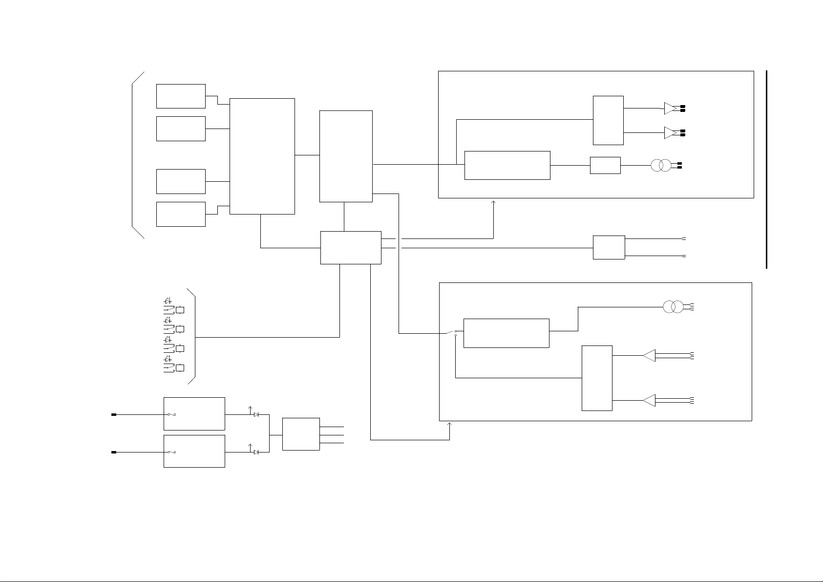
BI-DIRECTI ONAL
SIMPLIFIED BLOCK DIAGRAM
REDUNDANT
DANTE AUDIO
UP TO 192kH z
PRIMARY DANT E LINK STATE
REDUNDANT D ANTE LINK STATE
PSU 1 STATE
PSU 2 STATE
ETHERNET PH Y
COPPER
ETHERNET PH Y
FIBRE (SFP)
ETHERNET PH Y
COPPER
ETHERNET PH Y
FIBRE (SFP)
ETHERNET S WITCH
RELAY LOOP OUT PUTS & FRONT PANEL LED STATUS
DANTE FP GA
MICROCON TROLLER
1 OF 8 OF OUTPUTS
SRC
OUTPUT SAM PLE RATE
1 OF 8 OF INPUTS
AES3 RECE IVER & SRC
LINE OUT
DAC
LINE OUT
AES3 OUTAES TX
AES OUTPUT F REQUENCY = DANTE A UDIO FREQUENCY OR W ORD CLOCK FREQUENC Y
WORD CLOC K IN (BNC)
CLK GEN
WORD CLOC K OUT (BNC)
AES3 IN
LINE IN
ADC
TO MICRO
AC/DC PSU100 - 240 VA C
Page 14 of 33
AC/DC PSU100 - 240 VA C
+12VDC
+12VDC
TO MICRO
DC/DC
+12V
+3.3V
-12V
SOURCE SE LECTION
LINE IN
Page 15

CONNECTING THE DARK1616S TO A DANTE NETWORK
The DARK1616S is a network audio device utilizing the reliable and versatile Dante
audio over IP protocol. Dante is a widely used proprietary system made by Audinate.
For full details of the power of Dante network audio and instructions for using it, visit
www.audinate.com
Getting Dante Controller
If you are connecting the DARK1616S to a new Dante network the first thing you will
need to do is to get the free Dante controller software from Audinate.
This can be downloaded by visiting Audinate’s web site at www.audinate.com
Connecting DARK1616S To the Network
The DARK1616S can be connected to the network that you are going to use for your
audio distribution simply by plugging in either, and, or any of the network
connections on the front panel. Once connected to the network it will be possible to
see the DARK1616S from within the Dante controller and route its’ audio circuits.
Audio Over IP Network
We strongly recommend that you consider your network topology carefully and
would not recommend sharing broadcast audio and general data on the same
network.
For more details of audio over IP network structure please visit www.audinate.com
Page 15 of 33
Page 16
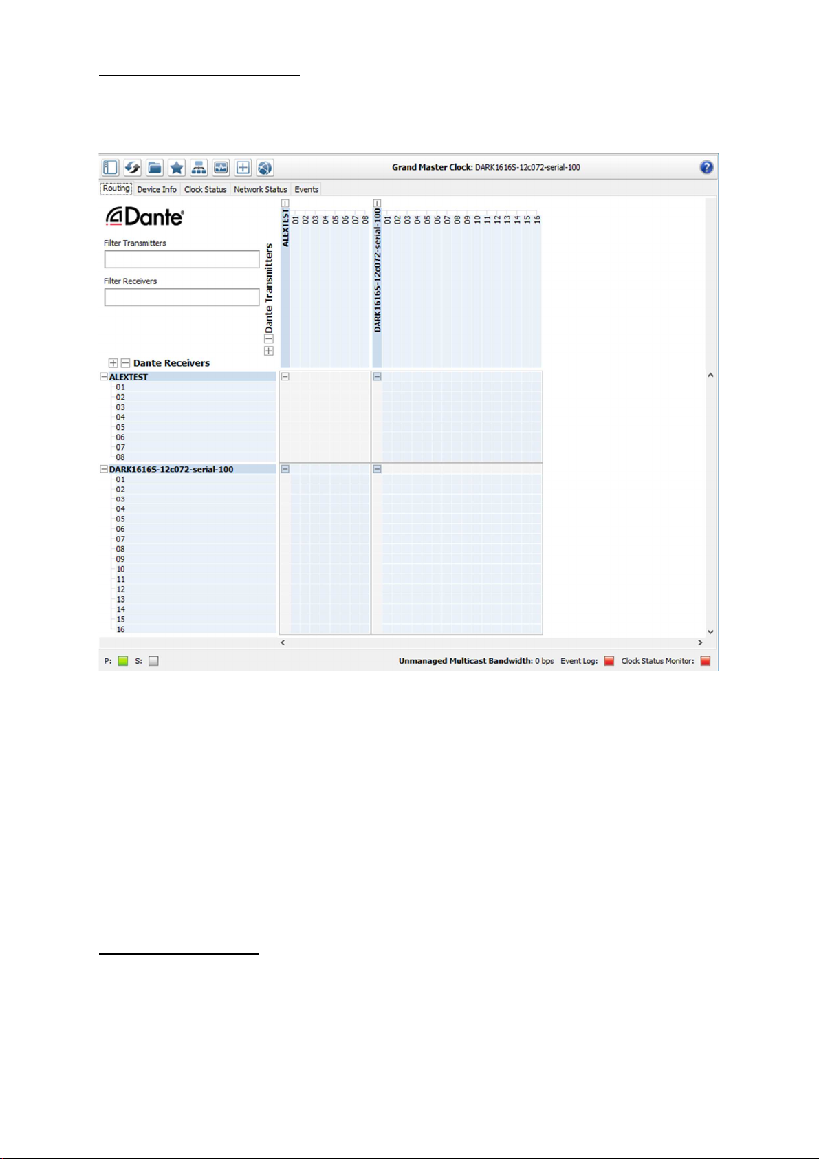
Running Dante Controller
At the time of writing this manual the Dante Controller looks as per the screenshot
below:
The DARK1616S will have been named at the factory during test to allow them to be
identified by the Dante controller.
The format used for the factory name is:
‘DARK1616S-12c072- serial-100’
Where ‘DARK1616S-12c072’ refers to the Glensound product and MAC address and
‘serial-100’ refers to the its serial number.
Dante Controller TIP
If you have never run Dante controller before then make sure that on the bottom left
of the Dante controllers’ screen ‘P’ or ‘S’ is next to a green square as this indicates
that it is connected to a network. By clicking ‘P’ or ‘S’ a pop up box opens to allow
you to set what network interface the controller is using.
Page 16 of 33
Page 17

WINDOWS 10 REMOTE CONTROL APPLICATION
1. General
A Windows 10 Application called GlenController is provided to allow configuration
and setup of the Dark1616S. It allows configuration items such as AES3 output clock
source and digital Fs levels to be set and also allows day to day operations such as
monitoring levels and selecting input sources.
GlenController is our own application that controls a number of different products.
2. Installing GlenController
Full details of the installation process and location of filers required to install
GlenController can be found on its web page:
http://www.glensound.co.uk/product-details/glencontroller/
3. Uninstalling GlenController
Find the app in the ‘All apps’ list then right-click and select ‘Uninstall’.
Page 17 of 33
Page 18
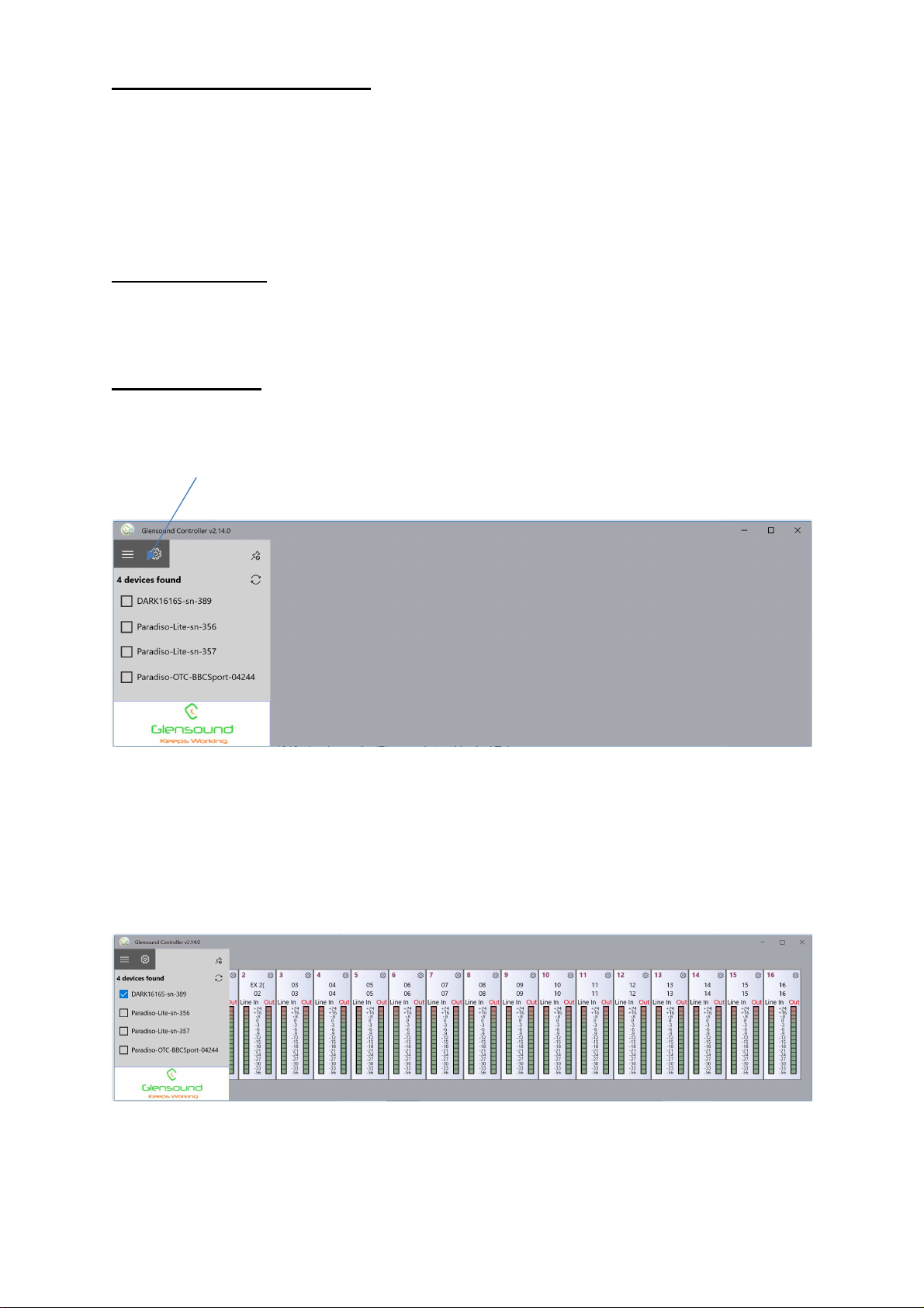
GLENCONTROLLER App
The Dark1616S has a remote control utility called GlenController. This app allows
the Dark1616S to be set up and controlled remotely, things such as clock source, Fs
level, filtering and metering can all be controlled/ seen via the app.
The below guide is meant as an indication of the facilities available on the app, but
being software developments are likely to be constantly evolving.
Running The App
To run GlenController, click the Windows icon in the bottom left corner of the screen,
and find it in the ‘All apps’ list and double click.
Starting The App
When the app first starts it looks for compatible devices across your network, and it
will show a list of any available units that it can connect to on the left hand side of the
screen.
Tick the box against the name of the device that you want to control and it will
appear in the main screen area:
Page 18 of 33
Page 19
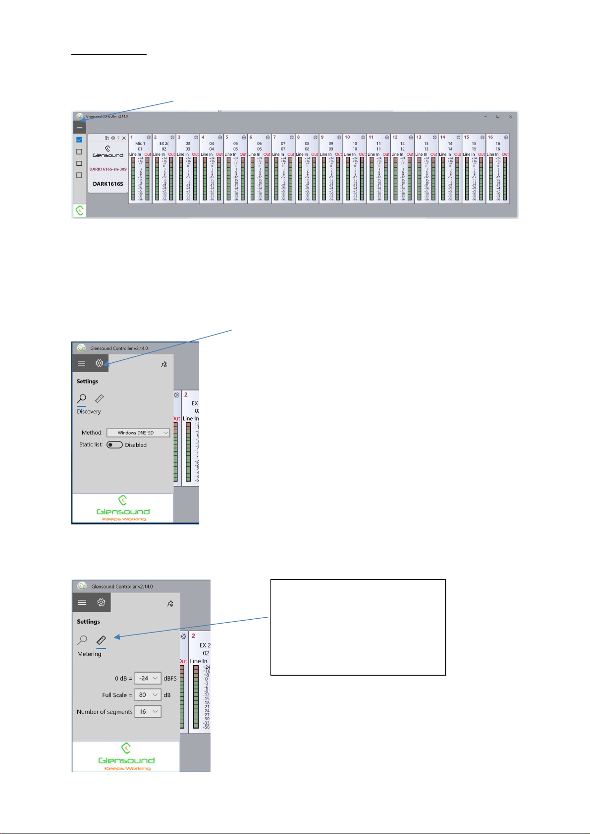
App Controls
Pressing this button toggles the side bar in and out:
Pressing the settings button provides in the ‘Discovery’ view different automatic
discovery methods and options for adding static ip addresses.
Discovery refers to the App discovering the Glensound hardware product(s) on your
network that it can provide remote control facilities for.
Pressing the Metering Icon in
the settings view opens
options for dBFs line up,
overall scale range (in dB)
and the number of segments
(resolution) of the meters.
Page 19 of 33
Page 20
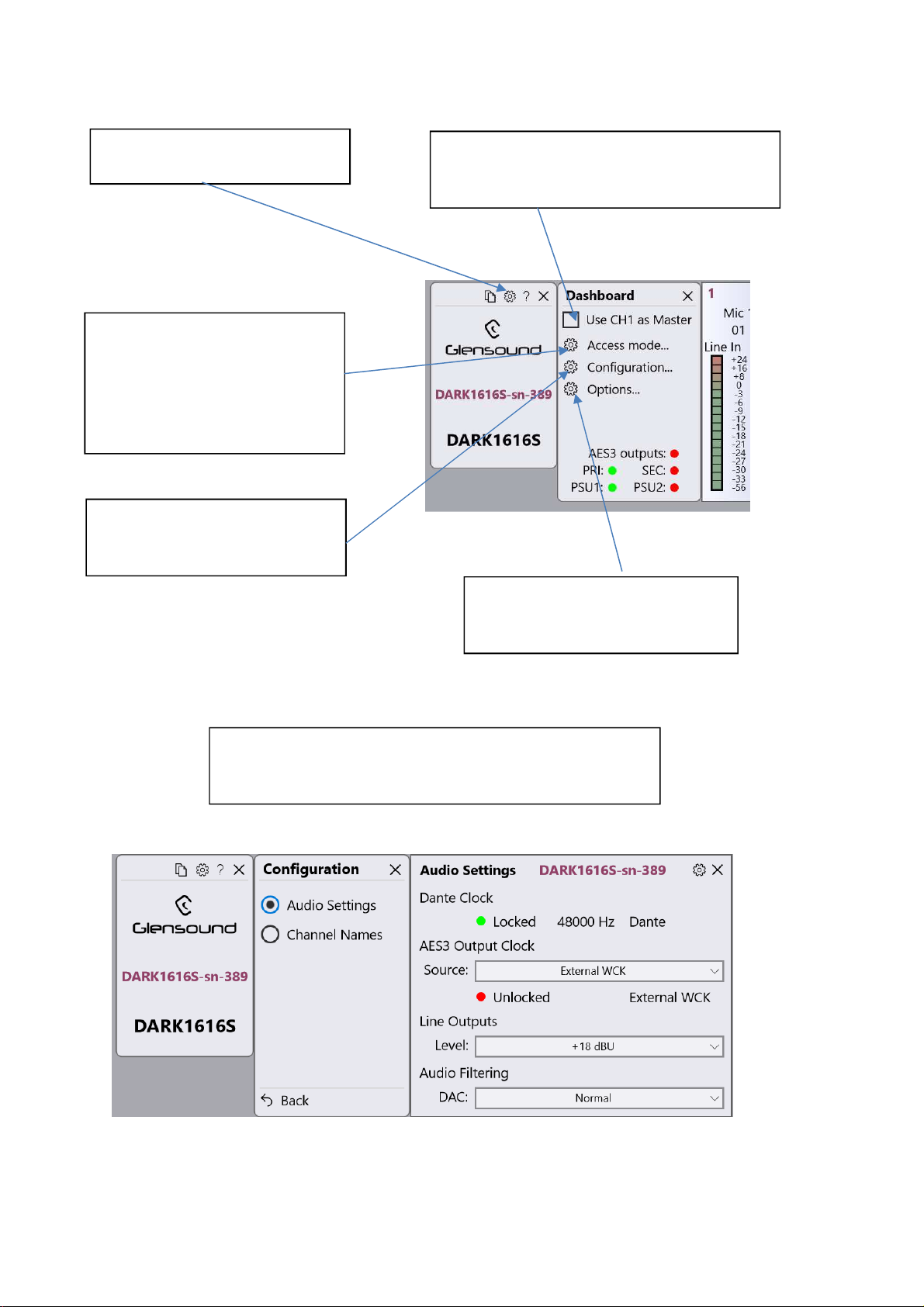
Pressing the settings button
opens up dasboard settings
Access mode setup allows
sole or shared control of the
Dark1616S by different PCs
running the App and the
control can also be
password protected
‘Use CH1 as Master’ if this tick box is
selected then when a change is made
to CH1 all other channels follow
Configuration opens up
further audio and channel
name options
In Audio Settings AES3 output clock source can be
set, Full scale (Fs) output levels can be set and
curent clock source and frequency can be seen
Options allows you set what
items such as meters are
shown in the channel view.
Page 20 of 33
Page 21
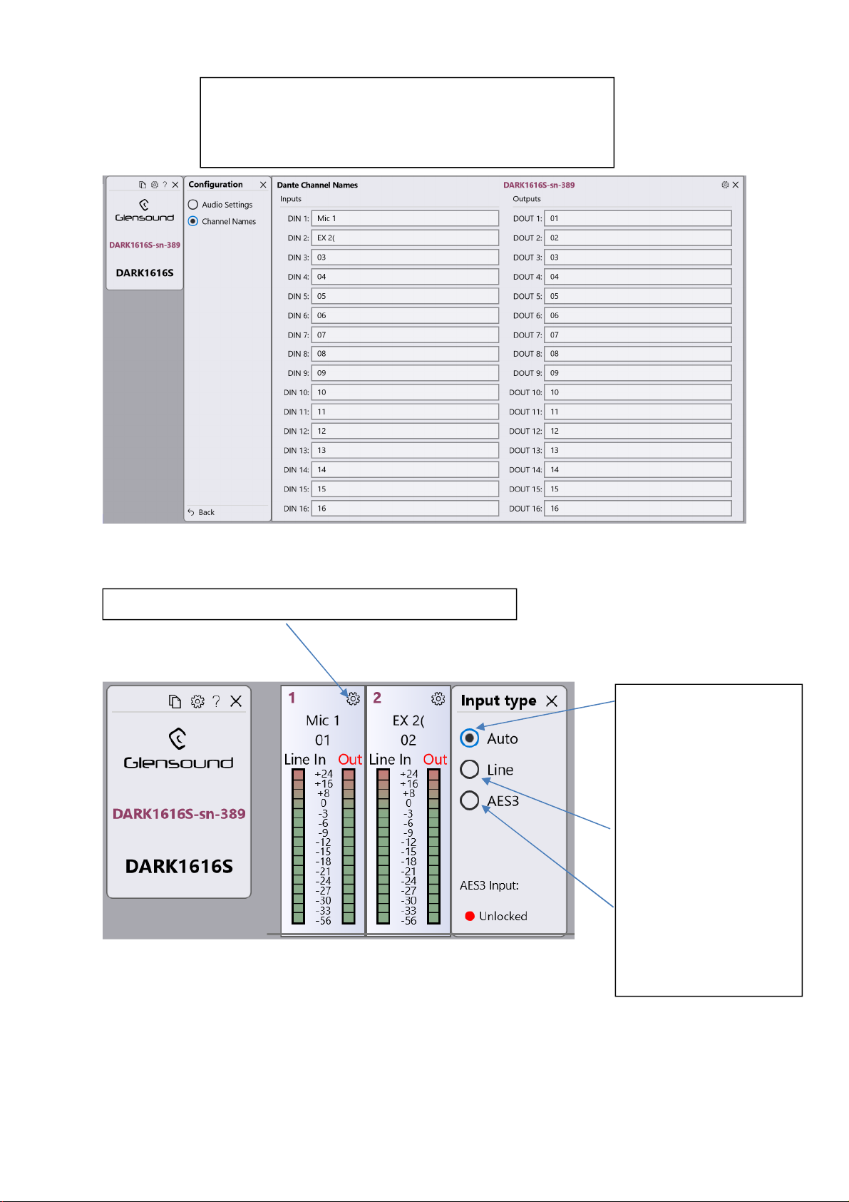
AUTO:
Changing Dante Channel Names allows names to
be changed that appear in the channel views of the
GlenController App and also the channel names
that appear in Dante Controller.
Select the settings Icon to open up more options
If a valid AES3 input
signal is present this
will be routed to the
Dante network
instead of the
analogue Line input.
LINE:
Analogue line input
will be routed to the
Dante network
AES:
The AES3 input
circuit will be routed
to the Dante network
Page 21 of 33
Page 22
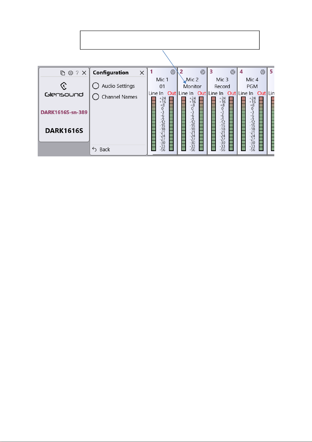
If Channel Names have been set then the top line shows the
Input Name and the bottom line shows the Output Name
Page 22 of 33
Page 23
UPDATING FIRMWARE
The DARK1616S is a complex digital audio system comprising of a DSP and several
Micro Controllers. All these items run software and may need to be occasionally
updated.
Equipment needed
A windows based PC
USB Type A to Mini B cable
A copy of ‘DfuSe Demo’ software
The latest firmware from Glensound
A DARK1616S and mains power
Instructions
1. Download and install DfuSE Demo
‘DfuSE Demo’ is a firmware updating tool that is required for loading new
firmware on to the DARK1616S.
It can be downloaded from the STMicroelectronics website found here:
https://goo.gl/AbzhsA. It is the file named “STSW-STM32080”.
Once you have downloaded this file you will need to extract the .exe
“DfuSe_Demo_V3.0.5_Setup.exe”, then run and install it.
2. Download firmware
The latest firmware for the DARK1616S can be found on the Glensound
website, under the product page for DARK1616S. Once you have
downloaded the file, place it in a folder or location of your choice.
3. Connect To A PC
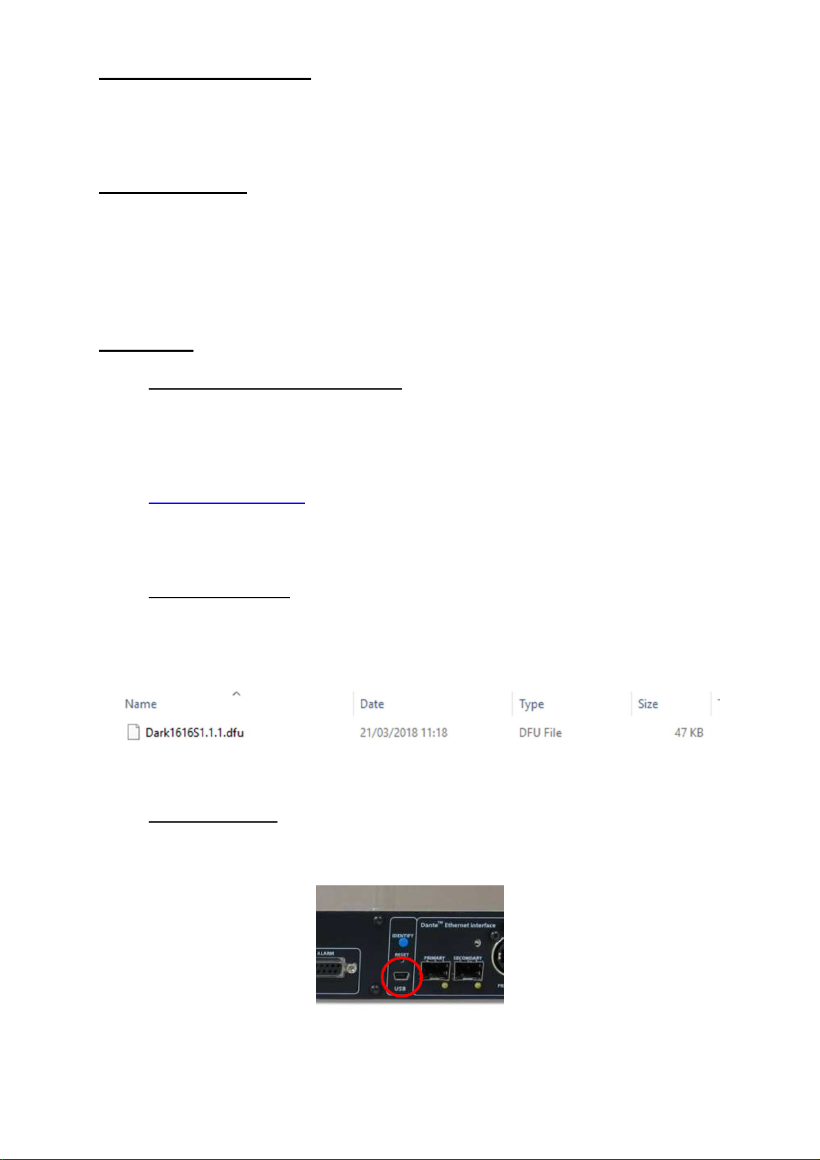
Connect the DARK1616S to the PC via the USB cable. The Mini USB
connector is located on the front panel of the DARK1616S.
Figure 1 Example filename
Figure 2 Front panel USB
connector
Page 23 of 33
Page 24
4. Firmware update preperation
To prepare the DARK1616S for a firmware update;
1. Power on the unit
2. Press and hold down the reset button
3. Press and hold down the identify button
4. Release the reset button and then release the identify button a second
after
Your PC should make an audible sound when this process is successful as
windows is detecting a new USB device.
5. Loading the firmware
Now open DfuSe Demo.
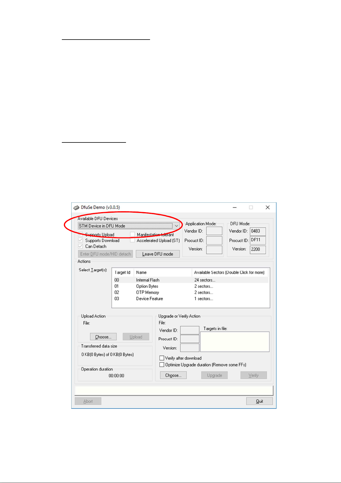
If the DARK1616S successfully entered DFU mode then it will appear as
‘STM Device in DFU Mode’ under the ‘Available DFU Devices tab’.
Figure 3 Device successfully recognised
Page 24 of 33
Page 25
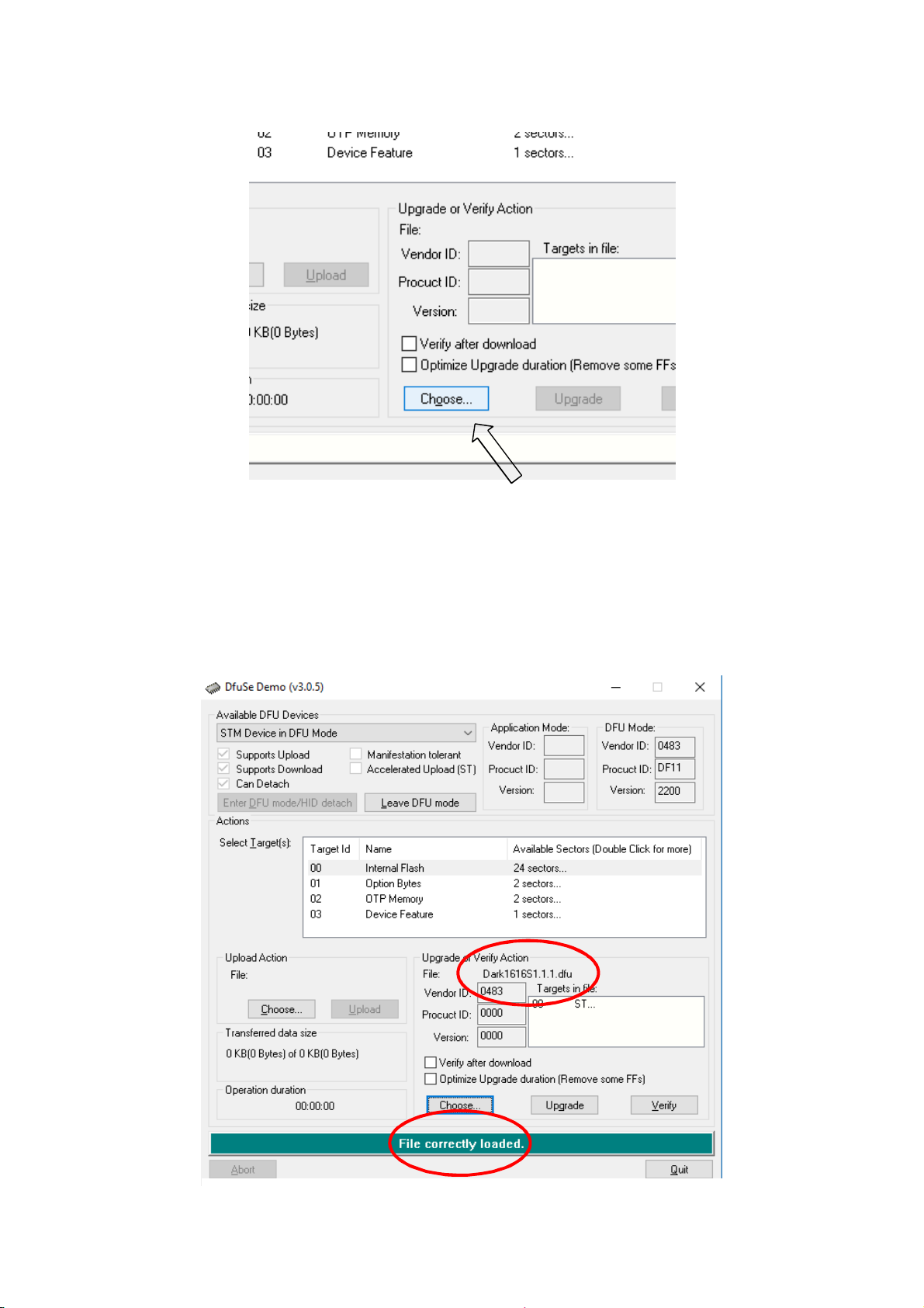
Now the .dfu file needs to be selected so that DfuSe Demo knows the correct
firmware to put on to the DARK1616S.
Figure 4 Choose .dfu file
Click choose and then select the .dfu file that you downloaded from the
Glensound website. This will be located in your downloads folder by default.
If the file loads successfully then it will read along the bottom ‘File correctly
loaded’.
Figure 5 .dfu successfully loaded
Page 25 of 33
Page 26
6. Upgrading the DARK1616S firmware
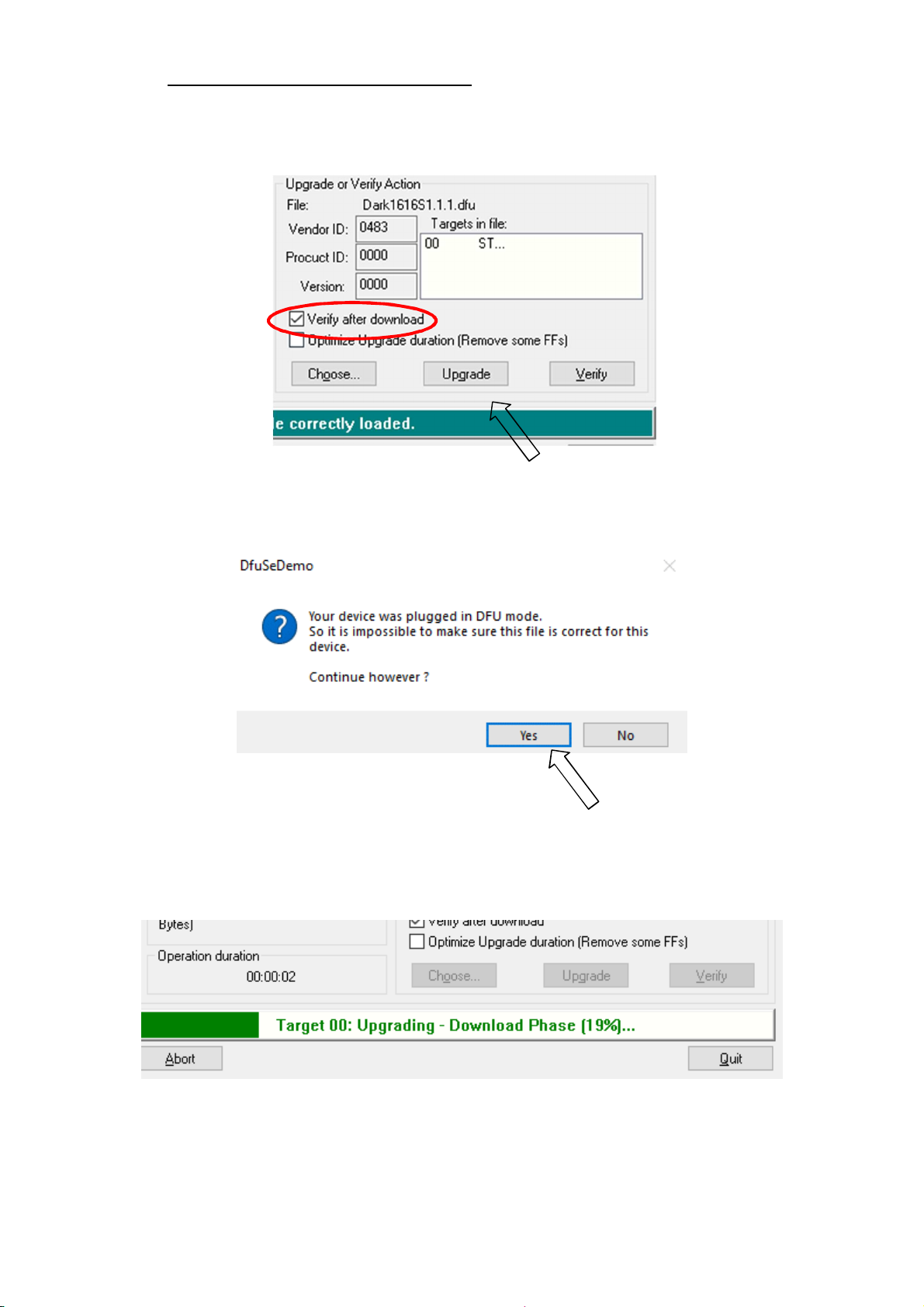
The firmware is now ready to be put on to the DARK1616S. Tick the ‘Verify
after download’ box first and then click ‘Upgrade’.
Figure 6 Upgrade
Click yes to proceed.
Figure 7 Start upgrade
The progress bar along the bottom will show the status of the operation.
Figure 8 Upgrade status
Page 26 of 33
Page 27
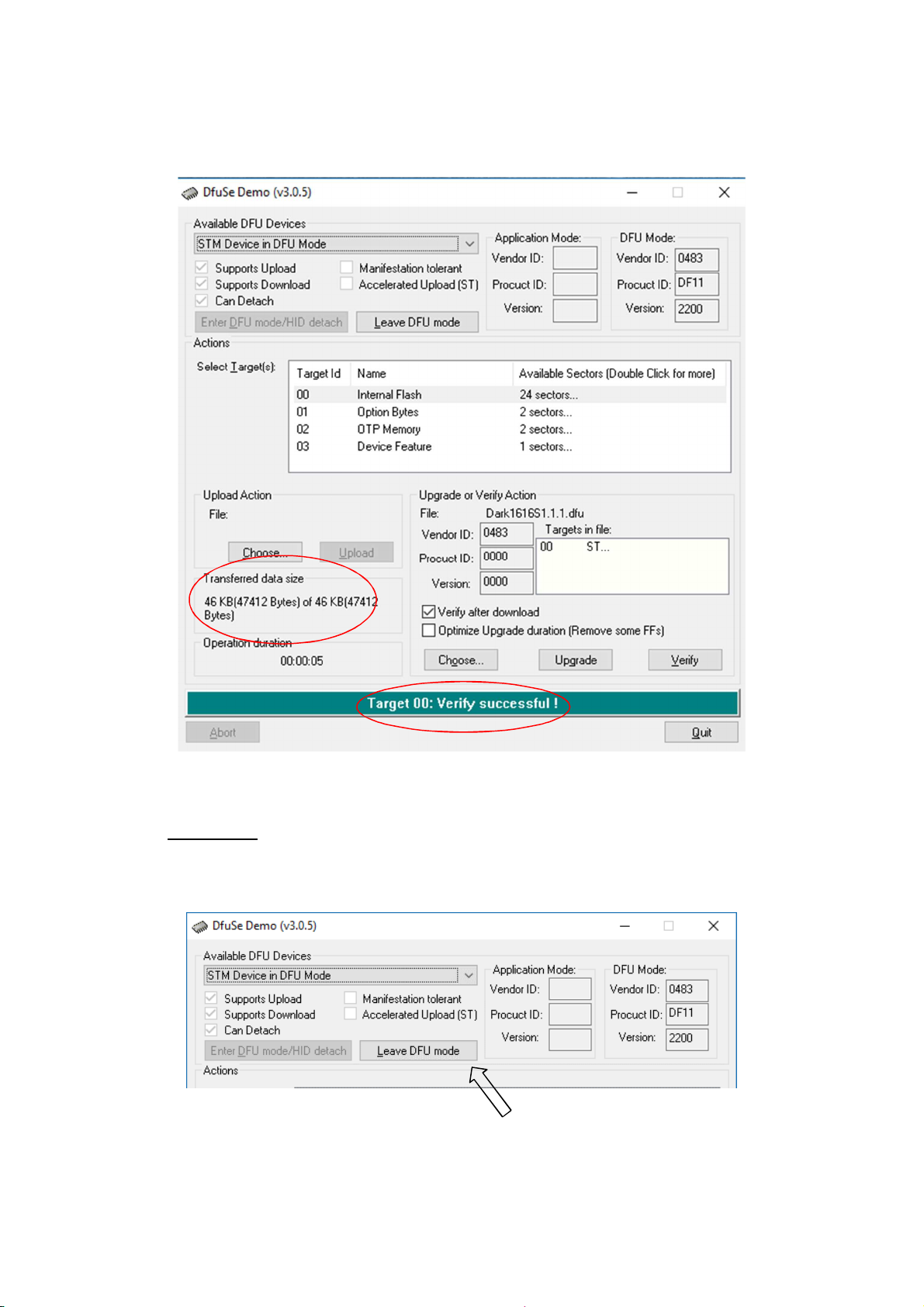
If the operation was successful, DfuSe Demo will report that “Targery 00: Verify
Successful!”.
You may also see that it will report how much data was successfully transferred.
7. Final steps
Now click “Leave DFU mode” to finish the procedure.
You may now disconnect the USB cable and continue to use the DARK1616S
with the freshly updated firmware!
Figure 9 Successful upgrade!
Figure 10 Final step
Page 27 of 33
Page 28

UPDATING THE BROOKLYN MODULE
The Brooklyn module is a device supplied by Audinate that does most of the
processing for the actual Dante/ AES67 network audio streams. There is one
Brooklyn module in each Dark1616M. We supply special code (a .dnt file) that sets
up/ initiates the Brooklyn module and makes it work in particular way and we also
run extra code on its internal microprocessor to make it work correctly with the
Dark1616M.
1. Finding Out Current Installed Version
Open Dante Controller.
Open Device Info tab.
Double Click in the device that you are working with….a new window will open called
‘Device View (name of device’
Open the status tab.
The Firmware Version (of the Brooklyn module) will be found under the ‘Device
Information’ heading.
2. Finding Out What The Latest Available Version Is
Go the Dark1616M’s web page at http://www.glensound.co.uk/product-details/dark1616m/ and open the ‘Firmware Latest Version’ Tab.
This will give both the latest version numbers/ file names and also the location to
download the file from.
3. Updating the Brooklyn Module
The firmware that runs on the Brooklyn module is updated using Audinate’s
Firmware updating tool. The updating tool and a user guide can be downloaded from
Audinate’s website:
https://www.audinate.com/products/firmware-update-manager
Please note we strongly advise that when you do the update that only your PC and
the Dark1616M that you want to update are on the network to save accidently
updating the wrong Dante device.
Page 28 of 33
Page 29
AES67 MODE
The Dark1616S uses a module from Audinate called a Brooklyn Module for its
network audio interface. Audinate are the company behind Dante
module’s primary network audio protocol is Dante, however Audinate have enabled
their module to comply with AES67 and therefore the Dark1616S can be set to
AES67 mode for interaction with other AES67 devices.
Please note however that Glensound are relying on Audinate’s AES67 interface and
are unfortunately not able to provide full AES67 support for the unit. AES67 support
should be sought directly from Audinate.
1. Turning On AES67 Mode
If you want to use your Dark1616S on an AES67 network and it has not been set to
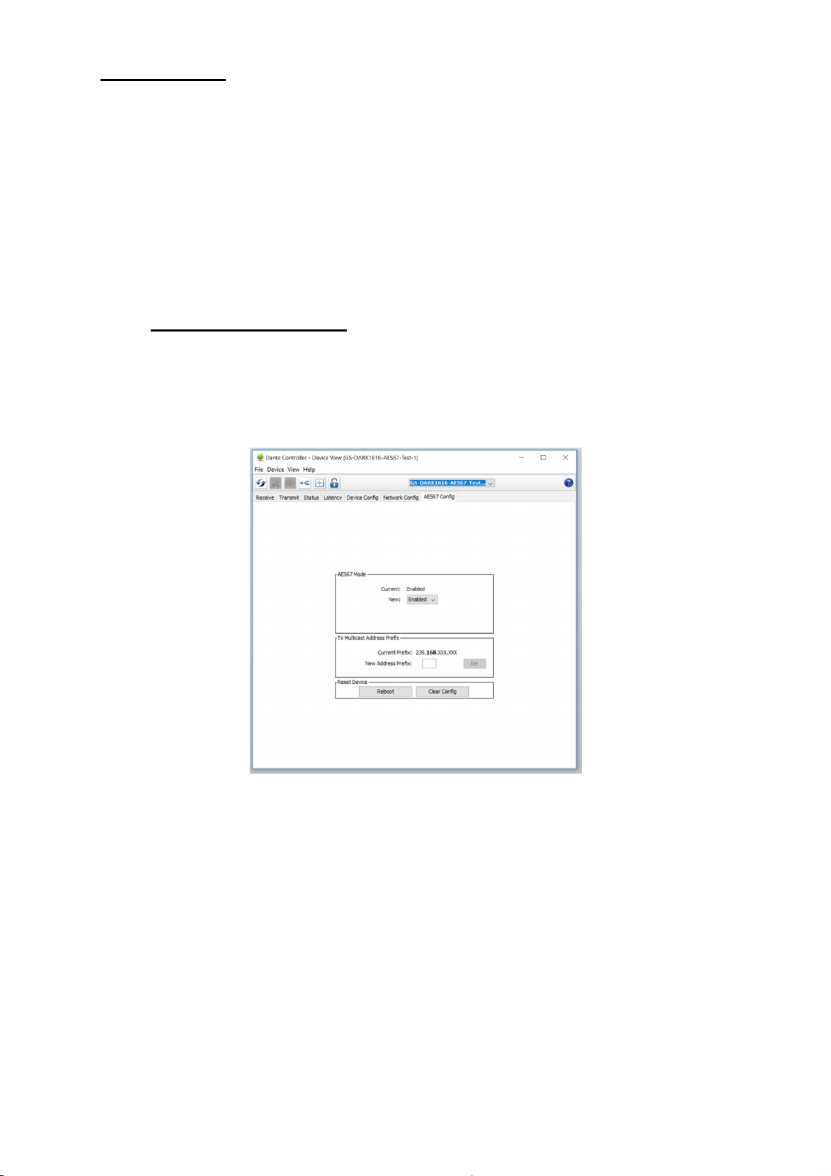
AES67 mode then this can be set in Dante controller by double clicking the
Dark1616S to open the Device View window where you will find an AES67 tab to
enable AES67 support.
®
and as such the
Once the AES67 drop down box has been enabled you’ll have to reboot the
Paradiso for the change to take effect. After the reboot go back to the AES67 tab
and set the multicast prefix address to one that is suitable for your newtork.
Page 29 of 33
Page 30
2. Sending AES67 Audio
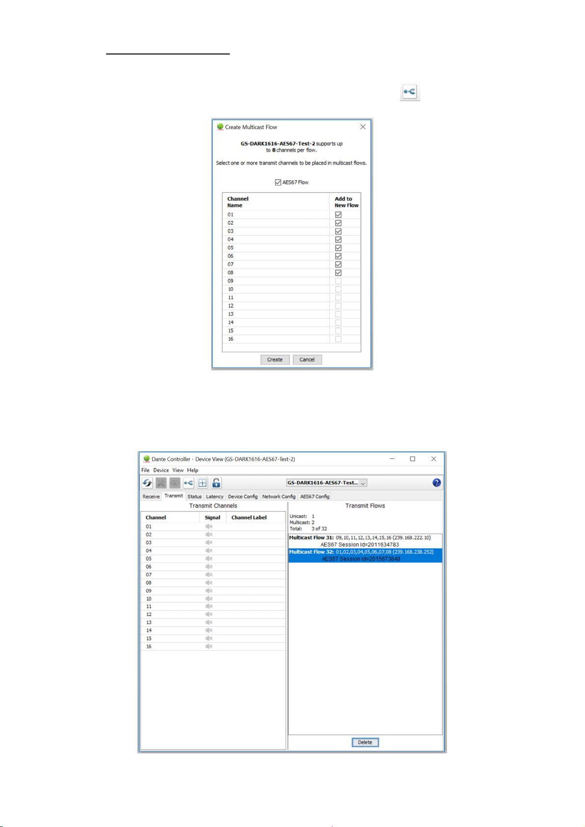
To transmit AES67 audio to the network a multicast flow must first be setup.
This is done by selecting the ‘Create New Multicast Flow’ Icon in the Device
View.
Tick the AES67 Flow check box, then select up to 8 channels to be included in the
flow then click ‘Create’
Once set the flows can be seen in the transmit tab of the device view.
Page 30 of 33
Page 31

3. Receiving AES67 Audio
Once a compatible AES67 stream is detected on the network by Dante Controller the
AES67 flows will appear in the Dante Transmitters section in the Routing tab.
4. AES67 Restrictions
AES67 flows can only be generated with the following constraints:
Multicast Only
Non-redundant
Destination address in range 239.nnn.0.0 to 239.nnn.255.255 (239.nnn/16),
port 5004
48kHz sampling rate
24 bit linear (L24) encoding
1 msec packet time
Up to 8 channels per stream
Received AES67 flows have the following constraints:
Multicast Only
Non-redundant
Destination address in range 239.nnn.0.0 to 239.nnn.255.255 (239.nnn/16),
port 5004. Must match destinatio address range.
48kHz sampling rate
L16 or L24 encoding
125usec, 250usec, 333usec, 1 msec packet time
Up to 8 channels per stream
Page 31 of 33
Page 32

WIRING INFORMATION
ANALOGUE AUDIO INPUTS 1
- 8
Input 1
Pins 24, 12, 25
In Phase, Mate, Ground
Input 2
Pins 10, 23, 11
In Phase, Mate, Ground
Input 3
Pins 21, 9, 22
In Phase, Mate, Ground
Input 4
Pins 7, 20, 8
In Phase, Mate, G
round
Input 5
Pins 18, 6, 19
In Phase, Mate, Ground
Input 6
Pins 4, 17, 5
In Phase, Mate, Ground
Input 7
Pins 15, 3, 16
In Phase, Mate, Ground
Input 8
Pins 1, 14, 2
In Phase, Mate, Ground
ANALOGUE AUDIO INPUTS 9
- 16
Input 9
Pins 24, 12, 25
In Ph
ase, Mate, Ground
Input 10
Pins 10, 23, 11
In Phase, Mate, Ground
Input 11
Pins 21, 9, 22
In Phase, Mate, Ground
Input 12
Pins 7, 20, 8
In Phase, Mate, Ground
Input 13
Pins 18, 6, 19
In Phase, Mate, Ground
Input 14
Pins 4, 17, 5
In Phase, Mate, Ground
Input 15
Pins 15, 3, 16
In Phase, Mate, Ground
Input 16
Pins 1, 14, 2
In Phase, Mate, Ground
ANALOGUE AUDIO OUTPUTS 1
- 8
Output 1
Pins 24, 12, 25
In Phase, Mate, Ground
Output 2
Pins 10, 23, 11
In Phase, Mate, Ground
Output 3
Pins 21, 9, 22
In
Phase, Mate, Ground
Output 4
Pins 7, 20, 8
In Phase, Mate, Ground
Output 5
Pins 18, 6, 19
In Phase, Mate, Ground
Output 6
Pins 4, 17, 5
In Phase, Mate, Ground
Output 7
Pins 15, 3, 16
In Phase, Mate, Ground
Output 8
Pins 1, 14, 2
In Phase, Mate, Ground
ANALOGUE AUDIO OUTPUTS 9
- 16
Output 9
Pins 24, 12, 25
In Phase, Mate, Ground
Output 10
Pins 10, 23, 11
In Phase, Mate, Ground
Output 11
Pins 21, 9, 22
In Phase, Mate, Ground
Output 12
Pins 7, 20, 8
In Phase, Mate, Ground
Output 13
Pins 18, 6, 1
9 In Phase, Mate, Ground
Output 14
Pins 4, 17, 5
In Phase, Mate, Ground
Output 15
Pins 15, 3, 16
In Phase, Mate, Ground
Output 16
Pins 1, 14, 2
In Phase, Mate, Ground
AES3 AUDIO INPUTS/ OUTPUTS 1
- 4
Input 1/2
Pins 24, 12, 25
In Phase, Mate, Grou
nd
Input 3/4
Pins 10, 23, 11
In Phase, Mate, Ground
Input 5/6
Pins 21, 9, 22
In Phase, Mate, Ground
Input 7/8
Pins 7, 20, 8
In Phase, Mate, Ground
Output 1/2
Pins 18, 6, 19
In Phase, Mate, Ground
Output 3/4
Pins 4, 17, 5
In Phase, Mate, Ground
O
utput 5/6
Pins 15, 3, 16
In Phase, Mate, Ground
Output 7/8
Pins 1, 14, 2
In Phase, Mate, Ground
AUDIO I/O D25 SOCKET PIN OUT
The wiring used for the DARK1616S conforms to AES59 (Also known as the Tascam
standard). Pre-made break out cables are available from a number of suppliers.
Page 32 of 33
Page 33

AES3 AUDIO INPUTS/ OUTPUTS 5
– 8
Input 9/10
Pins 24, 12, 25
In Phase, Mate, Ground
Input 11/12
Pins 10, 23, 11
In Phase, Mate, Ground
Input 13/14
Pins 21, 9, 22
In Phase, Mate, Ground
Input 15/16
Pins 7, 20, 8
In Phase, Mate, Ground
Output 9/10
Pins 18, 6, 19
In Phase, Mate, Ground
Output 11/12
Pins 4, 17, 5
In Phase, Mate, Ground
Output 13/14
Pins 15, 3, 16
In Phase, Mate, Ground
Output 15
/16 Pins 1, 14, 2
In Phase, Mate, Ground
ALARMS
PSU1 Failure NC
Pin 1 Closed Contact when PSU1 fails
PSU1 Failure NO
Pin 6 Open Contact when PSU1 fails
PSU2 Failure NC
Pin 2 Closed Contact when PSU2 fails
PSU2 Fa
ilure NO
Pin 7 Open Contact when PSU2 fails
LINK Primary Failure NC
Pin 3 Closed Contact when Primary link fails
LINK Primary Failure NO
Pin 8 Open Contact when Primary link fails
LINK Secondary Failure NC
Pin 4 Closed Contact when Secondary link fai
ls
LINK Secondary Failure NO
Pin 9 Open Contact when Secondary link fails
COMMON
Pin 5 Common for above (Internally linked to Ground)
ALARMS D9 SOCKET PIN OUT
Page 33 of 33
 Loading...