

Page 1

BEATRICE
B4, D4 & R4
4 Channel Network Audio Intercom
PRODUCT DETAILS
6 BROOKS PLACE, MAIDSTONE, KENT, ME14 1HE. ENGLAND. TEL: +44 (0) 1622 753662 Visit our Website at www.glensound.com FAX: +44 (0) 1622 762330
Page 2

Page 2 of 41
Glensound Electronics Ltd
Thank you for choosing a new Glensound product.
All rights reserved.
Information contained in this manual is subject to change without notice, if
in doubt please contact us for the latest product information.
If you need any help with the product then we can be contacted at:
Glensound Electronics Ltd
1 – 6 Brooks Place
Maidstone
Kent
ME14 1HE
United Kingdom
Telephone: +44 (0) 1622 753662
Fax: +44 (0) 1622 762330
EMAIL ADDRESSES
General enquires: [email protected]
Technical enquires: [email protected]
Sales enquires: [email protected]
Page 3

Page 3 of 41
PRODUCT WARRANTY:
All equipment is fully tested before dispatch and carefully designed to
provide you with trouble free use for many years.
We have a policy of supporting products for as long as possible and
guarantee to be able to support your product for a minimum of 10 years.
For a period of one year after the goods have been despatched the
Company will guarantee the goods against any defect developing after
proper use providing such defects arise solely from faulty materials or
workmanship and that the Customer shall return the goods to the
Company’s works or their local dealer.
All non-wear parts are guaranteed for 2 years after despatch and any
defect developing after proper use from faulty materials or workmanship
will be repaired under this warranty providing the Customer returns the
goods to the Company's works or their local dealer.
Page 4

Page 4 of 41
EU DECLARATION OF CONFORMITY FOR:
GS-BEATRICE B4, R4, D4
4 Channel Dante/ AES67 intercom
This declaration of conformity is issued under the sole responsibility of
the manufacturer.
This equipment is manufactured by Glensound Electronics Ltd of Brooks
Place Maidstone Kent ME14 1HE is marked and conforms to the
following Union harmonisation legislation:
Low Voltage Directive: EN60065 and EN62368-1:2014
Emissions: BS EN55032:2015
Immunity: BS EN55035:2017
Signed for and on behalf of Glensound Electronics Ltd.
Gavin Davis, Managing Director
Maidstone, Kent, England
Date: 15/03/2018
Page 5

Page 5 of 41
RoHS DIRECTIVE
EC directive 2002/95/EC restricts the use of the hazardous substances
listed below in electrical and electronic equipment.
This product conforms to the above directive and for this purposes, the
maximum concentration values of the restricted substances by weight in
homogenous materials are:
Lead
0.1%
Mercury
0.1%
Hexavalent Chromium
0.1%
Polybrominated Biphenyls
0.1%
Polybrominated Diphenyl Ethers
0.1%
Cadmium
0.01%
Page 6

Page 6 of 41
WASTE ELECTRICAL AND ELECTRONIC
EQUIPMENT REGULATIONS 2006 (WEEE)
Glensound Electronics Ltd is registered for business to business sales of
WEEE in the UK our registration number is:
WEE/JJ0074UR
Page 7

Page 7 of 41
GLENSOUND BEATRICE B4, D4 & R4
Handbook Contents
Issue 5
Description Page No.
Contents
PRODUCT WARRANTY: ................................................................................................................................................................ 3
OVERVIEW ........................................................................................................................................................................................ 8
FOUR AUDIO CHANNELS TWO NETWORK LOCATIONS ................................................................................................... 9
D4 PANEL LAYOUT ...................................................................................................................................................................... 10
Front & Rear Panels ................................................................................................................................................................ 10
R4 PANEL LAYOUT ...................................................................................................................................................................... 11
Front & Rear Panels ................................................................................................................................................................ 11
B4 PANEL LAYOUT ...................................................................................................................................................................... 12
Front, Rear & Side ................................................................................................................................................................... 12
FEATURES ....................................................................................................................................................................................... 13
CONFIGURATION MENU ........................................................................................................................................................... 16
FACTORY PRESETS ...................................................................................................................................................................... 25
AUDIO BLOCK DIAGRAMS (analogue representation of digtal circuits) .................................................................. 26
CONNECTING THE BEATRICE UNITS TO A DANTE NETWORK ...................................................................................... 28
Getting Dante Controller ..................................................................................................................................................... 28
Connecting Beatrice To The Network ............................................................................................................................. 28
Audio Over IP Network ......................................................................................................................................................... 28
Running Dante Controller ................................................................................................................................................... 29
Dante Controller TIP .............................................................................................................................................................. 29
Device Not Showing Up In Dante Controller ................................................................................................................ 30
AES67 MODE ................................................................................................................................................................................. 31
UPDATING FIRMWARE ............................................................................................................................................................... 34
UPDATING THE ULTIMO CHIPSET .......................................................................................................................................... 39
WIRING INFORMATION .............................................................................................................................................................. 40
XLR & JACK Wiring .................................................................................................................................................................. 40
Page 8

Page 8 of 41
OVERVIEW
This manual covers 3 very similar 4 channel BEATRICE IP intercom units. All 3 units
share a common internal DSP and Network interface card and all 3 also share the
same software.
The 3 units are:
BEATRICE B4: 4 Channel Beltpack
BEATRICE D4: 4 Channel Desktop
BEATRICE R4: 4 Channel 1RU Subrack
The BEATRICE range of IP intercoms was designed for broadcast, theatre and
professional audio applications.
Our Beatrice intercom system utilises the reliable and proven DanteTM network audio
transmission protocol to allow real time distribution of uncompressed audio across
standard networks. As such the BEATRICE 4 channel units are also fully compatible
with other manufacturers’ equipment using the Dante
TM
protocol. A future firmware
update will make the Beatrice AES67 compliant.
All units in the system are designed to be very easy to use for the operator and
simple to setup for the technician. They includes all the basic functionality required
for small intercom systems and none of the overly complex installation requirements
normally associated with large systems.
The name Beatrice was chosen for our intercom range as she was the love of Dante
Alighieri:
‘Dante had fallen in love with another, Beatrice Portinari (known as Bice),
whom he first met when he was only nine.’ Source Wikipedia.
Page 9

Page 9 of 41
FOUR AUDIO CHANNELS TWO NETWORK LOCATIONS
The 4 channel Beatrice units have a network audio interface chipset called ‘Ultimo’
that is supplied to Glensound under licence by Audinate (The Australian company
behind the brilliant Dante newtork audio protocol).
The Ultimo chipset is a 4 audio channel interface, however it has 2 fundemental
limitations.
1) 4 Outgoing Channels:
The chipset can only provide 2 Unicast outgoing circuits, to provide 4 outgoing audio
circuits 2 of the channels must be set to multicast.
2) 4 Incomming Channels:
Although 4 incoming audio channels can be received these can only be sent to the
Ultimo chipset from 2 discreet locations on the newtork as the chipset can only
receive 2 network data streams.
Page 10
Page 10 of 41
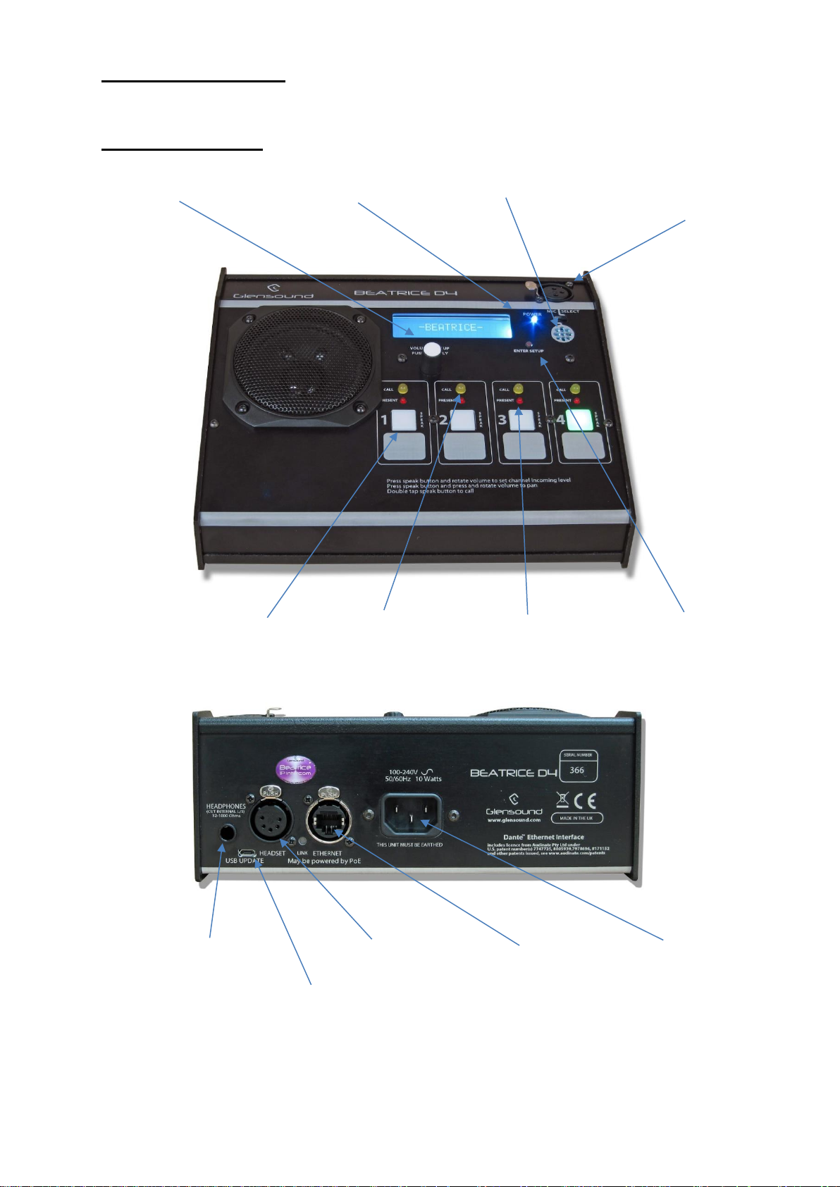
D4 PANEL LAYOUT
Front & Rear Panels
Volume/ Setup Knob
Power On LED
Panel
Microphone
External
Microphone Input
Audio Presence LED
Call Light
Speak Key
Headphone
Jack
Headset
Connector
Network
RJ45
USB Update
IEC Mains
Enter Setup
Page 11
Page 11 of 41
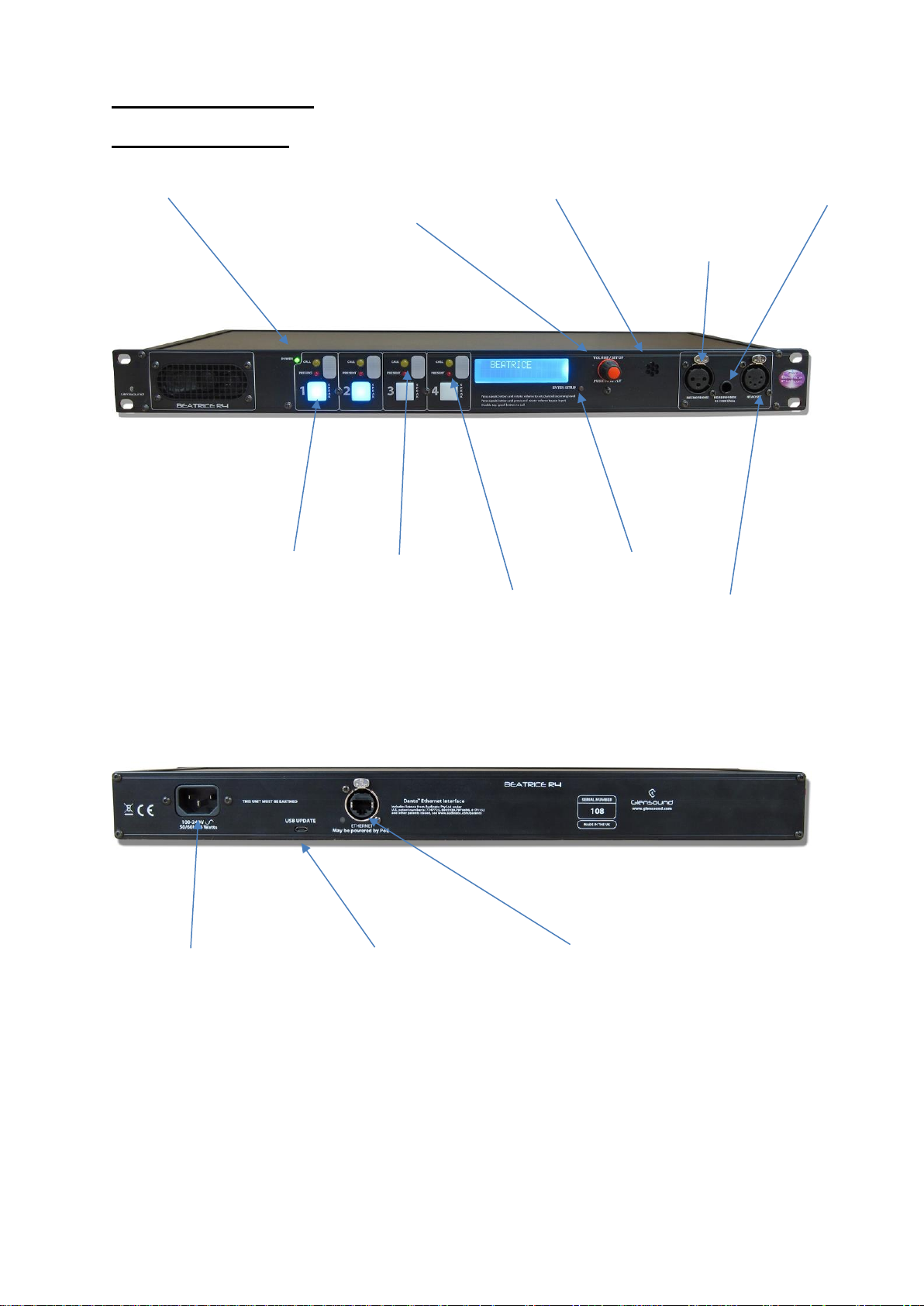
R4 PANEL LAYOUT
Front & Rear Panels
Power On LED
Volume/ Setup
Knob
Panel
Microphone
External
Microphone Input
Audio Presence LED
Call Light
Speak Key
Network
RJ45
USB Update
IEC Mains
Enter Setup
Headset
Connecto
r
Headphone
Jack
Page 12
Page 12 of 41
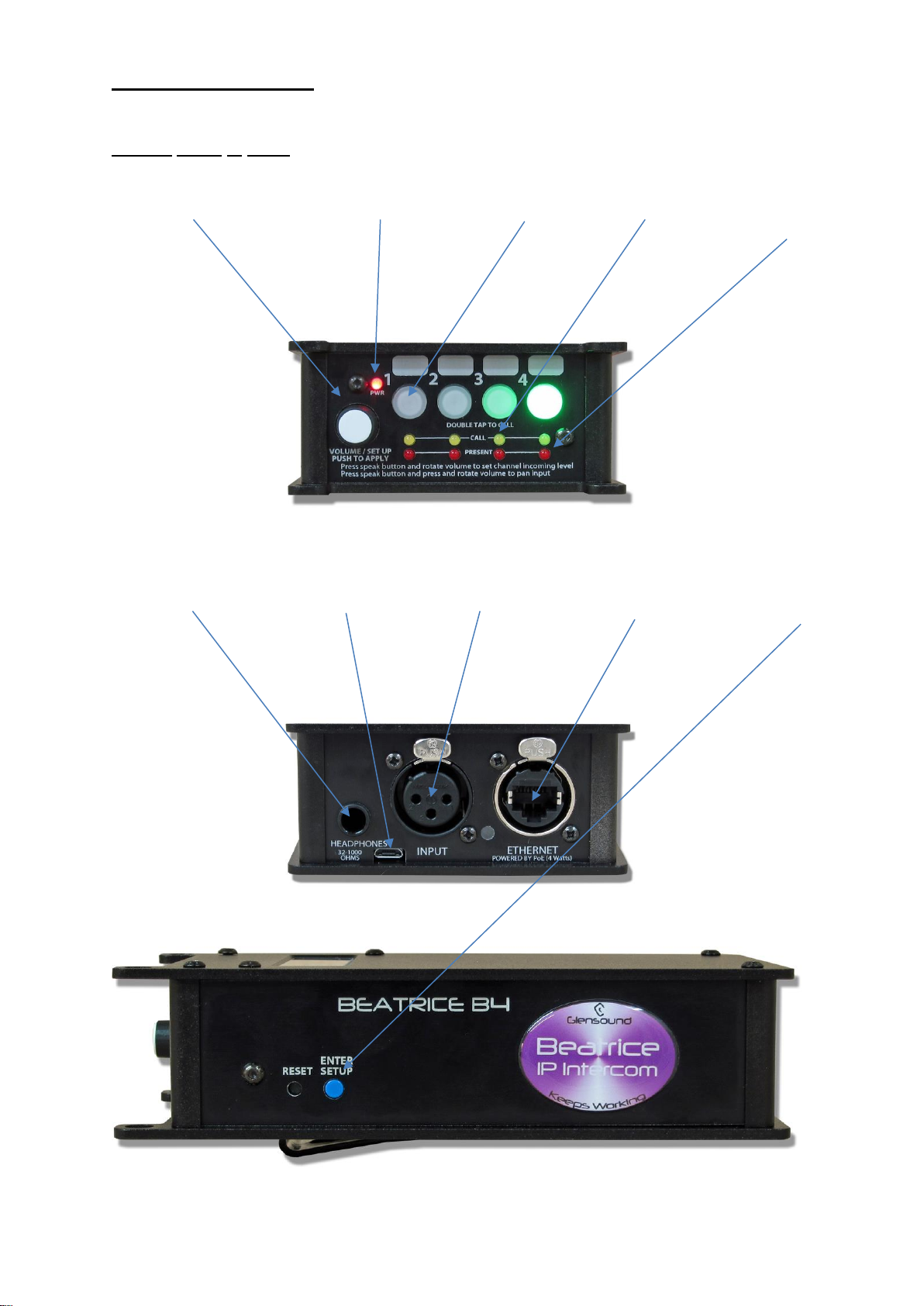
B4 PANEL LAYOUT
Front, Rear & Side
Volume/ Setup Knob
Power On LED
Talk Keys
Call Light
Audio
Presence LED
Headphone
USB Update
Microphone
Network RJ45
Enter Setup
Page 13

Page 13 of 41
FEATURES
1. Volume/ Setup Knob
This multi-function knob provides several different functions depending upon
whether the user is in setup mode or not.
In Normal Mode there are 3 functions:
A) Rotating the control increases / decreases the loudspeaker/ headphone
volume.
B) Simultaneously pushing the knob in and rotating it while pressing a speak
key will pan the associated incoming audio circuit between left/ right ears.
C) Simultaneously pressing a speak key and rotating the knob will increase /
decrease the input gain of the associated incoming circuit.
In Setup Mode:
The knob is used to enter menus and change parameters. This is done by
rotating the knob until the desired menu is seen on the display, then push the
knob and the menu will be accessed, rotate the knob again to select the
desired setting and press the knob in to select and save that setting.
2. Power On LED
The power on LED indicates that the device is powered on and the internal
microprocessor is working correctly.
3. Panel Microphone
Note: This feature is not fitted to the Beltpack B4.
The panel microphone is a small electret microphone fitted behind the front
panel and is suitable for most communications purposes.
4. External Microphone Input
This is a balanced microphone input. It can accept dynamic and condenser
microphones and phantom power (48v) can be turned on/ off in the menu
system. The gain of this input is also adjusted in the menu system.
5. Speak Key
These multifunction keys can operate in a number of different ways. In
general terms they route the output of the selected microphone to the
channels output. How they function i.e. Latching, Momentary or Intelligent can
be setup using the associated menu option.
Other functions are:
Page 14

Page 14 of 41
A) Double click (just like a pc mouse) will send a call signal to the connected
circuit and make the receivers call LED flash and also (if enabled) provide
an audio indication of an incoming call.
B) While simultaneously pressing the talk key and turning the volume/ setup
knob the input gain of the associated channel will be adjusted.
C) While simultaneously pressing the talk key and pushing and rotating the
volume/ setup knob the associated incoming circuit will be panned left/
right to the headphone output.
6. Call Light
This bright yellow LED will flash to indicate an incoming call on that circuit.
Pressing the speak key will automatically cancel the call light.
7. Audio Presence LED
The red audio presence LED indicates the presence of incoming audio on a
particular circuit. It has a threshold of approximately -20dB (so any lower level
audio will not trigger it) and it stays illuminated for 10 seconds after the
detected audio falls below the threshold.
8. Enter Setup Button
Pressing the small tactile switch will put the unit in setup mode. When in setup
mode all 4 speak keys will flash to clearly indicate that you are in setup mode.
The setup mode is protected by a 2 digit passcode. The passcode is 45 (the
numeric equivalent of GL). Just turn the volume/ setup knob until 45 is shown
on the screen and then push the knob to select.
9. Headphone Jack
This standard 6.35mm (1/4”) stereo headphone socket accepts headphones
from 30 to 1000 Ohms.
It has a unique headphone amplifier that allows it to provide the correct output
level regardless of the headphone impedance and it can also have mono
headphone jacks connected with no adverse effect.
10. USB Update
The USB connector is used for connected a PC to the device for loading
software updates.
11. Headset Connector
Note this can be factory fitted to the B4 instead of the 3 pin microphone in
XLR. The headset connector carries both microphone in and headphone out
audio circuits.
Page 15

Page 15 of 41
12. Network RJ45
The Neutrik Ethercon network socket can connect to both Neutrik Ethercons
and standard RJ45 cables. It is a 100M/bit standard IP network connection.
The status LED flashes to show when data is being correctly communicated
with the attached switch.
If connected to a Power Over Ethernet (PoE) source then the unit will be
powered from it.
13. IEC Mains
Note: There is no mains option on the Beltpack B4
The standard IEC mains plug accepts external AC voltages of 100 -240 VAC
+/- 10%.
Page 16
Page 16 of 41
CONFIGURATION MENU
1. Entering/ Leaving Setup
To enter setup press the small round flush mounted button marked ‘SETUP’
Once in setup mode all 4 talkback switches flash to make it clear that you are in the
setup mode.
If no action is taken the unit will automatically exit setup mode after about 30
seconds of inactivity.
When in setup mode pressing the ‘SETUP’ button will exit the mode and the unit will
return to normal operation.
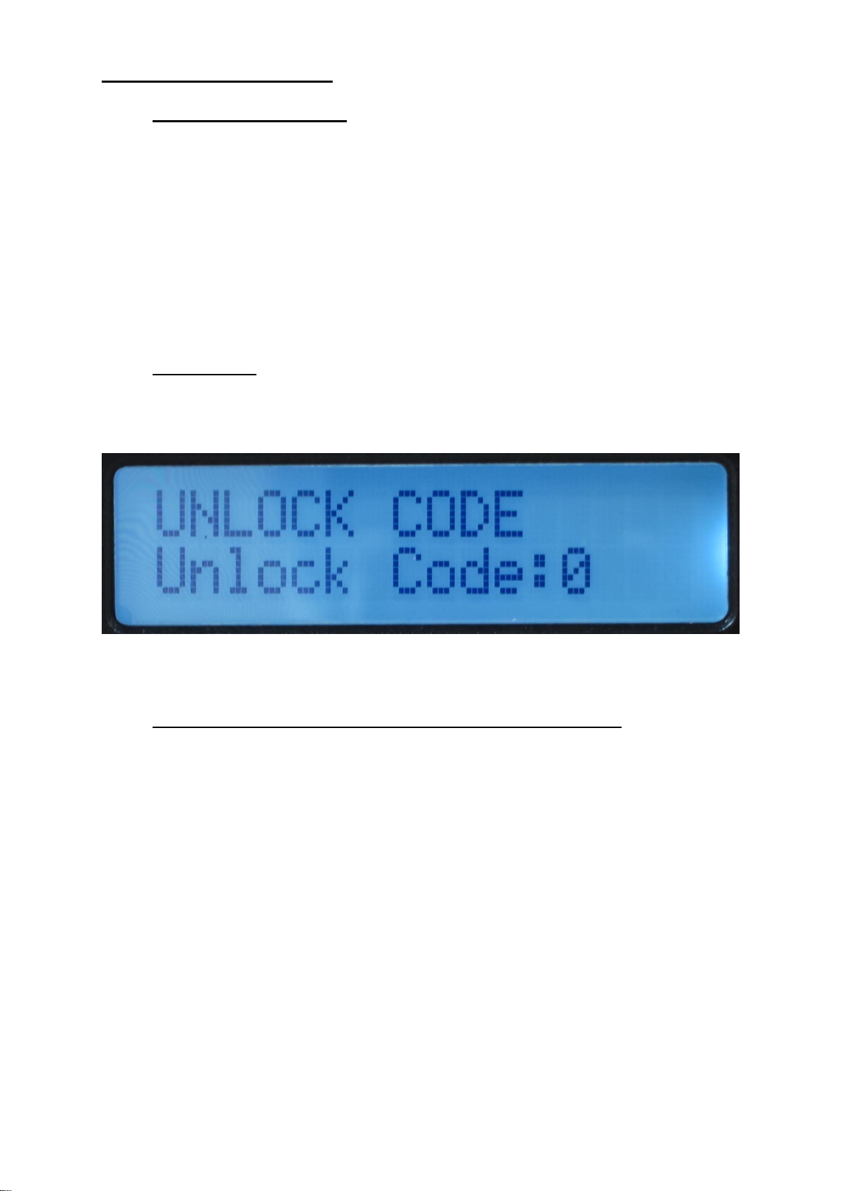
A. Unlock Code
To prevent operators entering the configuration menu and altering the device’s
settings when you first enter the setup mode the display asks for an unlock code.
To unlock the device rotate the Volume/ Setup knob until the number 45 is displayed
on the screen and then push the Volume/ Setup knob.
2. Selecting The Different Menus & Options Within The Menu
Once in setup mode with the device unlocked, rotate the Volume/ Setup knob to
scroll between the different menu settings. Once the display indicates the desired
menu that you would like to alter push the Volume/ Setup knob to enter that selected
sub menu.
Once in the sub menu, rotate the Volume/ Setup knob both clockwise and anticlockwise to display all available options for that parameter. When the setting that
you want to make is displayed on the screen push the Volume/ Setup knob and it will
then be set.
Page 17
Page 17 of 41
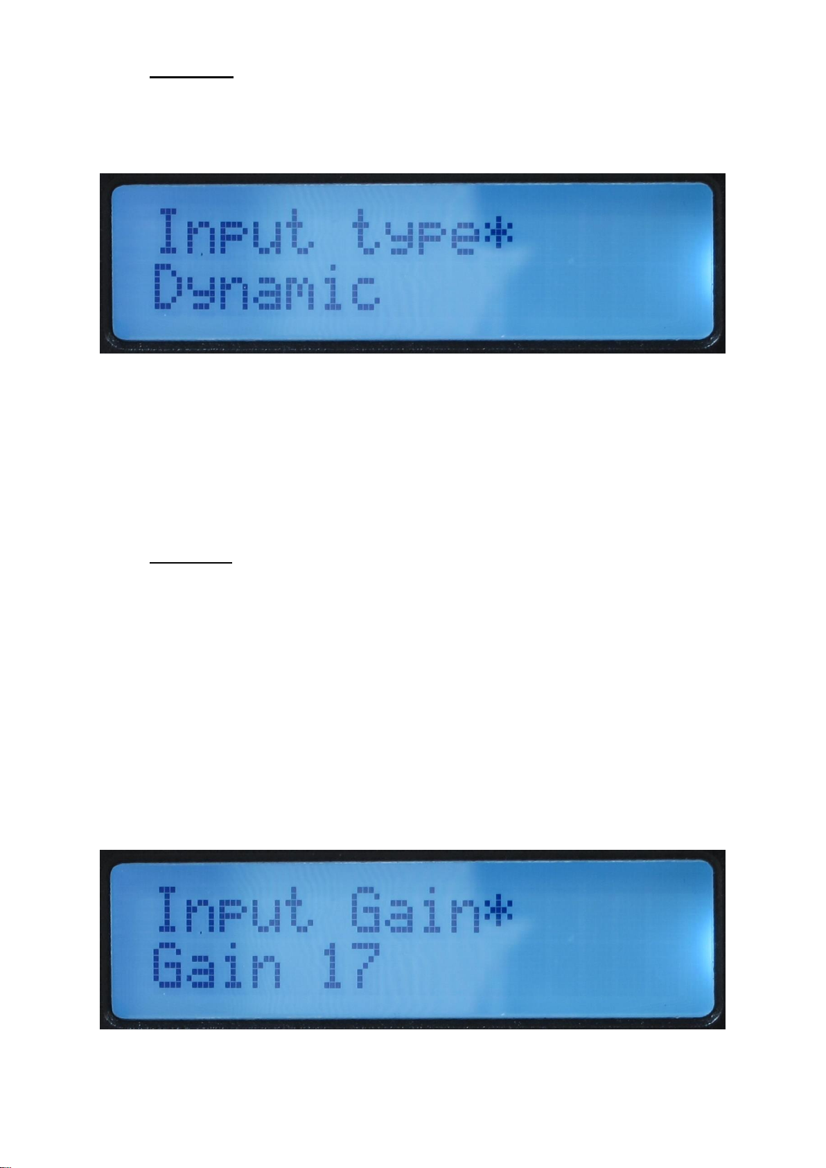
B. Input Type
This setting allows the user to select either the internal microphone or the external
microphone to be used for talkback purposes. There are 2 options for the external
microphone to allow different types of microphones to be connected.
AVAILABLE OPTIONS:
Dynamic: External mic input for dynamic microphones
Phantom: External mic input with +48V Phantom Power being supplied
Panel: The Internal microphone mounted behind the front panel. (Not available on
the Beltpack)
C. Input Gain
This adjusts the input gain of the microphone input and should be used to set the
output level of the user’s microphone to the intercom network.
The gain range is nominally marked 0 – 30 for panel mic and 0 – 17 for the external
mic.
To correctly set the gain, connect a microphone and set the appropriate input type,
enter the Input Gain menu and start talking into the microphone at the level that you
will use the unit. Next to the Gain level a very simple PPM will appear on the screen
made up of the characters >>>X<<< to indicate the audio level. The goal is to set the
level such that during normal speech the ‘X’ is on most the time and that you do not
get too many ‘<<’. If you don’t see the ‘X’ and only see ‘>>’ then you will need to turn
the gain up.
Page 18
Page 18 of 41
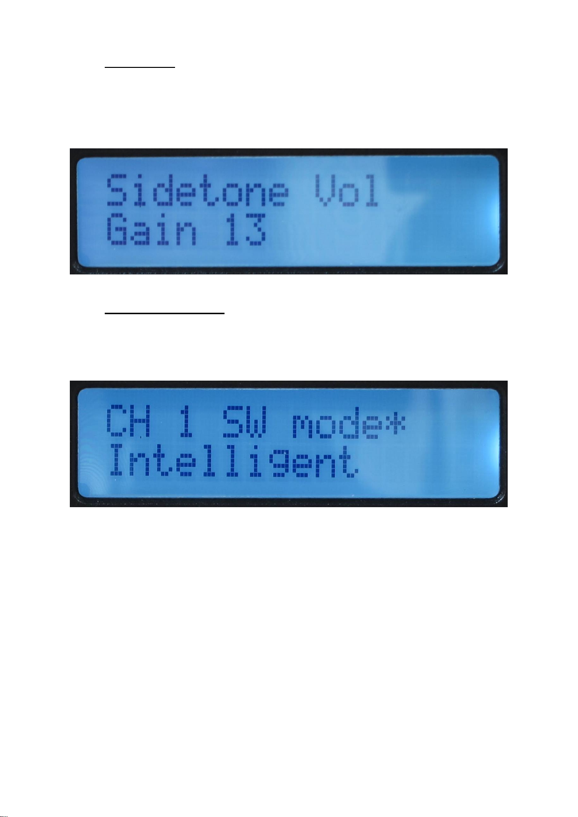
D. Sidetone Vol
Sidetone is standard terminology for the user’s own voice appearing the user’s own
headphones. It has no effect on the outgoing level heard by other people on the
intercom network.
This setting adjusts the gain (volume) of the user’s own voice in their heaphone feed.
E. CH1 to CH4 SW Mode
There are 4 identical menu options for setting the operation of the 4 talkback keys
(buttons/ switches). Each of the 4 talkback keys can be independantly set.
AVAILABLE OPTIONS:
Momentary: The talkback key must be held down to operate.
Latching: A push of the talkback key will turn the channel on, another push will then
turn the channel off.
Intelligent: A brief push of the talkback key will turn the channel on or off. But a
press and hold of the talkback key will only turn the output on (or off if already on)
while the key is being pressed.
Page 19
Page 19 of 41
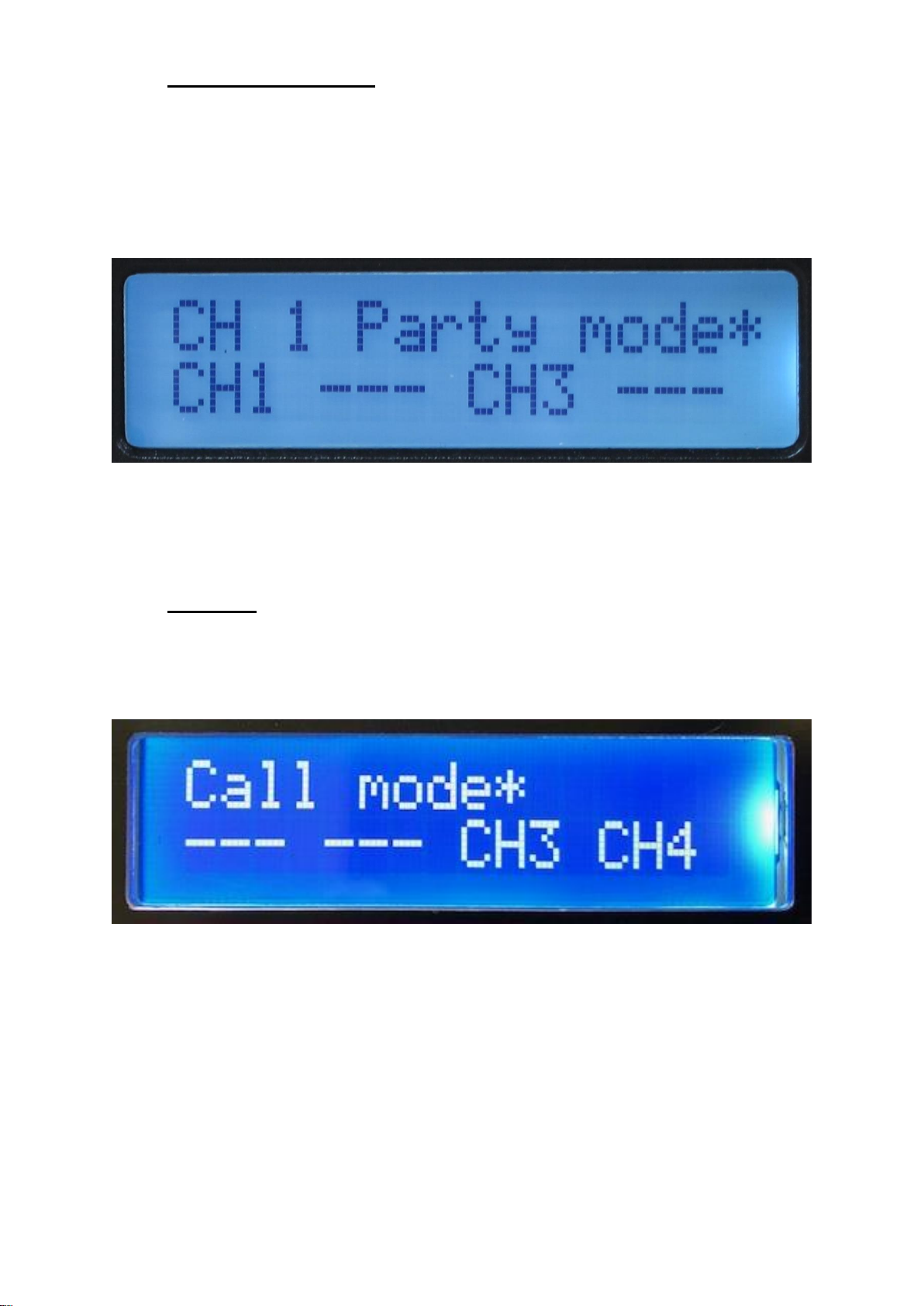
F. CH1 to CH4 Party Mode
There are 4 identical menu options to set part mode on the 4 output channels.
Party mode is a facility that can be used to set up a party line style intercom. When
in party mode the Channels output can have audio from any of the 4 incoming
circuits routed and mixed to it.
In the above screen shot, Channel 1’s output would have both Channel 1 and
Channel 3’s inputs routed to it. Therefore any incoming audio received on either
Channel 1 or 3 would also be received by the destination that Channel 1’s output is
routed to within the overall intercom system.
G. Call mode
This mode provides the ability to turn off the calling feature for any of the channels. If
you are in a setup where the calling feature is not being used, then turning it off
(disabling it) can prevent accidental triggering of the call circuit.
In the above screen shot only CH3 and CH4 have their call mode switched on.
Turning off the call mode turns off the transmitting of the call signal when a double
tap on the channels talk key is detected. It also turns of the detectors looking for an
incomming call signal.
Page 20
Page 20 of 41
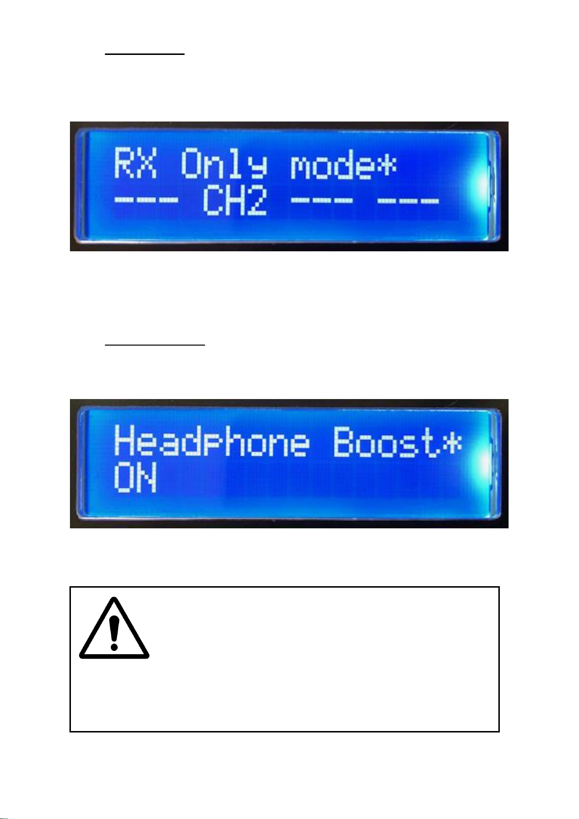
H. RX Only mode
The receive only mode allows one or more of the 4 circuits to be set to receive audio
only. When set in this mode pressing a channels talk key turns the associated
incoming audio circuit on/ off to the loudspeaker/ headphones.
When a channel is set to receive only the operators microphone is never routed to
the channels output and a call signal will also never be sent to the output.
In the above screenshot CH2 has been set to receive only.
I. Headphone Boost
Headphone boost is a facility provided in case you are working in a very noisy
enviroment. By turning it on the headphone output level is increased by 10dB.
If ‘ON’ is not shown on the setup screen as per the above picture then headphone
boost is turned off.
HIGH HEADPHONE LEVELS CAN BE DANGEROUS
Please note high headphone output levels can seriously damage you hearing. Please consult your
health and safety officer to confirm a suitable and safe output level prior to using this equipment.
Page 21
Page 21 of 41
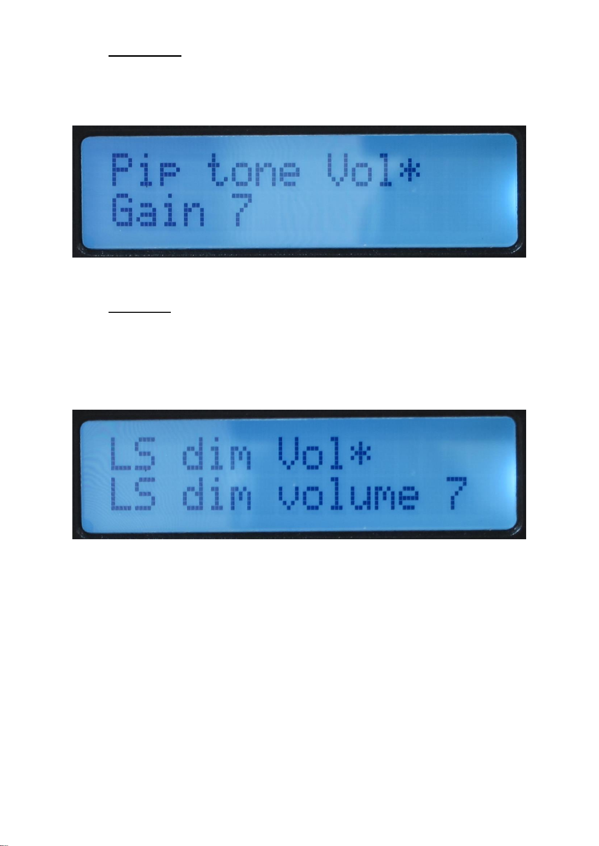
J. Pip Tone Vol
Pip tone is the audio alert that a call has been received on one of the channels and
is used to indicate to the user that there is an incomming call.
The volume of this alert can be adjusted using this control.
K. LS dim Vol
LS (Loudspeaker) dim, is the amount of dimming that occurs on the front panel
loudspeaker when a talkback key is pressed. By dimming the loudspeaker when a
talkback channel is on you reduce the amount of acoustical pickup between the
loudspeaker and microphone which helps to eliminate nasty acoustical feedback.
Note: LS Dim is not available on the beltpack B4.
Page 22
Page 22 of 41
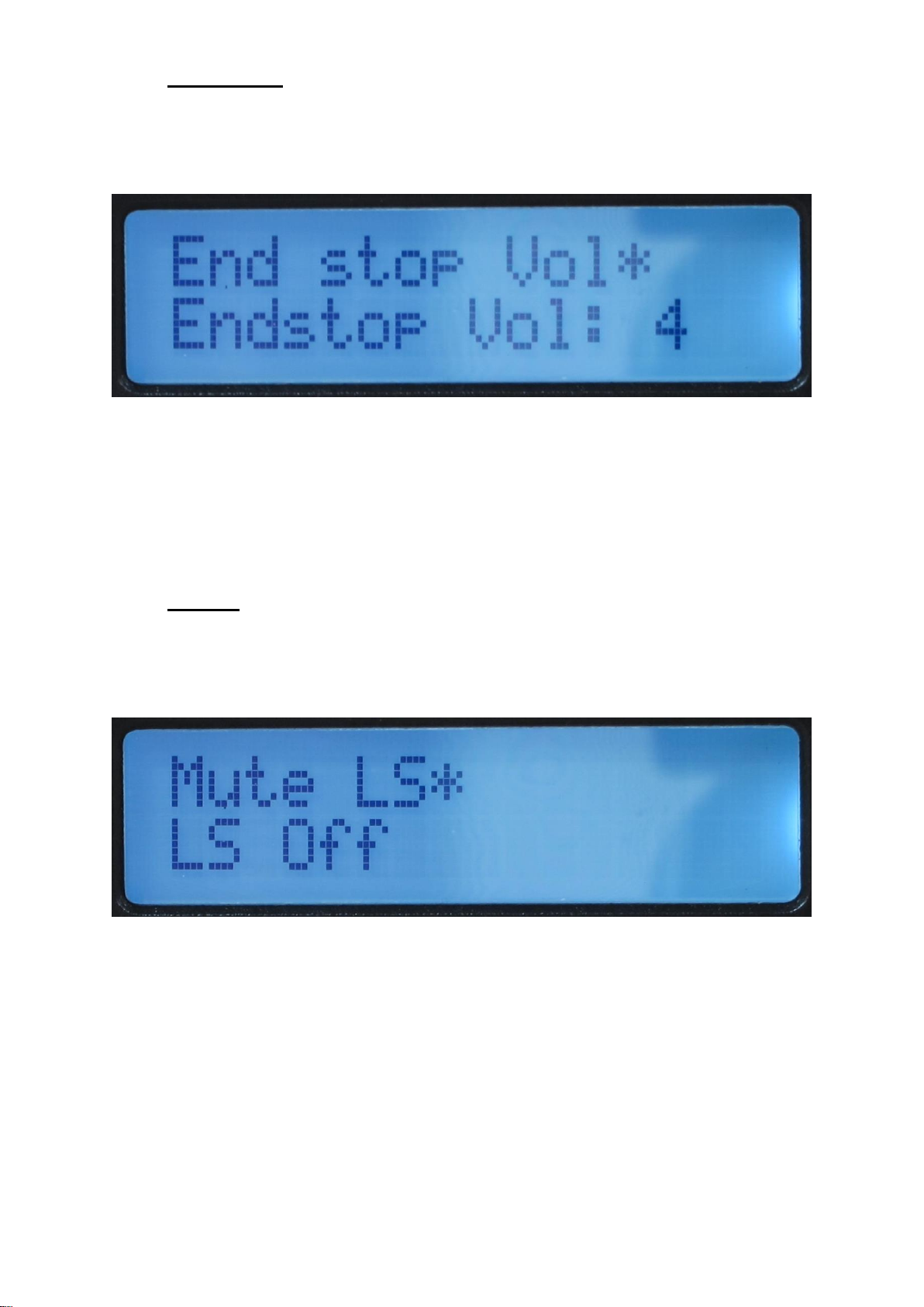
L. End Stop Vol
The term ‘End stop’ refers to old fashioned electronic volume circuits where an ‘end
stop’ resistor would be placed at the bottom of a volume potentiometer to prevent
that potentiometer from fully attenuating (turning off) the audio signal.
In the Beatrice units each of the 4 incoming audio circuits have their own adjustable
level control (to adjust the incoming level of one circuit, press the associated
talkback key and adjust the Volume/ setup knob).
This ‘End stop’ menu adjusts the minimum level that these 4 incoming audio circuits
can be set to, where ‘0’ equates to off and ‘10’ equates to full volume.
M. Mute LS
Mute LS, this control is either on or off. It turns the front panel loudspeaker on or off
and is normally used when the operator is wanting to operate from headset and
audio coming from the loudspeaker would disturb the local environment.
Note: LS Dim is not available on the beltpack B4.
Page 23
Page 23 of 41
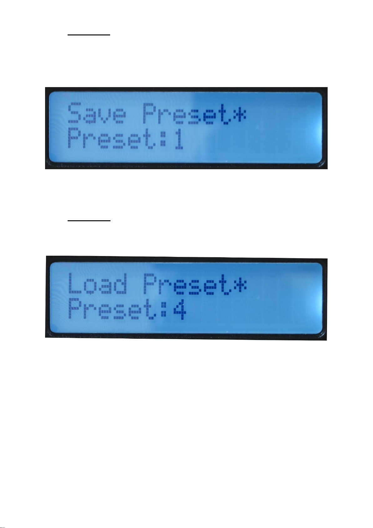
N. Save Preset
There are 4 presets available. If you select a preset (1 – 4) and push the volume/
setup knob then all the current settings will be saved to that position in non-volatile
memory. If there was a previously saved preset on the same preset number this will
be overwritten.
Please note the preset only saves configurations available via the menu system, it
does not save any Dante network information.
O. Load Preset
The load preset menu recalls previously saved configurations.
Page 24

Page 24 of 41
P. Factory Reset
If the factory reset menu is entered and ‘Yes’ selected (and then the Volume/ Setup
knob is pushed) then the units configuration will return to factory defaults.
Please note factory reset will not overwrite and saved presets.
Page 25

Page 25 of 41
FACTORY PRESETS
If the factory reset menu option is sleected the device will return to the following
parameters.
Please note that any saved presets are not affected by the factory reset operation.
hp_mix.rx1_gain = 15;
hp_mix.rx2_gain = 15;
hp_mix.rx3_gain = 15;
hp_mix.rx4_gain = 15;
hp_mix.rx1_pan = 7;
hp_mix.rx2_pan = 7;
hp_mix.rx3_pan = 7;
hp_mix.rx4_pan = 7;
hp_mix.sidetone_level = 7;
hp_mix.sidetone_pan = 7;
tx_channel_mix[0].button_mode = 2; //intelligent
tx_channel_mix[1].button_mode = 2;
tx_channel_mix[2].button_mode = 2;
tx_channel_mix[3].button_mode = 2;
tx_channel_mix[0].party_mode = 0;
tx_channel_mix[1].party_mode = 0;
tx_channel_mix[2].party_mode = 0;
tx_channel_mix[3].party_mode = 0;
hp_mix.pip_gain = 7;
hp_mix.master_gain = 15;
hp_mix.ls_dim_gain = 0;
hp_mix.rx_endstop_gain = 6;
ls_mix.ls_mute = 0;
mic_line.current_input_type = 0; //dynamic
mic_line.current_input_gain = 10;
mic_line.current_pwr_state = 0;
mic_line.phantom_gain = 10;
mic_line.dynamic_gain = 10;
mic_line.panel_mic_gain = 15;
Page 26
Page 26 of 41
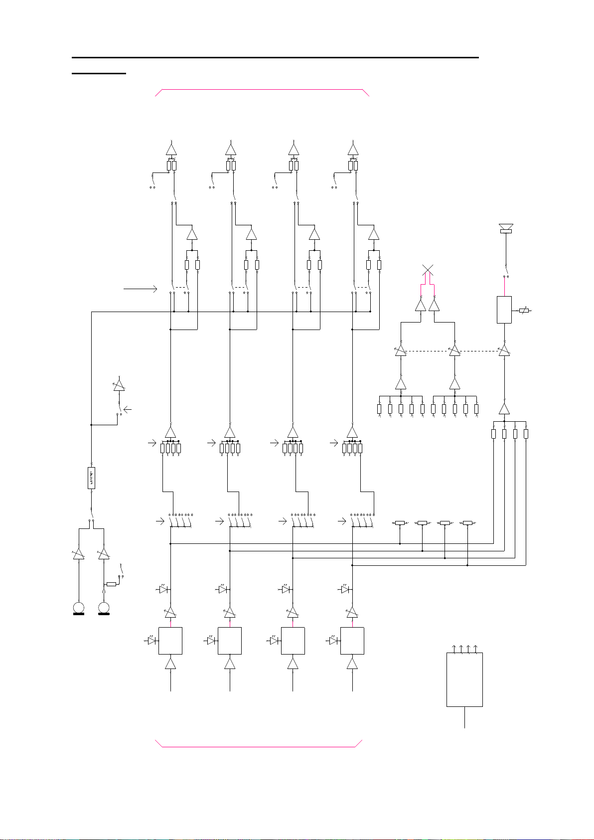
AUDIO BLOCK DIAGRAMS (analogue representation of digtal circuits)
DIM
PANEL MIC
XLR MIC
INPUT 1
SPEAK TB DIM/ CUT
OUTPUT 1
SET DIM LEVEL
PSU
+12V
+3.3V0V-12V
100 - 250 VAC
DETECT
I/P GAIN
(INTERNAL)
SPEAK SWITCHES HAVE INTERNAL LED
ILLUMINATION TO INDICATE STATE
HEADPHONES/ LS VOLUME
INTERNAL LS
AUDIO TO DANTE NETWORK
TO CH 2 IFB MIX
FROM CH 2 IFB MATRIX SWITCH
TO CH 3 IFB MIX
FROM CH 3 IFB MATRIX SWITCH
TO CH 4 IFB MIX
FROM CH 4 IFB MATRIX SWITCH
IFB MATRIX
SWITCHES
IFB MATRIX
MIXERS
PRESENCE
DETECT
CALL
CALL
DETECT
FILTER
CALL
INPUT 2
SPEAK TB DIM/ CUT
OUTPUT 2
DETECT
I/P GAIN
TO CH 1 IFB MIX
FROM CH 1 IFB MATRIX SWITCH
TO CH 3 IFB MIX
FROM CH 3 IFB MATRIX SWITCH
TO CH 4 IFB MIX
FROM CH 4 IFB MATRIX SWITCH
IFB MATRIX
SWITCHES
IFB MATRIX
MIXERS
PRESENCE
DETECT
CALL
CALL
DETECT
FILTER
CALL
INPUT 3
SPEAK TB DIM/ CUT
OUTPUT 3
DETECT
I/P GAIN
TO CH 2 IFB MIX
FROM CH 2 IFB MATRIX SWITCH
TO CH 1 IFB MIX
FROM CH 1 IFB MATRIX SWITCH
TO CH 4 IFB MIX
FROM CH 4 IFB MATRIX SWITCH
IFB MATRIX
SWITCHES
IFB MATRIX
MIXERS
PRESENCE
DETECT
CALL
CALL
DETECT
FILTER
CALL
INPUT 4
SPEAK TB DIM/ CUT
OUTPUT 4
DETECT
I/P GAIN
TO CH 2 IFB MIX
FROM CH 2 IFB MATRIX SWITCH
TO CH 3 IFB MIX
FROM CH 3 IFB MATRIX SWITCH
TO CH 1 IFB MIX
FROM CH 1 IFB MATRIX SWITCH
IFB MATRIX
SWITCHES
IFB MATRIX
MIXERS
PRESENCE
DETECT
CALL
CALL
DETECT
FILTER
CALL
TO LEFT EAR MIX
TO RIGHT EAR MIX
TO LEFT EAR MIX
TO RIGHT EAR MIX
TO LEFT EAR MIX
TO RIGHT EAR MIX
TO LEFT EAR MIX
TO RIGHT EAR MIX
FROM INPUT 1 LEFT EAR MIX
FROM INPUT 2 LEFT EAR MIX
FROM INPUT 3 LEFT EAR MIX
FROM INPUT 4 LEFT EAR MIX
FROM INPUT 1 RIGHT EAR MIX
FROM INPUT 2 RIGHT EAR MIX
FROM INPUT 3 RIGHT EAR MIX
FROM INPUT 4 RIGHT EAR MIX
LEVEL
SIDETONE
SWITCH MADE WHEN ANY OF
SPEAK KEYS ARE ON
SIDETONE TO HEADPHONES
SIDETONE
SIDETONE
CUT LS
UNIT WILL ALSO POWER FREOM PoE
+48V Phantom
Page 27
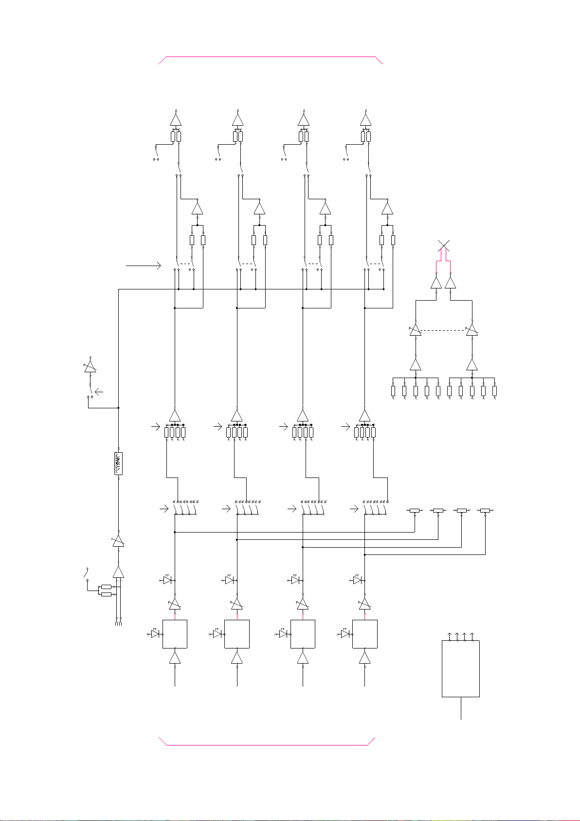
Page 27 of 41
INPUT 1
SPEAK TB DIM / CUT
OUTPUT 1
PSU
+12V
+3.3V0V-12V
PoE
DETECT
I/P GAIN
SPEAK SWITCHES HAVE INTERNAL LED
ILLUMINATION TO INDICATE STATE
HEADPHONES/ LS VOLUME
AUDIO TO DANTE NETWORK
TO CH 2 IFB MIX
FROM CH 2 IFB MATRIX SWITCH
TO CH 3 IFB MIX
FROM CH 3 IFB MATRIX SWITCH
TO CH 4 IFB MIX
FROM CH 4 IFB MATRIX SWITCH
IFB MATRIX
SWITCHES
IFB MATRIX
MIXERS
PRESENCE
DETECT
CALL
CALL
DETECT
FILTER
CALL
INPUT 2
SPEAK TB DIM / CUT
OUTPUT 2
DETECT
I/P GAIN
TO CH 1 IFB MIX
FROM CH 1 IFB MATRIX SWITCH
TO CH 3 IFB MIX
FROM CH 3 IFB MATRIX SWITCH
TO CH 4 IFB MIX
FROM CH 4 IFB MATRIX SWITCH
IFB MATRIX
SWITCHES
IFB MATRIX
MIXERS
PRESENCE
DETECT
CALL
CALL
DETECT
FILTER
CALL
INPUT 3
SPEAK TB DIM / CUT
OUTPUT 3
DETECT
I/P GAIN
TO CH 2 IFB MIX
FROM CH 2 IFB MATRIX SWITCH
TO CH 1 IFB MIX
FROM CH 1 IFB MATRIX SWITCH
TO CH 4 IFB MIX
FROM CH 4 IFB MATRIX SWITCH
IFB MATRIX
SWITCHES
IFB MATRIX
MIXERS
PRESENCE
DETECT
CALL
CALL
DETECT
FILTER
CALL
INPUT 4
SPEAK TB DIM / CUT
OUTPUT 4
DETECT
I/P GAIN
TO CH 2 IFB MIX
FROM CH 2 IFB MATRIX SWITCH
TO CH 3 IFB MIX
FROM CH 3 IFB MATRIX SWITCH
TO CH 1 IFB MIX
FROM CH 1 IFB MATRIX SWITCH
IFB MATRIX
SWITCHES
IFB MATRIX
MIXERS
PRESENCE
DETECT
CALL
CALL
DETECT
FILTER
CALL
TO LEFT EAR MIX
TO RIGHT EAR MIX
TO LEFT EAR MIX
TO RIGHT EAR MIX
TO LEFT EAR MIX
TO RIGHT EAR MIX
TO LEFT EAR MIX
TO RIGHT EAR MIX
FROM INPUT 1 LEFT EAR MIX
FROM INPUT 2 LEFT EAR MIX
FROM INPUT 3 LEFT EAR MIX
FROM INPUT 4 LEFT EAR MIX
FROM INPUT 1 RIGHT EAR MIX
FROM INPUT 2 RIGHT EAR MIX
FROM INPUT 3 RIGHT EAR MIX
FROM INPUT 4 RIGHT EAR MIX
LEVEL
SIDETONE
SWITCH MADE WHEN ANY OF
SPEAK KEYS ARE ON
SIDETONE TO HEADPHONES
SIDETONE
SIDETONE
HEADPHONES
+48V
Mic In
Page 28

Page 28 of 41
CONNECTING THE BEATRICE UNITS TO A DANTE NETWORK
The Beatrices are network audio devices utilizing the reliable and versatile Dante
audio over IP protocol. Dante is a proprietary system (although very widely used) the
originators of which are Audinate.
The information below is only meant as a very basic guide. Full details of the power
of Dante network audio and instructions for using it can be found at
www.audinate.com
Getting Dante Controller
If you are connecting the Beatrice to a new Dante network the first thing you will
need to do is to get the free Dante controller software from Audinate.
This can be downloaded by visiting Audinate’s web site at www.audinate.com
Connecting Beatrice To The Network
Beatrices can be connected to the network that you are going to use for your audio
distribution simply by plugging in either, and, or any of the network connections on
the rear. Once connected to the network it will be possible to see the inferno from
within the Dante controller and route its’ audio circuits.
Audio Over IP Network
We strongly recommend that you consider your network topology carefully and
would not recommend sharing broadcast audio and general data on the same
network.
For more details of audio over IP network structure please visit www.audinate.com
Page 29
Page 29 of 41
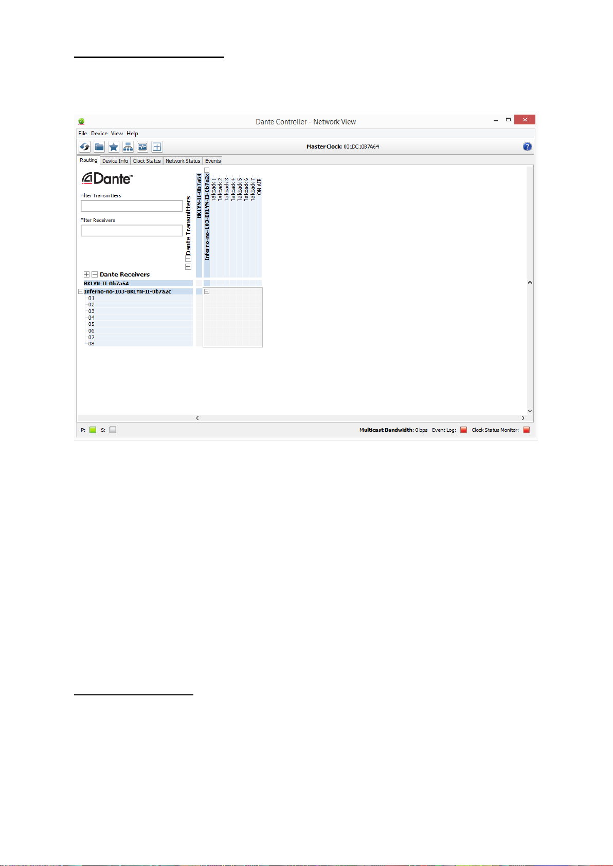
Running Dante Controller
At the time of writing this manual the Dante Controller looks as per the screenshot
below:
The Beatrice will have been named at the factory during test to allow them to be
identified by the Dante controller.
The format used for the factory name is:
‘BeatriceXX-snXXX’
Where ‘BeatriceXX’ refers to the Glensound product i.e. BeatriceR4 or D4 or B4.
The ‘–snXXX’ refers to the serial number of the Beatrice unit which can be found
printed on the rear or side of the unit.
Note if you upload a new DNT file or clear the devices config then the name will
change to BeatriceXX-xxXxXx whereby the ‘X’s refer to the devices MAC address.
Dante Controller TIP
If you have never run Dante controller before then make sure that on the bottom left
of the Dante controllers’ screen ‘P’ or ‘S’ is next to a green square as this indicates
that it is connected to a network. By clicking ‘P’ or ‘S’ a pop up box opens to allow
you to set what network interface the controller is using.
Page 30
Page 30 of 41
Device Not Showing Up In Dante Controller
If your DanteTM device does not show up in DanteTM Controller then the most likely
issue is that the device’s IP Address is not appropriate for your network.
A) It maybe that the device is set to obtain an IP address automatically using
DHCP (this is the default configuration) and your network is setup for fixed IP
addresses only and does not have a DHCP server.
B) It maybe that the device has had a fixed IP address assigned but that this
address is not suitable for your network.
The solution to both scenarios is basically the same.
1) You must connect your DanteTM device directly to the Ethernet port of your
computer using an Ethernet cable.
2) Make sure that your computer is set to ‘Obtain an IP address automatically’
3) After a few minutes the DanteTM device should now appear in DanteTM
Controller.
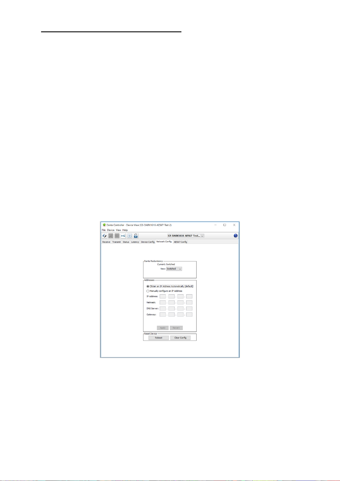
4) Double click the device name to open up device view.
5) Open up the ‘Network Config’ tab
6) Either turn on ‘Obtain an IP Address Automatically’ or correctly configure the
‘Manually configure an IP Address’ options for your network.
7) Click on ‘Apply’ to confirm the new settings, then disconnect the computer and
reconnect the DanteTM device to your network.
Page 31
Page 31 of 41
AES67 MODE
The Beatrice uses a chipset from Audinate called Ultimo for its network audio
interface. Audinate are the company behind DanteTM and as such the chipset’s
primary network audio protocol is Dante, however Audinate have enabled their
module to comply with AES67 and therefore the Beatrice can be set to AES67 mode
for interaction with other AES67 devices.
Please note however that Glensound are relying on Audinate’s AES67 interface and
are unfortunately not able to provide full AES67 support for the unit. AES67 support
should be sought directly from Audinate.
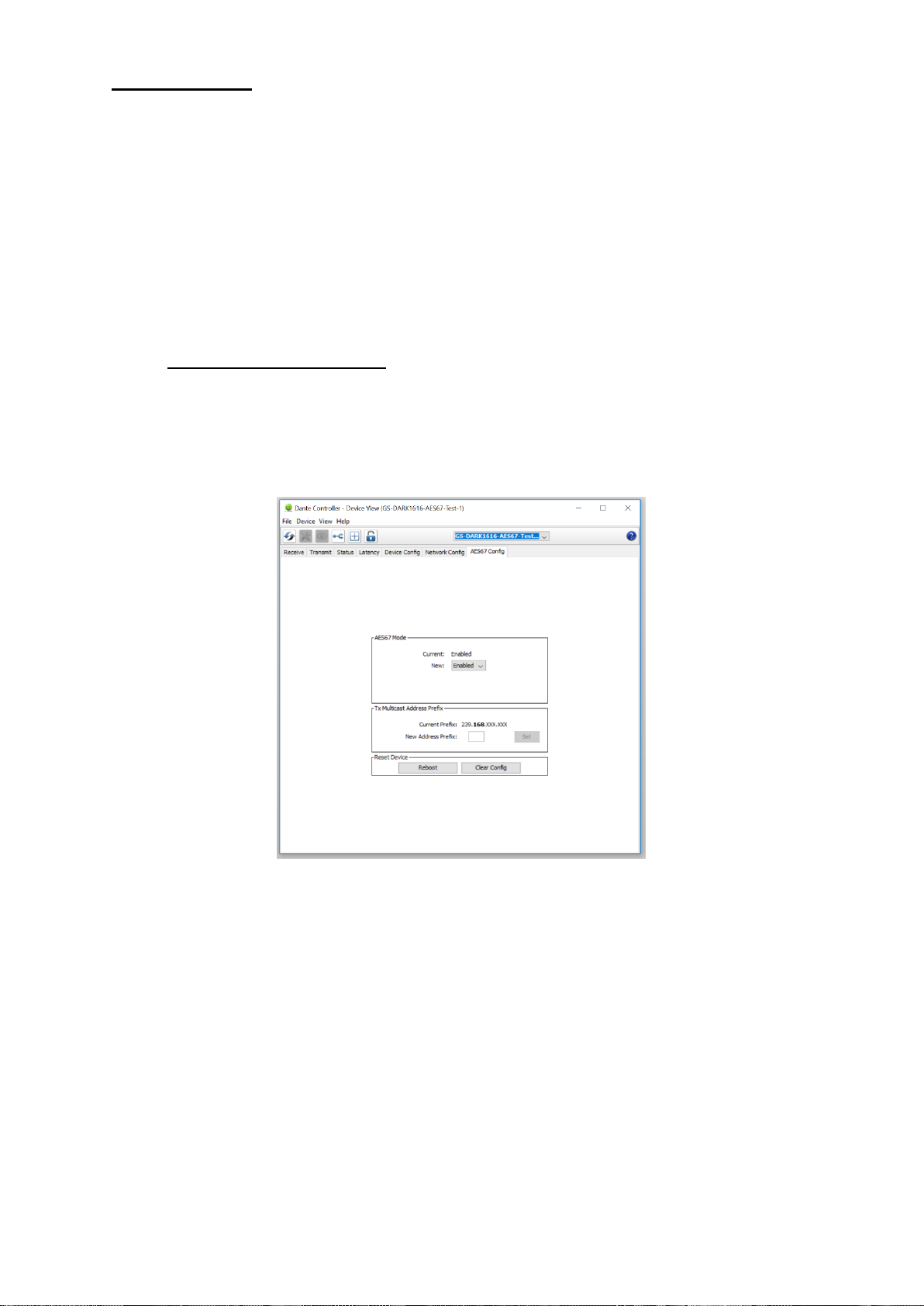
1. Turning On AES67 Mode
If you want to use your Beatrice on an AES67 network and it has not been set to
AES67 mode then this can be set in Dante controller by double clicking the Beatrice
to open the Device View window where you will find an AES67 tab to enable AES67
support.
Once the AES67 drop down box has been enabled you’ll have to reboot the Beatrice
for the change to take effect. After the reboot go back to the AES67 tab and set the
multicast prefix address to one that is suitable for your newtork.
Page 32
Page 32 of 41
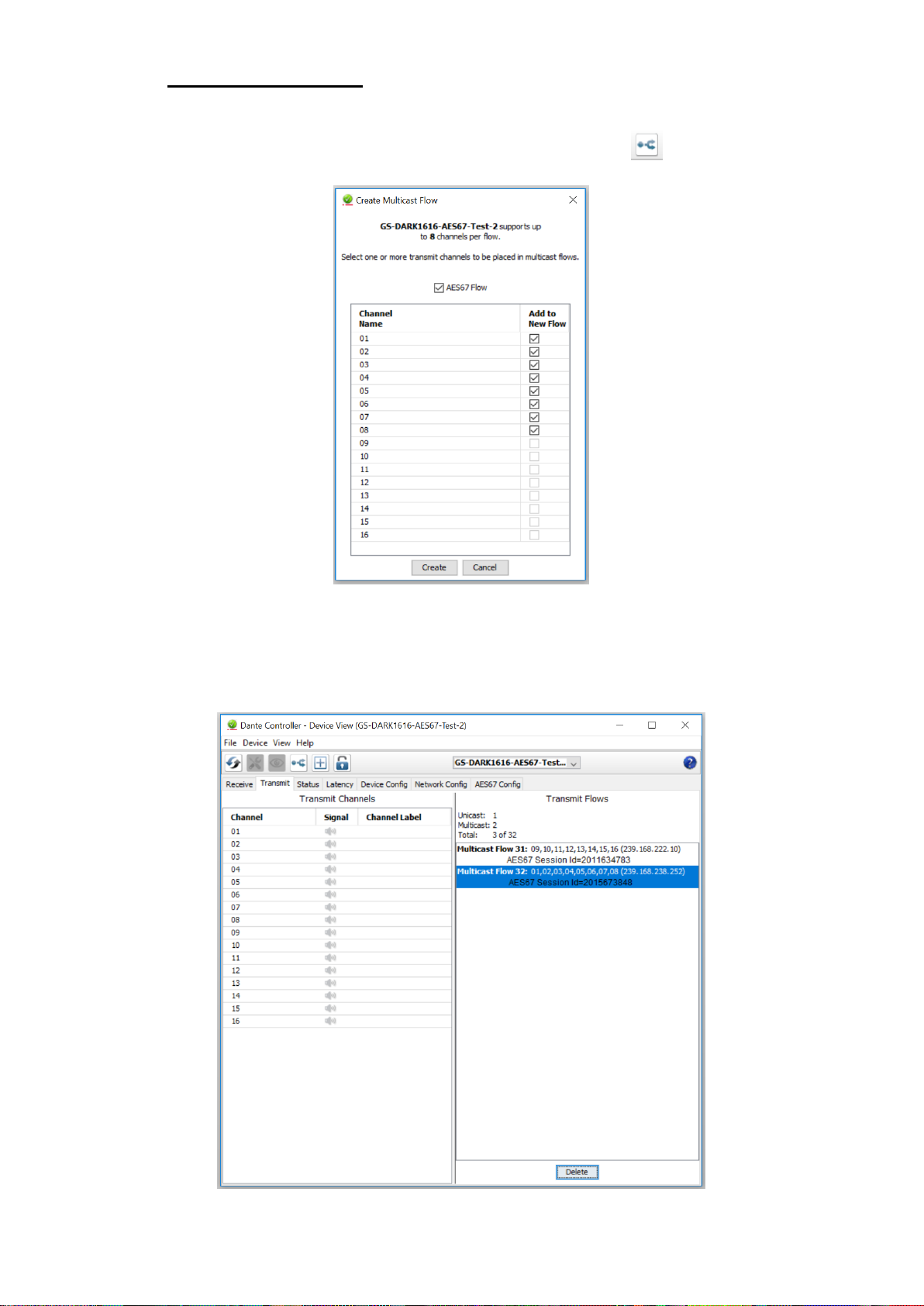
2. Sending AES67 Audio
To transmit AES67 audio to the network a multicast flow must first be setup.
This is done by selecting the ‘Create New Multicast Flow’ Icon in the Device
View.
Tick the AES67 Flow check box, then select up to 4 channels to be included in the
flow then click ‘Create’
Once set the flows can be seen in the transmit tab of the device view.
Page 33

Page 33 of 41
3. Receiving AES67 Audio
Once a compatible AES67 stream is detected on the network by Dante Controller the
AES67 flows will appear in the Dante Transmitters section in the Routing tab.
4. AES67 Restrictions
AES67 flows can only be generated with the following constraints:
• Multicast Only
• Non-redundant
• Destination address in range 239.nnn.0.0 to 239.nnn.255.255 (239.nnn/16),
port 5004
• 48kHz sampling rate
• 24 bit linear (L24) encoding
• 1 msec packet time
• Up to 8 channels per stream
Received AES67 flows have the following constraints:
• Multicast Only
• Non-redundant
• Destination address in range 239.nnn.0.0 to 239.nnn.255.255 (239.nnn/16),
port 5004. Must match destinatio address range.
• 48kHz sampling rate
• L16 or L24 encoding
• 125usec, 250usec, 333usec, 1 msec packet time
• Up to 8 channels per stream
Page 34
Page 34 of 41
UPDATING FIRMWARE
The Beatrice units are a digital audio system comprising of a Micro Controller and
ADC and DAC converters. These items run software and may need to be
occasionally updated.
Equipment needed
• A windows based PC
• USB Type A to Micro B cable
• A copy of ‘DfuSe Demo’ software
• The latest firmware from Glensound
• The Beatrice unit to update
Instructions
1. Download and install DfuSE Demo
‘DfuSE Demo’ is a firmware updating tool that is required for loading new
firmware on to the Beatrice.
It can be downloaded from the STMicroelectronics website found here:
https://goo.gl/AbzhsA. It is the file named “STSW-STM32080”.
Once you have downloaded this file you will need to extract the .exe
“DfuSe_Demo_V3.0.5_Setup.exe”, then run and install it.
2. Download firmware
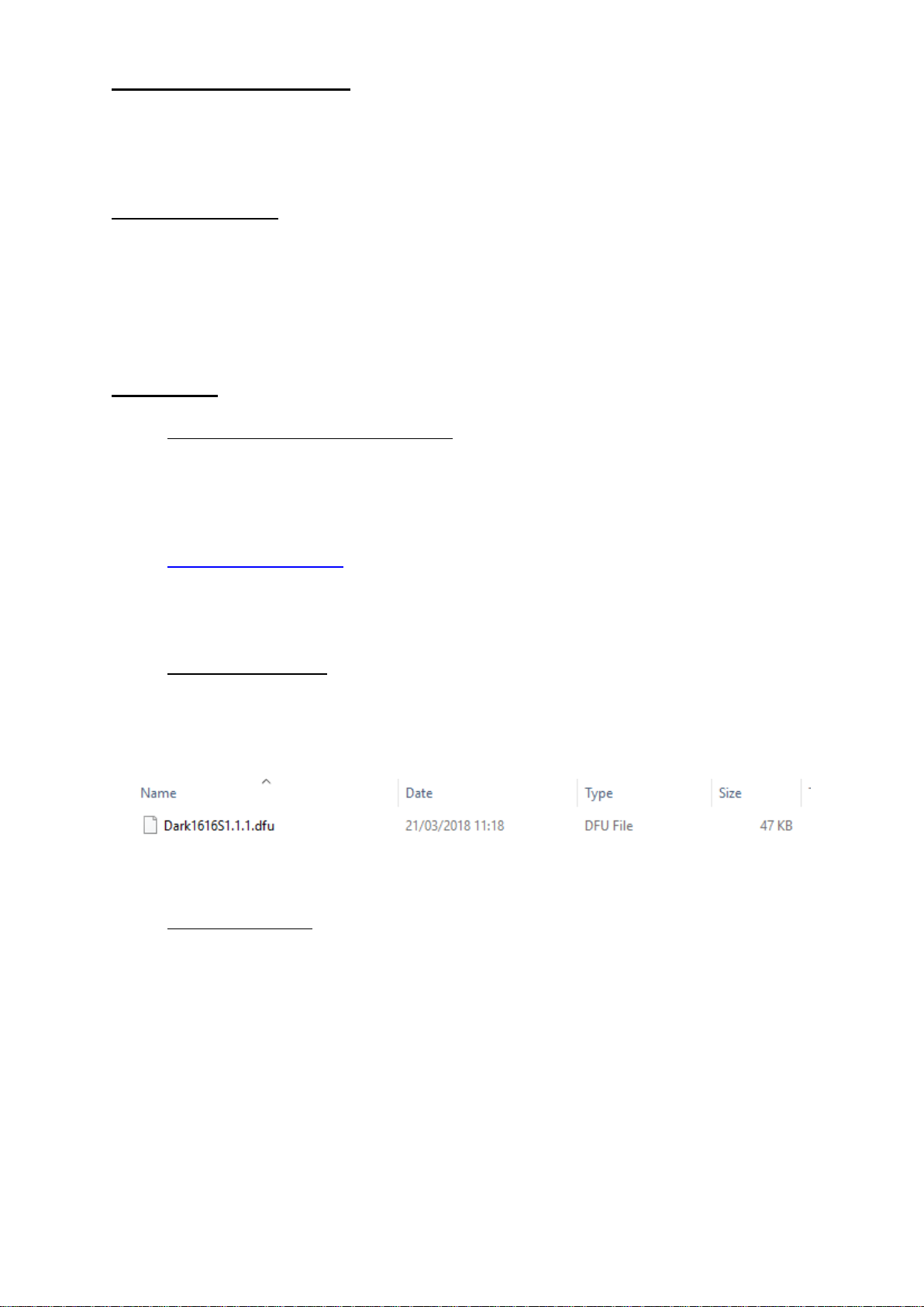
The latest firmware for the Beatrice can be found on the Glensound website,
under the product page for Beatrice device. Once you have downloaded the
file, place it in a folder or location of your choice.
3. Connect To A PC
Connect the Beatrice to the PC via the USB cable. The Micro USB connector
is located on the rear panel of the unit.
Figure 1 Example filename
Page 35
Page 35 of 41
4. Firmware update preperation
To prepare the Beatrice for a firmware update;
1. Press and hold down the Enter Setup button
2. Power on the unit
3. Release the Enter Setup button
Your PC should make an audible sound when this process is successful as
windows is detecting a new USB device.
5. Loading the firmware
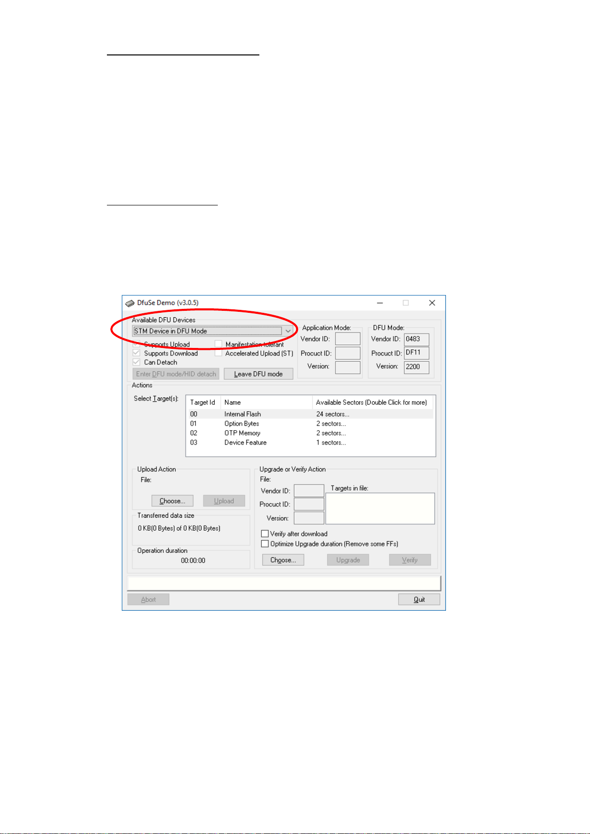
Now open DfuSe Demo.
If the Beatrice successfully entered DFU mode then it will appear as ‘STM
Device in DFU Mode’ under the ‘Available DFU Devices tab’.
Now the .dfu file needs to be selected so that DfuSe Demo knows the correct
firmware to put on to the Beatrice.
Figure 2 Device successfully recognised
Page 36
Page 36 of 41
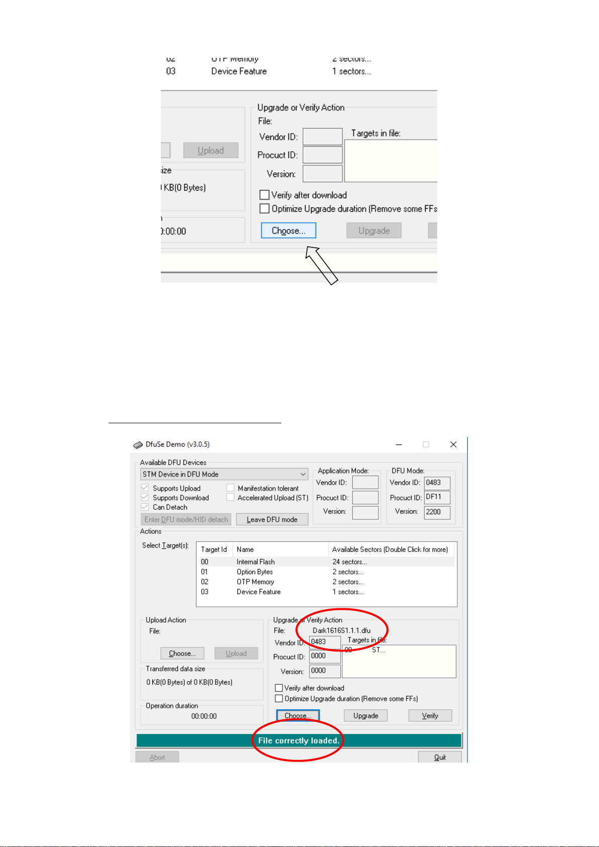
Click choose and then select the .dfu file that you downloaded from the
Glensound website. This will be located in your downloads folder by default.
If the file loads successfully then it will read along the bottom ‘File correctly
loaded’.
6. Upgrading the Beatrice firmware
Figure 3 Choose .dfu file
Figure 4 .dfu successfully loaded
Page 37
Page 37 of 41
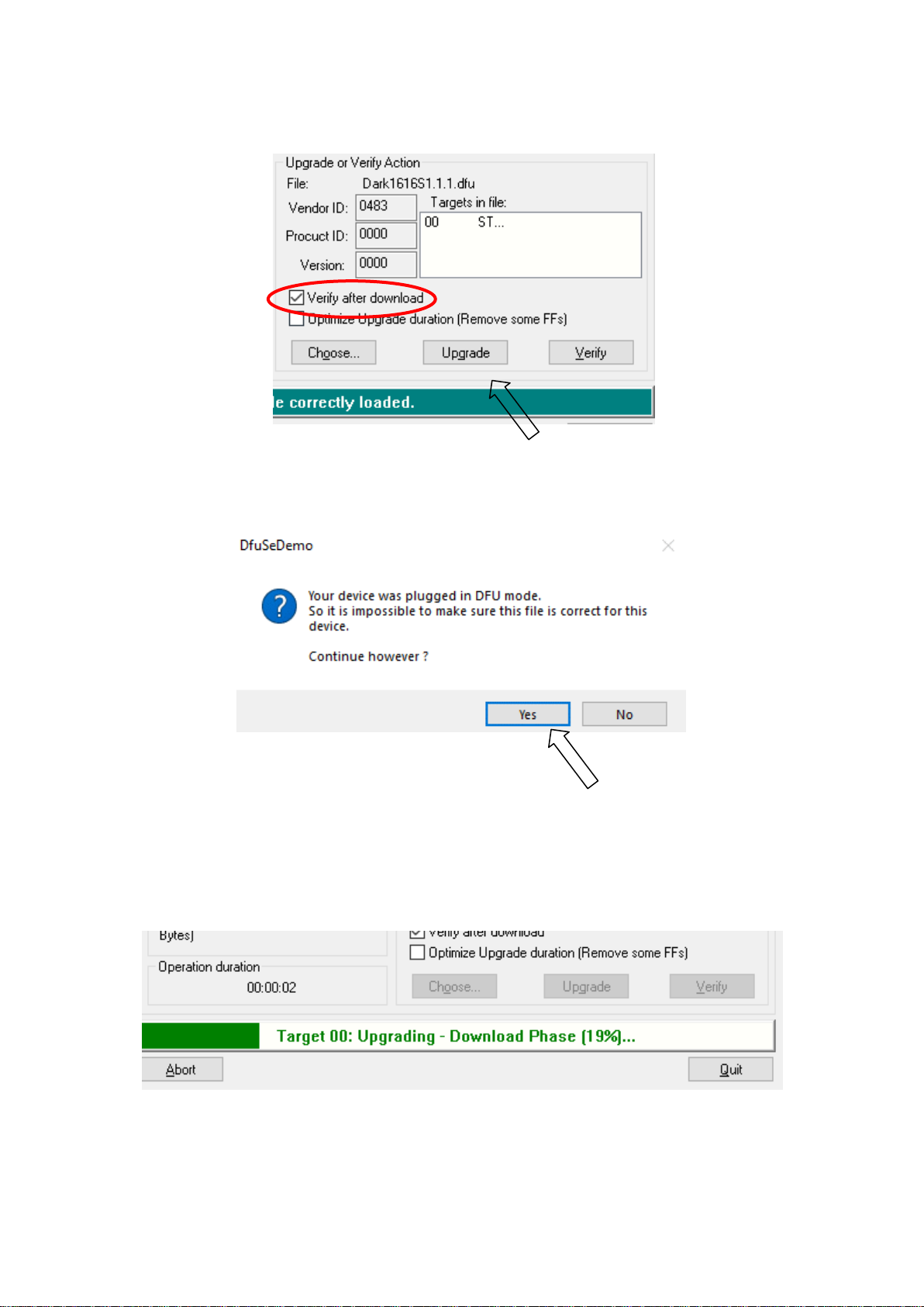
The firmware is now ready to be put on to the Beatrice. Tick the ‘Verify after
download’ box first and then click ‘Upgrade’.
Click yes to proceed.
The progress bar along the bottom will show the status of the operation.If the
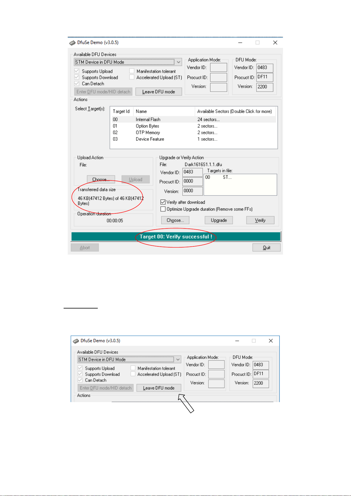
operation was successful, DfuSe Demo will report that “Target 00: Verify
Successful!”.
You may also see that it will report how much data was successfully transferred.
Figure 5 Upgrade
Figure 6 Start upgrade
Figure 7 Upgrade status
Page 38
Page 38 of 41
7. Final steps
Now click “Leave DFU mode” to finish the procedure.
You may now disconnect the USB cable and continue to use the Beatrice with
the freshly updated firmware!
Figure 8 Successful upgrade!
Figure 9 Final step
Page 39

Page 39 of 41
UPDATING THE ULTIMO CHIPSET
The Ultimo Chipset is a device supplied by Audinate that does most of the
processing for the actual Dante/ AES67 network audio streams. There is one Ultimo
Chipset in each Beatrice. We supply special code (a .dnt file) that sets up/ initiates
the Ultimo Chipset and makes it work in particular way that is compatible to the
Beatrice.
1. Finding Out Current Installed Version
Using Dante® controller double click on the Beatrice device name in the routing tab
to open the Device View box.
In the Device View box open the Status Tab.
The ‘Product Version:’ shows the currently installed version of Ultimo Chipset dnt
code.
2. Finding Out What The Latest Available Version Is
Go the Beatrice’s web and open the ‘Firmware Latest Version’ Tab.
This will give both the latest version numbers/ file names and also the location to
download the file from.
3. Updating the Ultimo Chipset
The firmware that runs in the Ultimo Chipset is updated using Audinate’s Firmware
updating tool. The updating tool and a user guide can be downloaded from
Audinate’s website:
https://www.audinate.com/products/firmware-update-manager
NOTE:
Please note we strongly advise that when you do the update that only your PC and
the Paradiso that you want to update are on the network to save accidently updating
the wrong Dante device.
Page 40
Page 40 of 41
WIRING INFORMATION
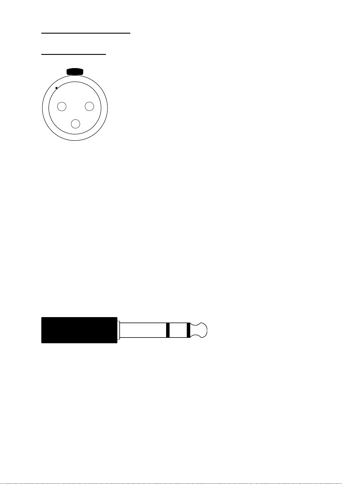
XLR & JACK Wiring
12
3
XLR SOCKET (FEMALE)
TIP
RING
SLEEVE
STANDARD XLR AUDIO PINOUTS:
1: Ground/ Earth
2: INPHASE/ POSITIVE/ MIC +
3: MATE/ NEGATIVE/ MIC -
STANDARD HEADPHONE WIRING:
TIP: A/ LEFT Ear
RING: B/ RIGHT Ear
SLEEVE: Common/ Earth
Page 41

Page 41 of 41
OPTIONAL 5 or 4 PIN XLR WIRING INFORMATION
5 PIN XLR AUDIO PINOUTS:
Female XLR fitted to Beatrice, mates
with cable mounted male
1: MATE/ NEGATIVE/ MIC 2: INPHASE/ POSITIVE/ MIC +
3: GROUND/ EARTH
4: HEADPHONE LEFT
5: HEADPHONE RIGHT
4 PIN XLR AUDIO PINOUTS:
Male XLR fitted to Beatrice, mates with
cable mounted female
1: MIC GND/ MIC –
2: INPHASE/ POSITIVE/ MIC +
3: HEADPHONE GND
4: POSITIVE/ HEADPHONE +
1 2 3 4 5 1 2
3
4
 Loading...