

Page 1

AoIP44
Analogue Audio To Dante Interface
4 analogue audio inputs & outputs to Dante network
audio
User Guide
Glensound
6 Brooks Place, Maidstone
Kent, UK, ME14 1HE
Tel: +44 (0)1622 753662
www.glensound.co.uk
Page 2

Glensound Electronics Ltd
Thank you for choosing a new Glensound product.
All rights reserved.
Information contained in this manual is subject to change without notice, if in
doubt please contact us for the latest product information.
If you need any help with the product then we can be contacted at:
Glensound Electronics Ltd
1 – 6 Brooks Place
Maidstone
Kent
ME14 1HE
United Kingdom
Telephone: +44 (0) 1622 753662
Fax: +44 (0) 1622 762330
EMAIL ADDRESSES
General enquires: [email protected]
Technical enquires: [email protected]
Sales enquires: [email protected]
Page 2 of 20
Page 3
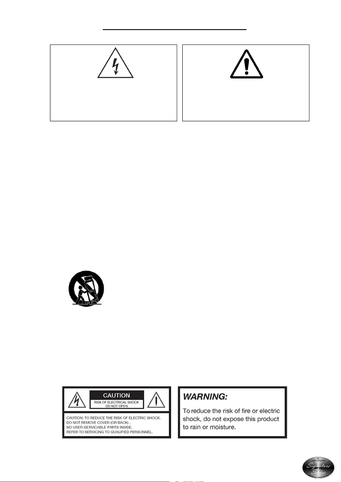
IMPORTANT SAFETY INSTRUCTIONS
shock.
This symbol is intended to warn that
dangerous voltages within the product are
present and constitute a risk of electric
1) Read these instructions
2) Keep these instructions
3) Heed all warnings
4) Follow all instructions
5) Do not use this apparatus near water
6) Clean only with a dry cloth
7) Do not block any ventilation openings. Install in accordance with manufacturer’s
instructions
8) Do not install near any heat sources such as radiators, heat registers, stoves, or other
apparatus (including amplifiers) that produce heat
9) Do not defeat the safety purpose of the polarized or grounding type plug. A polarized plug
has 2 blades with one wider than the other. A grounding type plug has 2 blades and third
grounding prong. The wider blade or the 3rd prong are provided for your safety. If the
provided plug does not fit into your outlet, consult an electrician for replacement of the
obsolete outlet
10) Protect the power cord from being walked on or pinched, particularly at plugs,
convenience receptacles and the point where they exit from the apparatus
11) Only use attachments/ accessories specified/ supplied by the manufacturer
This symbol is intended to highlight that
there are important operating &
maintenance instructions in the literature
accompanying this unit.
12) Use only with the cart, stand, tripod, bracket, or table specified by the
manufacturer, or sold with the apparatus. When a cart is used, use caution when moving
the cart/ apparatus combination to avoid injury from tip over
13) Unplug tis apparatus during lightning storms or when unused for long periods of time
14) Refer all servicing to qualified service personnel. Servicing is required when the apparatus
has been damaged in any way, such as power supply cord or plug is damaged, liquid has
been spilled or objects have fallen into the apparatus, the apparatus has been exposed to
rain or moisture, does not operate normally, or has been dropped
15) Do not attempt to modify this product. Doing so could result in personal injury and/ or
product failure
Page 3 of 20
Page 4
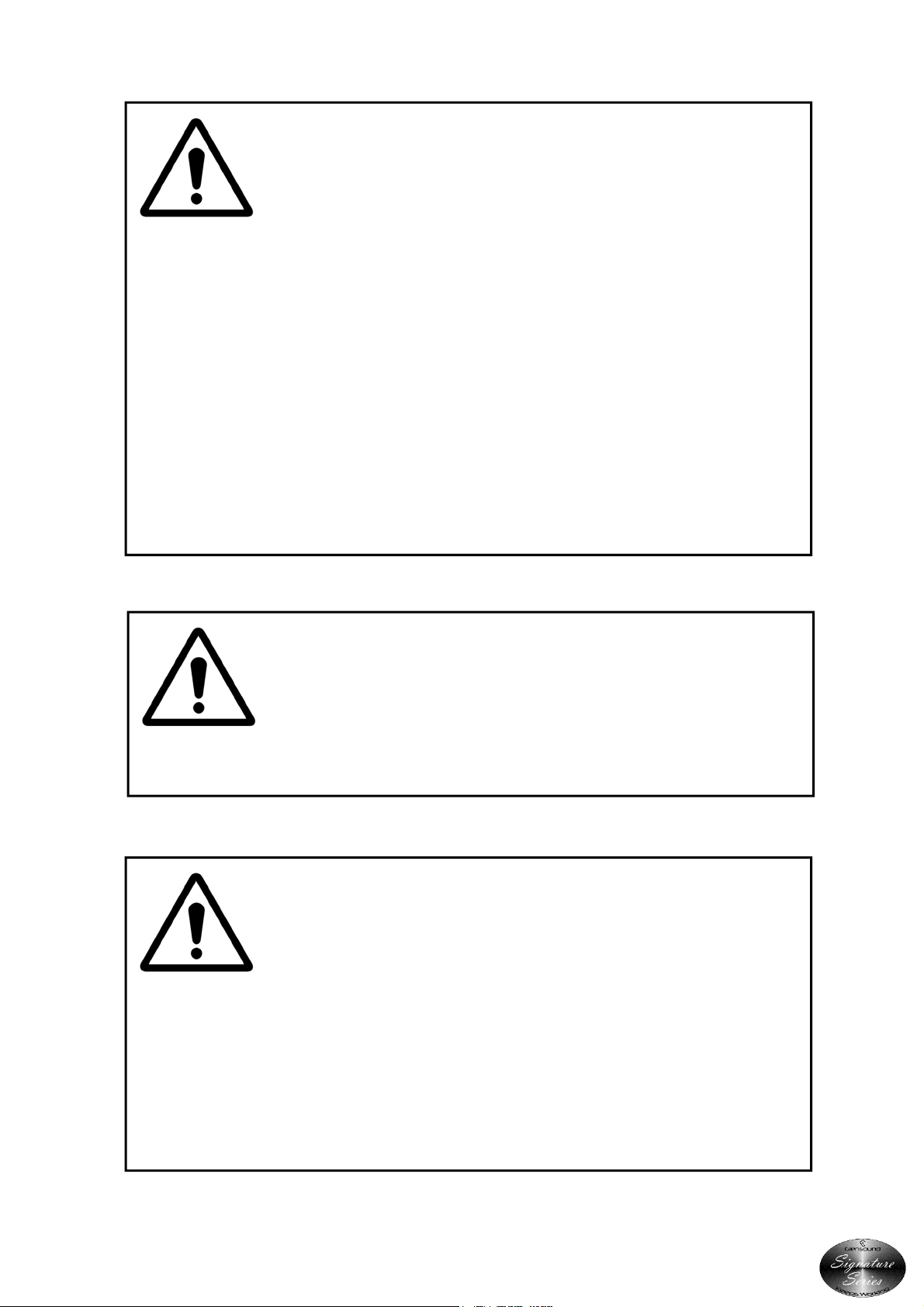
IMPORTANT: MAINS PLUG WIRING INSTRUCTIONS
This Signature unit is supplied with a moulded mains plug fitted to the AC mains
lead.
Mains wiring colours/ connections:
The Green/ Yellow or Green wire must be connected to the terminal in the plug
marked ‘E’ or with the Earth Symbol.
The Blue or Black wire must be connected to the terminal in the plug marked ‘N’
(Neutral).
The Red or Brown wire must be connected to the terminal in the plug marked ‘L’
(Live).
THIS UNIT MUST BE EARTHED
THIS UNIT IS FITTED WITH AN INTERNAL MAINS FUSE.
The fuse is located internally between the Live terminal of the IEC plug and the
Live input of the power supply. The fuse should only be changed by a qualified
service engineer. If replacing the fuse care should be taken to fit a correctly rated
replacement. The fuse rating can be found in the technical specifications page of
this handbook.
Page 4 of 20
Page 5

CE
Lead
0.1%
Mercury
0.1%
Hexavalent Chromium
0.1%
Polybrominated Biphenyls
0.1%
Pol
ybrominated Diphenyl Ethers
0.1%
Cadmium
0.01%
This equipment manufactured by Glensound Electronics Ltd of Brooks Place
Maidstone Kent ME14 1HE is CE marked and conforms to:
Low Voltage Directive: EN60065
Emissions: EN55103.1
Immunity: EN55103.2
WASTE ELECTRICAL AND ELECTRONIC EQUIPMENT
REGULATIONS 2006 (WEEE)
Glensound Electronics Ltd is registered for business to business sales of WEEE in
the UK our registration number is:
WEE/JJ0074UR
RoHS2 DIRECTIVE
EC directive 2011/65/EU restricts the use of the hazardous substances listed below
in electrical and electronic equipment.
This product conforms to the above directive and for this purposes, the maximum
concentration values of the restricted substances by weight in homogenous
materials are:
Page 5 of 20
Page 6

PRODUCT WARRANTY:
All equipment is fully tested before dispatch and carefully designed to provide you
with trouble free use for many years.
We have a policy of supporting products for as long as possible and guarantee to
be able to support your product for a minimum of 10 years.
For a period of one year after the goods have been despatched the Company will
guarantee the goods against any defect developing after proper use providing
such defects arise solely from faulty materials or workmanship and that the
Customer shall return the goods to the Company’s works or their local dealer.
All non-wear parts are guaranteed for 2 years after despatch and any defect
developing after proper use from faulty materials or workmanship will be repaired
under this warranty providing the Customer returns the goods to the Company's
works or their local dealer.
Page 6 of 20
Page 7

AoIP44
Handbook Contents
Issue 2,
Description Page No.
Contents
IMPORTANT SAFETY INSTRUCTIONS ........................................................................................................................ 3
PRODUCT WARRANTY: ...................................................................................................................................................... 6
OVERVIEW .......................................................................................................................................................................... 8
PHYSICAL INSTALLATION ................................................................................................................................................. 9
AUDIO BLOCK DIAGRAM ................................................................................................................................................ 11
EXAMPLES OF USE ........................................................................................................................................................... 12
1. Interface To Existing Dante Newtork ........................................................................................................................ 12
2. Interface To News/ Voiceover Studio ....................................................................................................................... 13
USER INDICATORS ........................................................................................................................................................... 14
1. Power On LED ..................................................................................................................................................... 14
2. Network LED ....................................................................................................................................................... 14
REAR PANEL CONNECTORS ............................................................................................................................................ 15
3. Network ............................................................................................................................................................... 15
4. Audio Outputs .................................................................................................................................................... 15
5. Audio Inputs ....................................................................................................................................................... 15
6. DC In .................................................................................................................................................................... 15
7. Mains In ............................................................................................................................................................... 15
CONNECTING THE AoIP44 TO A DANTE NETWORK ...................................................................................................... 16
Getting Dante Controller ............................................................................................................................................ 16
Connecting AoIP44s To A Network ............................................................................................................................ 16
Audio Over IP Network ................................................................................................................................................ 16
Running Dante Controller ........................................................................................................................................... 17
Dante Controller TIP .................................................................................................................................................... 17
UPDATING THE ULTIMO CHIPSET ............................................................................................................................ 18
WIRING INFORMATION ................................................................................................................................................... 19
TECHNICAL SPECIFICATION ............................................................................................................................................ 20
Page 7 of 20
Page 8

OVERVIEW
The Glensound AoIP44 is an economical subrack designed to interface balanced analogue
audio circuits to and from a network audio system featuring Dante. It provides 4 audio inputs
to the network and also 4 audio outputs from the network on balanced 3 pin XLRs.
The AoIP44 can be used as a simple low cost audio I/O break out unit on a large Dante audio
network where it can be integrated extremely easily using the Dante Controller and is fully
compatible with any manufacturers Dante equipment.
The AoIP44 can also be used in very simple audio over IP scenarios where 4 bi-directional
audio circuits are needed to be distributed across a buildings network infrastructure, in which
case 2 x AoIP44 units can be used connected together across the network. The AoIP44 is
equally suited for high integrity broadcast purposes, intercom, just simple paging facilities or
simple distribution of audio.
Being part of our Signature Range, the AoIP44 comes as standard with removeable rack ears
(to allow front or rear mounting in 19" racks), mounting holes to allow under desk mounting
(the holes are equally suited for screwing the unit into odd places!) and an optional external
DC power supply for applications requiring redundant power supplies. It is housed in an all
anodised aluminium chassis.
As with Glensound’s other Dante products 0dB = -18dBFs.
Page 8 of 20
Page 9
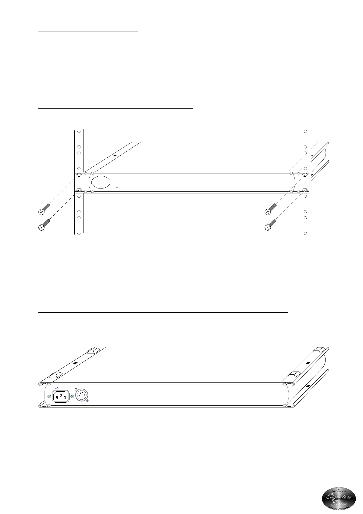
PHYSICAL INSTALLATION
The Glensound Signature Series have been designed to be highly versatile for installation and
can be installed in 19” racks with either their front or rear panels facing the front of the rack.
They can also be mounted underneath desks or work tops and can be either permananetly
mounted or stood (using the supplied feet) on top of desks or worktops.
INSTALLING SIGNATURE SERIES IN A 19” RACK
PART No
g
Signature
Series
PWR ON
Keeps Working
Firmly hold the signature subrack within the 19” rack and locate in 1RU of space. Use the
supplied 6mm rack screws to securly attach the unit to the rack.
INSTALLING ADHESIVE FEET FOR NON PERMANENT TABLE TOP MOUNTING
+/-12V
50/60Hz 2.7 Watts
- - -
100-240V
CE
W
PIN 3 = -12V (100mA)
PIN 2 = +12V (100mA)
PIN 1 = GND
Top
Remove the front rack ears (if they are not required), turn the unit upside down and attach
the supplied 4 adhesive feet as per the above drawing.
Page 9 of 20
Page 10
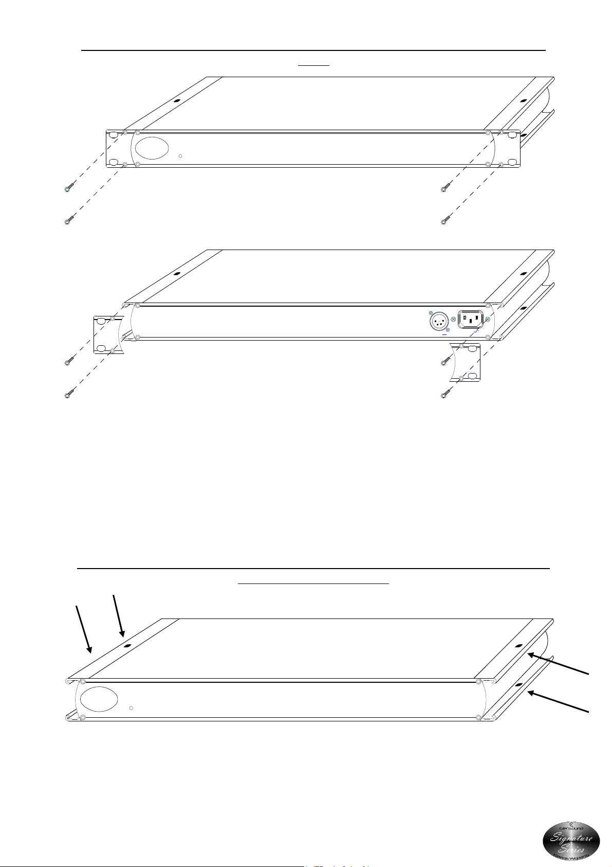
SWAPPING RACK EARS TO ALLOW THE REAR TO BE INSTALLED AT THE FRONT OF A
RACK
PART No
g
Signature
Series
Keeps Working
PWR ON
PIN 1 = GND
PIN 2 = +12V (100mA)
PIN 3 = -12V (100mA)
+/-12V
W
CE
100-240V
- - -
50/60Hz 2.7 Watts
First remove the 4 silver button head screws that fix the rack ears onto the front of the unit as
shown in the top picture above.
Remove the rack ears and turn the unit around for access to its back panel.
Re-fit the 2 rack ears using the same 4 silver button head screws that were removed from the
front as per the bottom picture above.
USING THE MOUNTING HOLES FOR PERMANENTLY ATTACHING THE UNIT ABOVE OR
BELOW A WORKTOP/ DESK
PART No
g
Signature
Series
Keeps Working
PWR ON
Use either the top or bottom mounting holes as indicated above to use suitable screws to
attach the signature unit to a worktop or bench. **PLEASE ENSURE THAT YOU USE SUITABLE
FIXINGS**
Page 10 of 20
Page 11
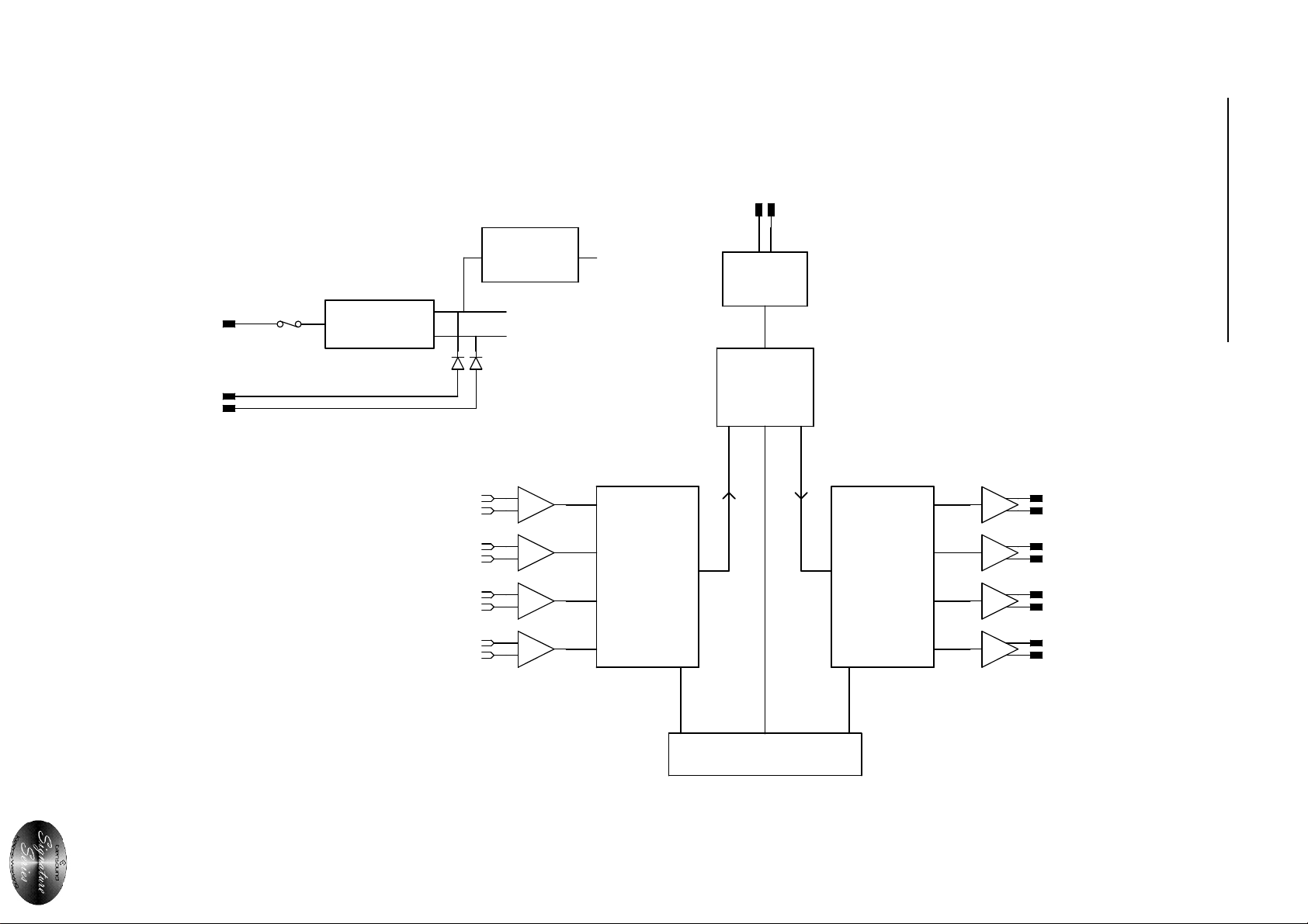
EXT DC +/-12V
DANTE NETWORK AUDIO
AUDIO BLOCK DIAGRAM
100 - 240 VAC
INTERNAL
FUSE
ANALOGUE AUDIO IN
AC/DC PSU
DC:DC
CONVERTER
+12V
-12V
+5V
ANALOGUE
TO DIGITAL
CONVERTER
NETWORK
PHY
AUDINATE
ULTIMO
CHIPSET
I2S Audio
I2S Audio
DIGITAL TO
ANALOGUE
CONVERTER
ANALOGUE AUDIO OUT
Page 11 of 20
Control Data
MICROPROCESSOR
Control Data
Control Data
Page 12
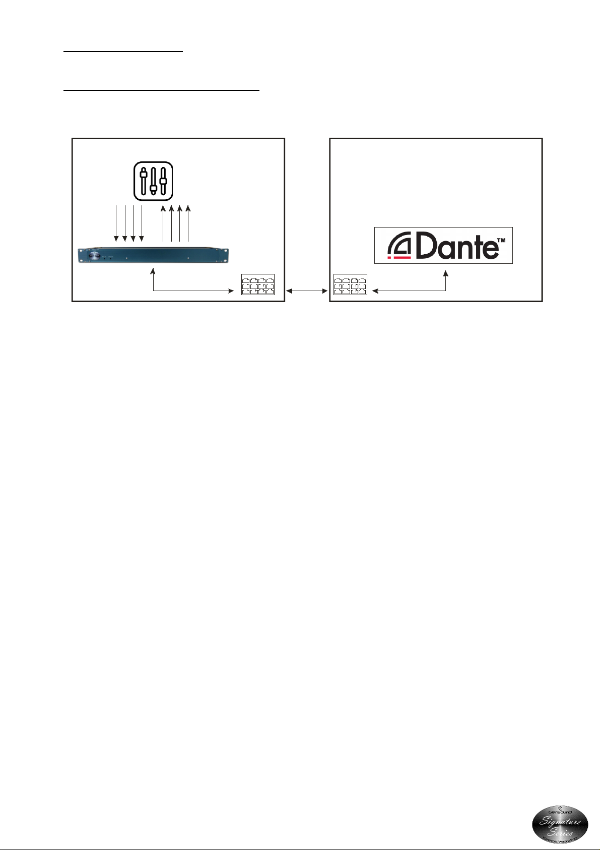
EXAMPLES OF USE
1. Interface To Existing Dante Newtork
Commentary Unit Connection To An Existing Dante Network
Commentar y Booth / Voiceover Booth Existing Dante Network
Any Dant e audio netw ork, w ith compatible
device from manuf act urers like:
network connection
4 x XLR3
(balanced or
unbalanced)
1 x programme in
3 x talkback in
Commentary
Mixer
4 x XLR3
(balanced or
unbalanced)
4 x monitoring
sources
1 x CAT5/6
network connection
Commentary
Booth
Switch
CAT5/6 or fibre
network
connection
Network
Switch
RTS
Stagetec
Calrec
Digic o
SSL
Yamaha
and over 150 more.
1 x CAT5/6
There are over 150 manufacturers that design Dante compatible equipment. In this example,
the broadcaster has an established Dante network. This is most likely to be an audio console,
or an intercom system.
The broadcaster needs to expand the network by adding an existing commentary booth /
voice over position. Using the AoIP44, the commentary position can be added to the existing
Dante network very cost effectively.
The AoIP44 is located in the commentary booth, and connected into the broadcast network
via a single CAT5/6 cable.
The Glensound GS-CU001B is the most widely used commentary unit by broadcasters. It
provides a programme mix output (direct outputs also available), and has 3 talkback outputs.
These connect to the inputs of the AoIP44 via XLR connections.
The AoIP44 outputs connect to the headphone monitoring inputs on the GS-CU001B via XLR.
This allows the commentators to hear 4 channels. These are typically the programme audio,
and talkback returns.
The audio routing can be configured via the Dante Controller software. Simply run Dante
Controller on any PC connected to the network. All available sources and destinations will be
shown on the AoIP44, and all other Dante compatible devices on the network. Click the
check boxes to route the audio in the desired directions, and the system is now ready to be
used.
Audio routing only needs to be configured by Dante Controller on the first time the AoIP44 is
connected to the network as all routes are stored locally on the device.
Page 12 of 20
Page 13
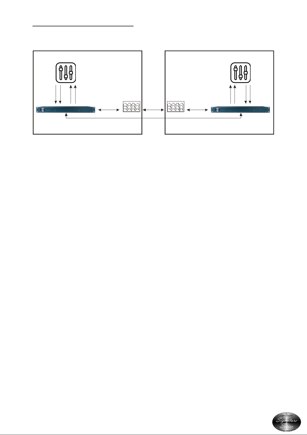
2. Interface To News/ Voiceover Studio
Programme Send With Stereo Return Monitoring
News Studio Control Room
2 x XLR3
(balanced or
unbalanced)
1 x mic in
1 x talkback in
2 x XLR3
stereo
programme
(balanced or
unbalanced)
1 x CAT5/6
network
connection
New s
Studio
Switch
CAT5/6 or fibre
network
connection
Or,
CAT5/6 direct
connection
(up to 100m)
Control
Room
Switch
1 x CAT5/6
network
connection
2 x XLR3
(balanced or
unbalanced)
1 x mic out
1 x talkback out
2 x XLR3
stereo
programme
(balanced or
unbalanced)
A small voice over studio is used is used for production of voice recording and by the
newsreaders. This is a separate studio to the main studios, and separate from the control
room.
As there are only a few channels to transmit between the locations the AoIP44 is a cost
effective option for connecting the bi-directional audio.
The mixer in the voice over studio only has 2 outputs: the direct output of the microphone,
and a separate talkback channel. These connect to the local AoIP44 via XLR. There is a local
network switch in the voice over studio and this connects via a spare port to the AoIP44 via
CAT5/6, so that it is now recognised on the local network.
A second AoIP44 connects to the local network switch in the control room via a CAT5/6
connection. Two of the audio outputs from the AoIP44 are connected to the control room
mixer via XLR. We will configure this as the 2 channels of audio coming from the voice over
studio. The stereo programme output from the control room mixer is connected to two of
the AoIP44 inputs via XLR. All of the physical audio connections have now been made.
As both AoIP44s are connected on the network, the audio routing can be configured via the
Dante Controller software. Simply run Dante Controller on any PC connected to the network
and both AoIP44s will be displayed showing available sources and destinations. Click the
check boxes to route the audio in the desired directions, and the system is now ready to be
used.
Over shorter distances, network switches are not even required and 2 x AoIP44s can connect
directly. Audio routing still needs to be configured by Dante Controller on the units when
they are connected to a network, but this is only required once to set the required routing.
Page 13 of 20
Page 14
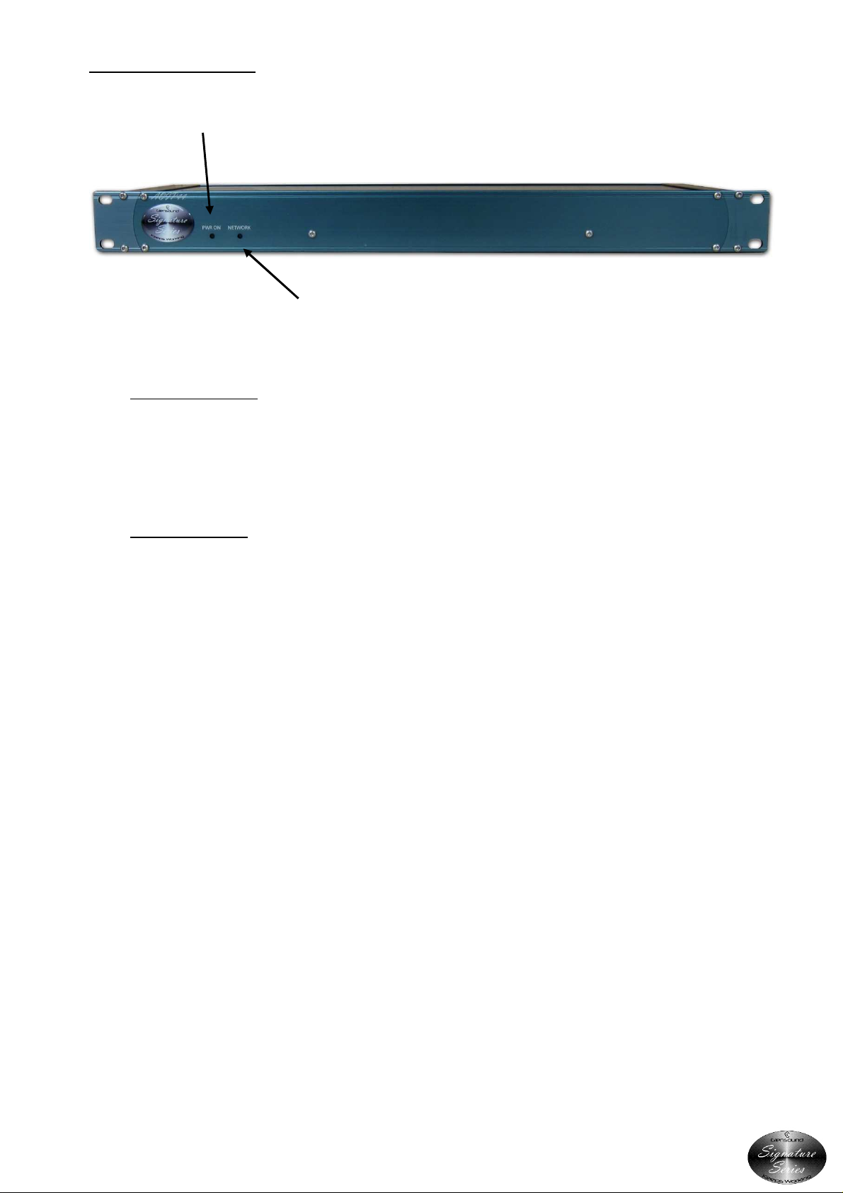
USER INDICATORS
1. Power On LED
2. Network LED
1. Power On LED
The front panel bright blue LED lights when power is available from either the internal mains
power supply or the external DC input.
2. Network LED
The front panel Network LED is on when data is being transferred to/ from the network. It is
not unusual for this LED to flicker quickly.
Page 14 of 20
Page 15
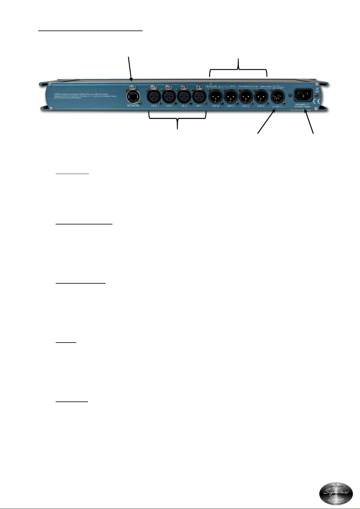
REAR PANEL CONNECTORS
4. Network
3. Audio Outputs
5. Audio Inputs
6.
DC In
7.
Mains In
3. Network
The Neutricon RJ45 connector provides connectivity to your IP network
4. Audio Outputs
Four balanced analogue audio outputs are provided for the return audio from the Dante
network on Neutrik XLR plugs.
5. Audio Inputs
Four balanced analogue audio inputs are provided for sending audio into the Dante network
on Neutrik XLR sockets.
6. DC In
An external DC power supply such as our Signature PS1 can be connected here to provide
either the power to the AoIP44 or a redundant power supply if the mains input is also used.
7. Mains In
The filtered IEC inlet allows connection to external mains supplies of between 100 & 240 VAC
(+/- 10%)
Page 15 of 20
Page 16

CONNECTING THE AoIP44 TO A DANTE NETWORK
The AoIP44 is a network audio device utilizing the reliable and versatile Dante audio over IP
protocol. Dante is a proprietary system (although very widely used) the originators of which
are Audinate.
The information below is only meant as a very basic guide. Full details of the power of Dante
network audio and instructions for using it can be found at www.audinate.com
Getting Dante Controller
If you are connecting the AoIP44 to a new Dante network the first thing you will need to do is
to get the free Dante controller software from Audinate.
This can be downloaded by visiting Audinate’s web site at www.audinate.com
Connecting AoIP44s To A Network
AoIPs can be connected to the network that you are going to use for your audio distribution
simply by plugging in the network connection on the rear. Once connected to the network it
will be possible to see the AoIP44 from within the Dante controller and route the audio
circuits.
Audio Over IP Network
We strongly recommend that you consider your network topology carefully and would not
recommend sharing broadcast audio and general data on the same network.
For more details of audio over IP network structure please visit www.audinate.com
Page 16 of 20
Page 17
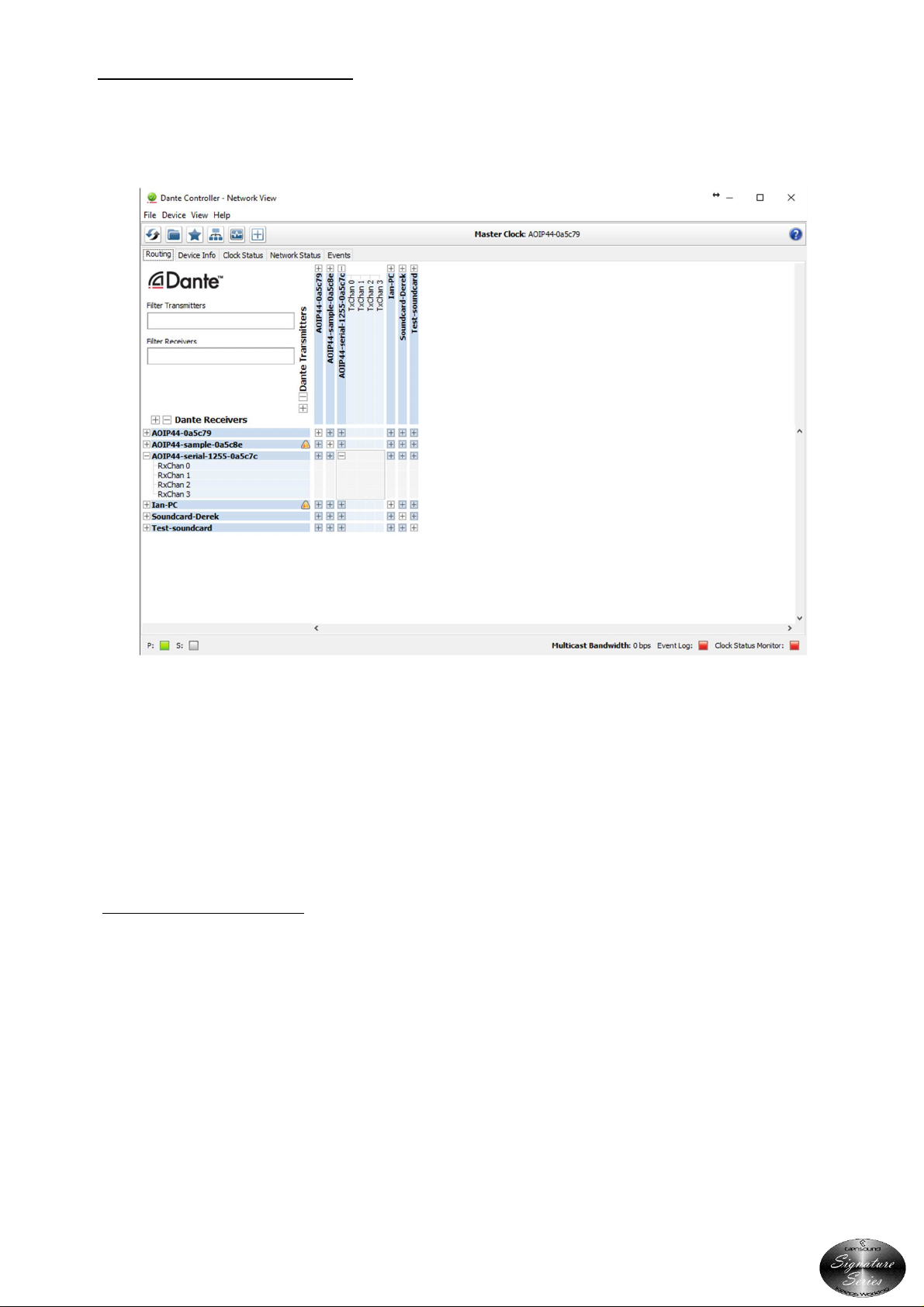
Running Dante Controller
At the time of writing this manual, Dante Controller looks as per the screenshot below:
The AoIP44 will have been named at the factory during test to allow them to be identified by
the Dante controller.
The format used for the factory name is:
‘AOIP44-serial-XXXX-YYYYYY’. ‘XXXX’ will be the units 4 digit serial number, and ‘YYYYYY’ will
be the AoIP44’s MAC address.
Dante Controller TIP
If you have never run Dante controller before then make sure that on the bottom left of the
Dante controllers’ screen ‘P’ or ‘S’ is next to a green square as this indicates that it is
connected to a network. By clicking ‘P’ or ‘S’ a pop up box opens to allow you to set what
network interface the controller is using.
Page 17 of 20
Page 18

UPDATING THE ULTIMO CHIPSET
The Ultimo chipset is a device supplied by Audinate that does most of the processing for
the actual Dante
supply special code (a .dnt file) that sets up/ initiates the Ultimo chipset and makes it work
in particular way that is suitable for the AoIP44.
1. Finding Out What The Latest Available Version Is
Go the AoIP44’s’s web page at http://www.glensound.co.uk/product-details/aoip44/ and
open the ‘Firmware Latest Version’ Tab.
This will give both the latest version numbers/ file names and also the location to download
the file from.
2. Updating the Ultimo Chipset
TM
network audio streams. There is one Ultimo chipset in each AoIP44. We
The firmware that runs on the Ultimo chipset is updated using Audinate’s Firmware
updating tool. The updating tool and a user guide can be downloaded from Audinate’s
website:
https://www.audinate.com/products/firmware-update-manager
The actual firmware to install using the above tool can curently be downloaded from (but
check as per step 1 in case there is a more up to date version):
http://www.glensound.co.uk/Software/Dante/AOIP44_D=3.10_FW=1.0.0.dnt
When downloading the above file please make sure that you know where your computer
has saved it.
Please note we strongly advise that when you do the update that only your PC and the
Paradiso that you want to update are on the network to save accidently updating the wrong
Dante device.
Page 18 of 20
Page 19
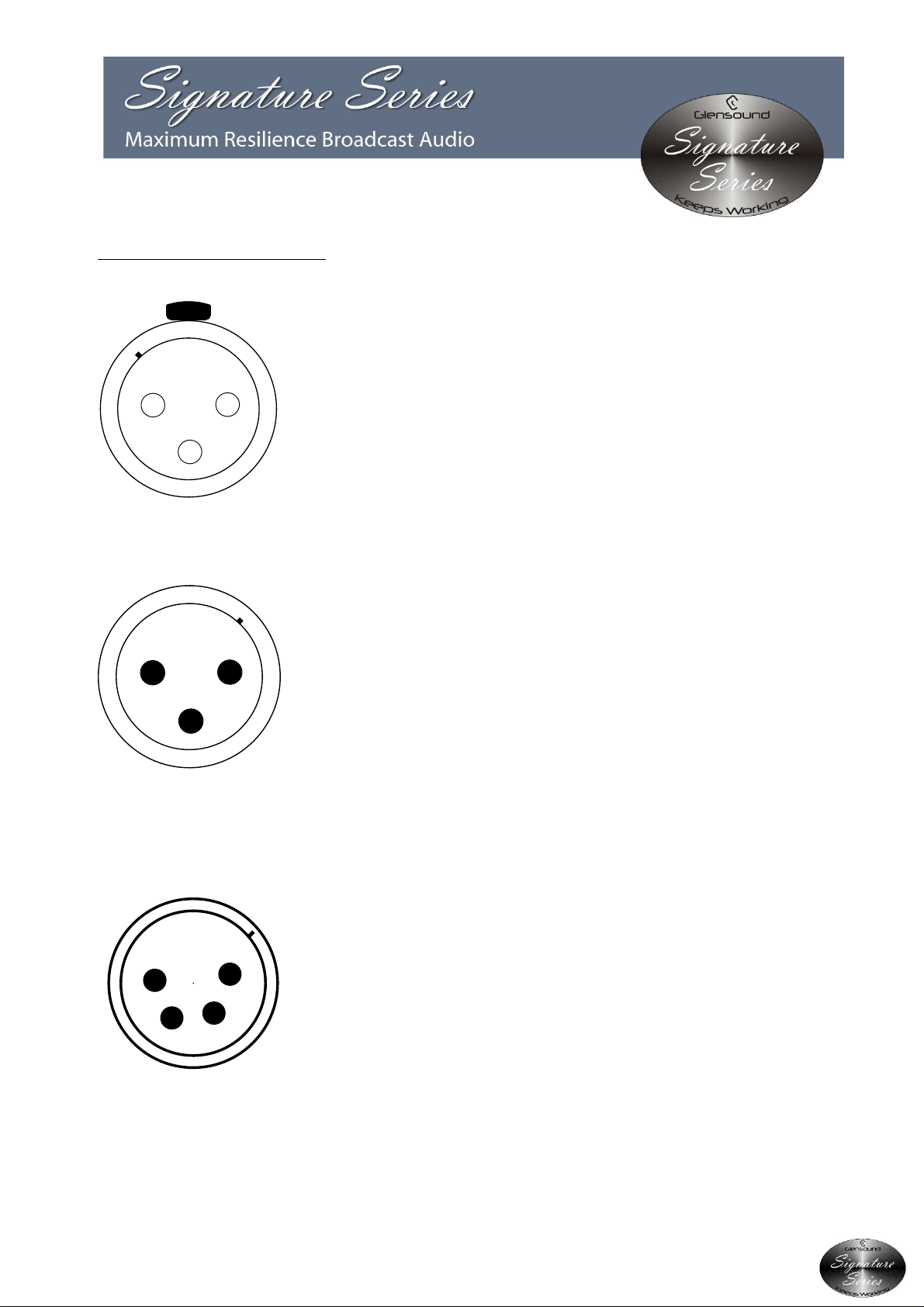
WIRING INFORMATION
XLR SOCKET (FEMALE)
STANDARD XLR AUDIO PINOUTS:
EXTERNAL DC INPUT
:
4 PIN XLR PLUG (MALE)
12
3
1 2
3
XLR PLUG (MALE)
1
4
1: Ground/ Earth
2: INPHASE/ POSITIVE/ MIC +
3: MATE/ NEGATIVE/ MIC -
PIN 1: GND
2
3
PIN 2: +12V
PIN 3: -12V
Page 19 of 20
Page 20
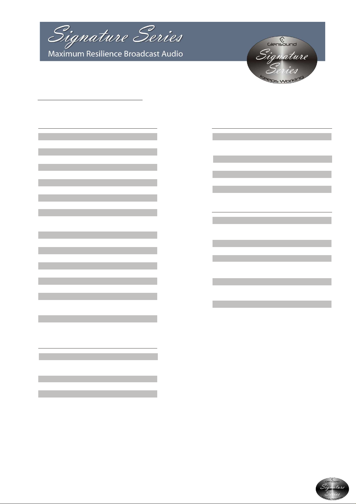
TECHNICAL SPECIFICATION
POWER
AUDIO
Frequency Response <= 0.25dB
Flat until 22k
Maximum Input Before Clip
+18dBu
Maximum Output Level
+18dBu
Input Impedance
>20k Ohm
Output Impedance
50 Ohms
Distortion
0.013% THD @ 100Hz, 1kHz & 10kHz
Reference to +8dBu output
Noise Residual
-94.6dBu
THD+N Relative (1k +8dBu)
0.00134%
Dynamic Range
112.6dBs
Crosstalk (0dBu input to output 1k tone)
-94.7dBu
Output Type
Electronically balanced (can be wired
unbalanced) on Neutrik 3 pin XLR plug
Input Type
Electronically balanced (can be wired
Unbalanced) on Neutrik 3 pin XLR socket
Mains Input
Filtered IEC, 100 to 240VAC
47 - 63Hz
AC Consumption
4.3 Watts @ 230VAC
DC Input
FEATURES
4 Pin Neutrik XLR. +12v 240mA, -12v N/A
Internal Mains Fuse
20mm 1A Anti Surge
PHYSICAL
Size
445 x 123 x 44mm (LxDxH) no rack ears
482mm length (19” 1RU) with rack ears
Weight
1.2kg
Mechanics
All aluminium construction, anodized and
laser etched
Shipping Car ton
Rugged export quality cardboard carton
610 x 420 x 130mm LxDxH
Shipping Weight
2.7kg
E & OE
NETWORK AUDIO
Compatible Audio Networks
Dante uncompressed, low latency audio.
For full details visit ww w.audinate.com
Network Connection
Neutrik RJ45 EtherCON
Dante Network Sample Rate
44.1k, 48k, 88.2k, 96k
Page 20 of 20
 Loading...