

instructions booklet
notice D’utilisAtion
1

English - EN
We would like to thank you for purchasing one of our products,
we are condent it will full your needs. We would also like to
invite you to read this booklet carefully and keep it safe, as it
contains important information and useful tips for your new
cooker optimal use, in complete safety.
This appliance is in conformity in force:
- 2006/95/CE Low Voltage (Directive)
- 2004/108/CE Electromagnetic Compatibility (Directive)
- 2009/142 Gas Appliance (Directive)
- 1935/2004/CE Materials intended to come into contact with
food (Regulation)
- 2002/95/CE Restriction of the use of certain hazardous
substances in electrical and electronic equipment (Directive)
- 2002/40/CE Energy labelling of household electric ovens
(Directive)
TABLE OF CONTENTS
03 General warnings
04 Your product
05 Use
Hob
Oven
Programmers and minute minders
Cooking suggestions
08 Cleaning
09 Maintenance
10 Instructions for the installer
Product handling
Installation
Adaptation to the different types of gas
14 Technical assistance
14 Product and packaging disposal
14 Technical data
16 Cooking and grilling tables
2

GENERAL WARNINGS
This appliance is only designed and built for household use. Any other
use, such as heating, for example, is considered improper, and therefore
highly dangerous.
Keep children away with under the age of 8 years, if not under the constant
supervision of an adult.
Children and people with reduced physical, mental or sensory abilities
and/or with lack of adequate knowledge of the use and dangers that the
equipment can entail, are forbidden to use this appliance unless they are
under the constant supervision of a responsible adult.
Children must not play with or near the appliance, whether it is in operation
or not. Please do not allow children to clean the appliance.
If the appliance has a fault and/or is not working properly, please close
the gas line, disconnect the appliance from the power mains, and do
not attempt to service it by yourself. Contact your nearest authorized
assistance centre directly (see the "technical assistance" section herein).
The surface temperatures of every part must strictly comply with the
regulations in force. This does not mean that some metal parts will not
burn during or after its use. Accordingly, please use with due care.
The cooker cannot be installed without feet;
The Company will not be held liable in case of failure to observe the
information provided herein.
The Company reserves the right to change product specications
maintaining safety and functionality.
3
CAUTION
Some parts of the cooker are protected by a special film. Take it out before operating the appliance and use lukewarm
soapy water to remove any sticky residue.
Preventing accidents in the home
Do not leave the appliance unattended when cooking with fats or oil: it may cause a fire.
Do not leave objects near the cooking surfaces.
If glass ceramic hobs crack, turn the appliance off to prevent possible electric shock.
NEVER try to put out a flame/fire with water; rather, turn the appliance off and cover the flame with a lid or flame-proof blanket.
Prevent pots from protruding from the hob edges during use. It is also advisable to use containers with an intact, at base.
During use the appliance overheats. Children must be kept away from the appliance. Be careful to avoid touching the
heating elements inside the oven.
The accessible parts can be hot when the grill is used, therefore children must be kept away.
Do not use jets of steam to clean the appliance. Steam could reach the electrical parts, damaging them and causing short
circuits. Do not use cleaning products that contain chlorine, ammonia or bleach on parts made of steel or supercially treated
with metal nishes (for example anodizing, nickel plating, chrome plating).
It is essential that all installation, adjustment and technical maintenance operations are carried out by qualied personnel
only. The appliance must be installed in compliance with the regulations in force in the country of use.
Prior to every maintenance operation it is necessary to unplug the appliance from the power socket and wait for it to cool
down completely.
To prevent accidental tipping of the appliance to install a stabilizing device, as shown on page 11 in the installation section.
The appliance is designed to operate with different types of gas; each type of gas requires specic injectors and adjustments.
To make any change, it is always necessary to disconnect the appliance from the power mains, and temporarily cut off the gas
supply from the mains.
If your cooker has a glass lid, make sure it is lifted open before turning on the burners, during use and the subsequent
cooling phase. Failure to do so may cause breakage of the glass.
Do not use abrasive products or sharp metal spatulas to clean the oven door glass as this may scratch the surface, causing the
glass to shatter.
Remove any liquids that may have overown onto the lid before opening it. Let the surface of the hob cool down before closing the lid.
The rst time you use the oven, take out all of the accessories and supplied materials placed inside of it, turn it on and let
it run idle for at least one hour at the highest temperature, with the door closed (but not using the grill). Then, switch it off, open
the oven door and ventilate the room. Any odour you can smell is from the evaporation of the sealing and protective substances
inside the oven.
The appliance is not conceived to operate with an external timer or remote control system.
The use of a gas appliance produces heat and moisture in the room where it has been installed. Please ensure good
ventilation of the room keeping open the orices of natural ventilation or installing a mechanical ventilation device (extraction
hood with exhaust duct).
During cooking do not cover the bottom of the oven or hob with aluminum foil.
4
YOUR PRODUCT
Given the wide range of products available on the market, this booklet contains information about several models, and it is therefore possible that not all of the
information contained herein refers to your appliance or its accessories. We are nevertheless at your disposition for any clarication you may require.
Your cooker consists of the following main parts:
• hob: at top part where the pan supports (supports for the pots), the gas burners, electric plates or the glass-ceramic areas, depending on the size and model of
your cooker are locatedV.
• control panel: cooker control devices zone (i.e. knobs and switches).
• oven door
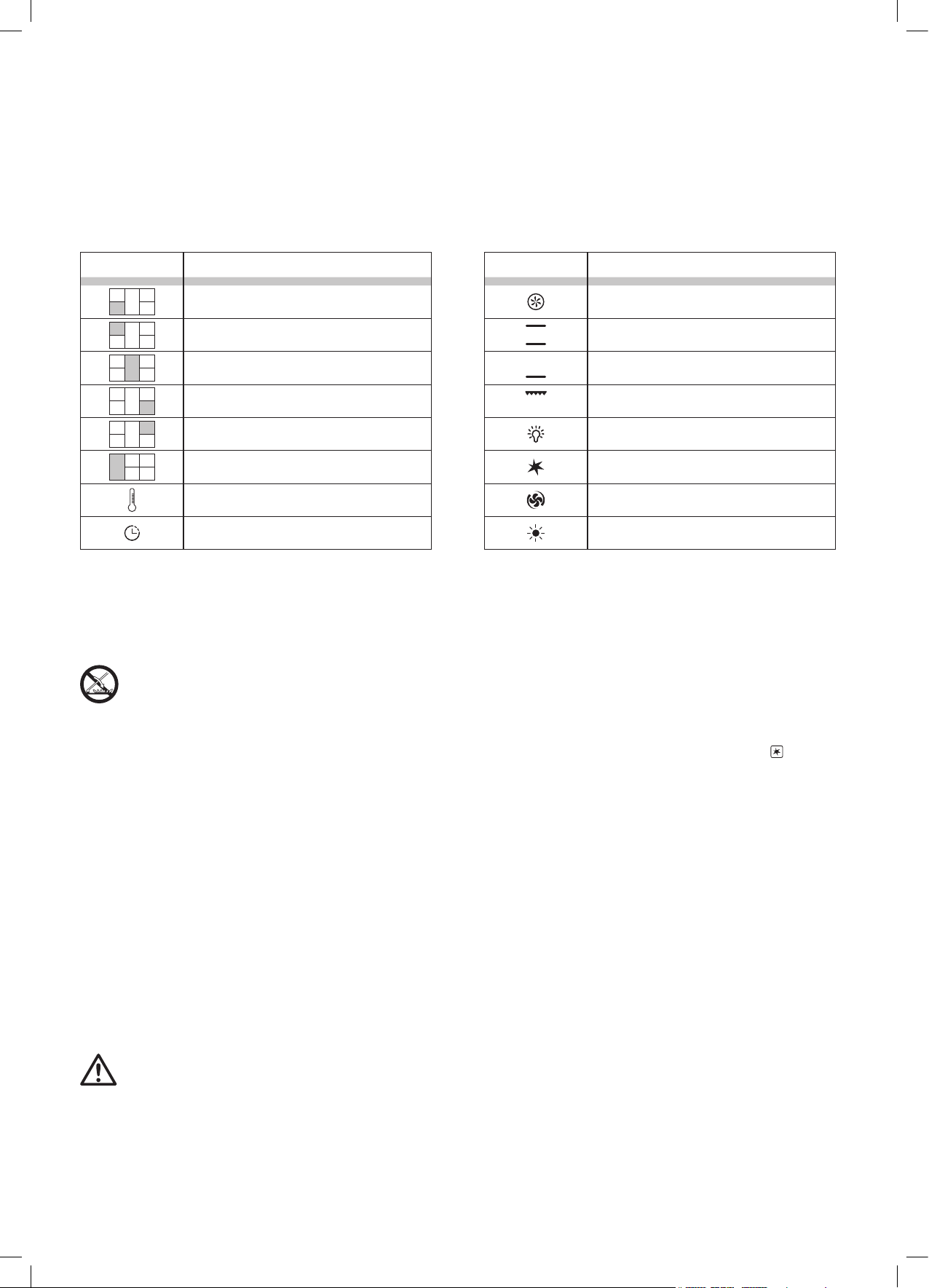
HOW TO IDENTIFY THE SYMBOLS ON THE CONTROL PANEL
SYMBOL MEANING
Burner / front left area
Burner / rear left area
Central burner
Burner / front right area
Burner / rear right area
Burner / left area
Oven temperature control (°C)
Timer / minute minder
USE
HOB
USING THE HOB
If your cooker has a glass lid, make sure it is lifted open before turning on the
burners, during use and the subsequent cooling phase. Failure to do so may
cause the breakage of the glass.
SYMBOL MEANING
Multi-function electric oven features
Oven thermostat
Gas oven burner
Grill burner
Light button
Ignition button (spark)
Ventilated gas button (MultiChef)
These two pilot lights indicate that the electric oven
is on and/or that the oven is heating up
TURNING ON THE GAS BURNER
Place a lit match near the burner (or a spark or a ame generator), press and turn the corresponding knob counter-clockwise to the MAX position.
The hob can be equipped with electrical ignition activated through a separate button or by pressing the knob.
When it is lit, hold the knob down for approximately 10 seconds, then release it and adjust ame intensity, being careful to position the knob in the area between
maximum and minimum (included) and never between maximum and zero to prevent turning it off unexpectedly.
The burner may go out when you release the knob: this means that the thermocouple is not hot enough.
If it does not ignite within 15 seconds, wait 1 minute before trying again.
If your model does not have a gas safety valve (copper-coloured thermocouple near the burner), please check that, at regular intervals, the ame does not go out
due to possible liquid overowing from the pots during cooking.
USE OF ELECTRIC PLATES
The electrical plates are switched on by turning the knob clockwise, at a value between 0 and 4.
The higher the number, the greater the applied electrical power.
By turning a plate on for the rst time or after a long period of inactivity, it is advisable to make it run idle without cooking on it, on the “minimum heating” position
(position 1) for at least 15 minutes, so as to eliminate any humidity that the insulation may have absorbed. To optimize the use of electric plates, use at-bottomed
pots and avoid using pots with diameters smaller than the plates.
USING GLASS-CERAMIC HOBS (HIGHLIGHT)
Please refer to the booklet supplied with the appliance.
PREVENTING HOME ACCIDENTS
Do not leave the appliance unattended when cooking with fats or oil: it may cause a re.
Do not leave objects near the cooking surfaces.
If glass ceramic hobs crack, turn the appliance off to prevent possible electric shock.
PRACTICAL TIPS FOR USING THE HOB
For best use of the burners with minimum gas consumption, it is advisable to use at-bottomed pots with lids, and a suitable size for the burner. The table below
provides the pot diameters for each burner, from the smallest to the largest.
5
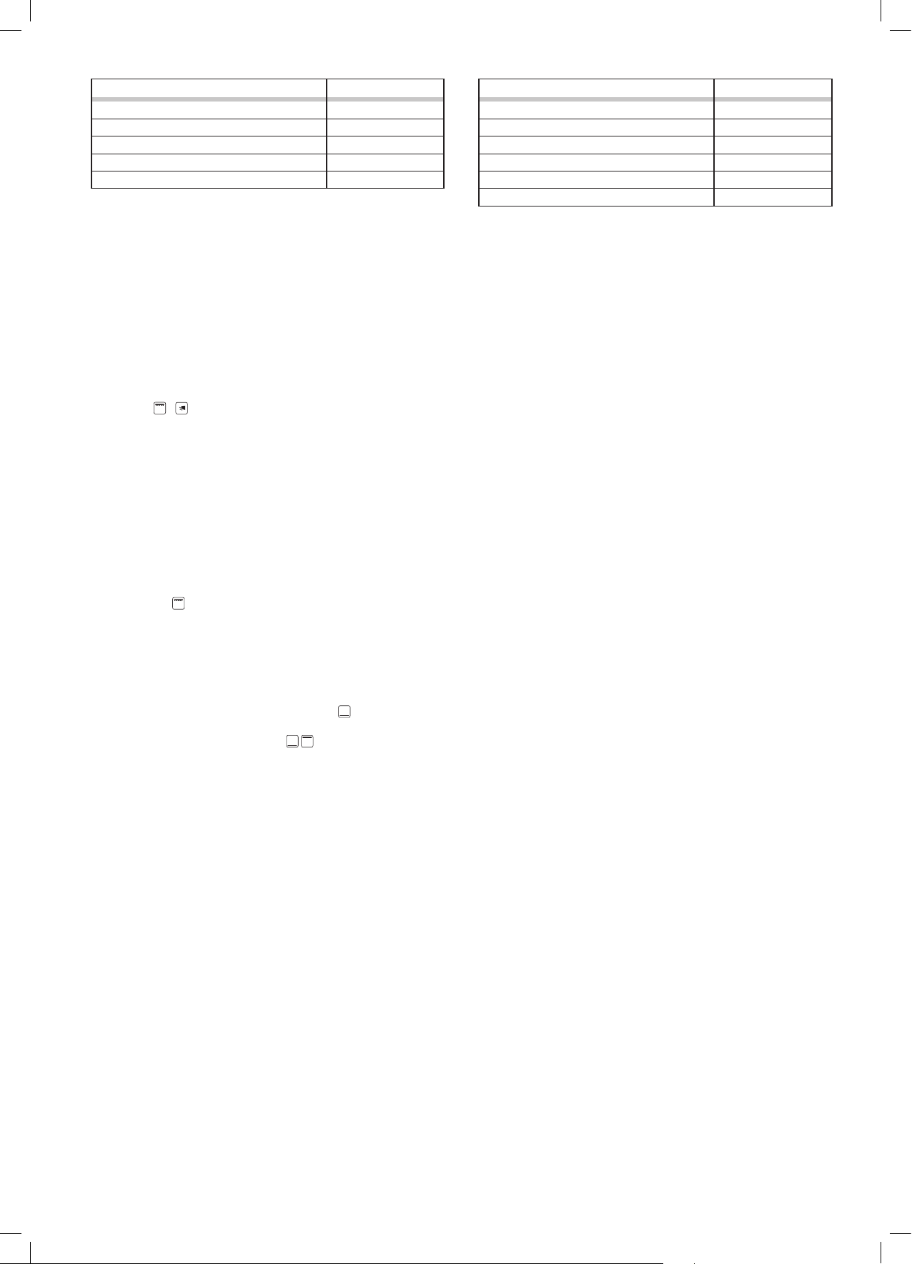
Type (burner size in cm) Pot size (cm)
Auxiliary burner (A) Ø 5 Ø 10 - 14**
Semi-rapid Burner (S) Ø 7.5 Ø 16 - 20
Rapid Burner (R) Ø 10 Ø 20 - 24
Triple Crown Burner (TC) Ø 13 Ø 24 - 28
Fish Burner (FB) 6x23,5 max 14x35
** The reduction grill ,FOR models that include it, must only be used for the auxiliary
burner when cooking with pots with a diameter less than 12 cm.
Type (screen-printing area size in cm) Pot size (cm)
Electrical plate Ø 14.5
Electrical plate Ø 18 Ø ≥ 18
Glass-ceramic area (highlight) Ø 14.5 Ø ≥ 14.5
Extendible glass-ceramic area (highlight) Ø 12 - 21 Ø ≥ 12 - 21
Glass-ceramic area (highlight) Ø 21 Ø ≥ 21
Extendible glass-ceramic area (highlight) Ø 17 - 26.5 Ø ≥ 17 - 26,5
Ø ≥ 14.5
OVEN
TURNING THE OVEN ON
The rst time you use the oven, take out all of the accessories and supplied materials placed inside it, turn it on and let it run idle for at least one hour at the
highest temperature, with the door closed (but not using the grill). Then, switch it off, open the oven door and ventilate the room. Any odour you can smell is from
the evaporation of the sealing and protective substances inside the oven.
COOKER WITH GAS OVEN AND ELECTRIC GRILL
The gas oven is equipped with a heating element (oven burner) located under the base of the oven and with a top heating element (grill). Some models also have
a rear fan, which can be switched on and off with a key, and is used to evenly distribute heat during use. To check the oven, it is necessary to use a knob and 1
or 2 keys (
The oven burner must always be lit with the oven door fully open and the cavity empty. Press and turn the oven knob counter-clockwise to the MAX position.
Holding the knob down, bring a lit match (or a spark or a amegenerator) close to the hole on the base of the oven. Keep the knob pressed down for approximately
10 seconds, then release it and adjust to the required temperature. Close the oven door and wait few minutes to preheat the cavity before cooking foods.
Some models also have a rear fan which is used to evenly distribute heat during oven use.
If you need to carry out cooking with forced air, insert its control.
/ ).
If the burner does not ignite within 15 seconds, wait 1 minute before trying again.
In some models the burner can be equipped with ignition activated with a separate button or by pressing the knob itself. when it is lit, keep holding the knob down
for approximately 15 seconds. The burner may go out when you release the knob: this means that the thermocouple is not hot enough. wait at least 1 minute and
repeat the operation holding the knob down longer.
ELECTRIC GRILL
The Grill feature is switched on and off from its key. In cookers with an accessory to protect the knobs (glazed black knob protection) grilling must be done with
the oven door partially open. before starting the grill, assemble the knob protection on the slots located on both sides of the frontal part, between the control panel
and the oven itself.If your cooker does not have this accessory, it means that grilling must be done with the door closed.
COOKER WITH GAS OVEN AND GAS GRILL
This type of cooker has a burner located under the base of the oven and a grill burner on the ceiling of the oven.
Generally only one knob is used to control the oven
Some models have two separate knobs
, one for each burner, allowing the two burners inside the oven to be used at the same time. This particular option,
traditionally offered in certain markets, is useful for cooking large quantities of food and for bringing the oven to the required temperature quickly.
GAS OVEN
The oven burner must always be lit with the oven door fully open and the cavity empty. Press and turn the oven knob counter-clockwise to the MAX position.
Holding the knob down, bring a lit match (or a spark or a amegenerator) close to the hole on the base of the oven. Keep the knob pressed down for approximately
10 seconds, then release it and adjust to the required temperature. Close the oven door and wait few minutes to preheat the cavity, after that put foods inside the
oven on the desired level.
Some models also have a rear fan which is used to evenly distribute heat during oven use.
If you need to carry out cooking with forced air, insert its control.
GAS GRILL (oven door closed)
The grill burner must always be lit with the oven door fully open and the cavity empty. Press and turn the oven knob counter-clockwise to the MAX position. Holding
the knob down, bring a lit match (or a spark or a amegenerator) close to the hole on the base of the oven. Keep the knob pressed down for approximately 10
seconds, then release it and adjust to the required temperature. Close the oven door and wait few minutes to preheat the cavity, after that put foods inside the
oven on the desired level.
Some models also have a rear fan which is used to evenly distribute heat during oven use.
If you need to carry out cooking with forced air, insert its control.
GAS OVEN WHIT GAS GRILL (oven door closed)
The oven burner must always be lit with the oven door fully open and the cavity empty. Press and turn the oven knob counter-clockwise to the MAX position.
Holding the knob down, bring a lit match (or a spark or a amegenerator) close to the hole on the base of the oven. Keep the knob pressed down for approximately
10 seconds, then release it and adjust to the required temperature. Close the oven door and wait few minutes to preheat the cavity, after that put foods inside the
oven on the desired level and ignite the gas grill.
Some models also have a rear fan which is used to evenly distribute heat during oven use.
If you need to carry out cooking with forced air, insert its control.
6
COOKER WITH ELECTRIC OVEN
There are two types of electric ovens in our range: static (no fan) and multifunction. Static ovens only have one control knob which manages the features and
internal temperature, while multifunction ovens have two knobs: one to select the features and another to manage the temperature.
ELECTRIC OVEN WITH 1 KNOB (STATIC - NO FAN) TO CONTROL THE OVEN
Turn the knob clockwise and set the required temperature. Both lights on the control panel will turn on, indicating that the oven is on and is heating up. When
it reaches the required temperature, the light indicator will switch off.
In these models the Grill is switched on by turning the knob clockwise by three clicks. The grill (heating element) must be used with the oven door partially open.
In these cases it is essential that you apply a device to protect the knobs (glazed black knob protection) which is part of the standard supply of the the cooker
(it will be inside the oven). With the door open, the device must be inserted into the slots on both side of the front of the oven, between the control panel and the
oven itself.
Attention: when the grill is in use, the accessible parts may reach high temperatures.
MULTIFUNCTION OVEN
Multifunction electric ovens are controlled by a feature selector (knob) associated to a thermostat that allows you to choose the required temperature. Depending
on the oven model, it will have various cooking features (see the cooking features table to identify symbol and use).
Select the desired feature and temperature. If the cooker does not have any knob protection, this means that grilling is carried out with the door closed and it is
not possible to set temperatures above 200°C.
For immediate access to the cooking features in ovens with a programmer (manual, analogue or electronic), always make sure the programmer / timer is in
“manual” mode .
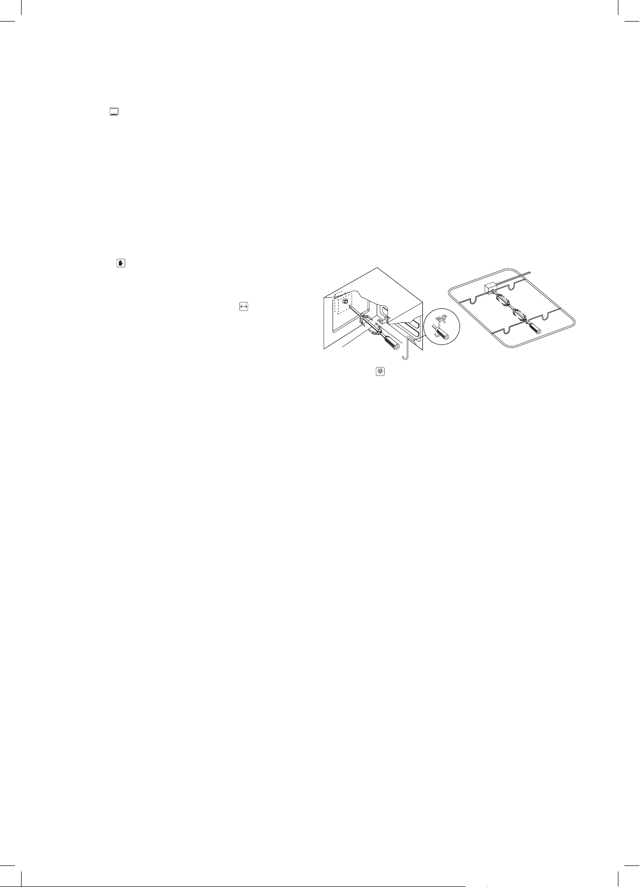
TURNSPIT
The turnspit can be switched on from a manual key
or in automatic by selecting the corresponding symbol .
Put the food on the turnspit so that it can be supported by the two forks;
balance the weight in the centre to avoid unnecessary strain
on the turnspit motor as it rotates.
LIGHT
The light inside the oven can be switched on and off by the relative key, or by turning the oven knob .
CROSS FLOW COOLING FAN
The cross ow cooling allows the surface temperatures of the cooker to decrease thanks to the forced air recirculation between the oven door, the control panel
and the oven cavity under the hob. The cross ow fan, located between the hob and the ceiling of the oven, automatically starts up a few minutes after the oven
is switched on, and a device keeps it running even when the oven is switched off, until the outside of the oven cools down.
PRH FEATURE (if applicable)
This feature pre-heats the oven quickly, allowing you to reach the ideal temperature to start cooking. To enable it (in models without the digital timer/prog and
mechanical cooking-end timer) turn the oven knob to the PRH feature to turn it on; the two Leds light uo (PRH-°C) and when the pre-heating cycle is nished they
will go off. It is now possible to put the food in the oven and select the desired cooking feature.
BOTTOM COMPARTMENT (under the oven door)
Some models have a bottom compartment where the cooker's metal accessories can be stored when not in use.
Do not place ammable material, paper, rags, plastic bags etc... inside this compartment.
PROGRAMMERS AND MINUTE MINDERS
MINUTE MINDER
The minute minder is switched on by turning the knob clockwise to the end of its run, in order to load the mechanism, then counter-clockwise to set the required
time. The time is expressed in minutes, a bell will let you know when the previously-set minutes are up.
COOKING-END MECHANICAL TIMER (only in models with an electric oven)
This mechanical timer, in addition to sounding the bell, also acts as a switch, by switching off the power. It is different from the minute minder because the ring
nut around the knob (washer), in addition to indicating the minutes, also has the symbol of a hand. To set it, turn the knob to the end of its run, in order to load the
mechanism, then turn it in the opposite direction to set the required time. If you wish to turn the oven on without setting any time, position the knob on the 'hand'
symbol in the manual position.
3 KEYS OF THE DIGITAL TIMER (g. 3 - page 8)
• Set the time: press the timer on/off button (bell) immediately followed by the + or – key to adjust the time. Once it has been set, the time will automatically
be set after 10 sec.
• Use the timer: to set the cooking time, press the + or – key until you reach the required amount of time (between 1 and 99 minutes). When the timer is on, it
will appear on the screen. When the time is up, the timer will start ringing. To turn it off, press the timer on/off key (bell).
• Changing the volume of the timer: set the timer at 1 minute and when you hear the bell, press the - key to change the volume.
TOUCH PROGRAMMER (g. 4 - page 8)
The touch programmer can work in 3 modes:
- MINUTE MINDER: once the time is set the timer will start counting down until it is up, and a bell will ring.
- AUTOMATIC END-COOKING: when the time is up, the oven will switch off and a bell will ring (only in models with electric ovens).
- DELAYED START: by setting the cooking time and the switch off time, the oven will start and stop automatically.
• Keyboard freeze: the programmer is equipped with automatic keyboard freeze after 7 seconds of inactivity. To unfreeze it, press any key for 2 seconds.
• Set the programmer time: hold the + and - keys down at the same time until the central cursor between the hour and minutes starts ashing. Then press + or - to
7

set the time. Once you have reached the time you need to set, do not press any other key, and after a few seconds a beep will conrm the set time.
+
-
• Setting the count down (minute minder feature): the minute minder operates separately from the oven, and can be used for all cooking features. Hold the
"Menu" key down until the screen changes.
Release the key and adjust the time (minutes) by using the + and - keys. Once you reach the required time, release the key and wait for the conrmation beep.
A bell icon will appear on the screen. At the end of the minutes, the bell will ring. Press any key to turn it off. To remove the bell icon from the screen, press the
"Menu" key.
To check the remaining amount of time (before it expires), hold the "Menu" key down. To delete the set amount of time, press the "Menu" key until the screen
changes, and then press the + and - keys at the same time. The set amount of times will thus be deleted.
• Setting Auto Power Off (only for electric ovens): turn the oven on by adjusting features and temperatures. Hold the "Menu" key down until the screen changes,
then press it again. The letters "DUR" (for 'duration') will appear on the screen. Press the + and - keys to adjust the cooking time. Wait for the conrmation beep
without touching any keys. When the set amount of time is over, the oven will switch off and the beeping sound will be set off. Press any key to turn it off.
To remove the bell icon from the screen, press the "Menu" key. To check the remaining amount of time (before it is over) hold the "Menu" key down. To delete the
set amount of time, press the "Menu" key until the screen changes, and then press the + and - keys at the same time. Accordingly, the set amount of times will
be deleted. At the end of cooking, remember to place the knob back to the "0" position.
• Setting delayed start (only for electric ovens): hold the “Menu” key down until the screen changes, then press it again. The letters ''DUR'' (for 'duration') will
appear on the screen. Press the + and - keys to adjust the cooking time. Then press the "Menu" key once and the letters END will appear on the screen, indicating
the menu to set the switch-off time. Press the + and - keys to adjust the switch-off time. Then select the cooking feature and required temperature. Obviously the
oven will not start up immediately. Once the set amount of time has passed, the oven will switch off and the beep sound will start. Press any key to turn it off. To
remove the bell icon from the screen, press the "Menu" key.
• Setting the volume: press + and - at the same time, followed by “Menu”, to enter the tone setting mode and press the – key repeatedly to change the tone of
the alarm. Once you have selected the tone, the timer will memorize your selection until you wish to change it again.
Practical tips when using the programmer: please consider the amount of time for heating the oven when the cooking time is being set. Please switch the oven
off at the end of the cooking cycles.
ANALOGUE CLOCK with hands (g. 5)
• Setting the time: pull the rod (F) and turn clockwise until you have set the current time. When it is set, put the rod back in its initial position.
• Setting the cooking time: turn the rod (without pulling it) (F) clockwise and set the required minutes on the clock disk set at “9” (E).
The maximum amount of time is 3 hours. When the time is over, a bell will ring. It will turn off automatically after three minutes. If you wish to turn it off manually,
turn the rod clockwise until you see E, 0 or a crossed-out bell on the disk and in the E box.
• Setting the manual feature: Turn the rod clockwise to position I or to exclude the minute minder.
INSIDE RACKS (g. 6, 6a, 6b)
The oven has 4 internal levels for the rack positioning (black rectangular baking rack or chrome-plated rack), where you can place the various dishes to be cooked.
It is advisable to consult the cooking table in the following pages to use the best position and achieve the best cooking results.
Caution! The stop grid device requires the bracket to be inserted in the right position to work properly (g. 6-6a-6b).
g.3 g.4 g.5 g.6 g.6a g.6b
A
COOKING TIPS
COOKING FEATURES
OVEN LIGHT
It lights up the inside of the oven. It is useful to check
the food cooking degree.
PIZZA
the pizza programme allows you to cook pizza as in a
wood-burning oven.
TRADITIONAL COOKING
The heat is produced by the heating elements in
the upper and lower parts of the oven Excellent for
pastries and traditional recipes.
FAN ASSISTED
The heat of the top and bottom heating elements,
combined with that of the fan, allows excellent distribution
of the heat, making it possible to cook several dishes.
CIRCULAR ELEMENT + FAN
The fan makes hot air circulate inside the oven,
allowing even cooking on three levels, without
transmitting odour.
PRE HEATING
This feature reduces the oven heating time, bringing the
temperature to 200°C in just a short time.
GRILL + FAN
The grill combined with the fan spreads heat evenly. It
is ideal for medium/thick meat, making it crisp on the
outside and soft inside.
MAXI GRILL + FAN
Excellent to grill meat or sh.
GAS BURNER
Traditional gas cooking. Ideal for cooking that requires
"humid" heat, such as meat and roasts.
UPPER ELEMENT
This feature allows direct cooking, excellent for lightly
browning.
BOTTOM ELEMENT
The bottom heating element is on. Excellent for slow
cooking, leavening and keeping food warm.
BOTTOM + FAN
The heat from the bottom heating element is ventilated
(recommended to nish cooking and sterilizing).
8
DEFROST
The fan operates without heating elements. This
ensures optimal rapid defrost in just a few minutes.
GRILL
This is used to brown the food top. Excellent for
cooking meat arranged in thin layers.
MAXI GRILL
The grill combined with the ceiling heating element
makes it possible to grill larger surfaces.
TURNSPIT
Ideal for cooking game and roasts on a skewer It can
be used with static or ventilated grill features.
GAS GRILL
Suitable for grilling meat and browning. Ideal in
combination with the turnspit for cooking game.
GAS BURNER + FAN
The heat produced by the burner is ventilated,
ensuring an even temperature and the possibility of
cooking several dishes at the same time.
CLEANING
It is necessary to periodically clean the oven thoroughly to avoid the formation of grease, which over time can produce smoke, unpleasant odour and
malfunctions. Below is a list of our tips concerning the various parts of your cooker.
WARNING
Do not use jets of steam to clean the appliance.
Steam could reach the electrical parts, damaging them and causing short circuits.
Do not use cleaning products that contain chlorine, ammonia or bleach on parts made of steel or supercially treated with metal nishes
(for example anodizing, nickel-plating, chrome-plating).
USING THE HOB
It is advisable to clean the hob daily after every use, once it has cooled down, using specic products for steel, or a normal degreaser for coloured cookers.
Be careful to remove all cooking residues. We strictly advise you against using abrasive or chlorine-based products.
CLEANING THE PAN SUPPORTS
The pan supports must be cleaned on a regular basis with warm water and non-abrasive detergent, being careful to remove all incrustations.
CLEANING THE BURNER BLACK CAPS AND FLAME SPREADERS
The burner caps and ame spreaders can be taken off to make it easier to clean the hob. Wash them with hot water and non-abrasive detergent, making
sure they are thoroughly dry before being re-installed.
CLEANING THE BURNER BLACK CAPS AND FLAME SPREADERS
The burner caps and ame spreaders can be taken off to make it easier to clean the hob. Wash them with hot water and non-abrasive detergent, making
sure they are thoroughly dry before being re-installed.
CLEANING THE SPARK PLUGS AND THERMOCOUPLES
To avoid malfunctions, check and keep the hob spark plugs and thermocouples clean. Remove any cooking residues by wiping them gently with a
damp cloth.
CLEANING THE OVEN
For a good preservation of the oven it must be cleaned regularly after it has cooled down.
• Remove all removable parts.
• Clean the oven grids with hot water and non-abrasive detergents, rinse and dry.
• to make cleaning easier, it is possible to take the door and/or the glass off (refer to the maintenance paragraph).
• At the end of these operations,to dry the damp parts thoroughly. It is advisable to turn the oven on for a maximum of 15/20 minutes after the use of
specic cleaning products, in order to eliminate any residues from the inside of the oven.
• Do not use abrasive detergents or metal scrapers to clean the oven door glass as this may scratch the surface of the glass, causing its breakage.
MAINTENANCE
WARNING
Prior to every maintenance operation it is necessary to unplug the appliance from the power socket and wait for it to cool down completely.
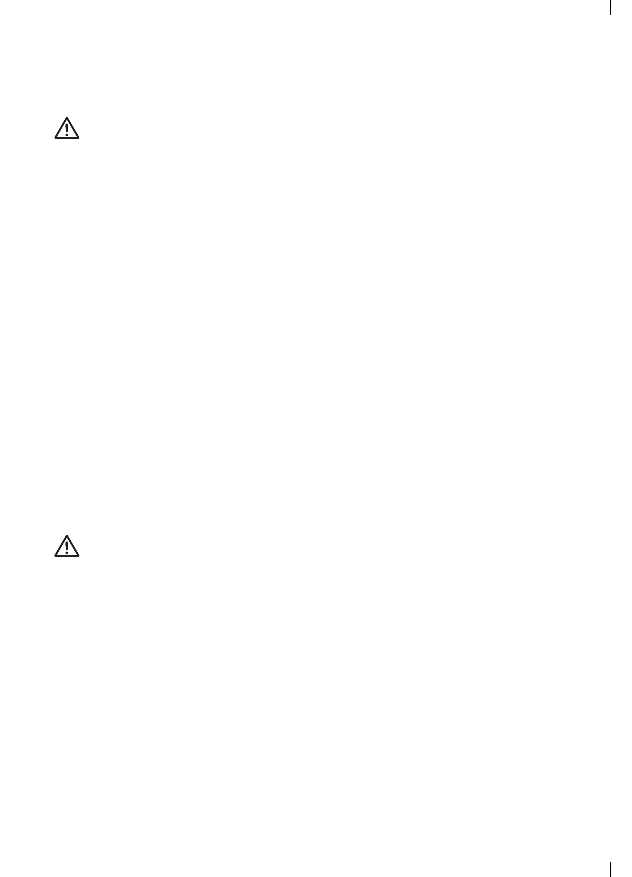
CHANGING THE OVEN LAMP INSIDE THE OVEN (g. 7 - page 10)
Unscrew the protective protruding cap inside the oven (A). Unscrew and change the bulb (B) with a new one with the same power and resistance to high
temperatures (300°C). Put the cap back in place by screwing it in clockwise.
OVEN DOOR REMOVAL
DOOR WITH TRADITIONAL HINGE
• Lift levers B and hold the door by its two sides with both hands, near hinges A.
• Lift the door upwards at an angle of approx. 45° and carefully pull it out. To re-assemble it, t the hinges into the relative grooves, then let the door slide
downwards, and release levers B.
DOOR WITH COMPACT HINGE (g. 9 - page 10)
• Lift levers “2” up to the ledge with hinges “1” and hold the door by its two sides with both hands, near the hinges.
• Lift the door upwards at an angle of approx. 45° and carefully pull it out.
• To re-assemble it, t hinge “2” into the relative grooves, then let the door slide downwards, making sure it stays blocked in the grooves “3”, then release
levers “1”.
REMOVING THE GLASS FROM THE OVEN DOOR (only in applicable models)
This operation can only be carried out when the appliance is cold.
To take the glass out from the oven door, you must do the following:
• Open the door slightly.
• Press the black keys located on the side supports of the door at the same time, and slide them upwards.
• Remove the top prole of the door.
• Take the glass out by pulling it towards you.
To re-install the glass, follow these steps in reverse order being careful to align the glass with the side supports and making sure that the letters VIT are in
the bottom right corner marked by the arrow. Lastly, put the top prole back in place on the door.
(g. 8 - page 10)
9
g.7 g.8 g.9
CHANGING THE POWER CABLE (this operation must be carried out exclusively
by qualied personnel)
Disconnect the appliance from the power mains and take the rear panel off
the cooker to have access to the terminal board (g. 10). Loosen the clamping
screws of the cable retainer and the screws on the terminal board that hold down
the three cable conductors (g. 11).
the instructions listed below:
• Blue cable for Neutral on clamp N;
• Brown cable for Phase on clamp L;
• Yellow-Green cable for earth on clamp.
Attach the cable to the corresponding cable clamp (brown terminal board) and
re-assemble the rear panel of the cooker.
If the power cord is damaged, contact immediately the after sales service which will replace it.
INSTRUCTIONS FOR THE INSTALLER
g.10 g.11
PRODUCT HANDLING
The product must be handled by two people.
Do not lift the cooker by the oven door handle,
rather, open the door and hold the cooker by the
top of the internal cavity.
Do not drag or make the cooker slide.
INSTALLATION
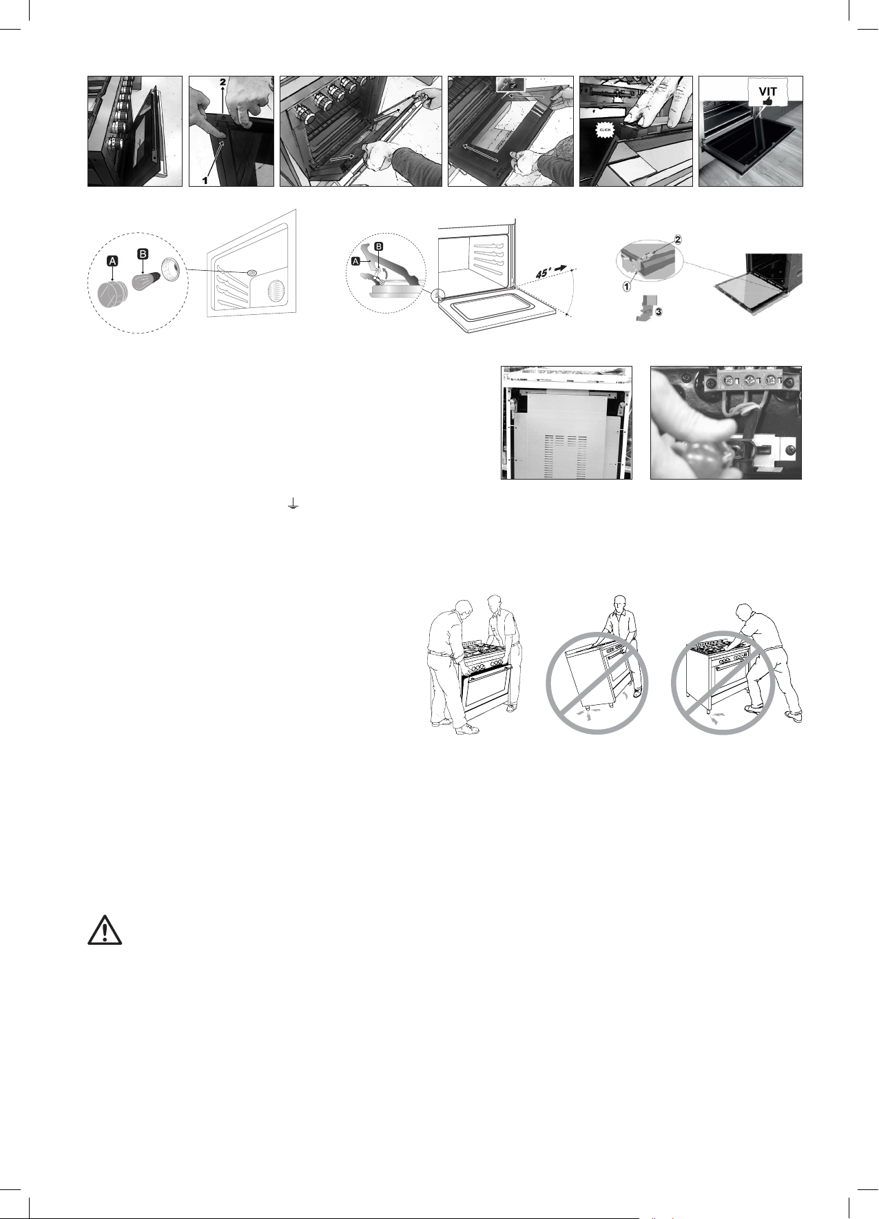
VENTILATION OF THE ROOMS (g. 12 - page 11)
This appliance can only be installed and made to operate in permanently ventilated rooms, in accordance with national legislation in force.
It is essential that the amount of air required for gas combustion can ow through the room where the appliance is installed.
In particular, the air ow required for the correct combustion must not be lower than 2 m
data plate attached to the appliance, applied inside the door under the oven door or on the rear of the appliance).
The air must be drawn directly from the outside through permanent openings or ventilation ducts.
COMBUSTION GAS EXHAUST (g. 13 - page 11)
WARNING
It is essential that all operations relative to installation, regulation and technical maintenance are carried out exclusively by qualied personnel.
The appliance must be installed in compliance with regulations in the country of use.
This appliance is not connected to an exhaust device for the combustion products. The appliance must convey the combustion products out into the atmosphere
through a specic hood connected to a stack, ue or directly outdoors.
Intense or prolonged use of the appliance may require supplementary ventilation, for example, the opening of a window, or more effective ventilation by increasing
the level of mechanical ventilation, when applicable.
3
/h for every kW of the appliance's rated power. (Refer to the technical
INSTALLATION (g. 14 - page 11)
The appliance is class 1 and class 2.1 (see reference gure below). It can be free-standing or recessed (installed between other elements) in observance of the
following minimum distances: 750 mm between the hob and any horizontal element above it (cabinets, for example); this space can be reduced to 650 mm if
the above element is an extraction hood; 150 mm between the side of the appliance and elements that are taller than the appliance. It can be installed alongside
walls that are higher then the work surface, at a minimum distance of 150 mm from the side of the appliance.
If it is installed between elements, it is necessary that the furniture of these elements be resistant to temperatures of up to 90 °C.
10
Appliances with a cylinder cabinet and electric oven can only be installed as free-standing
A
ventilation opening for air ow
required for correct combustion
min. 750 mm
min. 150 mm
g.12
enlarged hole to allow
adequate air ow from the adjacent room
min. 750 mm
g.14
direct exhaust out-take to the
outdoors
min. 750 mm
min. 150 mm
g.13
exhaust out-take through the ue
installed for the cooker only
Recessed appliance
(Class 2 sub-class 1)
Recessed appliance
(Class 2 sub-class 1)
Free-standing appliance
installation (Class 1)
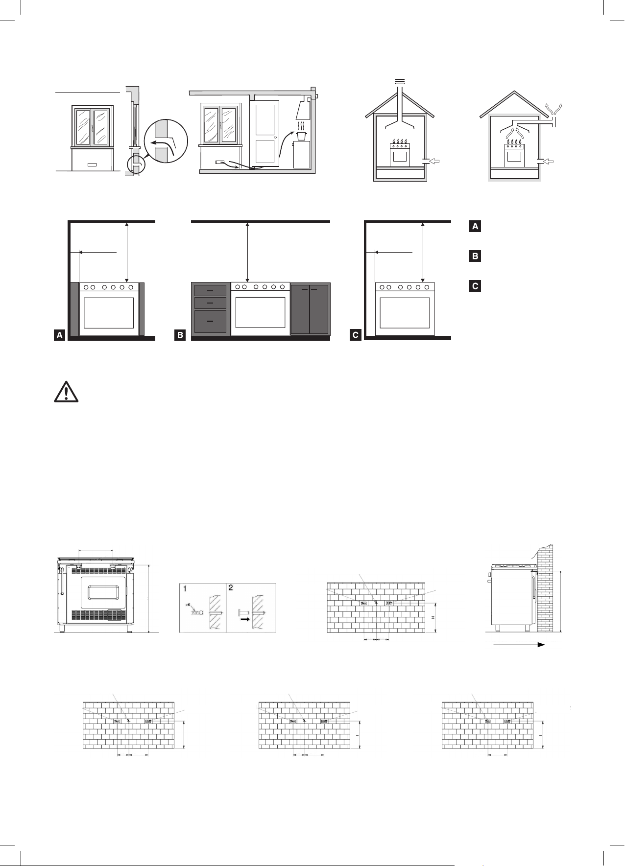
STABILITY DEVICE (only if required by regulation in the country of use and provided as a kit together with the cooker)
WARNING
To prevent accidental tipping of the appliance, it is necessary to install this stabilizing device as shown in the pictures below.
1. Children should not play or sit, on the open oven door.
2. Do not lean or sit, on the appliance’s open door. The excessive load may compromise the stability.
3. Do not place hot pans with sharp bottom, on the internal glass.
For models with a width of 50, 60, 70, 80, 90, 100 cm it is necessary to install rear safety devices, as an absolute guarantee against the appliance tipping
forwards, even when bearing heavy loads on the open oven door.
• There is a rear cover panel installed on the rear of the cooker. Measure distance H from the highest point of the panel to the oor (A).
• Use the value of the H measurement to draw reference marks where the holes for the plugs will need to be drilled on the wall where the cooker will be
installed (B).
• Also mark the centre distance of the cooker on the wall at the same previously measured H height (C).
• It is now possible to install the two brackets at a distance of 400 mm from each other (200 mm from the centre distance) and position the cooker against
the wall under the two brackets (D).
400 mm
CENTRE DISTANCE OF COOKER
BRACKET 1
H
200 mm 200 mm
BRACKET 2
H
A B C D
If your cooker has a 90x60, 80x50 cylinder cabinet, or 80x50 cabinet, it is necessary to assemble the brackets at the distance given in the pictures below:
CENTRE DISTANCE OF COOKER CENTRE DISTANCE OF COOKER CENTRE DISTANCE OF COOKER
BRACKET 1
200 mm 315/320 mm
Cooker with 90 x 60 cylinder cabinet Cooker with 80 x 50 cylinder cabinet Cooker with 80 x 50 cabinet
BRACKET 2
H
BRACKET 1
BRACKET 2
H
200 mm 310 mm
BRACKET 1
280 mm
LEVELLING
Once the supplied feet are tted and screwed in, if necessary, level the appliance by turning them. This will avoid any possible oscillation.
BRACKET 2
H
11
CONNECTION
GAS CONNECTION
While the connection to the gas mains or gas cylinder can be made with various types of tubes (exible rubber or steel), it is nevertheless necessary to carry out
this operation in accordance with regulations and amendments in force, once it has been ascertained that the appliance is properly adjusted to the type of gas it
will be supplied with (see technical plate inside the bottom door or on the rear of the cooker).
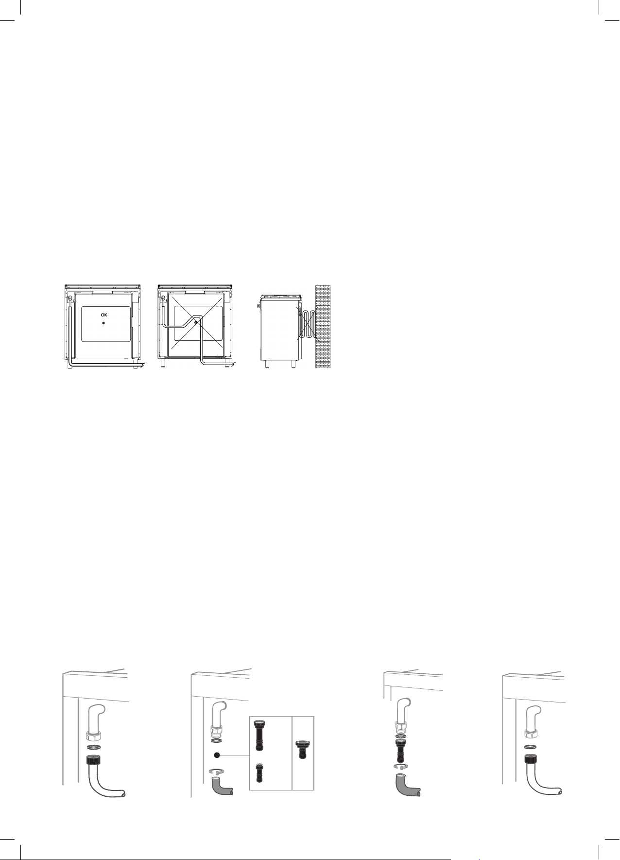
CONNECTION WITH FLEXIBLE METAL TUBE (g. 15)
The connection is made using a tube that is compliant with national regulation, connected to the appliance threaded tting, through the use of a sealing joint
(gasket). The maximum extension of the tube must not exceed 2 metres in length.
CONNECTION WITH FLEXIBLE RUBBER TUBE
• This type of connection is not authorized when the appliance is recessed (class 2/1 appliance) and the tube can not be inspected for its entire length. Connect
the tube connection to the threaded tting through the use of a sealing joint (washer).
Depending on the type of gas being used, the tubes will have different diameters:
• G30 (GPL) gas tube (g. 16) to be applied to tube connections with an 8 mm diameter;
• G20 (METHANE) gas tube (g. 17) to be applied to tube connections with a 12 mm diameter.
Fasten the two ends of the tube with the required tube clamps according to national regulations.
The tube must be replaced by the terms of the date printed on it and must not exceed the maximum length of 1.5 metres.
• The tube must not come into contact with: sharp objects, corners and with the cooker rear panel (see picture A); it must not be strained or twisted; no point
of the tube must exceed a temperature of 50°C.
g. A
g. Cg. B
If the gas pipe is damaged, do not attempt to repair it by yourself but replace it with a new one before using the appliance.
GAS CONNECTION TO THE CYLINDER
With models with a cylinder cabinet it is possible to house cylinders with up to 15 kg of butane, that are compliant with national regulations.
The cylinder must be equipped with a pressure reducer, compliant with national regulations.
The connection to the cylinder must be set up in compliance with installation standards pursuant to national regulations.
The exible tube used for the connection must have an internal diameter of 8 mm, it must be compliant with standards and must be replaced before its expiration
date. It must be tted to the tube connection on the cooker and the pressure reducer using regulation tube clamps.
During the operations to connect the cylinder, it is necessary to follow the instructions below:
• the gas connecting tube must not exceed 1 meter in length;
• the pressure reducer tting must face the door of the cylinder cabinet;
• the route of the exible tube must not touch any hot surfaces of the cooker (the left inside wall of the cylinder cabinet, the rear of the cooker and cabinet ceiling)
and IT MUST follow the route provided by the relative clamps;
• the cylinder must be set up so that it is not touching the wall adjacent to the oven.
Whenever you nish cooking, it is advisable to close the cylinder valve.
CONNECTION WITH RIGID COPPER PIPE
(g. 18)
Connect the rigid part to the threaded tting located on the rear side of the appliance, through a regulation sealing joint.
SEAL CHECK
Following installation, make sure the ttings are rmly connected. Never use a ame to check the seal on the gas circuits, always use a soapy solution.
ELECTRICAL CONNECTION
Install a plug on the cable, suitable for the load stated on the specications plate on the appliance (located inside the door under the over door, or on the rear of
the cooker). The electrical connection must have an efcient earthing connection. The yellow-green conductor for the power cable must not have any switches
g.15 g.16 g.17 g.18
12
set up along it. When there is a direct connection to the mains, it is necessary to set up a omnipolar switch between the appliance and the mains with a
minimum opening between the contacts of 3 mm, sized for the load and compliant with national standards in force (the earth wire must not have any switches
set up along it). The power cable must be positioned so that it does not exceed the ambient temperature by 50°C at any point.
The manufacturing company will not be held liable in cases of failure to observe the electrical regulations in force, and if the connection has not been set up
by qualied personnel.
ADAPTATION TO THE DIFFERENT TYPES OF GAS
WARNING
The appliance is designed to operate with different types of gas; each type of gas requires specic injectors and adjustments. To make any
variations it is always necessary to cut the appliance off from the power mains and temporarily cut off the gas supply from the mains.
CHANGING HOB BURNER INJECTORS (g. 19)
Manually remove the burners (no other disassembly operation is required) and using a suitable socket wrench, unscrew the injectors and replace them with the
ones suitable for the type of gas, as listed in the technical data table and in the data plate on the cooker (see gure at the top of page 12).
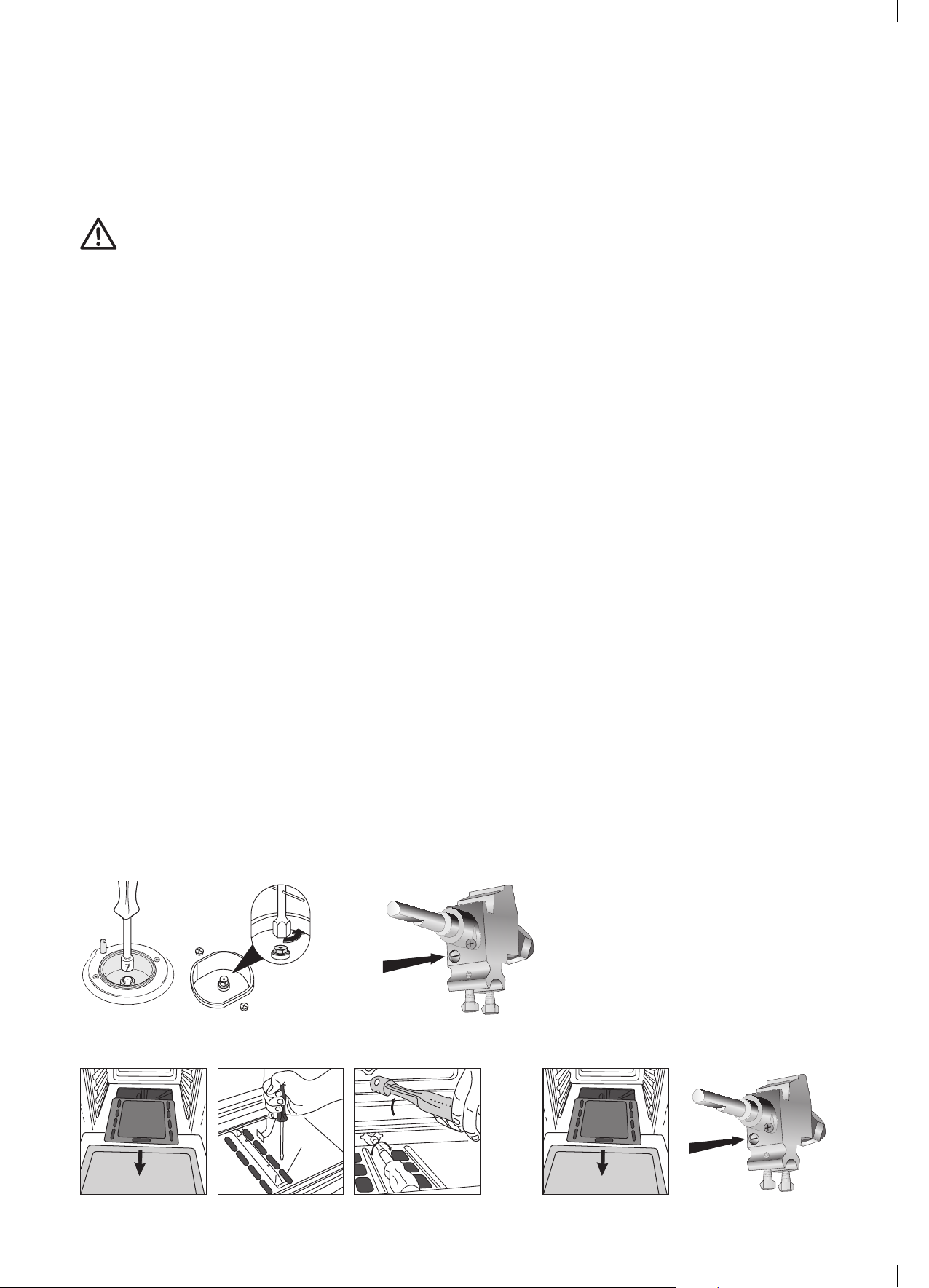
REGULATING THE MINIMUM FLOW LEVEL OF GAS TO THE HOB BURNERS (g. 20)
The regulation of the minimum ow rate of gas to the burners is carried out in factory. When an injector is changed to adapt it to the type of gas available, or
following particular pressure conditions of the mains, it may be necessary to regulate the minimum again. Ignite the burner and let it operate on maximum
capacity for approximately 10 minutes. Rotate the knob to the minimum position. Remove the knob by pulling it off the valve rod. With a small at head screwdriver
adjust the minimum by turning the by-pass screw clockwise to decrease the ame or counter-clockwise to increase the ame. When using valve cocks the
adjustment screw (by-pass) is located on the body of the cock. When using valves other than valve cocks, the adjustment screw is situated inside the valve body.
After any injectors replacement or adjustment operation always make sure that the ame is blue, steady and quiet and produces no detachment from the burner
and will not cause backre between the passage from maximum to minimum.
CHANGING BURNER INJECTORS INSIDE THE OVEN (g. 21)
Take the burners out by removing the clamping screws and using a suitable wrench to unscrew the injectors and replace them with the ones that are suitable for
the type of gas, as listed in the technical data table.
REGULATING PRIMARY BURNER AIR INSIDE THE OVEN (only applicable to models with tube burners)
Some models have a metal collar (xed with screw) located on the end of the burner to adjust the air opening (by increasing or decreasing the amount of air) based
on the result you wish to obtain. After any injector adjustment operation always make sure that the ame is blue, steady and quiet and produces no detachment
from the back burner and will not cause backre between the passage from maximum to minimum.
REGULATING THE MINIMUM FLOW RATE OF GAS TO THE OVEN AND GRILL BURNERS (g. 22)
Turn the burner on and position the knob on the maximum temperature. Let the oven heat up for at least 30 minutes. Rotate the knob to the minimum position.
Pull the knob out of the thermostat rod and with a small at head screwdriver adjust the minimum by turning the by-pass screw clockwise to decrease the ame
or counter-clockwise to increase the ame. The ame should be short and steady; no air drafts or the closing of the door have to cause the extinguishing of the
ame or its return. The adjusting screw (by-pass) is usually located on the body of the thermostat. When using valve cocks the adjustment screw (by-pass) is
situated on the body of the cock (g. 23). When using valves other than valve cocks, the adjustment screw is situated inside the valve body.
After any action to change or adjust parts of the appliance, it is necessary to carefully re-assemble all affected parts to restore the original features. Any
adaptations made for a different type of gas must be completed by changing the tube connection. In this case, also check the circuit seal with a soapy solution,
and never with the use of a ame. Lastly, replace the old calibration label with a new one (included) for the new type of gas being used.
Your product is now correctly installed. Please remove all information labels and materials (located inside the oven) before turning it on.
g.19 g.20
g.21 g.22
13
TECHNICAL ASSISTANCE
To nd an authorized service center near you, contact your dealer. We recommend having the information available on your technical data plate.
PRODUCT AND PACKAGING DISPOSAL
The packaging used on our products can be recycled, therefore we ask you not to dispose of the packaging or parts of it as household
waste, and to dispose of it in the best way possible to reduce the effect on the environment.
If you are purchasing our appliance to replace an old one, it is necessary to contact your locally authorized company for the collection of
decommissioned appliances. This will allow the recyclable materials to be re-used and avoid polluting the environment.
The crossed-out bin symbol printed on the appliance indicates that at the end of its service life the appliance must be collected
separately from other waste. Accordingly, at the end of its service life, the user must hand the appliance over to suitable electric and
electronic waste collection centres, or deliver it to the dealer when purchasing a new, similar appliance, on a one for one basis. The
suitable dismantling of the decommissioned appliance and sending of its parts to recycling, ecologically compatible treatment and
disposal, contributes to avoiding possible negative effects on the environment and human health and promote the re-use of the materials
that comprise the appliance. The unlawful disposal of the product by the user will result in administrative sanctions.
* In reference conditions, gas temperature 15°C, atmospheric pressure 1013.25 mbar
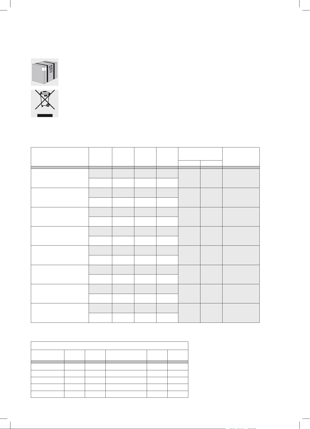
TECHNICAL DATA
BURNER TYPE
(sizes mm)
MINI AUXILIARY
Ø 39
AUXILIARY
Ø 55
SEMIRAPID
Ø 75
RAPID
Ø 100
ULTRARAPID
Ø 120
FISH BURNER
60x235
TRIPLE
Ø 130
GAS TYPE
LPG 30 46 58 g/h
natural gas 20 68 95 dm
LPG 28..30/37 52 73 g/h
natural gas 20 72 95 dm
LPG 28..30/37 68 127 g/h
natural gas 20 98 167 dm
LPG 28..30/37 88 218 g/h
natural gas 20 116 286 dm
LPG 28..30/37 91 240 g/h
natural gas 20 124 314 dm
LPG 28..30/37 88 211 g/h
natural gas 20 120 276 dm
LPG 28..30/37 96 262 g/h
natural gas 20 135 343 dm
PRESSURE
(mbar)
INJECTOR
MARKING
(1/100 mm)
GAS
CONSUMPTION*
POWER (kW)
MAX. MIN.
3
/h
3
/h
3
3
3
3
3
0,800 0,300
1,000 0,300
1,750 0,440 16÷20
/h
3,000 0,750 20÷24
/h
3,300 1,500 22÷26
/h
2,900 1,500
/h
3,600 1,500 24÷28
/h
RECOMMENDED
POT
DIAMETER**
(cm)
12÷14
6 with reduction
grill
12÷14
6 with reduction
grill
Max
14÷35
TRIPLE
Ø 130
* In reference conditions, gas temperature 15°C, atmospheric pressure 1013.25 mbar. ** In compliance with burners and pots specications.
LPG 28..30/37 98 277g/h
natural gas 20 137 363 dm
3
3,800 1,500 24÷28
/h
POWER OF HEATING ELEMENTS
COOK-TOP
Diameter
(mm)
Electric plate Normal 145 1000 Circular High-Light 145 1200
Electric plate Normal 145 1500 Circular High-Light 180 1800
Electric plate Rapid 180 2000 Circular High-Light 210 2200
14
Power
(Watts)
Diameter
(mm)
Extensible High-Light 120/210 700/2100
Extensible High-Light 170/265 1400/2200
Power
(Watts)
OVEN CAPACITY
(Liters)
Bottom
Element
(Watts)
OVEN
Top Element
(Watts)
Grill Element
(Watts)
Double-Grill
Element
(Watts)
Circular
Element
(Watts)
Storage
Compartment
Element
(Watts)
123 1500 950 2000 2950 / /
111 1500 950 1500 2450 2400 /
105 1500 950 2000 2950 / /
95 1500 950 1500 2450 2400 /
90 1500 950 2000 2950 / /
80 1500 950 1500 2450 2400 /
67 1400 850 1400 2250 / /
61 1400 850 1400 2250 2200 /
61 Double Oven 1100 700 1400 2100 2200 500
58 1100 650 1350 2000 / /
51 1100 650 1350 2000 2200 /
47 900 600 1350 1950 / /
37 Double Oven 800 500 1200 1700 / 500
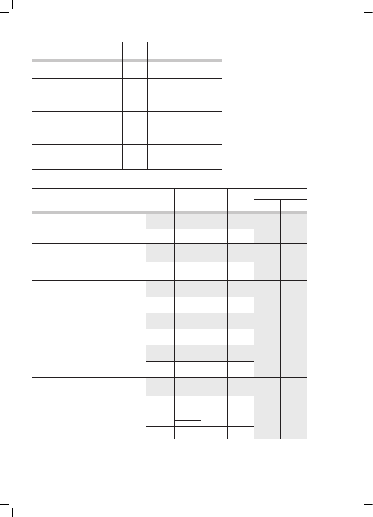
TECHNICAL DATA
VOLUME OVEN / BURNER GAS TYPE
Oven burner
Volume cavity: 37 – 41 l (dm
3
)
LPG 28..30/37 62 145 g/h
Small oven/double oven cooker
Cooker dimensions (WxD): 90x60 or 100x60
Oven burner
Volume cavity: 45 – 70 l (dm
3
)
Single oven cooker
natural gas 20 108 190 dm
LPG 28..30/37 79 193 g/h
Cooker dimensions (WxD): 50x50, 60x50, 70x50, 60x60,
Bottle compartment 80x50, Bottle compartment 90x60
Big oven/double oven cooker
natural gas 20 122 252 dm
Cooker dimensions (WxD): 90x60 or 100x60
Oven burner
Volume cavity: 74 – 109 l (dm
3
)
LPG 28..30/37 93 276 g/h
Single oven cooker
Cooker dimensions (WxD): 80x50 or 80x60
Oven burner
Volume cavity: 102 – 126 l (dm
3
)
natural gas 20 145 362 dm
LPG 28..30/37 100 305 g/h
Single oven cooker
Cooker dimensions (WxD): 90x60 or 100x60
Grill burner
Volume cavity: 37 – 41 l (dm
3
)
natural gas 20 150 400 dm
LPG 28..30/37 60 116 g/h
Small oven/double oven cooker
Cooker dimensions (WxD): 90x60 o 100x60
natural gas 20 101 152 dm
PRESSURE
(mbar)
INJECTOR
MARKING
(1/100 mm)
GAS
CONSUMPTION*
3
/h
3
/h
3
/h
3
/h
3
/h
POWER (kW)
MAX. MIN.
2,000 0,700
2,650 1,000
3,800 1,000
4,200 1,000
1,600
Grill burner
Volume cavity: 45 – 70 l (dm
Single oven cooker
3
)
LPG 28..30/37 65 145 g/h
Cooker dimensions (WxD): 50x50, 60x50, 70x50, 60x60,
Bottle compartment 80x50, Bottle compartment 90x60
Big oven/double oven cooker
natural gas 20 108 190 dm
3
/h
Cooker dimensions (WxD): 90x60 o 100x60
3
GRILL (dm
80/123)
85-86/96-16 (large oven and giant oven)
Liquid gas
28..30/37
3,0 (kPa)
Natural gas 20 120 252 dm3/h
80 192 g/h
* In reference conditions, gas temperature 15°C, atmospheric pressure 1013.25 mbar. ** In compliance with burners and pots specications.
2,000
2,600
15

COOKING TABLE
DISH
STATIC OVEN (no fan)
ELECTRIC OR GAS
cooking level
inside rack
temperature °C
VENTILATED OVEN
(multi level cooking)
cooking level
inside rack
COOKING
TIME
temperature °C minutes
Desserts
Shortcrust pastry 3 190-200 2 (1-3) 180-190 30-35
Mixed-dough cake 2 200-210 2 (1-3) 190-200 30-35
Pie 2 190-200 2 (1-3) 180-190 30-35
Plum cake 3 190-200 2 (1-3) 180-190 30-35
Fruit cake 3 175-190 2 (1-3) 165-180 35-45
Nut cake 3 190-200 2 (1-3) 180-190 40-45
Strudel 2 195-200 2 (1-3) 185-195 35-45
Sponge cake 2 195-210 2 (1-3) 185 35-45
Cream Caramel 3 130-150 2 (1-3) 130 30-35
Chocolate cake 2 180-190 2 (1-3) 180 35-40
Croissants 2 190-200 2 (1-3) 180-190 25-30
Cookies 2 180 2 (1-3) 165 20
Pastries 3 230-250 2 (1-3) 200-230 10-15
Scones 1 190-210 1 (1-2) 180-190 20
Mufns 3 205-220 2 (1-3) 185-200 25-35
Bread and pizza
Pizza 2 215-230 2 (1-3) 195-210 20-30
Focaccia 2 220 2 (1-3) 190-210 20-30
Bread 3 235-250 3 (2-3) 215-230 40-50
Main courses
Lasagna 3 185-200 2 (2-4) 165-180 30-40
Baked pasta 3 190-200 2 (2-4) 180-190 35-45
Vegetable ans 2 180-190 2 (1-3) 170-180 30-40
Roasted meat
1 Kg beef 2 220-225 2 (1-3) 200-220 50-60
1 Kg lamb 2 190-220 2 (1-3) 180-200 50-60
1 Kg veal 2 190-220 2 (1-3) 180-200 60-70
Chicken 2 205-215 2 (1-3) 195-210 40
Duck 2 210-220 2 (1-3) 195-210 120-180
Goose 2 210-220 2 (1-3) 195-210 120
Turkey 2 215-230 2 (1-3) 195-210 120
Rabbit meat 2 215-235 2 (1-3) 200-200 40
Pheasant 2 205-215 2 (1-3) 195-210 40-50
Fish
Fillets and slices 2 170-180 2 (1-3) 160-170 20-30
Roasted meat 2 190-200 2 (1-3) 180-190 25-35
Baked in tin foil 2 200-210 2 (1-3) 190-200 25-35
Cooking notes
The data provided here must be considered a guideline. Therefore, it can and must be changed based on your own tastes and habits.
The time reported in the table does not include the pre-heating function, which is always recommended.
The time and temperature provided refer to an average amount of food: 1/1.5 kg for meat, pastry/pizza/bread dough 0.5/0.8 Kg.
Multiple cooking on several levels must be carried out by putting the containers in the centre of each rack.
GRILLING TABLE
DISH
cooking level
inside rack
temperature °C
Toast 3-4 200 3-4
Hamburgers 3-4 200 5-7
Fish skewers 3-4 200 6-8
Shellsh 3-4 200 6-8
Sausages 3-4 200 7-10
Ribs 3-4 200 7-10
Meat skewers 3-4 200 8-10
Steaks 3-4 200 8-12
Chicken 3-4 200 30-35
Grilling notes:
• 5-10 minutes pre-heating is enough for recipes that require it.
• The stated amount of time refers to only one side of the dish, it is therefore necessary to turn it.
• Put a baking tray on the rack below with a cup of water in it (0.2 l) to limit grease drops and excessive smoke during cooking.
16
cooking time
minutes

Français - FR
17

Nous vous remercions vivement d'avoir choisi notre produit
qui répondra sûrement à vos besoins. Nous vous prions donc
de bien vouloir lire attentivement et conserver ce manuel
contenant des informations importantes et des conseils utiles
pour une utilisation optimale et en toute sécurité de votre
nouvelle cuisinière.
Cet appareil est conforme avec:
- 2006/95/CE Basse Tension (Directive)
- 2004/108/CE Compatibilité Electromagnétique (Directive)
- 2009/142 Appareils à gaz (Directive)
- 1935/2004/CE Matériaux destinés à entres en contact avec
des denrées alimentaires (Règlement)
- 2002/95/CE Limitation de l’utilisation de certaines substances
dangereuses dans les équipements électriques et électroniques
(Directive)
- 2002/40/CE L’étiquetage énergétique des fours domestiques
électriques (Directive)
SOMMAIRE
19 Mises en garde générales
21 Votre produit
21 Utilisation
Plan de cuisson
Four
Programmateurs et minuteurs
Conseils de cuisson
25 Nettoyage
25 Maintenance
26 Instructions pour l'installateur
Manutention du produit
Installation
Adaptation aux différents types de gaz
30 Données techniques
30 Assistance technique
30 Élimination du produit et de l'emballage
32 Tableau de cuisson
18

MISES EN GARDE GÉNÉRALES
Cet appareil a été conçu et fabriqué pour un usage exclusivement
domestique. Tout autre usage (pour le chauffage par exemple) est
considéré impropre et donc très dangereux.
Les enfants âgés de moins de 8 ans ne doivent pas s’approcher à moins
qu’ils soient continuellement surveillés. Cet appareil n’est pas destiné à
être utilisé par des enfants ou des personnes dont les capacités physiques,
sensorielles ou intellectuelles sont réduites, ou par des personnes
manquant d’expérience ou de connaissances, à moins que celles-ci ne
soient sous surveillance ou qu’elles aient reçu des instructions quant à
l’utilisation de l’appareil par une personne responsable de leur sécurité
qui puisse leur assurer une utilisation de l’appareil sans danger.
Veillez à ce que les enfants ne puissent pas jouer avec l’appareil qu’il soit
en marche ou éteint. Il est interdit de confier le nettoyage de l'appareil
aux enfants.
En cas de panne ou de dysfonctionnements de l'appareil, nous vous
prions de bien vouloir fermer le robinet à gaz, débrancher l'appareil et
ne pas entreprendre soi-même la maintenance. Contacter directement
le centre d'assistance agréé le plus proche (voir la section «assistance
technique» de cette notice).
Les températures superficielles de tous les composants respectent
rigoureusement les normes en vigueur. De toute façon faire très attention
à certaines parties en métal qui pourraient brûler pendant ou après
l'utilisation.
La cuisinière ne peut pas être installée sans les pieds;
La société décline toute responsabilité en cas de non-respect des
indications contenues dans cette notice d’utilisation.
La société se réserve le droit de modifier les caractéristiques techniques
des produits en respectant toutefois la sécurité et la fonctionnalité.
19

ATTENTION
Certaines parties de la cuisinière sont protégées par un film spécial. Avant de mettre l'appareil en marche, l'enlever, puis
utiliser de l'eau tiède savonneuse pour éliminer les éventuels résidus collants.
Prévention contre les accidents domestiques.
Ne pas laisser l'appareil sans surveillance lors de la cuisson d'huiles ou de graisses; cela peut être la source d'un incendie.
Ne pas laisser d'objets à proximité des surfaces de cuisson.
Si le plan de cuisson est en vitrocéremique et, si la surface est fêlée, éteindre l'appareil pour éviter des possibles charges électriques.
Ne JAMAIS essayer d'éteindre une flamme ou un incendie avec de l'eau, mais éteindre plutôt l'appareil et couvrir la flamme avec
un couvercle ou une couverture ignifuge.
Éviter que les marmites débordent du plan de cuisson durant l'utilisation. Nous recommandons également d'utiliser des
récipients avec fond intact et plat.
Pendant l'utilisation, l'appareil se surchauffe. Les enfants doivent être éloignés de l'appareil. Faire attention et éviter de
toucher les éléments chauds à l'intérieur du four.
Les parties accessibles peuvent être très chaudes lorsque le grill est utilisé; par conséquent, les enfants doivent être tenus à l'écart.
Ne pas utiliser les jets de vapeur pour nettoyer l'appareil. La vapeur pourrait atteindre les parties électriques, les
endommager et causer des courts-circuits.
Ne jamais nettoyer les parties en acier ou traitées superficiellement avec des finitions métalliques (exemple: anodisations,
nickelages, chromages) en utilisant des produits contenant du chlore, de l'ammoniac ou de l'eau de Javel.
Il est fondamental que toutes les opérations relatives à l'installation, le réglage et la maintenance technique soient
effectuées par du personnel qualifié. L'appareil doit être installé conformément aux normes en vigueur dans le pays d'utilisation.
Avant toute opération de maintenance, nous recommandons de débrancher l'appareil de la prise de courant et d'attendre
qu'il soit complètement froid.
Pour éviter le basculement accidentel de l’appareil, installer le dispositif de stabilisation selon les indications de la page
27 de la section installation.
L'appareil est prévu pour le fonctionnement avec plusieurs types de gaz; chaque gaz nécessite des injecteurs et réglages
spécifiques. Pour effectuer les modifications, il est toujours nécessaire de débrancher l'appareil du courant électrique et de
fermer temporairement la distribution du gaz de réseau.
Si votre cuisine est équipée d'un couvercle en cristal, s'assurer qu'il soit ouvert avant l'allumage des brûleurs, pendant le
fonctionnement et les phases de refroidissement qui suivent l'utilisation. Le non-respect de cette indication peut causer la rupture du verre.
Ne pas utiliser de produits abrasifs, de brosses coupantes en métal pour nettoyer la porte en verre du four. Ceci pour éviter
d'égratigner la surface, provoquant ainsi le cassage du verre.
Enlever du couvercle les éventuels liquides débordés avant de l'ouvrir. Faire refroidir la surface du plan de cuisson avant
de fermer le couvercle.
Lors de la première utilisation du four, enlever tous les accessoires et les matériaux fournis placés à l'intérieur de la cavité,
l'allumer, le faire fonctionner à vide pendant au moins 1 heure à la température maximale et avec la porte fermée (sans utiliser la
fonction Gril). Ensuite l'éteindre, ouvrir la porte du four et aérer l'intérieur. L'odeur qui se dégage est due à l'évaporation des
substances de scellage et de protection du four.
L'appareil n'est pas conçu pour fonctionner avec un temporisateur externe ni un système de commande à distance.
L’utilisation d’un appareil à gaz produit de la chaleur et de l’humidité dans la pièce où il est installé. Il faut donc être bien
aéré en gardant claire les orifices naturel de l’air ou en activant un système d’aération mécanique (hotte d’extraction avec tuyau
d’échappement).
Pendant la cuisson, ne pas recouvrir le fond du four ou de la table avec des feuilles d’aluminium.
20

VOTRE PRODUIT
Compte tenu de la large gamme de produits présents sur le marché, cette notice contient des informations relatives à plusieurs modèles; il est donc possible que toutes les
indications qu'il contient ne se réfèrent pas à votre appareil ou à vos accessoires. Nous restons toutefois à votre entière disposition pour tout éclaircissement.
La cuisinière est divisée en plusieurs parties principales:
• plan de cuisson: compartiment contenant les les grilles (support pour les marmites), les brûleurs à gaz (généralement appelés réchauds), 1 plaque électrique ou les zones
vitrocéramiques selon les dimensions et le modèle de la cuisine
• panneau de commande: Contrôle de la cuisinière, zone des dispositifs (c’est à dire des boutons et interrupteurs).
• porte du four
IDENTIFICATION DES SYMBOLES DU PANNEAU DE COMMANDE
SYMBOLE SIGNIFICATION
Brûleur/zone avant gauche
Brûleur/zone arrière gauche
Brûleur central
Brûleur/zone avant droite
Brûleur/zone arrière gauche
Brûleur/zone gauche
Contrôle de la température du four (°C)
Timer/minuteur
SYMBOLE SIGNIFICATION
Fonctions four électrique multifonction
Thermostat four
Brûleur four gaz
Brûleur gril
Touche lumière
Touche allumage (étincelle)
Touche gaz ventilé (MultiChef)
Les deux voyants lumineux indiquent que le four électrique
est en marche ou que le four est en phase de chauffage
UTILISATION
PLAN DE CUISSON
UTILISATION DU PLAN
Si la cuisine est équipée d'un couvercle en cristal, s'assurer qu'il est ouvert avant l'allumage des brûleurs, pendant le fonctionnement et
les phases de refroidissement qui suivent l'utilisation. Le non-respect de cette indication peut causer la rupture du verre.
ALLUMAGE DU BRÛLEUR À GAZ (RÉCHAUD).
Approcher du brûleur une allumette (un générateur d'étincelles ou de amme), appuyer et tourner dans le sens inverse des aiguilles d'une montre la
poignée spécique sur la position de MAX .
Le plan peut être équipé d'allumage électrique qui s'active à l'aide du bouton séparé ou de la pression de la poignée en question.
Après l'allumage, maintenir appuyée la poignée pendant environ 10 secondes, puis la relâcher, régler l'intensité de la amme en prenant soin de positionner
la poignée entre le maximum et le minimum (inclus), jamais entre le maximum et zéro pour éviter les extinctions non voulues.
Il peut arriver que le brûleur s'éteigne au moment du relâchement de la poignée: cela veut dire que le thermocouple ne s'est pas assez chauffé.
Si l'allumage ne se produit pas dans les 15 secondes, attendre au moins 1 minute avant de répéter l'opération.
Si le modèle choisi est sans robinet de sécurité gaz (thermocouple cuivre près du brûleur), contrôler régulièrement pendant l'utilisation qu'il n'y ait pas
d'extinctions accidentelles des ammes dues aux possibles sorties du liquide durant la cuisson.
UTILISATION DES PLAQUES ÉLECTRIQUES
L'allumage des plaques électriques s'effectue en tournant la poignée dans le sens des aiguilles d'une montre, congurant la valeur de 0 à 4.
En augmentant, la valeur numérique correspond à l'augmentation de la puissance électrique utilisée.
Lors du premier allumage d'une plaque ou après une longue période d'inactivité, nous recommandons de la faire fonctionner à vide en position de
«chauffage minimum» (position 1) pendant au moins 15 minutes pour éliminer l'éventuelle humidité absorbée par l'isolation. Pour optimiser l'utilisation
des plaques électriques, utiliser des marmites avec fond plat et éviter l'utilisation des marmites de diamètre inférieur à celle de la plaque.
UTILISATION DU PLAN VITROCÉRAMIQUE (HIGHLIGHT)
Merci de bien vouloir consulter le manuel spécique fourni avec l'appareil.
PRÉVENTION DES ACCIDENTS DOMESTIQUES
Ne pas laisser l'appareil sans surveillance lors de la cuisson d'huiles ou de graisses.
Ne pas laisser d'objets à proximité des surfaces de cuisson.
Lorsque le plan de cuisson est vitrocéramique, si la surface est fêlée, éteindre l'appareil pour éviter des possibles charges électriques.
CONSEILS PRATIQUES POUR L'UTILISATION DU PLAN DE CUISSON
Pour une meilleure performance des brûleurs et une consommation minimale de gaz, nous recommandons d'utiliser des récipients à fond plat, munis de
couvercles et proportionnés au brûleur. Le tableau ci-dessous indique les diamètres des marmites relatifs à chaque brûleur, du plus petit au plus grand.
21

Type (dimension brûleur en cm) Dimension Récipients (cm)
Brûleur auxiliaire (A) Ø 5 Ø 10 - 14**
Brûleur semi-rapide (S) Ø 7,5 Ø 16 - 20
Brûleur rapide (R) Ø 10 Ø 20 - 24
Brûleur triple couronne (TC) Ø 13 Ø 24 - 28
Brûleur poissonnière (PS) 6x23,5 max. 14x35
** La grille de réduction (pour les modèles équipés) doit être utilisée uniquement sur le
brûleur auxiliaire, lors de l'utilisation de récipients ayant un diamètre inférieur à 12 cm.
Type (dimension sérigraphie zone en cm) Dimension Récipients (cm)
Plaque électrique Ø 14,5
Plaque électrique Ø 18
Zone vitrocéramique (highlight) Ø 14,5
Zone vitrocéramique extensible (highlight) Ø 12 - 21
Zone vitrocéramique (highlight) Ø 21
Zone vitrocéramique extensible (highlight) Ø 17 - 26,5 Ø ≥ 17 - 26,5
Ø
Ø
Ø
14,5
18
Ø
14,5
12 - 21
21
Ø
FOUR
ALLUMAGE DU FOUR
Lors de la première utilisation du four, enlever tous les accessoires et les matériaux fournis placés à l'intérieur de la cavité, l'allumer, le faire fonctionner à
vide pendant au moins 1 heure à la température maximale et avec la porte fermée (sans utiliser la fonction Grill). Ensuite l'éteindre, ouvrir la porte du four
et aérer l'intérieur. L'odeur qui se dégage est due à l'évaporation des substances de scellage et de protection du four.
CUISINIÈRE AVEC FOUR À GAZ ET GRIL ÉLECTRIQUE
Le four à gaz est équipé d’un élément de chauffage (brûleur du four) situé sous la base du four et présentant un élément supérieur chauffant (gril).
Certains modèles disposent également d’un ventilateur arrière, qui peut être activé et désactivé par une touche, et est utilisé pour distribuer uniformément
la chaleur pendant l’utilisation. Le contrôle du four s’effectue à l’aide d’un bouton et d’une ou deux touches (
Le brûleur du four doit toujours être allumé avec la porte du four entièrement ouverte et la cavité vide. Appuyez et tournez le bouton du four dans le sens
antihoraire jusqu’à la position MAX
.
En maintenant le bouton vers le bas, approchez une allumette (ou une étincelle ou un générateur de amme) du trou sur la base du four. Maintenez le
bouton enfoncé pendant environ 10 secondes, puis relâchez-le et réglez-le à la température requise. Fermez la porte du four et attendez quelques minutes
pour préchauffer la cavité avant de cuire les aliments.
Certains modèles disposent également d’un ventilateur arrière qui est utilisé pour distribuer uniformément la chaleur pendant l’utilisation du four.
Si vous souhaitez effectuer la cuisson avec de l’air forcé, insérez son contrôle.
Si le brûleur ne s’allume pas dans les 15 secondes, attendez 1 minute avant de réessayer.
Dans certains modèles, le brûleur peut être équipé d’un allumage activé par un bouton séparé ou en appuyant sur le bouton lui-même.
Quand il est allumé, maintenez le bouton enfoncé pendant environ 15 secondes. Le brûleur pourrait s’éteindre lorsque vous relâchez le bouton : cela signie
que le thermocouple n’est pas assez chaud. Attendez au moins 1 minute et répétez l’opération en maintenant le bouton enfoncé plus longtemps.
GRILL ÉLECTRIQUE
La fonction de gril s’active et se désactive à l’aide de sa touche. Pour les cuisinières avec un accessoire pour protéger les boutons (vitrage noir de protection
des boutons), la fonction gril doit avoir lieu avec la porte du four entrouverte. Avant d’activer le gril, xez la protection des bouton sur les fentes situées sur
les deux côtés de la partie frontale, entre le panneau de commande et le four lui-même. Si votre four n’est pas équipé de cet accessoire, cela signie que
la fonction gril doit avoir lieu avec la porte fermée.
Si la cuisinière n’est pas équipée de cet accessoire, alors la grillade doit être effectuée avec la porte fermée.
/ ).
CUISINIÈRE AVEC FOUR ET GRIL À GAZ
Ce type de cuisinière est équipé d’un brûleur situé sous la base du four et d’un brûleur de gril sur le plafond du four.
Le contrôle du four s’effectue en général par un seul bouton
Certains modèles disposent de deux boutons séparés
.
, un pour chaque brûleur, ce qui permet d’utiliser les deux brûleurs à l’intérieur du four en même
temps. Cette option particulière, traditionnellement proposée dans certains marchés, est utile pour la cuisson de grandes quantités de nourriture et pour
porter rapidement le four à la température requise.
FOUR À GAZ
Le brûleur du four doit toujours être allumé avec la porte du four entièrement ouverte et la cavité vide. Appuyez et tournez le bouton du four dans le sens
antihoraire jusqu’à la position MAX.En maintenant le bouton vers le bas, approchez une allumette (ou une étincelle ou un générateur de amme) du trou
sur la base du four. Maintenez le bouton enfoncé pendant environ 10 secondes, puis relâchez-le et réglez-le à la température requise. Fermez la porte du
four et attendez quelques minutes avant de préchauffer la cavité, ensuite mettez les aliments dans le four au niveau désiré.
Certains modèles disposent également d’un ventilateur arrière qui est utilisé pour distribuer uniformément la chaleur pendant l’utilisation du four.
Si vous souhaitez effectuer la cuisson avec de l’air forcé, insérez son contrôle.
GRIL À GAZ (porte du four fermée)
Le brûleur du gril doit toujours être allumé avec la porte du four entièrement ouverte et la cavité vide. Appuyez et tournez le bouton du four dans le sens
antihoraire jusqu’à la position MAX.
En maintenant le bouton vers le bas, approchez une allumette (ou une étincelle ou un générateur de amme) du trou sur la base du four. Maintenez le
bouton enfoncé pendant environ 10 secondes, puis relâchez-le et réglez-le à la température requise. Fermez la porte du four et attendez quelques minutes
avant de préchauffer la cavité, ensuite mettez les aliments dans le four au niveau désiré.
Certains modèles disposent également d’un ventilateur arrière qui est utilisé pour distribuer uniformément la chaleur pendant l’utilisation du four.
Si vous souhaitez effectuer la cuisson avec de l’air forcé, insérez son contrôle.
FOUR À GAZ AVEC GRIL À GAZ (porte du four fermée)
Le brûleur du four doit toujours être allumé avec la porte du four entièrement ouverte et la cavité vide. Appuyez et tournez le bouton du four dans le sens
antihoraire jusqu’à la position MAX.
En maintenant le bouton vers le bas, approchez une allumette (ou une étincelle ou un générateur de amme) du trou sur la base du four. Maintenez le
bouton enfoncé pendant environ 10 secondes, puis relâchez-le et réglez-le à la température requise. Fermez la porte du four et attendez quelques minutes
avant de préchauffer la cavité, ensuite introduisez les aliments dans le four au niveau désiré et allumez le gril à gaz.
Certains modèles disposent également d’un ventilateur arrière qui est utilisé pour distribuer uniformément la chaleur pendant l’utilisation du four.
Si vous souhaitez effectuer la cuisson avec de l’air forcé, insérez son contrôle.
22

CUISINIÈRE AVEC FOUR ÉLECTRIQUE
Notre gamme de fours électriques est divisée en statiques (sans ventilateur) et multifonction. Les statiques ont une seule poignée de commande qui gère les
fonctions et la température interne, alors que les multifonctions en ont deux: l’une pour la sélection des fonctions et l’autre pour la gestion de la température.
FOUR ÉLECTRIQUE AVEC 1 POIGNÉE (STATIQUE - SANS VENTILATEUR) POUR CONTRÔLER LE FOUR
Tourner la poignée dans le sens des aiguilles d'une montre, puis congurer la température souhaitée; les deux lumières du panneau de commande
s'allument pour indiquer que le four est en marche et se réchauffe. Dès que la température congurée est atteinte, le voyant s'éteint.
Dans ces modèles, le Grill est activé en tournant dans le sens des aiguilles d'une montre la poignée jusqu'à actionner le 3e déclic. L'utilisation du grill
(résistance électrique) doit se faire avec la porte du four partiellement ouverte. Dans ce cas, il est indispensable d'appliquer un dispositif de protection des
poignées (pare-chaleur émaillé noir) fourni en équipement standard avec la cuisinière (il se trouve à l'intérieur du four). Après avoir ouvert la porte, il doit
être introduit dans les fentes situées aux côtés de la façade entre le panneau de commande et la cavité du four.
Attention: lors de l'utilisation du grill, les parties accessibles peuvent être très chaudes.
FOUR MULTIFONCTION
Les fours électriques multifonctions sont commandés par un sélecteur de fonction (poignée) combiné à un thermostat qui permet de choisir la température souhaitée.
Selon le modèle du four, on a à disposition de plusieurs fonctions de cuisson (voir le tableau des fonctions de cuisson pour distinguer les symboles et l'utilisation).
Sélectionner la fonction et la température souhaitée.
Si la cuisinière n’est pas équipée de la protection manettes, alors la grillade doit être effectuée avec la porte fermée et ne doit pas être congurée à une
température supérieure à 200°C.
Pour accéder immédiatement aux fonctions de cuisson sur les fours équipés d'un programmateur (manuel, analogique ou électronique), toujours s'assurer
de placer le programmateur/minuteur en mode «manuel»
TOURNEBROCHE
Le tournebroche peut être activé par une touche manuelle ou
en mode automatique en sélectionnant la fonction spécique .
Introduire l'aliment à cuire dans la tige-broche en prenant soin de
le serrer entre les deux fourches et en équilibrant le poids au
centre pour éviter de forcer inutilement le moteur du tournebroche
pendant la rotation. Placer un plat à four contenant un verre d'eau
(0,2 l) sous l'étagère en dessous pour limiter les projections de graisse
et de fumée en excès pendant la cuisson.
.
ÉCLAIRAGE
L'éclairage interne peut être activé avec la touche spécique ou en tournant la poignée du four .
VENTILATEUR TANGENTIEL DE REFROIDISSEMENT
Le refroidissement tangentiel permet d'obtenir une réduction des températures supercielles de la cuisinière à l'aide d'une circulation forcée d'air entre la porte du four, le
panneau de commande et la partie interne en dessous du plan de cuisson. Le ventilateur tangentiel, situé entre le plan de cuisson et la partie supérieure du four, démarre
automatiquement quelques minutes après l'allumage du four. Un dispositif le maintient en marche après l'arrêt du four jusqu'au refroidissement de la partie externe.
FONCTION PRH (si prévue)
Cette fonction permet de préchauffer rapidement le four an d’atteindre une température idéale pour commencer à cuisiner. Pour l’activer (sur les modèles sans
minuteur/prog. numérique et minuteur mécanique n de cuisson), il faut placer uniquement la poignée des fonctions four sur la fonction PRH, deux voyants
s’allument (PRH - °C); ceux-ci s’éteignent à la n du préchauffage. À présent, introduire l’aliment dans le four et sélectionner la fonction du mode de cuisson désiré.
COMPARTIMENT INFÉRIEUR (en dessous de la porte du four)
Certains de nos modèles sont équipés d’un compartiment inférieur pour ranger les accessoires métalliques de la cuisinière lorsqu’ils ne sont pas utilisés.
Ne pas placer de matériaux inflammables, de papier, de chiffons, de sacs en plastique, etc. à l’intérieur de ce compartiment.
PROGRAMMATEURS ET MINUTEURS
HORLOGE MINUTEUR
Le minuteur est activé en tournant la poignée d'abord dans le sens des aiguilles d'une montre jusqu'en butée pour charger le mécanisme, puis dans le
sens inverse pour congurer le temps souhaité. Le temps est exprimé en minutes, une cloche avise l'écoulement des minutes précédemment congurées.
MINUTEUR MÉCANIQUE FIN DE CUISSON (uniquement pour les modèles avec four électrique)
Il s'agit d'un minuteur qui, en plus de l'avertissement acoustique, agit comme interrupteur en interrompant le branchement électrique. Il est différent du
minuteur, car sur la bague autour de la poignée (rose), en plus de l'indication des minutes, il y a le symbole d'une main stylisée. Pour le congurer, tourner
la poignée d'abord jusqu'en butée pour charger le mécanisme, puis dans le sens inverse pour congurer le temps souhaité. Pour mettre le four en marche
sans congurer le temps, placer la poignée sur la position manuelle main stylisée.
MINUTEUR NUMÉRIQUE 3 TOUCHES (fig. 3 page 24)
• Congurer l'horaire: appuyer sur le bouton timer on/off (cloche), puis aussitôt sur la touche + ou – pour régler l'horaire. Après la conguration, au bout
de 10 secondes, l'horaire s'enregistre automatiquement.
• Utiliser le minuteur: pour congurer le temps de cuisson, appuyer sur la touche + ou – jusqu'à atteindre le temps voulu (valeur de 1 à 99 minutes).
Lorsque le minuteur est actif, l’indicateur s’afche sur l’écran.
Au bout du temps conguré, le minuteur commence à sonner. Pour l'arrêter, appuyer sur la touche minuteur on/off (cloche).
• Pour changer le volume du minuteur: congurer le minuteur à 1 minute, puis lorsqu’on entend la sonnerie, appuyer sur la touche - pour varier son intensité.
23

PROGRAMMATEUR TOUCH (fig. 4 page 24)
+
-
Le programmateur TOUCH peut fonctionner en 3 modes:
- MINUTEUR: après avoir conguré le temps, un compte à rebours démarrera et se conclura par un signal acoustique.
- FIN DE LA CUISSON AUTOMATIQUE: au bout du temps conguré, le four s’étendra avec activation d’un signal acoustique (uniquement pour les modèles avec four électrique).
- DÉMARRAGE RETARDÉ: après avoir conguré le temps de cuisson, l’horaire d’arrêt du four démarrera et il s’éteindra automatiquement.
• Verrouillage clavier: le programmateur est équipé d’un verrouillage automatique du clavier activé après 7 secondes d’inactivité. Pour le déverrouiller, maintenir une touche
quelconque appuyée pendant 2 secondes.
• Conguration heure programmateur: maintenir appuyées les touches + et - en même temps jusqu’à ce que le curseur central (entre heures et minutes) commence à
clignoter. Appuyer ensuite sur + ou - pour congurer l'heure. Une fois arrivé sur l'heure à établir, n'appuyer sur aucune touche pendant quelques secondes, un bip conrmera
la conguration.
• Conguration compte à rebours (fonction minuteur): le minuteur fonctionne indépendamment du four et peut être utilisé pour toutes les fonctions de cuisson. Maintenir
la touche «Menu» appuyée jusqu'à ce que l'écran change.
Relâcher la touche, puis régler le temps (minutes) en utilisant les touches + et -. Lorsque le temps souhaité est atteint, relâcher la touche, puis attendre le bip de
conrmation. L'icône de la cloche s'afchera sur l'écran. Lorsque les minutes sont écoulées, un signal sonore s'active. Pour l'éteindre, appuyer sur n'importe quelle touche.
Pour enlever l'icône de la cloche sur l'écran, maintenir enfoncée la touche «Menu».
Pour vérier la durée restante (avant le délai), maintenir appuyée la touche «Menu». Pour effacer le temps de conguration, appuyer sur la touche «Menu» jusqu'à ce que
l'écran change, puis appuyer simultanément sur les touches + et -. Le temps conguré est ainsi éliminé.
• Conguration arrêt automatique (uniquement pour les fours électriques): mettre le four en marche en réglant la fonction et la température. Maintenir la touche «Menu»
appuyée jusqu'à ce que l'écran change, ensuite appuyer à nouveau. Les lettres «DUR» s'afchent sur l'écran (par durée). Utiliser les touches + et - pour régler la durée
de cuisson. Attendre ensuite le bip de conrmation sans toucher aucune touche. Au bout du temps conguré, le four s'éteint et le bip s'active. Pour l'éteindre, appuyer
sur n'importe quelle touche. Pour enlever l'icône de la cloche sur l'écran, maintenir enfoncée la touche «Menu». Pour vérier la durée restante (avant le délai), maintenir
appuyée la touche «Menu». Pour effacer le temps de conguration, appuyer sur la touche «Menu» jusqu'à ce que l'écran change, puis appuyer simultanément sur les
touches + et -. Le temps conguré est ainsi éliminé. À la n de la cuisson, ne pas oublier de ramener la poignée des fonctions (symbole) en position «0».
• Conguration démarrage retardé: maintenir appuyée la touche «Menu» jusqu'à ce que l'écran change, ensuite appuyer à nouveau. Les lettres «DUR» s'afchent sur
l'écran (par durée). Utiliser les touches + et - pour régler la durée de cuisson. Appuyer ensuite sur la touche «Menu» une seule fois pour afcher les lettres END (n) sur
l'écran, indiquant le menu de conguration de l'horaire d'arrêt. Utiliser les touches + et - pour régler l'horaire d'arrêt. Sélectionner ensuite la fonction de cuisson et la
température souhaitée. Bien évidemment, le four ne se met pas immédiatement en marche. Au bout du temps conguré, le four s'éteint et le bip s'active. Pour l'éteindre,
appuyer sur n'importe quelle touche. Pour enlever l'icône de la cloche sur l'écran, maintenir enfoncée la touche «Menu».
• Congurer l'intensité du volume: appuyer en même temps sur + et -, ensuite sur «Menu», entrer en mode conguration volume, puis appuyer plusieurs fois sur la touche
– pour modier le volume de l'alarme. Après avoir choisi le volume, le minuteur mémorise le choix effectué et le maintien jusqu'à la prochaine modication.
Conseils pratiques quant à l'utilisation du programmateur: nous recommandons d'inclure dans la durée de cuisson une période de chauffage du four. Nous conseillons
d'éteindre le four à la n des cycles de cuisson.
HORLOGE ANALOGIQUE avec aiguilles (fig. 5)
• Congurer l'horaire: tirer la tige (F), puis tourner dans le sens des aiguilles d'une montre jusqu'à établir l'heure actuelle. Après la conguration, remettre la tige en position initiale.
• Congurer le temps de cuisson: tourner la tige (sans la tirer) (F) dans le sens des aiguilles d'une montre jusqu'à congurer les minutes souhaitées au niveau du disque
situé à «9» heures de l'horloge (E).
Le temps maximum est de 3 heures. Au bout de ce temps, une cloche vous informera; elle s'éteint automatiquement après 3 minutes. Pour l'éteindre manuellement, tourner
la tige dans le sens des aiguilles d'une montre jusqu'à afcher sur le disque E le 0 ou la cloche barrée et dans l'encadré E.
• Congurer la fonction manuelle: Tourner la tige dans le sens des aiguilles d'une montre en position I ou pour exclure le minuteur.
ÉTAGÈRES INTERNES (fig. 6, 6a, 6b)
Le four est équipé de 4 niveaux internes pour le positionnement d'étagères (plat à four rectangulaire noir et grille chromée) pour poser les différents types d'aliments à cuire.
Nous recommandons de consulter le tableau de cuisson sur les pages ci-après pour l'utilisation de la position meilleure et l'obtention des meilleures cuissons.
Attention! Le dispositif d’arrêt grille nécessite de son support pour être inséré dans la position appropriée et fonctionner correctement (fig. 6-6a-6b).
fig.3 fig.4 fig.5 fig.6 fig.6a fig.6b
A
CONSEILS DE CUISSON
FONCTIONS CUISSON
LAMPE DU FOUR
Elle illumine l'intérieur du four. Utile pour vérier le
degré de cuisson des aliments.
PIZZA
Le programme pizza permet de cuire la pizza comme
dans un four à bois.
CUISSON TRADITIONNELLE
La chaleur est produite par les résistances de la partie
inférieure et supérieure du four. Excellente pour les
petits gâteaux et les recettes traditionnelles.
VOÛTE
Cette fonction permet d'obtenir une cuisson directe,
excellente pour dorer doucement.
SOLE
La résistance inférieure est active. Excellente pour
les cuissons prolongées, le levage et le maintien des
aliments chauds.
SOLE VENTILÉ
La chaleur de la résistance inférieure est ventilée;
recommandé pour terminer la cuisson et stériliser.
VENTILÉ
La chaleur de la résistance inférieure et supérieure
ainsi que le ventilateur permettent une excellente
distribution de la chaleur, assurant ainsi la cuisson de
plusieurs aliments en même temps.
RÉSISTANCE CIRCULAIRE + VENTILATEUR
Le ventilateur fait tourner l'air chaud à l'intérieur du
four, permettant une cuisson uniforme sur 3 niveaux,
sans transmission d'odeurs.
CHAUFFAGE RAPIDE
Cette fonction réduit le temps de chauffage du four,
portant la température à 200°C rapidement.
DÉGIVRAGE VENTILÉ
Le ventilateur est mis en marche sans résistance. Il
assure une décongélation rapide en quelques minutes
et de manière optimale.
GRIL
Utilisé pour gratiner. Excellente pour la cuisson des
viandes de petite épaisseur.
MAXI GRIL
Le gril associé à la résistance de voûte permet de rôtir
sur une surface plus large.
24

GRIL VENTILÉ
Le gril associé au ventilateur, diffuse uniformément la
chaleur. Idéal pour les viandes d'épaisseur moyenne/
grosse, il rend leurs surfaces croustillantes et
l'intérieur mou.
MAXI GRIL VENTILÉ
Excellente pour les grillades de viandes et de poissons.
GAZ SOLE
Fonctionnement traditionnel à gaz. Idéal pour les
cuissons nécessitant d'une chaleur «humide» comme
les viandes et les rôtis.
GAZ VENTILÉ
La chaleur produite par le brûleur est ventilée,
assurant ainsi une température uniforme et la
possibilité de cuire plusieurs aliments en même temps.
TOURNEBROCHE
Idéal pour cuire le gibier et les rôtis à la broche.
Utilisable avec les fonctions gril statiques ou ventilées.
GRIL GAZ
Indiqué pour la grillade des viandes et des dorages.
Idéal avec tournebroche combiné pour la cuisson du
gibier.
NETTOYAGE
Un nettoyage régulier efcace est nécessaire pour éviter les accumulations de graisses qui peuvent produire au l du temps des fumées, de mauvaises odeurs
et des dysfonctionnements. Les conseils relatifs aux différentes parties de notre cuisinière sont indiqués ci-dessous.
MISE EN GARDE
Ne pas utiliser les jets de vapeur pour nettoyer l'appareil.
La vapeur pourrait atteindre les parties électriques, les endommager et causer des courts-circuits.
Ne jamais nettoyer les parties en acier ou traitées superficiellement avec des finitions métalliques (exemple: anodisations, nickelages,
chromages) en utilisant les produits contenant du chlore, de l'ammoniac ou de l'eau de Javel.
NETTOYAGE DU PLAN
Nous recommandons de nettoyer le plan chaque jour après chaque utilisation, après l'avoir laissé refroidir, en utilisant des produits spéciques pour l'acier
ou un détergent dégraissant normal pour les cuisinières colorées en prenant soin d'enlever tous les résidus de la cuisson. Nous recommandons vivement
de ne pas utiliser de produits abrasifs ou à base de chlore.
NETTOYAGE DES GRILLES
À effectuer fréquemment avec de l'eau tiède et un détergent non abrasif, en prenant soin d'enlever toutes les incrustations.
NETTOYAGE DES COUVERCLES NOIRS ET DU DIFFUSEUR DE FLAMME DU BRÛLEUR
Les couvercles et le diffuseur de amme des brûleurs peuvent être enlevés pour faciliter le nettoyage du plan. Les laver avec de l'eau chaude et du
détergent non abrasif; s'assurer qu'ils sont bien secs avant de les remonter.
NETTOYAGE DES BOUGIES ET DES THERMOCOUPLES
Pour éviter les dysfonctionnements, contrôler et garder propres les bougies et les thermocouples du plan de cuisson. Enlever les éventuels résidus de
cuisson en agissant délicatement avec un chiffon légèrement humide.
NETTOYAGE DU FOUR
Pour une conservation correcte du four, il faut le nettoyer régulièrement après l'avoir laissé refroidir.
• Extraire toutes les parties amovibles.
• Nettoyer les grilles du four avec de l'eau chaude et des détergents non abrasifs, rincer et essuyer.
• Pour faciliter les opérations de nettoyage, la porte et/ou la vitre peuvent être enlevées (voir le paragraphe maintenance).
• À la n des opérations, nous recommandons de bien sécher les parties humides. Il est recommandé de faire fonctionner le four au maximum pendant
15/20 minutes après avoir utilisé des produits spéciques pour le nettoyage an d'en éliminer les résidus déposés à l'intérieur du compartiment four.
• Ne pas utiliser de détergents agressifs ou de raclettes métalliques aflées pour nettoyer la vitre de la porte, car ils peuvent égratigner la surface du verre,
causant la rupture.
MAINTENANCE
MISE EN GARDE
Avant toute opération de maintenance, nous recommandons de débrancher l'appareil de la prise de courant et d'attendre qu'il soit
complètement froid.
REMPLACER LA LAMPE FOUR DANS LE FOUR (fig. 7 page 26)
Dévisser la tête de protection qui dépasse à l'intérieur du four (A). Dévisser et remplacer la lampe (B) par une ayant la même puissance et résistante aux
températures élevées (300°C). Remonter la tête en la vissant dans le sens des aiguilles d'une montre.
ENLÈVEMENT DE LA PORTE DU FOUR
PORTE SUR CHARNIÈRE TRADITIONNELLE (fig. 8 page 26)
• Soulever les leviers B et saisir la porte par les mains, des deux côtés près des charnières A.
• Soulever la porte vers le haut en formant un angle de 45° environ, et la retirer. Pour le montage, introduire les charnières A dans les rainures spéciques,
puis laisser la porte se placer vers le bas et décrocher les leviers B.
PORTE SUR CHARNIÈRE COMPACTE (fig. 9 page 26)
• Soulever les leviers «2» jusqu'à la butée avec les charnières «1» et saisir la porte par les mains, des deux côtés près des charnières.
• Soulever la porte vers le haut en formant un angle de 45° environ, et la retirer en faisant attention.
• Pour le montage, enler la charnière «2» dans les rainures prévues, appuyer la porte vers le bas en s'assurant qu'elle reste bloquée dans les rainures
«3», décrocher ensuite les leviers «1».
25

EXTRACTION DE LA VITRE INTERNE DE LA PORTE DU FOUR (uniquement pour les modèles prévus)
Nous recommandons de n'effectuer cette opération qu'avec l'appareil refroidi.
Pour extraire la vitre interne de la porte du four, suivre les instructions suivantes:
• Ouvrir légèrement la porte.
• Appuyer en même temps sur les boutons noirs situés sur les montants latéraux de la porte, puis les faire coulisser vers le haut.
• Enlever le prol supérieur de la porte.
• Extraire la vitre en la tirant vers soi.
Pour remonter la vitre, répéter dans le sens inverse les opérations décrites en s'assurant d'aligner la vitre par rapport aux montants latéraux et en vériant
que l'angle inférieur à droite (indiqué par la èche) porte l'inscription VIT, remettre enn le prol supérieur de la porte.
fig. 7 fig. 8 fig. 9
REMPLACEMENT DU CÂBLE D'ALIMENTATION (cette opération ne doit être
effectuée que par du personnel qualifié)
Enlever le derrière de la cuisinière pour avoir accès à la plaque à bornes (fig. 10).
Desserrer les vis de xation du collier de xation pour câble et les vis sur la plaque à
bornes qui xent les trois conducteurs du câble (fig. 11).
Remplacer le câble par un autre de type HO5 RR-F, de section appropriée à l'absorption
de l'appareil, en le branchant à la plaque à bornes selon les indications suivantes:
• câble Bleu du Neutre de la borne N;
• câble Marron de la Phase sur la borne L;
• câble Jaune-Vert de la mise à la terre
Fixer le câble sur le collier de xation pour câble (plaque à bornes marron), puis
remonter le derrière de la cuisinière.
Si le câble d’alimentation est endommagé, contactez votre service après-vente qui ira le remplacer.
sur la borne.
fig.10 fig.11
INSTRUCTIONS RÉSERVÉES À L'INSTALLATEUR
MANUTENTION DU PRODUIT
Le produit doit être manutentionné par deux personnes.
Ne pas soulever la cuisinière par les poignées de la porte du four,
mais ouvrir la porte et tenir la cuisinière par la partie supérieure
de la cavité interne.
Ne pas traîner ou faire glisser la cuisinière.
INSTALLATION
VENTILATION DE LA PIÈCE (fig. 12 page 27)
Cet appareil peut être installé et fonctionne uniquement dans une pièce constamment ventilée selon les normes nationales en vigueur.
Il est indispensable que la pièce dans laquelle l'appareil est installé puisse recevoir une quantité d'air équivalente à la quantité nécessaire à une combustion
normale du gaz.
Notamment, l'afux d'air nécessaire à une combustion correcte ne doit pas être inférieur à 2 m3/h pour chaque kW de la puissance nominale de l'appareil.
(Consulter la plaquette des données techniques appliquée sur la porte en dessous de la porte du four ou à l'arrière de l'appareil).
L'air doit être prélevé directement de l'extérieur à travers les ouvertures permanentes ou des conduits de ventilation qui accèdent aux zones non polluées.
26

ÉCHAPPEMENT DES GAZ DE COMBUSTION (fig. 13)
A
MISE EN GARDE
Il est fondamental que toutes les opérations relatives à l'installation, le réglage et la maintenance technique soient effectuées par du
personnel qualifié. L'appareil doit être installé conformément aux normes en vigueur dans le pays d'utilisation.
Cet appareil n'est pas branché à un dispositif d'évacuation des produits de la combustion. L'appareil doit évacuer les produits de la combustion à l'extérieur
à l'aide de la hotte spécique branchée à une cheminée, à un conduit de fumée ou directement à l'extérieur.
L'utilisation intensive et prolongée de l'appareil peut nécessiter d'une ventilation supplémentaire; par exemple, l'ouverture d'une fenêtre ou une ventilation
plus efcace, augmentant le niveau de ventilation mécanique si présent.
PLACEMENT (fig. 14)
L'appareil est de classe 1 et 2.1 (voir référence gure ci-dessous). Il peut être placé en pose libre ou encastré (introduit entre les meubles) en respectant
les distances minimales suivantes: 750 mm entre le plan de cuisson de l'appareil et les plans horizontaux au-dessus (les meubles par exemple); il peut
être réduit à 650 mm en présence d'une hotte aspirante; 150 mm entre le coté de l’et les meubles ayant une hauteur supérieure à celle de l'appareil. Il
peut être proche des murs dont l'un dépasse en hauteur le plan de travail, à une distance minimale de 150 mm du côté de l'appareil.
Lors d'une installation entre les meubles, il est nécessaire que la surtempérature de résistance des parois des meubles soit d'au moins de 90°C.
Les appareils sont équipés d'un compartiment range-bouteille et d'un four électrique; ils ne peuvent être installés qu'en pose libre.
fig. 12 fig. 13
ouverture de ventilation pour l'afux d'air
nécessaire pour une combustion correcte
min. 150 mm min. 150 mm
augmentation de la fente pour permettre
l'afux correct d'air de la pièce adjacente
évacuation directement à l'extérieur évacuation à l'aide d'un conduit
de fumée réservée à la cuisinière
fig. 14
Appareil encastré
(Classe 2 sous-classe 1)
Appareil encastré
(Classe 2 sous-classe 1)
Appareil libre
Installation (Classe 1)
DISPOSITIF DE STABILITÉ (seulement s’il est demandé par les normes en vigueur dans le pays d’utilisation et s’il est fourni en kit avec la cuisinIere)
MISE EN GARDE
Pour éviter le basculement accidentel de l’appareil, vous devez installer ce dispositif de stabilisation selon les instructions des schémas
ci-dessous.
1. Ne laissez jamais les enfants jouer ou s’asseoir sur la porte du four ouverte.
2. Ne laissez personne s’appuyer ou s’asseoir sur la porte du four ouverte. Une charge excessive peut en compromettre la stabilité.
3. Ne pas déposer de casseroles chaudes à base anguleuse sur la vitre intérieure.
Sur les modèles de 50, 60, 70, 80, 90, 100 cm de large, vous devez effectuer l'installation de sécurité arrière pour garantir l'impossibilité de basculer en
avant, même s'il est soumis à des charges importantes au niveau de la porte ouverte du four.
• Sur la partie arrière de la cuisinière, il y a un panneau de couverture du derrière de la cuisinière. Mesurer soigneusement la distance H du point le plus
haut du panneau au plancher (A).
• Utiliser la valeur H mesurée pour marquer sur le mur contre lequel la cuisinière sera installée, le repère pour les trous à utiliser pour introduire les chevilles (B).
• Toujours sur le mur, marquer le centre de la cuisinière à la même hauteur H mesurée précédemment (C).
• À présent, monter les deux étriers à 400 mm de distance (200 mm du centre), puis placer la cuisinière contre le mur en dessous des deux étriers (D).
400
CENTRE CUISINIÈRE
ÉTRIER 1 ÉTRIER 2
H
H
200 mm 200 mm
A B C D
H
27

Si la cuisinière choisie est une 90x60 range-bouteille, 80x50 range-bouteille ou 80x50 compartiments, il faut monter les étriers à la distance indiquée sur
les schémas ci-dessous:
CENTRE CUISINIÈRE CENTRE CUISINIÈRE CENTRE CUISINIÈRE
ÉTRIER 1
ÉTRIER 2
ÉTRIER 1
ÉTRIER 2
ÉTRIER 1
ÉTRIER 2
200 mm 315/320 mm
Cuisinière 90x60 range-bouteille Cuisinière 80x50 range-bouteille Cuisinière 80x50 compartiments
200 mm 310 mm
280 mm
NIVELLEMENT
Après avoir introduits et vissés les pieds fournis, en cas de nécessité, niveler l'appareil en les tournant. Ceci permettra d'annuler les oscillations possibles.
RACCORDEMENT
RACCORDEMENT GAZ
Le raccordement au réseau de gaz ou à la bouteille de gaz peut être effectué avec plusieurs types de tuyaux (exible en caoutchouc ou en acier). Il est
cependant obligatoire que l'opération soit effectuée conformément aux normes et aux mises à jour ultérieures en vigueur, après s'être assuré que l'appareil
est réglé pour le type de gaz avec lequel il sera alimenté (voir plaquette technique située à l'intérieur de la porte inférieure ou à l'arrière de la cuisinière).
RACCORD AVEC TUYAU FLEXIBLE MÉTALLIQUE (fig. 15 page 29)
Le raccordement est effectué avec un tuyau conforme à la norme nationale, branché au raccord leté de l'appareil avec l'interposition d'un joint d'étanchéité
(garniture). L'extension maximale du tuyau ne doit pas dépasser 2 m de longueur.
RACCORD AVEC TUYAU FLEXIBLE EN CAOUTCHOUC
Ce type de raccordement n'est pas autorisé quand l'appareil est encastré (appareil classe 2/1) et le tuyau ne peut pas être inspecté sur toute sa longueur.
Raccorder l'embout au raccord leté en interposant un joint d'étanchéité (garniture).
Selon le gaz utilisé, les tuyaux ont des diamètres différents:
• tuyau de gaz G30 (GPL) (fig. 16 page 29) à appliquer sur l'embout avec 8 mm de diamètre;
• tuyau de gaz G20 (MÉTHANE) (fig. 17 page 29) à appliquer sur l'embout avec 12 mm de diamètre.
Fixer les deux extrémités du tuyau avec le collier serre-tube selon les normes nationales.
Le tuyau doit être remplacé avant la date estampillée et ne doit pas dépasser 1,5 m de longueur maximale.
Le tube ne doit pas entrer en contact avec: objets pointus, coins et avec le panneau arrière de la cuisinière (Voir gure A); il ne doit pas être tendu ou tordu, aucun
point du tube ne doit être supérieure à une température de 50 ° C.
fig. Cfig. Bfig. A
Si la conduite de gaz est endommagée, n’essayez pas de la réparer par vous-même, mais vous devez la remplacer par une neuve avant d’utiliser l’appareil.
RACCORDEMENT GAZ À LA BOUTEILLE
Sur les modèles avec compartiment range-bouteille, vous pouvez loger les bouteilles de 15 kg de butane ayant les caractéristiques conformes aux normes
nationales en vigueur.
La bouteille doit être équipée d'un réducteur de pression conforme aux normes nationales en vigueur.
Le raccordement à la bouteille doit être réalisé en conformité avec les normes nationales en vigueur sur l'installation.
Le tuyau exible utilisé pour le raccordement doit avoir un diamètre interne de 8 mm, être conforme aux normes, être remplacé à la date de péremption,
être raccordé à l'embout de la cuisinière et au réducteur de pression avec collier serre-tube conforme aux normes en vigueur.
Pendant les phases de raccordement de la bouteille, respecter les instructions suivantes:
• le tuyau de raccordement gaz ne doit pas dépasser 1 m de long;
• le raccordement du réducteur de pression doit être tourné vers la porte du compartiment bouteille;
• le parcours du tuyau exible ne doit adhérer sur aucune surface chaude de la cuisinière (paroi interne gauche du compartiment range-bouteille, arrière-
cuisine, toit) et DOIT suivre le parcours obligatoire des supports spéciques;
• la bouteille doit être placée de manière qu’elle ne soit pas en contact en contact avec la paroi adjacente du four.
À la n de la cuisson, nous recommandons de fermer le robinet de la bouteille.
RACCORD AVEC TUYAU RIGIDE EN CUIVRE (fig. 18 page 29)
Raccorder la partie rigide au raccord leté situé sur le côté arrière de l'appareil, en interposant un joint d'étanchéité conforme aux normes en vigueur.
CONTRÔLE D'ÉTANCHÉITÉ
Après l'installation, s'assurer que les raccords sont bien xés. Pour la vérication de l'étanchéité sur les circuits du gaz, ne jamais utiliser la amme, mais
plutôt une solution mousseuse.
28

BRANCHEMENT ÉLECTRIQUE
Monter sur le câble une che normalisée pour la charge indiquée sur la plaquette des caractéristiques de l'appareil (située à l'intérieur de la porte en
dessous de la porte du four ou à l'arrière de la cuisinière).
L'installation électrique doit être équipée d'un branchement de mise à la terre efcace. Le conducteur jaune-vert du câble d'alimentation ne doit pas être
interrompu par des interrupteurs.
En cas de branchement direct au réseau, il faut interposer entre l'appareil et le réseau un interrupteur omnipolaire avec ouverture minimale entre les
contacts de 3 mm, dimensionné pour la charge et conforme aux normes nationales en vigueur (le l de la terre ne doit pas être interrompu par l'interrupteur).
Le câble d'alimentation doit être placé de manière qu’il ne dépasse de 50°C, en aucun endroit, la température ambiante.
Le fabricant décline toute responsabilité si les normes électriques en vigueur et le raccordement ne sont pas effectués dans les règles de l'art par du
personnel qualié.
fig. 15 fig. 16 fig. 17 fig. 18
ADAPTATION AUX DIFFÉRENTS TYPES DE GAZ
MISE EN GARDE
L'appareil est prévu pour le fonctionnement avec plusieurs types de gaz; chaque gaz nécessite d'injecteurs et de réglages spécifiques.
Pour effectuer les modifications, il est toujours nécessaire de débrancher l'appareil du courant électrique et de fermer temporairement la
distribution du gaz de réseau.
REMPLACEMENT INJECTEURS BRÛLEURS PLAN (fig. 19 page 30)
Enlever manuellement les brûleurs (aucune autre opération de démontage n'est nécessaire), puis utiliser une clé à béquille appropriée pour dévisser les
injecteurs et les remplacer par ceux appropriés au type de gaz cité dans le tableau des données techniques et sur la plaquette des données de la cuisinière.
RÉGLAGE DU MINIMUM SUR LES BRÛLEURS DU PLAN DE CUISSON
Le réglage de la amme sur le débit réduit (minimum) est effectué en usine. Après le remplacement de l'injecteur pour l'adaptation au gaz disponible ou
après des conditions particulières de la pression de réseau, un nouveau réglage du minimum peut s'avérer nécessaire. Allumer le brûleur et le laisser
fonctionner au débit maximum pendant environ 10 minutes. Tourner le bouton sur la position de minimum. Extraire la poignée en la retirant de la tige du
robinet. Utiliser un tournevis à fente pour régler le minimum en tournant la vis de by-pass dans le sens des aiguilles d'une montre pour avoir moins de
ammes ou dans le sens inverse pour augmenter la amme. Dans les robinets à vanne, la vis (by-pass) de réglage est située sur le corps même du robinet.
Sur les robinets sans vanne, la vis se trouve à l'intérieur du corps du robinet. Après toute intervention de remplacement des injecteurs ou de réglage,
s'assurer toujours que la amme: a une couleur qui tend au bleu, est stable et silencieuse, ne produit pas de détachement du brûleur, ne provoque pas le
retour lors du passage du maximum au minimum.
REMPLACEMENT INJECTEURS BRÛLEURS DU COMPARTIMENT FOUR (fig. 21 page 30)
Enlever les brûleurs en les libérant des vis de xation, puis utiliser une clé spéciale pour dévisser les injecteurs et les remplacer par ceux appropriés au
type de gaz cités dans le tableau des données techniques.
RÉGULATION DE L’AIR DU BRÛLEUR PRINCIPAL À L’INTÉRIEUR DU FOUR (uniquement pour les modèles avec des brûleurs à tubes)
Certains modèles sont équipés d’un collier métallique (xé par une vis) situé sur l’extrémité du brûleur pour régler l'ouverture d'air (en augmentant ou en
diminuant la quantité d'air) selon le résultat à obtenir. Après toute intervention de réglage, s'assurer toujours que la amme: a une couleur qui tend au bleu,
est stable et silencieuse, ne produit pas de détachement du brûleur, ne provoque pas le retour lors du passage du maximum au minimum.
(fig. 20 page 30)
RÉGLAGE DU MINIMUM SUR LE BRÛLEUR FOUR ET BRÛLEUR GRILL (fig. 22 page 30)
Allumer le brûleur, puis placer la poignée sur la température maximale. Laisser le four chauffer pendant au moins 30 minutes. Tourner le bouton sur la
position de minimum. Retirer la poignée de la tige du thermostat, utiliser un tournevis à fente pour régler le minimum en tournant la vis de by-pass dans
le sens des aiguilles d'une montre pour avoir moins de ammes ou dans le sens inverse pour augmenter la amme. La amme doit être courte et stable,
résistante aux courants d'air et à la fermeture de la porte du four et ne pas provoquer de retour. La vis (by-pass) de réglage est normalement située sur le
corps même du thermostat. Dans les robinets à vanne, la vis (by-pass) de réglage est située sur le corps même du robinet. Sur les robinets sans vanne, la
vis se trouve à l'intérieur du corps du robinet (fig. 22 page 30).
Après toute intervention de remplacement ou de réglage sur les composants de l'appareil, il faut remonter scrupuleusement toutes les parties intéressées
pour rétablir les fonctions originales. L'adaptation à un gaz différent doit se terminer par le remplacement de l'embout. Vérier aussi dans ce cas l'étanchéité
du circuit avec une solution mousseuse et jamais avec une amme libre. Enn, remplacer la vieille étiquette de réglage par celle neuve correspondante au
nouveau gaz à utiliser, inclus dans la fourniture.
Votre produit est à présent correctement installé. Nous vous prions de bien vouloir enlever toutes les étiquettes informatives et les matériaux
fournis (dans la cavité du four) avant de le mettre en marche.
29

fig.19 fig.20
fig.21
fig.22
ASSISTANCE TECHNIQUE
Pour trouver le centre d'assistance agréé le plus proche, contacter le revendeur agréé de votre zone. Nous conseillons de prendre les données du modèle choisi sur la plaquette
des données techniques.
ÉLIMINATION DU PRODUIT ET DE L'EMBALLAGE
Les emballages utilisés sur nos produits peuvent être recyclés; nous vous prions donc de ne pas exagérer avec l'emballage ou ses
composants, l'éliminer de manière optimale pour minimiser l'impact sur l'environnement.
Si l'achat de votre produit se fait comme remplacement d'un vieux produit, il faut le remettre à la société de votre zone chargée de la
collecte des électroménagers en désuétude. Ceci pour réutiliser les matériaux recyclables et ne pas polluer la nature.
Le symbole de la poubelle barrée appliqué sur l'appareil indique que le produit, à la n de sa vie utile, doit être éliminé séparément des autres déchets.
L'utilisateur doit donc donner l'appareil usagé aux centres spéciaux de collecte sélective des déchets électriques et électroniques ou au revendeur
au moment de l'achat d'un appareil équivalent, à raison de 1 pour 1. Une collecte sélective appropriée dans l'objectif du recyclage, du traitement ou
de l'élimination écologiquement compatible, contribue à éviter les possibles effets négatifs sur l'environnement, la santé et favorise le recyclage des
matériaux composant l'appareil. L'élimination illégale du produit par l'utilisateur comporte l'application des sanctions administratives.
DONNÉES TECHNIQUES
TYPE BRULEUR
(diamètre en mm)
MINI AUXILIAIRE
Ø 39
AUXILIAIRE
Ø 55
SEMI-RAPIDE
Ø 75
RAPIDE
Ø 100
ULTRARAPIDE
Ø 120
PLAT POISSONS
60x235
TRIPLE COURONNE
Ø 130
TRIPLE COURONNE
Ø 130
* Dans les conditions de référence, température gaz 15°C, pression atmosphérique 1 013,25 mbar ** Conformément aux performances des brûleurs et des marmites
TYPE GAZ
LPG 30 46 58 g/h
gaz naturel 20 68 95 dm
LPG 28..30/37 52 73 g/h
gaz naturel 20 72 95 dm
LPG 28..30/37 68 127 g/h
gaz naturel 20 98 167 dm
LPG 28..30/37 88 218 g/h
gaz naturel 20 116 286 dm
LPG 28..30/37 91 240 g/h
gaz naturel 20 124 314 dm
LPG 28..30/37 88 211 g/h
gaz naturel 20 120 276 dm
LPG 28..30/37 96 262 g/h
gaz naturel 20 135 343 dm
LPG 28..30/37 98 277g/h
natural gas 20 137 363 dm3/h
PRESSION
(mbar)
INJECTEURS
(1/100 mm)
CONSOMMATION
DE GAZ*
3
/h
3
/h
3
/h
3
/h
3
/h
3
/h
3
/h
PUISSANCE (kW)
MAXIMUM. MINIMUM.
0,800 0,300
1,000 0,300
1,750 0,440 16÷20
3,000 0,750 20÷24
3,300 1,500 22÷26
2,900 1,500
3,600 1,500 24÷28
3,800 1,500 24÷28
POWER OF HEATING ELEMENTS
COOK-TOP
Diameter
(mm)
Power
(Watts)
Diameter
(mm)
Power
(Watts)
DIAMETRE MARMITE
SUGGERÉ**
(cm)
12÷14
6 avec réduction de grille
12÷14
6 avec réduction de grille
Max
14÷35
Electric plate Normal 145 1000 Circular High-Light 145 1200
Electric plate Normal 145 1500 Circular High-Light 180 1800
Electric plate Rapid 180 2000 Circular High-Light 210 2200
Extensible High-Light 120/210 700/2100
Extensible High-Light 170/265 1400/2200
30

OVEN CAPACITy
(Liters)
Bottom
Element
(Watts)
Top
Element
(Watts)
OVEN
Grill
Element
(Watts)
Double-Grill
Element
(Watts)
Circular
Element
(Watts)
Storage
Compartment
Element
(Watts)
123 1500 950 2000 2950 / /
111 1500 950 1500 2450 2400 /
105 1500 950 2000 2950 / /
95 1500 950 1500 2450 2400 /
90 1500 950 2000 2950 / /
80 1500 950 1500 2450 2400 /
67 1400 850 1400 2250 / /
61 1400 850 1400 2250 2200 /
61 Double Oven 1100 700 1400 2100 2200 500
58 1100 650 1350 2000 / /
51 1100 650 1350 2000 2200 /
47 900 600 1350 1950 / /
37 Double Oven 800 500 1200 1700 / 500
DONNÉES TECHNIQUES
VOLUME FOUR/BRULEUR TYPE GAZ
PRESSION
(mbar)
INJECTEUR
(1/100 mm)
CONSOMMATION
DE GAZ*
PUISSANCE (kW)
MAXIMUM MINIMUM
Bruleur four
Volume cavité: 37-41l (dm3)
Four petit 2 fours
Dimensions cuisinière: (LxP): 90x60 ou 100x60
Bruleur four
Volume cavité: 45-70 l (dm3)
Cuisinière four grand
Dimensions cuisinière (LxP): 50x50, 60x50,70x50,60x60,
Cache-bouteille 80x50, Cache-bouteille 90x60
Four grand cuisinière 2 fours
Dimensions cuisinière (LxP): 90x60 ou 100x60
Bruleur four
Volume cavité: 74-109 (dm3)
Cuisinière maxi four
Dimensions cuisinière (LxP): 80x50 ou 80x60
Bruleur four
Volume cavité: 102-126 l (dm3)
Cuisinière maxi four
Dimension cuisinière (LxP): 90x60 ou 100x60
Bruleur Grill
Volume cavité: 37-41 l (dm3)
Four petit cuisinière
2 fours
Dimension cuisinière (LxP): 90x60 ou 100x60
Bruleur Grill
Volume cavité: 45-70 l (dm3)
Cuisinière maxi four
Dimension cuisinière (LxP): 50x50, 60x50, 70x50, 60x60,
Cache-bouteille 80x50, Cache-bouteille 90x60
Cuisinière four grand
2 fours Dimension cuisinière (LxP): 90x60 ou 100x60
3
GRILL (dm
80/123)
85-86/96-16 (large oven and giant oven)
LPG 28..30/37 62 145 g/h
gaz naturel 20 108 190 dm
LPG 28..30/37 79 193 g/h
gaz naturel 20 122 252 dm
LPG 28..30/37 93 276 g/h
gaz naturel 20 140 362 dm
LPG 28..30/37 98 305 g/h
gaz naturel 20 150 400 dm
LPG 28..30/37 60 116 g/h
gaz naturel 20 101 152 dm
LPG 28..30/37 65 145 g/h
gaz naturel 20 108 190 dm
Liquid gas
28..30/37
3,0 (kPa)
78 192 g/h
gaz naturel 20 117 252 dm
3
/h
2,000 0,700
2,650 1,000
3
/h
3
/h
3
/h
3
/h
3,800 1,000
4,200 1,000
1,600
2,000
3
/h
2,650
3
/h
* Dans les conditions de référence, température gaz 15°C, pression atmosphérique 1 013,25 mbar
31

TABLEAU DE CUISSON
ALIMENT
FOUR STATIQUE (sans ventilateur)
ÉLECTRIQUE OU À GAZ
niveau cuisson
étagère interne
température °C
FOUR VENTILÉ
(cuisson à plusieurs niveaux)
niveau cuisson
étagère interne
température °C minutes
DURÉE
DE CUISSON
Gâteaux
Pâte brisée 3 190-200 2 (1-3) 180-190 30-35
Pâte à gâteau 2 200-210 2 (1-3) 190-200 30-35
Tarte 2 190-200 2 (1-3) 180-190 30-35
Plum cake 3 190-200 2 (1-3) 180-190 30-35
Gâteau aux fruits 3 175-190 2 (1-3) 165-180 35-45
Gâteau aux noix 3 190-200 2 (1-3) 180-190 40-45
Strudel 2 195-200 2 (1-3) 185-195 35-45
Génoise 2 195-210 2 (1-3) 185 35-45
Crème caramel 3 130-150 2 (1-3) 130 30-35
Gâteau au chocolat 2 180-190 2 (1-3) 180 35-40
Brioches 2 190-200 2 (1-3) 180-190 25-30
Biscuits 2 180 2 (1-3) 165 20
Petits fours 3 230-250 2 (1-3) 200-230 10-15
Sandwichs à la conture (scones) 1 190-210 1 (1-2) 180-190 20
Mufns 3 205-220 2 (1-3) 185-200 25-35
Pain et Pizza
Pizza 2 215-230 2 (1-3) 195-210 20-30
Focaccia (fougasse) 2 220 2 (1-3) 190-210 20-30
Pain 3 235-250 3 (2-3) 215-230 40-50
Entrées
Lasagnes 3 185-200 2 (2-4) 165-180 30-40
Pâtes au four 3 190-200 2 (2-4) 180-190 35-45
Timbales de légumes 2 180-190 2 (1-3) 170-180 30-40
Rôtis de viande
Bœuf 1Kg 2 220-225 2 (1-3) 200-220 50-60
Agneau 1Kg 2 190-220 2 (1-3) 180-200 50-60
Veau 1Kg 2 190-220 2 (1-3) 180-200 60-70
Poulet 2 205-215 2 (1-3) 195-210 40
Canard 2 210-220 2 (1-3) 195-210 120-180
Oie 2 210-220 2 (1-3) 195-210 120
Dinde 2 215-230 2 (1-3) 195-210 120
Lapin 2 215-235 2 (1-3) 200-200 40
Faisan 2 205-215 2 (1-3) 195-210 40-50
Poisson
Filets et tranches 2 170-180 2 (1-3) 160-170 20-30
Rôti 2 190-200 2 (1-3) 180-190 25-35
En papillote 2 200-210 2 (1-3) 190-200 25-35
Remarques sur la cuisson
Les données indiquées doivent être considérées comme lignes directrices. Elles peuvent donc être modiées selon vos goûts et vos habitudes.
La durée indiquée sur le tableau n'inclut pas le préchauffage du four, qui est toujours recommandé.
La durée et les températures indiquées se réfèrent à une quantité moyenne d'aliment: 1/1,5 kg pour les viandes, la pâte pour les petits
gâteaux, la pizza, du pain 0,5/0,8 Kg.
Les cuissons multiples sur plusieurs niveaux doivent être effectuées en plaçant les récipients au centre de l'étagère.
TABLEAU GRILLADE
ALIMENT
niveau cuisson
étagère interne
température °C
Toast (croque-monsieur) 3-4 200 3-4
Hamburgers 3-4 200 5-7
Brochettes de poisson 3-4 200 6-8
Crustacés 3-4 200 6-8
Saucisses 3-4 200 7-10
Côtes 3-4 200 7-10
Brochettes de viande 3-4 200 8-10
Steaks 3-4 200 8-12
Poulet 3-4 200 30-35
Remarques sur la grillade:
• Un préchauffage de 5 à 10 minutes suft pour les recettes qui en nécessitent.
• La durée indiquée est relative à une seule partie de l'aliment, il est donc nécessaire de le tourner.
• Placer un plat à four contenant un verre d'eau (0,2 l) sur l'étagère en dessous pour limiter les
projections de graisse et de fumée en excès pendant la cuisson.
32
32
durée cuisson
minutes

DISH
GRILLING TABLE
Desserts
Shortcrust pastry 3 190-200 2 (1-3) 180-190 30-35
Mixed-dough cake 2 200-210 2 (1-3) 190-200 30-35
Pie 2 190-200 2 (1-3) 180-190 30-35
Plum cake 3 190-200 2 (1-3) 180-190 30-35
Fruit cake 3 175-190 2 (1-3) 165-180 35-45
Nut cake 3 190-200 2 (1-3) 180-190 40-45
Strudel 2 195-200 2 (1-3) 185-195 35-45
Sponge cake 2 195-210 2 (1-3) 185 35-45
Cream Caramel 3 130-150 2 (1-3) 130 30-35
Chocolate cake 2 180-190 2 (1-3) 180 35-40
Croissants 2 190-200 2 (1-3) 180-190 25-30
Cookies 2 180 2 (1-3) 165 20
Pastries 3 230-250 2 (1-3) 200-230 10-15
Scones 1 190-210 1 (1-2) 180-190 20
Muns 3 205-220 2 (1-3) 185-200 25-35
Bread and pizza
Pizza 2 215-230 2 (1-3) 195-210 20-30
Focaccia 2 220 2 (1-3) 190-210 20-30
Bread 3 235-250 3 (2-3) 215-230 40-50
Main courses
Lasagna 3 185-200 2 (2-4) 165-180 30-40
Baked pasta 3 190-200 2 (2-4) 180-190 35-45
Vegetable ans 2 180-190 2 (1-3) 170-180 30-40
Roasted meat
1 Kg beef 2 220-225 2 (1-3) 200-220 50-60
1 Kg lamb 2 190-220 2 (1-3) 180-200 50-60
1 Kg veal 2 190-220 2 (1-3) 180-200 60-70
Chicken 2 205-215 2 (1-3) 195-210 40
Duck 2 210-220 2 (1-3) 195-210 120-180
Goose 2 210-220 2 (1-3) 195-210 120
Turkey 2 215-230 2 (1-3) 195-210 120
Rabbit meat 2 215-235 2 (1-3) 200-200 40
Pheasant 2 205-215 2 (1-3) 195-210 40-50
Fish
Fillets and slices 2 170-180 2 (1-3) 160-170 20-30
Roasted meat 2 190-200 2 (1-3) 180-190 25-35
Baked in tin foil 2 200-210 2 (1-3) 190-200 25-35
STATIC OVEN (no fan)
ELECTRIC OR GAS
cooking level
inside rack
temperature °C
VENTILATED OVEN
(multi level cooking)
cooking level
inside rack
COOKING
TIME
temperature °C minutes
DISH
Toast 3-4 200 3-4
Hamburgers 3-4 200 5-7
Fish skewers 3-4 200 6-8
Shellsh 3-4 200 6-8
Sausages 3-4 200 7-10
Ribs 3-4 200 7-10
Meat skewers 3-4 200 8-10
Steaks 3-4 200 8-12
Chicken 3-4 200 30-35
cooking level
inside rack
temperature °C
cooking time
minutes
16

OVEN
OVEN CAPACITY
(Liters)
Bottom
Element
(Watts)
Top Element
(Watts)
Grill
Element
(Watts)
Double-Grill
Element
(Watts)
Circular
Element
(Watts)
Storage
123 1500 950 2000 2950 / /
111 1500 950 1500 2450 2400 /
105 1500 950 2000 2950 / /
95 1500 950 1500 2450 2400 /
90 1500 950 2000 2950 / /
80 1500 950 1500 2450 2400 /
67 1400 850 1400 2250 / /
61 1400 850 1400 2250 2200 /
61 Double Oven 1100 700 1400 2100 2200 500
58 1100 650 1350 2000 / /
51 1100 650 1350 2000 2200 /
47 900 600 1350 1950 / /
37 Double Oven 800 500 1200 1700 / 500
VOLUME OVEN / BURNER GAS TYPE
Oven burner
Volume cavity: 37 – 41 l (dm
3
)
LPG 28..30/37 62 145 g/h
Small oven/double oven cooker
Cooker dimensions (WxD): 90x60 or 100x60
Oven burner
Volume cavity: 45 – 70 l (dm
3
)
Single oven cooker
natural gas 20 108 190 dm
LPG 28..30/37 79 193 g/h
Cooker dimensions (WxD): 50x50, 60x50, 70x50, 60x60,
Bottle compartment 80x50, Bottle compartment 90x60
Big oven/double oven cooker
natural gas 20 122 252 dm
Cooker dimensions (WxD): 90x60 or 100x60
Oven burner
Volume cavity: 74 – 109 l (dm
3
)
LPG 28..30/37 93 276 g/h
Single oven cooker
Cooker dimensions (WxD): 80x50 or 80x60
Oven burner
Volume cavity: 102 – 126 l (dm
3
)
natural gas 20 145 362 dm
LPG 28..30/37 100 305 g/h
Single oven cooker
Cooker dimensions (WxD): 90x60 or 100x60
Grill burner
Volume cavity: 37 – 41 l (dm
3
)
natural gas 20 150 400 dm
LPG 28..30/37 60 116 g/h
Small oven/double oven cooker
Cooker dimensions (WxD): 90x60 o 100x60
natural gas 20 101 152 dm
PRESSURE
(mbar)
INJECTOR
MARKING
(1/100 mm)
GAS
CONSUMPTION*
3
/h
3
/h
3
/h
3
/h
3
/h
POWER (kW)
MAX. MIN.
2,000 0,700
2,650 1,000
3,800 1,000
4,200 1,000
1,600
Grill burner
Volume cavity: 45 – 70 l (dm
Single oven cooker
Cooker dimensions (WxD): 50x50, 60x50, 70x50, 60x60,
Bottle compartment 80x50, Bottle compartment 90x60
Big oven/double oven cooker
3
)
LPG 28..30/37 65 145 g/h
2,000
natural gas 20 108 190 dm
3
/h
Cooker dimensions (WxD): 90x60 o 100x60
3
GRILL (dm
80/123)
85-86/96-16 (large oven and giant oven)
Liquid gas
28..30/37
3,0 (kPa)
Natural gas 20 120 252 dm3/h
80 192 g/h
2,600
15

BURNER TYPE
(sizes mm)
GAS TYPE
PRESSURE
(mbar)
INJECTOR
MARKING
(1/100 mm)
GAS
CONSUMPTION*
POWER (kW)
MAX. MIN.
RECOMMENDED
POT
DIAMETER**
(cm)
MINI AUXILIARY
Ø 39
AUXILIARY
Ø 55
SEMIRAPID
Ø 75
RAPID
Ø 100
ULTRARAPID
Ø 120
FISH BURNER
60x235
TRIPLE
Ø 130
TRIPLE
Ø 130
LPG 30 46 58 g/h
natural gas 20 68 95 dm
LPG 28..30/37 52 73 g/h
natural gas 20 72 95 dm
LPG 28..30/37 68 127 g/h
natural gas 20 98 167 dm
LPG 28..30/37 88 218 g/h
natural gas 20 116 286 dm
LPG 28..30/37 91 240 g/h
natural gas 20 124 314 dm
LPG 28..30/37 88 211 g/h
natural gas 20 120 276 dm
LPG 28..30/37 96 262 g/h
natural gas 20 135 343 dm
LPG 28..30/37 98 277g/h
natural gas 20 137 363 dm
3
/h
0,800 0,300
6 with reduction
grill
12÷14
12÷14
3
/h
3
/h
3
/h
3
/h
3
/h
3
/h
3
/h
1,000 0,300
1,750 0,440 16÷20
3,000 0,750 20÷24
3,300 1,500 22÷26
2,900 1,500
3,600 1,500 24÷28
3,800 1,500 24÷28
6 with reduction
grill
Max
14÷35
COOK-TOP
Diameter
(mm)
Power
(Watts)
Diameter
(mm)
Power
(Watts)
Electric plate Normal 145 1000 Circular High-Light 145 1200
Electric plate Normal 145 1500 Circular High-Light 180 1800
Electric plate Rapid 180 2000 Circular High-Light 210 2200
Extensible High-Light 120/210 700/2100
Extensible High-Light 170/265 1400/2200
14

set up along it. When there is a direct connection to the mains, it is necessary to set up a omnipolar switch between the appliance and the mains with a
minimum opening between the contacts of 3 mm, sized for the load and compliant with national standards in force (the earth wire must not have any switches
set up along it). The power cable must be positioned so that it does not exceed the ambient temperature by 50°C at any point.
The manufacturing company will not be held liable in cases of failure to observe the electrical regulations in force, and if the connection has not been set up
by qualied personnel.
ADAPTATION TO THE DIFFERENT TYPES OF GAS
WARNING
The appliance is designed to operate with different types of gas; each type of gas requires specic injectors and adjustments. To make any
variations it is always necessary to cut the appliance off from the power mains and temporarily cut off the gas supply from the mains.
CHANGING HOB BURNER INJECTORS (g. 19)
Manually remove the burners (no other disassembly operation is required) and using a suitable socket wrench, unscrew the injectors and replace them with the
ones suitable for the type of gas, as listed in the technical data table and in the data plate on the cooker (see gure at the top of page 12).
REGULATING THE MINIMUM FLOW LEVEL OF GAS TO THE HOB BURNERS (g. 20)
The regulation of the minimum ow rate of gas to the burners is carried out in factory. When an injector is changed to adapt it to the type of gas available, or
following particular pressure conditions of the mains, it may be necessary to regulate the minimum again. Ignite the burner and let it operate on maximum
capacity for approximately 10 minutes. Rotate the knob to the minimum position. Remove the knob by pulling it off the valve rod. With a small at head screwdriver
adjust the minimum by turning the by-pass screw clockwise to decrease the ame or counter-clockwise to increase the ame. When using valve cocks the
adjustment screw (by-pass) is located on the body of the cock. When using valves other than valve cocks, the adjustment screw is situated inside the valve body.
After any injectors replacement or adjustment operation always make sure that the ame is blue, steady and quiet and produces no detachment from the burner
and will not cause backre between the passage from maximum to minimum.
CHANGING BURNER INJECTORS INSIDE THE OVEN (g. 21)
Take the burners out by removing the clamping screws and using a suitable wrench to unscrew the injectors and replace them with the ones that are suitable for
the type of gas, as listed in the technical data table.
REGULATING PRIMARY BURNER AIR INSIDE THE OVEN (only applicable to models with tube burners)
Some models have a metal collar (xed with screw) located on the end of the burner to adjust the air opening (by increasing or decreasing the amount of air) based
on the result you wish to obtain. After any injector adjustment operation always make sure that the ame is blue, steady and quiet and produces no detachment
from the back burner and will not cause backre between the passage from maximum to minimum.
REGULATING THE MINIMUM FLOW RATE OF GAS TO THE OVEN AND GRILL BURNERS (g. 22)
Turn the burner on and position the knob on the maximum temperature. Let the oven heat up for at least 30 minutes. Rotate the knob to the minimum position.
Pull the knob out of the thermostat rod and with a small at head screwdriver adjust the minimum by turning the by-pass screw clockwise to decrease the ame
or counter-clockwise to increase the ame. The ame should be short and steady; no air drafts or the closing of the door have to cause the extinguishing of the
ame or its return. The adjusting screw (by-pass) is usually located on the body of the thermostat. When using valve cocks the adjustment screw (by-pass) is
situated on the body of the cock (g. 23). When using valves other than valve cocks, the adjustment screw is situated inside the valve body.
After any action to change or adjust parts of the appliance, it is necessary to carefully re-assemble all affected parts to restore the original features. Any
adaptations made for a different type of gas must be completed by changing the tube connection. In this case, also check the circuit seal with a soapy solution,
and never with the use of a ame. Lastly, replace the old calibration label with a new one (included) for the new type of gas being used.
Your product is now correctly installed. Please remove all information labels and materials (located inside the oven) before turning it on.
g.19 g.20
13

CONNECTION
GAS CONNECTION
While the connection to the gas mains or gas cylinder can be made with various types of tubes (exible rubber or steel), it is nevertheless necessary to carry out
this operation in accordance with regulations and amendments in force, once it has been ascertained that the appliance is properly adjusted to the type of gas it
will be supplied with (see technical plate inside the bottom door or on the rear of the cooker).
CONNECTION WITH FLEXIBLE METAL TUBE (g. 15)
The connection is made using a tube that is compliant with national regulation, connected to the appliance threaded tting, through the use of a sealing joint
(gasket). The maximum extension of the tube must not exceed 2 metres in length.
CONNECTION WITH FLEXIBLE RUBBER TUBE
• This type of connection is not authorized when the appliance is recessed (class 2/1 appliance) and the tube can not be inspected for its entire length. Connect
the tube connection to the threaded tting through the use of a sealing joint (washer).
Depending on the type of gas being used, the tubes will have different diameters:
• G30 (GPL) gas tube (g. 16) to be applied to tube connections with an 8 mm diameter;
• G20 (METHANE) gas tube (g. 17) to be applied to tube connections with a 12 mm diameter.
Fasten the two ends of the tube with the required tube clamps according to national regulations.
The tube must be replaced by the terms of the date printed on it and must not exceed the maximum length of 1.5 metres.
• The tube must not come into contact with: sharp objects, corners and with the cooker rear panel (see picture A); it must not be strained or twisted; no point
of the tube must exceed a temperature of 50°C.
g. Cg. B
g. A
12

A
11

g.10 g.11
10

9

set the time. Once you have reached the time you need to set, do not press any other key, and after a few seconds a beep will conrm the set time.
• Setting the count down (minute minder feature): the minute minder operates separately from the oven, and can be used for all cooking features. Hold the
"Menu" key down until the screen changes.
Release the key and adjust the time (minutes) by using the + and - keys. Once you reach the required time, release the key and wait for the conrmation beep.
A bell icon will appear on the screen. At the end of the minutes, the bell will ring. Press any key to turn it off. To remove the bell icon from the screen, press the
"Menu" key.
To check the remaining amount of time (before it expires), hold the "Menu" key down. To delete the set amount of time, press the "Menu" key until the screen
changes, and then press the + and - keys at the same time. The set amount of times will thus be deleted.
• Setting Auto Power Off (only for electric ovens): turn the oven on by adjusting features and temperatures. Hold the "Menu" key down until the screen changes,
then press it again. The letters "DUR" (for 'duration') will appear on the screen. Press the + and - keys to adjust the cooking time. Wait for the conrmation beep
without touching any keys. When the set amount of time is over, the oven will switch off and the beeping sound will be set off. Press any key to turn it off.
To remove the bell icon from the screen, press the "Menu" key. To check the remaining amount of time (before it is over) hold the "Menu" key down. To delete the
set amount of time, press the "Menu" key until the screen changes, and then press the + and - keys at the same time. Accordingly, the set amount of times will
be deleted. At the end of cooking, remember to place the knob back to the "0" position.
• Setting delayed start (only for electric ovens): hold the “Menu” key down until the screen changes, then press it again. The letters ''DUR'' (for 'duration') will
appear on the screen. Press the + and - keys to adjust the cooking time. Then press the "Menu" key once and the letters END will appear on the screen, indicating
the menu to set the switch-off time. Press the + and - keys to adjust the switch-off time. Then select the cooking feature and required temperature. Obviously the
oven will not start up immediately. Once the set amount of time has passed, the oven will switch off and the beep sound will start. Press any key to turn it off. To
remove the bell icon from the screen, press the "Menu" key.
• Setting the volume: press + and - at the same time, followed by “Menu”, to enter the tone setting mode and press the – key repeatedly to change the tone of
the alarm. Once you have selected the tone, the timer will memorize your selection until you wish to change it again.
Practical tips when using the programmer: please consider the amount of time for heating the oven when the cooking time is being set. Please switch the oven
off at the end of the cooking cycles.
ANALOGUE CLOCK with hands (g. 5)
• Setting the time: pull the rod (F) and turn clockwise until you have set the current time. When it is set, put the rod back in its initial position.
• Setting the cooking time: turn the rod (without pulling it) (F) clockwise and set the required minutes on the clock disk set at “9” (E).
The maximum amount of time is 3 hours. When the time is over, a bell will ring. It will turn off automatically after three minutes. If you wish to turn it off manually,
turn the rod clockwise until you see E, 0 or a crossed-out bell on the disk and in the E box.
• Setting the manual feature: Turn the rod clockwise to position I or to exclude the minute minder.
INSIDE RACKS (g. 6, 6a, 6b)
The oven has 4 internal levels for the rack positioning (black rectangular baking rack or chrome-plated rack), where you can place the various dishes to be cooked.
It is advisable to consult the cooking table in the following pages to use the best position and achieve the best cooking results.
Caution! The stop grid device requires the bracket to be inserted in the right position to work properly (g. 6-6a-6b).
g.3 g.4 g.5 g.6 g.6a g.6b
A
+
-
8

76543


2

COD. 012C59
 Loading...