

Page 1

PillCam® Platform
Setup & Maintenance
RAPID® 7
DOC-1530-01
August 2010
Book 1: Setup & Maintenance
Book 2: Performing Capsule Endoscopy
®
Book 3: Using the RAPID
Software
Book 1
Page 2
COPYRIGHT
Note
This manual is the property of Given Imaging Limited and may not be transferred or reproduced in any form without the written permission of Given
Imaging Limited. Copyright © 2001-2010 Given Imaging Ltd.
TRADEMARKS
GIVEN, GIVEN & Design, PILLCAM, PILLCAM & Logo, PILLCAM IMAGING CAPSULE & Design, AGILE, RAPID, RAPID ACCESS,
ORDERWIN, ORDER WHEN I NEED, FINGERS HOLDING A CAPSULE & Logo, FINGERS HOLDING PILLCAM CAPSULE & Logo, ICCE,
ICCE Logos, International Conference on Capsule Endoscopy, VUESPAN, BRAVO PH SYSTEM, BRAVO, ENDONETICS, VERSAFLEX,
GEROFLEX, REPHLUX TRACER, ION, GASTROTRAC, BILITEC, DIGITRAPPER, SLIMLINE, PHERSAFLEX, MANOSCAN, MANOSCAN
360, MANOSCAN Z, MANOSCAN 3D, MANOSCAN HD, MANOSCAN V, MANOSHIELD, MANOSHIELD AR, MANOVIEW, MANOVIEW Z,
ACCUTRAC, ACCUTRAC Z, ACCUVIEW, ACCUVIEW Z, SURETEC, ACCUFET, ACCUFET Z, INSERTASSIST, BOLUSVIEW, POLYGRAF
ID, RESPSPONSE, ION Z, and GPS are Trademarks and/or Registered Trademarks of Given Imaging Ltd., its subsidiaries, and/or affiliates in the
United States and/or other countries. All other company or product names are the trademarks or registered trademarks of their respective holders. All
rights not expressly granted are reserved.
This device complies with Part 15 of the FCC rules. Operation is subject to the following two conditions: (1) this device may not cause harmful
interference, and (2) this device must accept any interference received, including interference that ma y cause undesired operat ion.
Changes or modifications not expressly approved by Given Imaging Limited
could void authority to operate the PillCam Platform.
Page 3

Table of Contents
Chapter 1
Introduction ........... ............................................................................................................ 1
Conventions ............................................................................................................................. 1
Welcome to the PillCam Platform........................................................................................... 2
PillCam Video Capsule....................................................................................................... 2
Handling the PillCam Video Capsule.................................................................................. 3
DataRecorders.................................................................................................................... 3
DataRecorder 2................................................................................................................... 3
DataRecorder 2 Automatic Shutdown................. ... .... ... ... ... ....................................... ... ... .... ... .. 4
DataRecorder 2 LED Indications...... ... ... ... .... ... ... ....................................... ... ... .... ..................... 5
DataRecorder 2 Cradle.... ... ... ... .... ... ....................................... ... ... ... ... ...................................... 6
Cradle Connections................................................................................................................... 6
DataRecorder 3................................................................................................................... 7
Acknowledge Button ................................................................................................................. 8
Navigation Buttons.............................. ... ... .... ... ... ... .... ...................................... .... ... ... ... ............ 8
Battery Status............... .... ... ... ... .... ... ....................................... ... ... ... ... ...................................... 8
DataRecorder Automatic Shutdown................. ... ... .... ... ... ....................................... ... ... ... .... ..... 8
DataRecorder 3 LED Indications...... ... ... ... .... ... ... ....................................... ... ... .... ..................... 9
DataRecorder 3 Error Message Guide................ ... .... ... ....................................... ... ... ... ... ....... 10
DataRecorder 3 Check-in Screen Icons.................................................................................. 10
DataRecorder 3 Screen Icons................... .... ... ... ... .... ...................................... .... ... ... ... .......... 11
Battery and Capsule Icons..................................... .... ... ....................................... ... ... ... ... ....... 11
Navigation Buttons Legends..... .... ...................................... .... ... ... ... ....................................... 12
DataRecorder Cradle... .... ... ... ... .... ...................................... .... ... ... ... ....................................... 12
Cradle Connections................................................................................................................. 13
External Power Supply...................................................................................................... 14
RecorderPouch................................................................................................................. 14
SB SensorBelt................................................................................................................... 14
SensorArray...................................................................................................................... 14
Given Workstation............................................................................................................. 15
RAPID 7 Software............................................................................................................. 16
Chapter 2
Setting Up the System .................................................................................................... 17
Setup Requirements ............................................................................................................. 17
Given Workstation............................................................................................................. 18
DataRecorder and Cradle................................................................................................. 18
Storage Space for the PillCam Capsule Box.................................................................... 18
Main Platform Components .................................................................................................. 18
Connecting the Components................................................................................................ 18
Connecting the Given Workstation...................................................................................... 20
Connecting the DataRecorder Cradle.................................................................................. 21
Chapter 3
Software Installation ...................................................................................................... 23
RAPID Installation.................................................................................................................. 23
Registration....................................................................................................................... 28
Wide Screen Compatibility.................................................................................................... 30
Chapter 4
Given Imaging Ltd. i
Page 4

PillCam Platform
Multi-User Setup ..............................................................................................................31
System Administration ......................................................................................................... 31
To Define a User.............................................................................................................. 31
To Delete User Account................................................................................................... 32
To Set a New Password for a User.................................................................................. 32
To Change the Password of the Administrator................................................................. 33
Change the Given Workstation’s Time and Date............................................................. 33
System Logs.......................................................................................................................... 33
To View the Logs.............................................................................................................. 34
To Create a Backup of the Logs....................................................................................... 34
Chapter 5
Technical Description .....................................................................................................35
System Labeling.................................................................................................................... 35
Capsule Labeling.............................................................................................................. 36
Essential Performance.......................................................................................................... 36
PillCam Video Capsules................................................................................................... 36
DataRecorder 2 and DataRecorder 3............................................................................... 36
Warnings................................................................................................................................ 36
Cautions ................................................................................................................................. 38
System Specifications .......................................................................................................... 38
PillCam SB Capsule......................................................................................................... 39
PillCam SB 2 Capsule...................................................................................................... 40
PillCam ESO 2 Capsule................................................................................................... 41
PillCam ESO 3 Capsule................................................................................................... 42
PillCam COLON 2 Capsule.............................................................................................. 43
SensorArray DataRecorder 2........................................................................................... 44
SensorArray DataRecorder 3........................................................................................... 44
SB SensorBelt for DataRecorder 2 and DataRecorder 3................................................. 45
DataRecorder 2 /2C ........................................................................................................ 45
Cradle DataRecorder 2 .................................................................................................... 46
DataRecorder 3 ............................................................................................................... 46
Cradle DataRecorder 3 .................................................................................................... 47
DC Power Supply............................................................................................................. 47
DataRecorder 3 Memory Card......................................................................................... 47
RAPID Software............................................................................................................... 48
Guidance and Manufacturer's Declarations ....................................................................... 48
PillCam Capsules (No PillCam COLON 2)....................................................................... 48
PillCam COLON 2 Capsules............................................................................................ 51
DataRecorder 2(C) .......................................................................................................... 55
DataRecorder 3 ............................................................................................................... 58
Chapter 6
Maintenance ................. ....................................................................................................63
Charging DataRecorder........................................................................................................ 63
Disclaimer......................................................................................................................... 63
Important Safety Instructions............................................................................................ 63
Charging the DataRecorder ............................................................................................. 63
DataRecorder 2................................................................................................................ 64
Manual Discharge of DataRecorder 2............................................. ....................................... . 65
ii
Page 5

Table of Contents
DataRecorder 3................................................................................................................. 66
SensorBelt Cleaning.............................................................................................................. 67
SensorArray Cleaning ........................................................................................................... 67
Chapter 7
Troubleshooting ......... ..................................................................................................... 69
RAPID Video..................................................................................................................... 69
Saving and Opening Video............................................................................................... 69
SensorArray...................................................................................................................... 69
Printer ............................................................................................................................... 70
CD/DVD............................................................................................................................ 70
RAPID Software................................................................................................................ 70
Capsule............................................................................................................................. 70
Given Workstation............................................................................................................. 70
Cradle ............................................................................................................................... 71
DataRecorder.................................................................................................................... 71
Low Signal ........................................................................................................................ 72
Index ................................................................................................................................. 73
iii
Page 6

PillCam Platform
iv
Page 7
Conventions
Note
Caution
!
Warning
Screen elements, such as text on the screen in messages, or in menus, as well as button names
are in bold and italics: e.g.
Chapter 1
Introduction
Capture button.
Screen names, are in a bold type face: e.g.
The footer shows the page number company name or the chapter number.
The header shows the equipment name and chapter name.
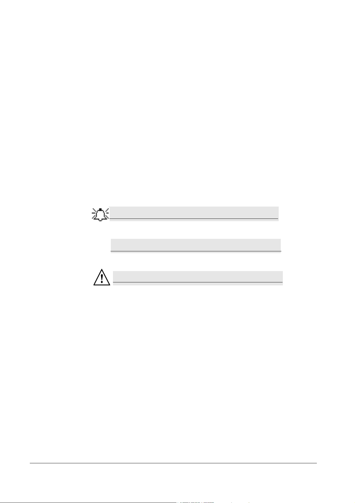
A note is information or remark that receives emphasis and looks as follows:
A caution warns you about possible damage to equipment, and looks as follows:
A warning warns you about possible harm to people and looks as follows:
DataRecorders screen.
Given Imaging Ltd. 1
Page 8
PillCam Platform
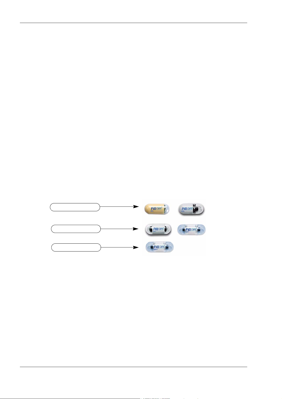
PillCam SB capsules
PillCam ESO capsules
PillCam COLON capsule
Welcome to the PillCam Platform
The PillCam Platform enables minimally invasive visualization of the gastrointestinal tract.
The system consists of:
• PillCam video capsules—PillCam SB, PillCam ESO, and PillCam COLON, that acquire
pictures of the gastrointestinal tract and transmits them to the DataRecorder
• DataRecorder, which stores the images collected during the examination for subsequent video
creation with the full RAPID software
• RAPID software, which processes and transforms the raw image data into a conveniently
viewable RAPID video
PillCam Video Capsule
PillCam video capsules are video cameras for imaging the intestinal tract. The capsules, about the
size of a large vitamin pill, are equipped with tiny battery, transmitters with antenna, and Light
Emitting Diodes (LEDs) for each video camera head, all encapsulated in a biocompatible plastic
casing.
There are three PillCam video capsule types:
• PillCam SB capsules are used for examination of the small bowel.
• PillCam ESO capsules are used for examination of the esophagus.
• PillCam COLON capsules are used for examination of the colon.
PillCam SB capsules contain one video camera while the PillCam ESO and PillCam COLON
capsules each contain two video cameras.
After activation and ingestion, the PillCam video capsule is propelled by peristalsis through the
gastrointestinal tract. The video cameras positioned behind a clear plastic dome acquire images
while the PillCam video capsule travels along the patient's gastrointestinal tract. The transmitter
sends images to the DataRecorder for storage.
For specification and technical parameters of the PillCam video capsules, see System
Specifications on page 32. For Indications and Contraindications, see chapter two of Book 2:
Peforming Capsule Endoscopy.
2 Chapter 1
Page 9

Handling the PillCam Video Capsule
Caution
!
Each PillCam video capsule comes in its own box that enables the handling of the capsule until
ingestion. A magnet close to the capsule in the box keeps it inactive until removal from the box.
The capsule is active immediately after removal from the box.
T o ensure the capsule remains inactive, it must be in the box. PillCam video capsules are packed
at Given Imaging Ltd. in a controlled process, ensuring the capsule is only activated after
removal from its box.
• Removal of a PillCam video capsule from its box activates it.
• Keep in the box until use.
• Store the capsules only in packaging supplied with the product.
• Do not use a PillCam video capsule if packaging is damaged.
DataRecorders
Introduction
The DataRecorder is a compact battery-operated unit worn by the patient during the
examination. It receives and stores the image data transmitted by the PillCam capsule. There are
two models currently available: DataRecorder 2 and DataRecorder 3.
DataRecorder 2
The DataRecorder 2 consists of a receiver, a processor module, and a memory device for storing
the data transmitted by the PillCam video capsule.
The standard DataRecorder 2 Kit includes the following items:
• DataRecorder 2
• Standard RecorderBelt
• Two RecorderBelt extensions
• Pouch + suspenders
• Li-Ion battery pack
• DataRecorder 2 Cradle and adaptor
• 8-lead and 3-lead SensorArray
• DataRecorder 2 Carrying case
Chapter 1 3
Page 10
PillCam Platform
Capsule LED
DataRecorder LED
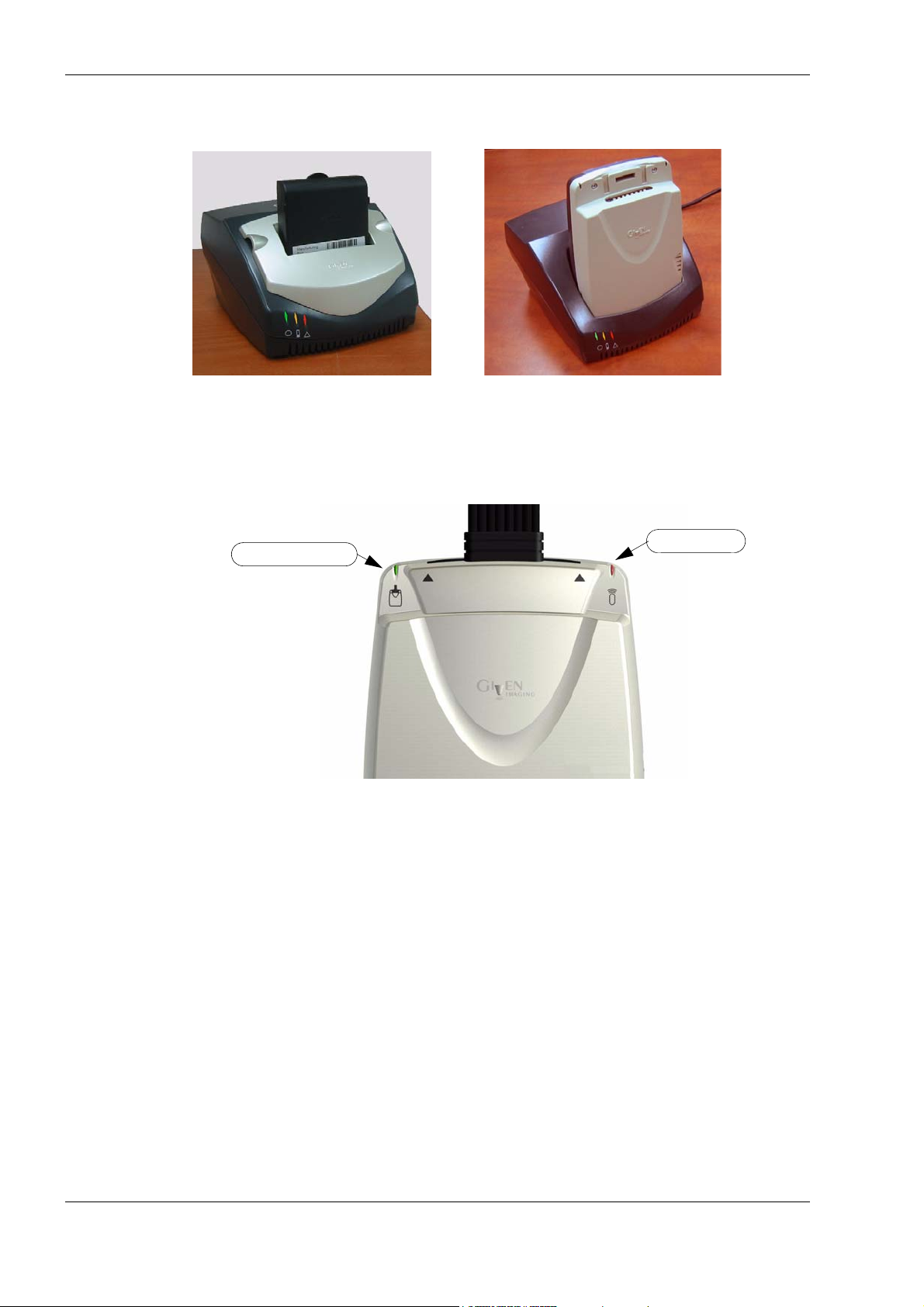
The battery of the DataRecorder 2 is charged in the cradle either with its adaptor or while inside
the DataRecorder 2.
The DataRecorder 2 is ready for operation when its battery is charged and the SensorArray is
connected. When the DataRecorder 2 is on, it starts recording as soon as a signal is received from
any PillCam video capsule. When the capsule LED blinks, the DataRecorder 2 is receiving data.
When the signal from the PillCam video capsule is too weak, the LED does not blink.
DataRecorder 2 Automatic Shutdown
After the DataRecorder 2 has been initialized with patient data, it goes into a standby mode when
removed from its cradle and starts recording as soon as a signal is received from any PillCam
video capsule. If no signal is received, the DataRecorder automatically shuts down after 90
minutes. This feature ensures that the DataRecorder 2 preserves sufficient battery power to record
a complete study.
4 Chapter 1
Page 11
Introduction
Note
DataRecorder 2 LED Indications
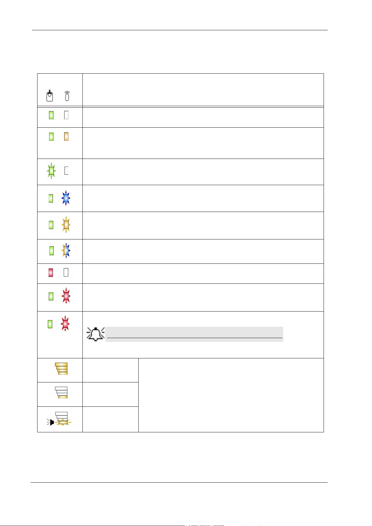
The following table describes the LED indicators and their status/color for each of the most
common DataRecorder 2 events/status.
LEDs
DataRecorder 2 Status
DataRecorder is ON but not initialized. DataRecorder does not capture capsule signals.
DataRecorder is initialized with patient data and ready to capture capsule signals.
DataRecorder shuts down if no capsule signals are received for more than 3 0, 60, or 90
minutes, depending on the DataRecorder software version.
DataRecorder is exchanging status or data with RAPID or RAPID RT.
LED blinking rate varies according to the communication flow.
DataRecorder is capturing capsule signals.
Blinking rate = capsule frame rate.
<20 seconds
>20 seconds
DataRecorder has stopped capturing capsule signals for more than 5 seconds.
DataRecorder is detecting a capsule in sleep mode.
Blinking rate = every five seconds (in any color).
DataRecorder is malfunctioning.
DataRecorder is synchronizing with a capsule. This is normal functioning.
DataRecorder detects capsule signal, but is not recording it. This is a malfunction.
Check the SensorArray connection or have patient move to a different
location.
Maximum Level
Battery Charge level
25%
When charging, the Battery LEDs do not blink.
When DataRecorder is out of the Cradle, the Battery LEDS blink once
every 5 seconds.
Below 10%
Chapter 1 5
Page 12
PillCam Platform
Warning
Note
Auxiliary mains socketD-type connector
USB cable
Power connector
DataRecorder 2 Cradle
The DataRecorder 2 Cradle is used to charge the DataRecorder 2 or to charge a spare battery
externally. It is also used to discharge the battery before starting the recharge, when the Cradle
detects that the battery needs refreshing (i.e., the battery gauge needs calibration). Thus
occasionally, when inserted into the cradle, before charging starts, the Cradle may discharge first
the battery and then start recharging.
The cradle also connects the DataRecorder 2 to the computer for performing patient check-in and
creating a video.The green LED on the cradle indicates that the DataRecorder 2 is charged and
ready for use.
• The red LED, when lit continuously, indicates a defective battery.
• The red LED, when blinking, indicates that there is a problem with the cradle.
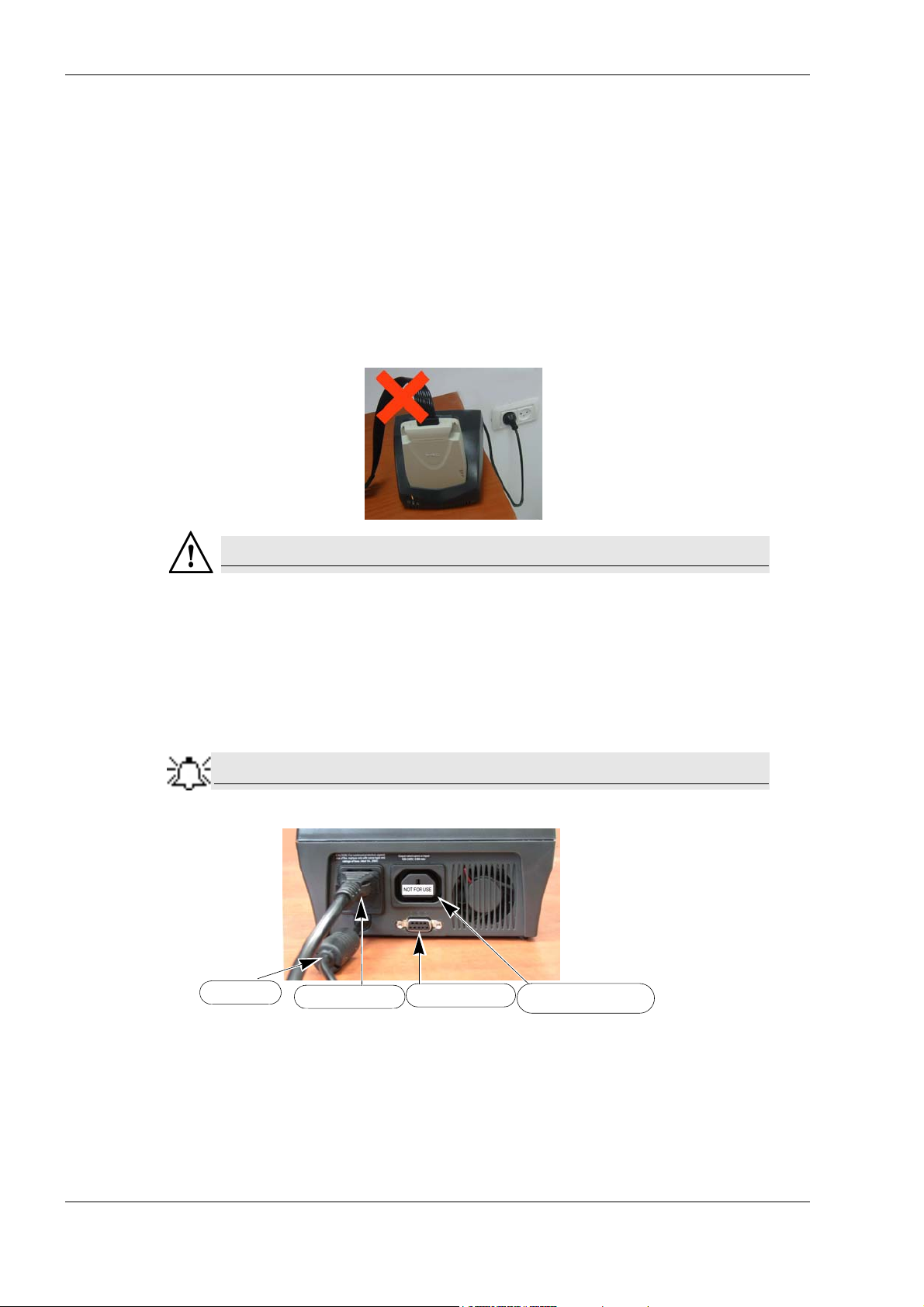
Never connect the DataRecorder 2 to the SensorArr ay while th e Dat aRe corder
2 is in its cradle.
Cradle Connections
There are four connections on the back panel of the cradle. Only two of them are used with
standard operation of the cradle: the power connector and the USB cable connection.
When connecting more than one DataRecorder 2 to the computer, it is
recommended to use a USB-powered hub.
The D-type connector and Auxiliary mains socket-outlet are for service use only.
6 Chapter 1
Page 13
Warning
• The cradle is for indoor use only.
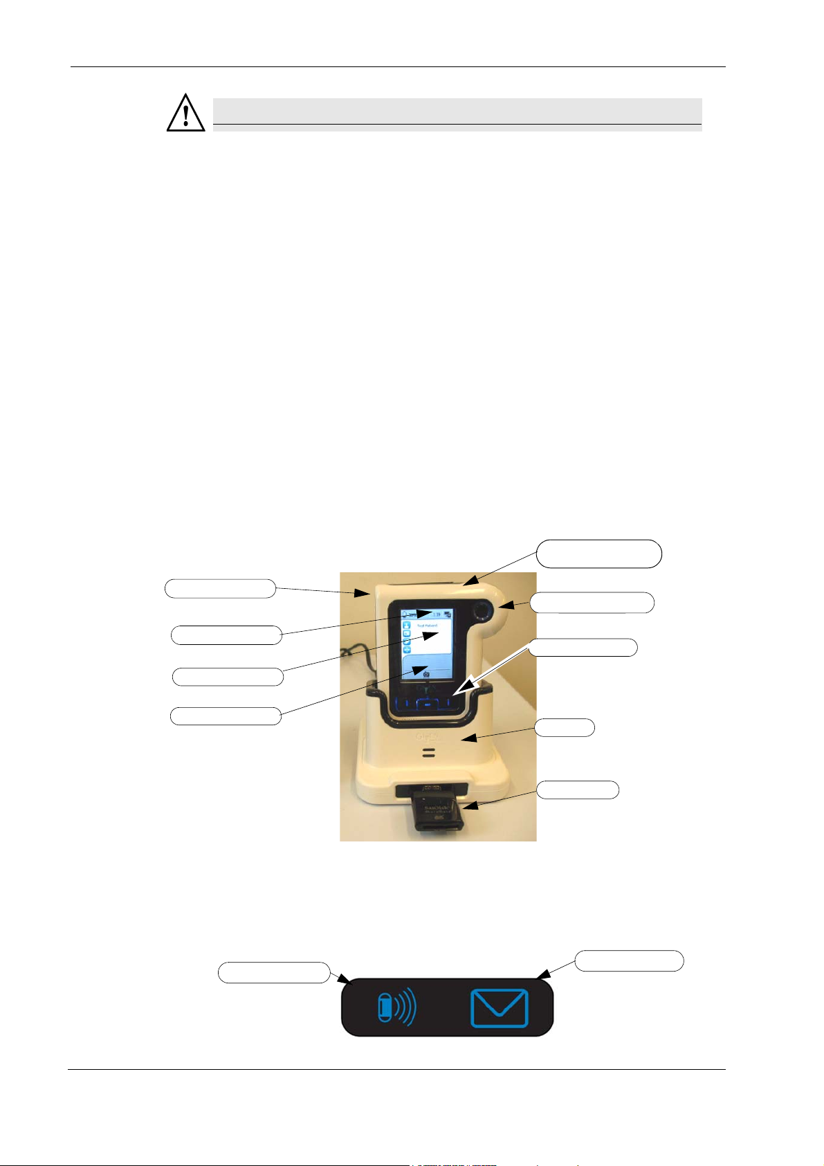
ON/OFF Button
Acknowledge Button
Capsule and Message
LEDs
Line for status icons
Procedure info area
Navigation Buttons
Cradle
Card Reader
Message area
Capsule LED
Message LED
• Never charge non-rechargeable batteries.
• All cells containing mercury , cadmium, or lead as electrochemical substances are
subject to special waste disposal requirements.
• This charger is a class A product. In a domestic environment, this charger may
cause radio interference.
DataRecorder 3
The DataRecorder 3 consists of a receiver, a transmitter, and a memory device for storing the
data transmitted by the PillCam capsule.
The standard DataRecorder 3 Kit includes the following items:
• DataRecorder 3
• Pouch + shoulder strap
• DataRecorder 3 cradle
• External power supply
Introduction
SensorArrays are not part of the standard kit, and are supplied separately.
The battery of the DataRecorder 3 is charged while the DataRecorder is in its cradle.
The DataRecorder is ready for operation when its battery is charged, removed from the cradle,
and the SensorArray is connected. When ON, the DataRecorder initiates pairing procedure (see
DataRecorder-Capsule Pairing in chapter 4 of the Procedure Manual) as soon as a signal is
received from a capsule. When the capsule LED on the DataRecorder blinks in blue, the
DataRecorder is receiving data from a paired capsule.
Chapter 1 7
Page 14

PillCam Platform
Acknowledge Button
The Acknowledge button is used by the patient in response to DataRecorder messages, including
regimen instruction messages during post ingestion regimen (see Post Capsule Ingestion
Instructions in Book 2: Performing Capsule Endoscopy) to acknowledge receiving the message.
Navigation Buttons
The Navigation buttons are used:
• For manual capsule paring process (see DataRecorder-Capsule Pairing in Book 2: Performing
Capsule Endoscopy, Chapter 4)
• To interact with the DataRecorder (see Navigation Buttons Legends on page 12)
Battery Status
The battery icon on the screen indicates the status of the battery in 10% increments.
When the battery charge is below 10% the battery icon turns red. When the battery charge is
below 5% the DataRecorder shuts down.
When the DataRecorder 3 is charging in its cradle, the bottom LED in the cradle is orange. When
the DataRecorder is ready for use, the bottom LED in the cradle is green.
DataRecorder Automatic Shutdown
After the DataRecorder has been initialized with patient data, it goes into a standby mode when
removed from its cradle and starts recording as soon as a signal is received from a paired capsule.
If after 90 minutes no paired signal is received, the DataRecorder automatically shuts down.
The DataRecorder 3 also turns off five minutes after End of Procedure .
8 Chapter 1
Page 15

DataRecorder 3 LED Indications
The following table describes the LED indicators and their status/color for each of the most
common DataRecorder 3 events/status.
LEDs DataRecorder 3 Status
DataRecorder is initialized with patient data and ready to capture capsule signals.
DataRecorder shuts down if no capsule signals are received for more than 90 minutes.
DataRecorder is receiving capsule signals before capsule pairing is achieved.
Blinking
Blinking
Blink every 5 seconds
Blinking rate = capsule frame rate
DataRecorder is receiving paired capsule signals.
Blinking rate = capsule frame rate.
DataRecorder has stopped receiving capsule signals for more than 5 seconds.
Introduction
Blinking
Blinking
DataRecorder has started downloading.
DataRecorder has stopped recording because the memory card is full.
There is an instruction on the DataRecorder screen.
DataRecorder is malfunctioning.
DataRecorder detects capsule signal, but is not recording it.
This is a malfunction. Check the SensorArray connection or have patient move to a
different location.
The LEDS on the navigation buttons blink in blue once every 5 seconds when the
DataRecorder is on, out of the cradle and the LCD screen is off.
Pressing any of the navigation buttons when the LCD screen is OFF will turn the LC D
screen ON.
Chapter 1 9
Page 16
PillCam Platform
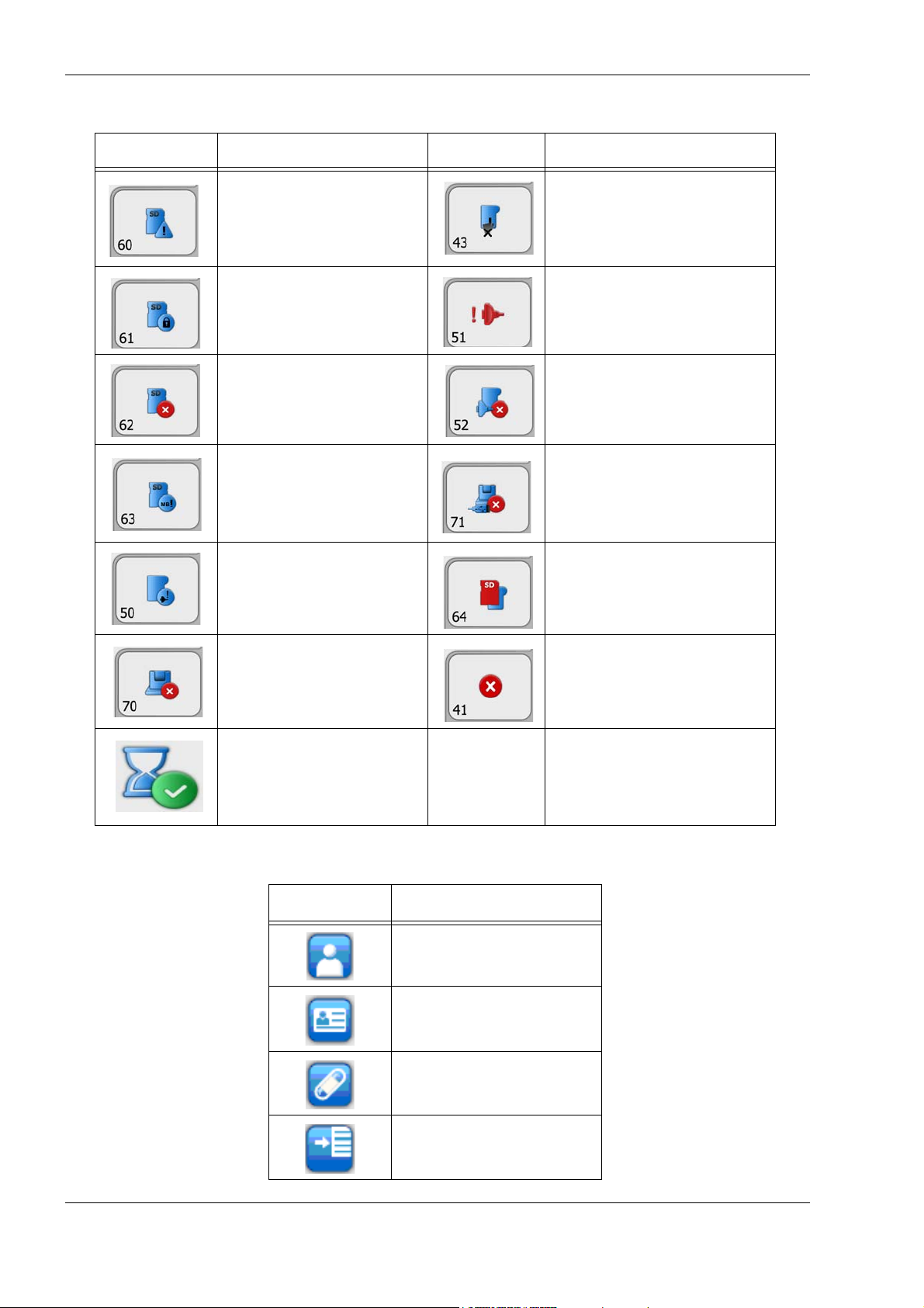
DataRecorder 3 Error Message Guide
Popup Message Popup Message
No valid approved memory
card is detected.
Verify approved card is in the
DataRecorder.
Do not move DataRecorder from
cradle
Memory card is write-protected
Memory card error.
Remove + reinsert card.
Insufficient memory on card
SensorArray not connected.
Connect the SensorArray
Cradle error
SensorArray hardware failure.
Consult a technician.
Wrong SensorArray type
No USB connection to cradle.
Check connection. If connection is
OK and error persists, consult a
technician
Wrong software on memory card
Fatal error.
Consult a technician.
End of procedure
DataRecorder 3 Check-in Screen Icons
Icon Name
Patient Name
Patient ID
Procedure
Regimen
10 Chapter 1
Page 17
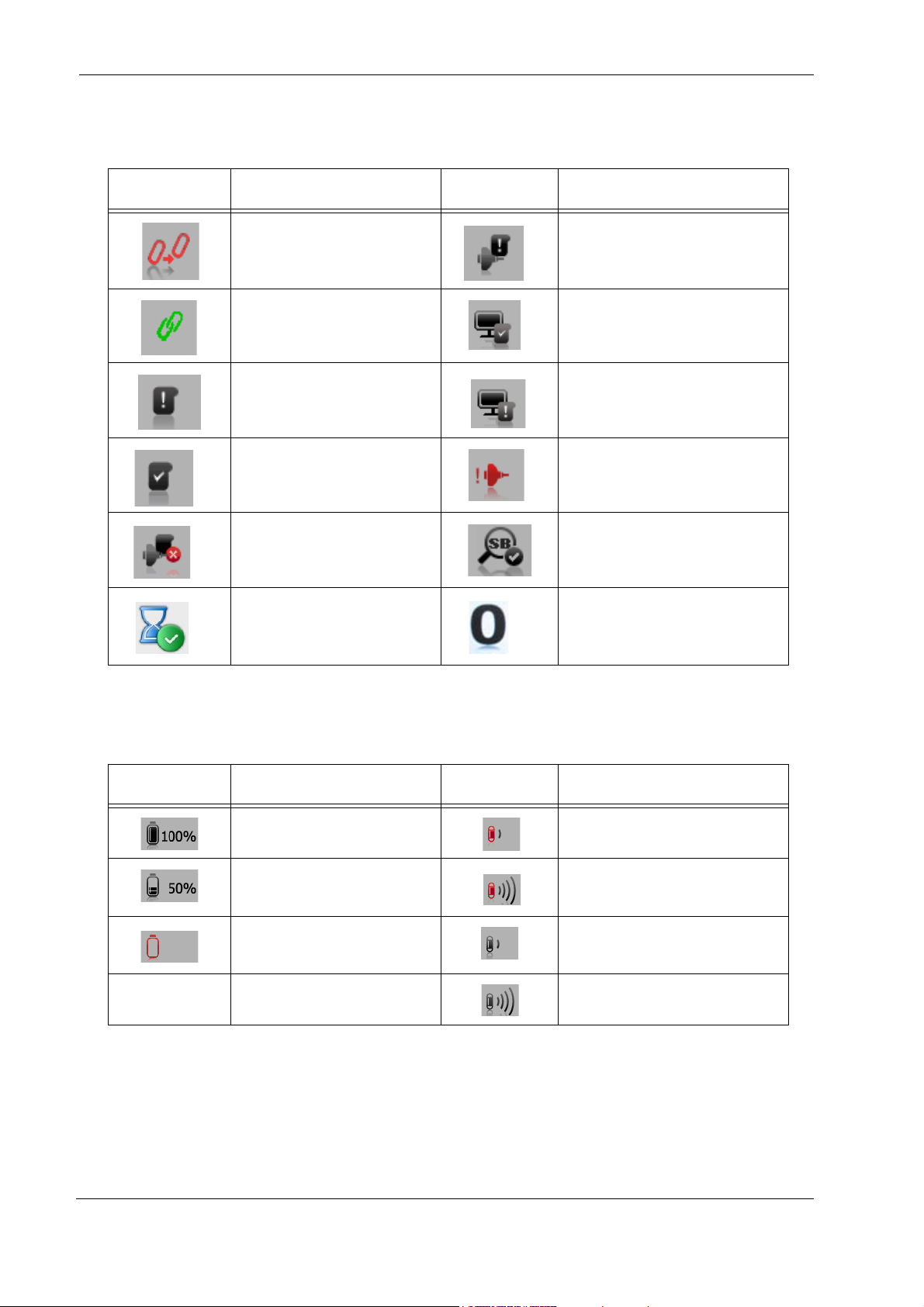
DataRecorder 3 Screen Icons
The following icons appear in the top status line of the DataRecorder screen.
Icon Explanation Icon Explanation
Start pairing procedure SensorArray not connected
Pairing succeeded DataRecorder is initialized
Introduction
Data not downloaded
Data downloaded SensorArray failure
Wrong SensorArray type Small bowel detection
End procedure, Memory full
DataRecorder is waiting for
initialization
Regimen Reminder numbers
appear in status line when in Real
Time Viewing mode
Battery and Capsule Icons
The following icons appear in the top status line of the DataRecorder screen.
Icon Battery Status Icon Capsule Reception Status
Battery fully charged Signal weak, recording with noise
Battery charge level at 10%
intervals
Battery empty, DataRecorder
shuts down
Chapter 1 11
Signal strong, recording with
noise
Signal weak, but recording OK
Signal strong, and recording OK
Page 18
PillCam Platform
Warning
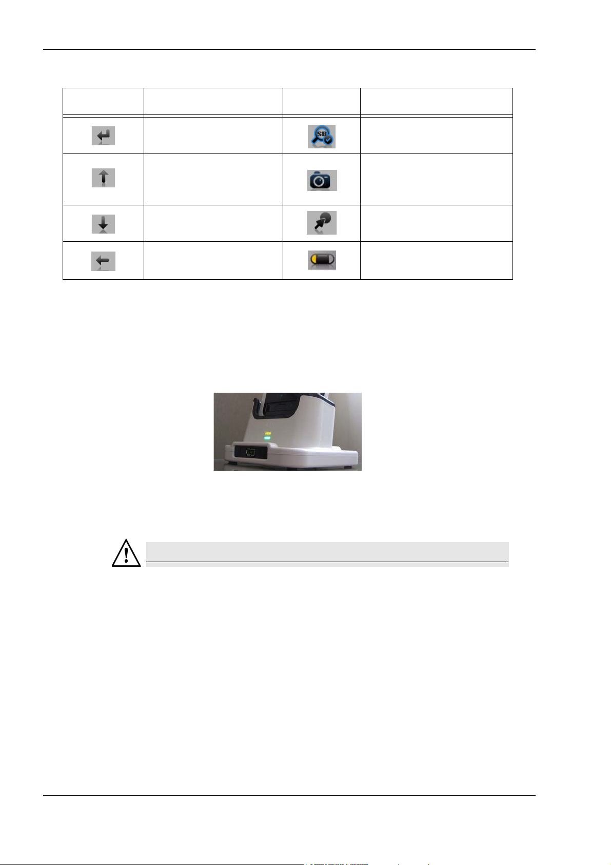
Navigation Buttons Legends
Icon Action when pressed Icon Action when pressed
Confirm
Confirm SB detection and activate
instruction #1
Activate Real-Time viewing
Scroll up
(followed by pressing the left and
right buttons)
Scroll down Mark frame
Exit Real-Time viewing
Switch video head (in Real-Time
viewing mode)
DataRecorder Cradle
The DataRecorder Cradle is used to charge the DataRecorder.
The cradle also connects the DataRecorder to the computer for performing patient check-in and
creating a video.
• The top LED is orange when the DataRecorder is in the cradle.
• The bottom LED is orange when charging the battery.
• The bottom LED is green when the DataRecorder is fully charged.
Never connect the DataRecorder to the SensorArray while the DataRecorder is
in its cradle.
12 Chapter 1
Page 19
Introduction
Note
Warning
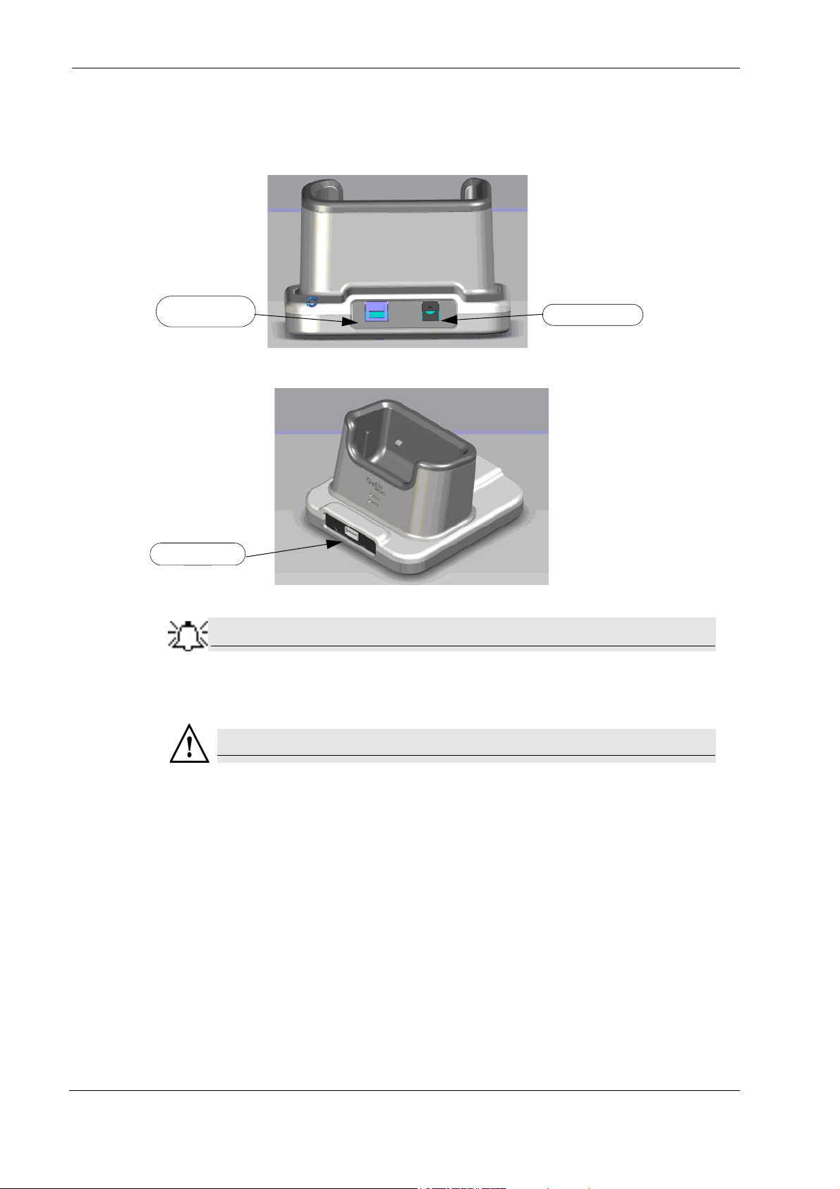
USB Connection
to computer
Power connector
USB connector
Cradle Connections
There are two connections on the back panel of the cradle: the power connector and the USB
connection to computer.
At the front of the cradle is a USB socket for connecting a card reader or USB storage device.
Connect only USB storage devices, DataRecorder 3 memory cards (in its
reader), or self-powered external hard drives to the DataRecorder 3 cradle.
Other USB devices may not function as indicated.
• The cradle is for indoor use only.
• Never charge non-rechargeable batteries.
• All cells containing mercury , cadmium, or lead as electrochemical substances are
subject to special waste disposal requirements.
• This charger is a class A product. In a domestic environment, this charger may
cause radio interference.
Chapter 1 13
Page 20

PillCam Platform
Caution
!
External Power Supply
The Cradle is connected to the mains power through an external power supply.
Use only this power supply.
RecorderPouch
The DataRecorder 3 RecorderPouch is a pouch with an adjustable strap to hold the DataRecorder .
The patient must wear the DataRecorder at all times while the PillCam video capsule is active
inside the patient. Use the waist strap to anchor the DataRecorder and the SensorArray connector
to the patient’s body.
SB SensorBelt
The SB SensorBelt receives data from the PillCam video capsule and transfers it to the
DataRecorder. The sensor is connected to the DataRecorder module by a flexible cable and is
worn at the waist of the patient over a thin shirt. The SB SensorBelt is used for PillCam capsule
endoscopy of the small bowel.
SensorArray
The SensorArray receives data from the PillCam capsule through the sensors and transfers it to
the DataRecorder. Each sensor is connected to the DataRecorder module by a flexible cable. The
sensor is built of a flexible printed circuit board (PCB) and is attached to the skin by means of a
disposable, medical adhesive sleeve.
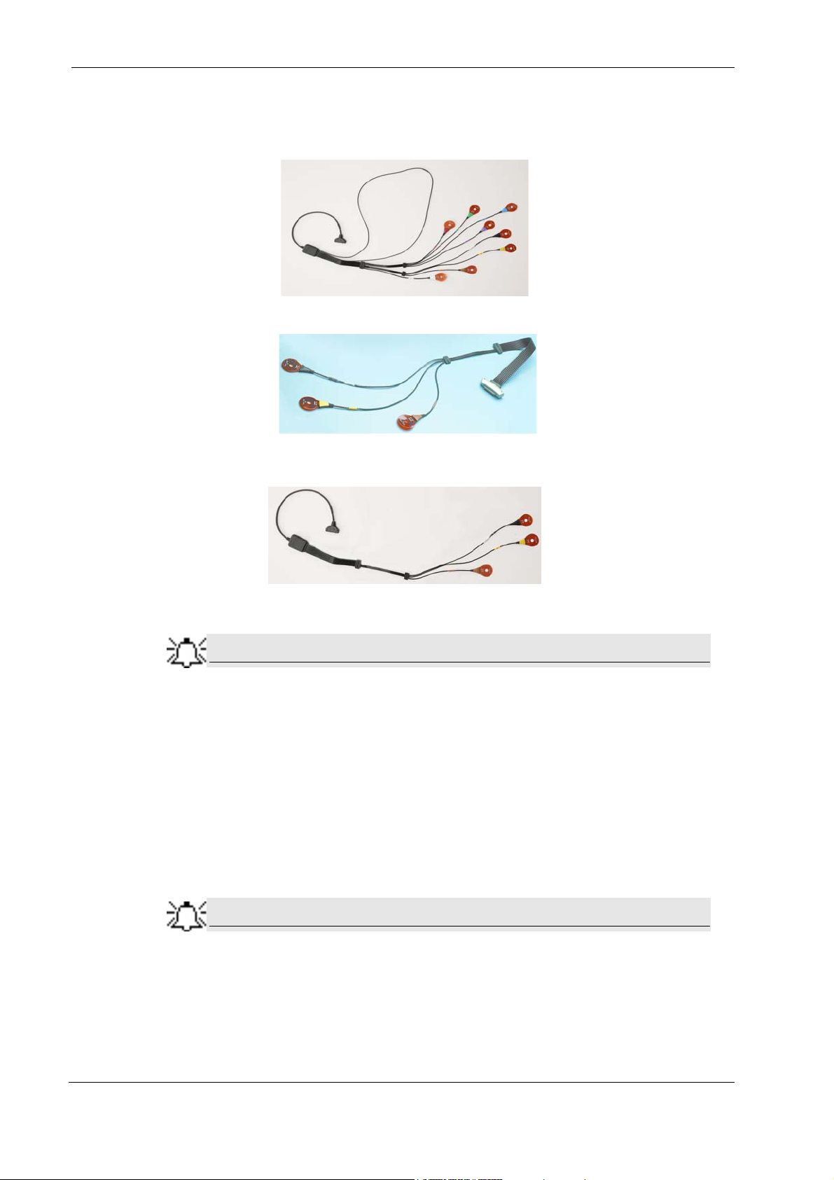
The SensorArray used in a capsule endoscopy depends on the caspule type and the DataRecorder
type:
• 8-lead SensorArray: used with DataRecorder 2 and PillCam SB and PillCam COLON
capsules
14 Chapter 1
Page 21
Introduction
Note
Note
• 8-lead SensorArray DR3: used with DataRecorder 3 and PillCam SB 2 and PillCam COLON
2 capsules. This SensorArray also transmits control signals to the COLON 2 capsule through
the transmitter loop antenna.
• 3-lead SensorArray: used with DataRecorder 2 and PillCam ESO 2 capsules
• 3-lead SensorArray DR3: used with DataRecorder 3 and PillCam ESO 3 capsules
All components of the PillCam Platform are Latex free.
Given Workstation
The Given Workstation is a dedicated computer designed for processing, displaying, storing the
acquired images, and generating the RAPID videos.
T o control access to the Given Workstation and to make sure that only authorized personnel may
use the relevant files on the Given Workstation, a multi-user configuration is provided, see
Multi-User Setup on page 27.
When RAPID is installed on a persona l computer , it functions nearly identically
to the Given Workstation. Throughout this manual, references to the
workstation apply also to the RAPID compu ter except whe re oth erwise note d.
Chapter 1 15
Page 22

PillCam Platform
RAPID 7 Software
RAPID 7 supports PillCam capsule endoscopy of the GI tract with all PillCam video capsules.
RAPID 7 supports patient check-in/DataRecorder initialization, video creation, viewing of the
RAPID video, and generation of a Capsule Endoscopy Report.
16 Chapter 1
Page 23

Setup Requirements
Note
Caution
!
Note
Set up your office to accomodate the new PillCam Platform. Review the following Workstation
specifications:
Four electrical outlets are required to connect the following components: Workstation computer ,
monitor, printer, and one cradle. Each additional cradle requires an additional outlet.
Chapter 2
Setting Up the System
You may use a Given approved power strip.
Do not connect any component of the PillCam Platform to the same outlet as
any appliance or device that has a high power requirement (refrigerators,
generators, devices with motors, etc.). When setting up the system, make sure
that the total power requirements for all of the devices connecte d to a single
outlet or circuit do not exceed the rated limit for that circuit. If you are n ot sure of
the rated limit, please consult your maintenance department or an electrician.
Do not use a KVM Switch with the PillCam Platform.
The dimensions of the Workstation components are listed below:
Extra space is needed for air circulation and cable connectors behind the
Workstation.
Given Imaging Ltd. 17
Page 24

PillCam Platform
Warning
Caution
!
Given Workstation
The footprint of the Given Workstation is about 18 cm (W) x 47 cm (D) x 45 cm (H).
DataRecorder and Cradle
The cradle of any DataRecorder with its cable connections have a footprint of about 8-12
inches (20-30 cm).
The DataRecorder is kept in its cradle when not in use.
Storage Space for the PillCam Capsule Box
Provide a storage space that is protected from any powerful electromagnetic source, for storing the PillCam video capsule 1box.
Main Platform Components
Following is a list of items which you need to connect in order to set up the PillCam Platform:
• Given Workstation
• Monitor
• Keyboard
• Mouse
• Printer
• DataRecorder with Cradle
Connecting the Components
The Given Workstation has either an automatic or a manual Voltage Select
Switch. In case the workstation has a manual switch:
• verify that the workstation’s voltage is set according to the local voltage prior to
connecting the Given Workstation to the wall outlet.
• If the voltage is not set according to the local volt age, do no t connect the system .
Call the Given
Voltage mismatch will damage the Given Workstation.
Customer Support.
18 Chapter 2
Page 25
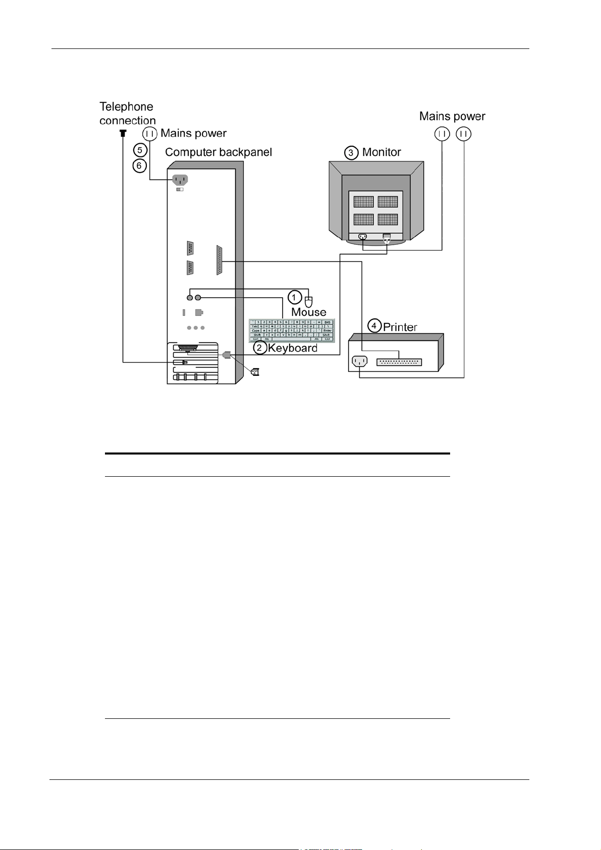
Use the following sketch as an aid in setting up the PillCam Platform:
Chapter 2
Dell Given Workstation
The following table lists the items that connect to the Given Workstation back panel:
Connection Explanation
Power cord Connects the Given Workstation to the electric socket.
Keyboard Connects the Given Workstation to the keyboard.
Mouse Connects the Given Workstation to the Mouse
Monitor Connects the Given Workstation to the monitor.
Parallel Port Connects to the parallel printer cable that connects the
Given Workstation to the printer.
USB Port Connects to the USB cable that connects the Given
Workstation to the printer, as an alternative to using
Parallel Port.
USB 2 Port The USB 2.0 ports connect to the USB cables that connect
the Given Workstation to the DataRecorder Cradle and to
the Card reader.
Modem Connects to the telephone cable that connects the Given
Workstation to a phone line. Don't connect at setup.
Connect the modem only if instructed to do so by Given
Customer Support.
Chapter 2
19
Page 26

PillCam Platform
Note
Warning
You will need the telephone connection only for some maintenance operation
on your WorkStation. Connect the modem of the Given Workstation only when
instructed to do so by Given Customer Support. To connect, insert the Modem
cable into the Modem connector and the other jack phone connector of the
Modem cable into the phone outlet.
Connecting the Given Workstation
1. Connect the Mouse cable to the Mouse connector.
2. Connect the Keyboard cable to the Keyboard connector.
3. Connect the monitor to the Workstation. a. Unpack the monitor.
b. Using the provided stencil, apply to the front of the monitor the adhesive black label
of the Given logo included in the System Accessory box.
c. Connect the DVI-VGA adaptor to the monitor connector at the Workstation’s back
panel.
d. Connect the monitor cable to the DVI-VGA adaptor at the Workstation’s back panel.
4. Connect the printer to the LPT connector or to the USB connector, depending on the printer’ s
connection cable.
5. If the Workstation’s voltage setting is manual, verify that the Workstation’s voltage matches
the local voltage. If it does not, call Given Customer Support.
Do not connect the components to the wall electric outlet until you verify the
Workstation voltage matches the local voltage.
After voltage verification, connect the power cable of the Given Workstation to the electric
6.
outlet.
7. Connect the power cable of the monitor to the wall electric outlet.
20 Chapter 2
Page 27
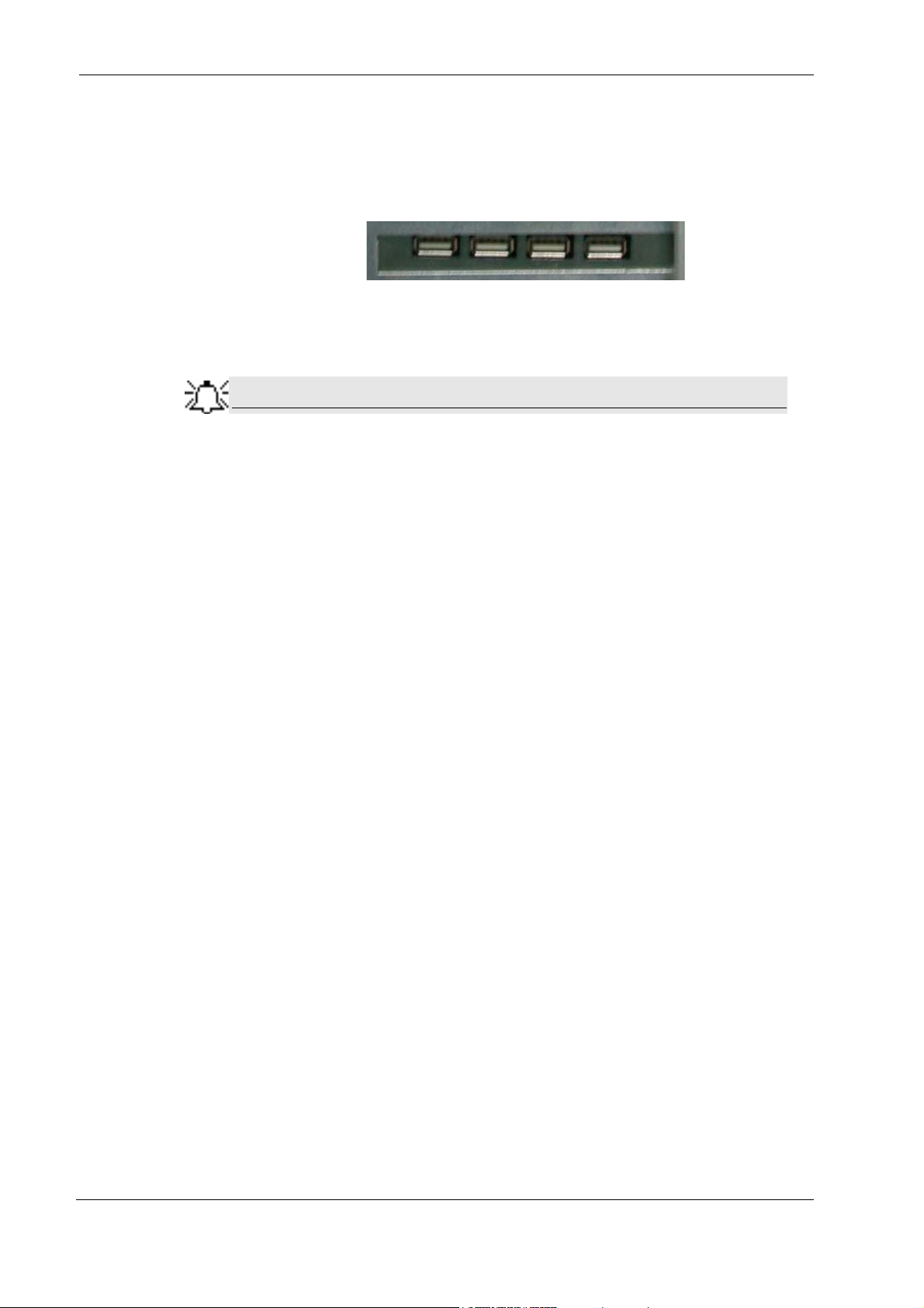
Connecting the DataRecorder Cradle
Note
You can connect the cradle only to the USB2 ports that are side by side in a separate slot on the
back panel of the Workstation.
If you are not using a Given Workstation, use a USB hub for connecting more than one cradle to
your computer.
If you use more than one cradle, make sure each one is connected to a
different power outlet.
Chapter 2
Chapter 2
21
Page 28

PillCam Platform
22 Chapter 2
Page 29

Before installing any new application, close all other applications currently running on the
computer.
RAPID Installation
1. Insert the RAPID 7 Installation disc into the DVD drive. The RAPID 7 installation menu
screen appears.
Chapter 3
Software Installation
2. Click Install RAPID Access v. 7. The following screens appear.
Given Imaging Ltd. 23
Page 30
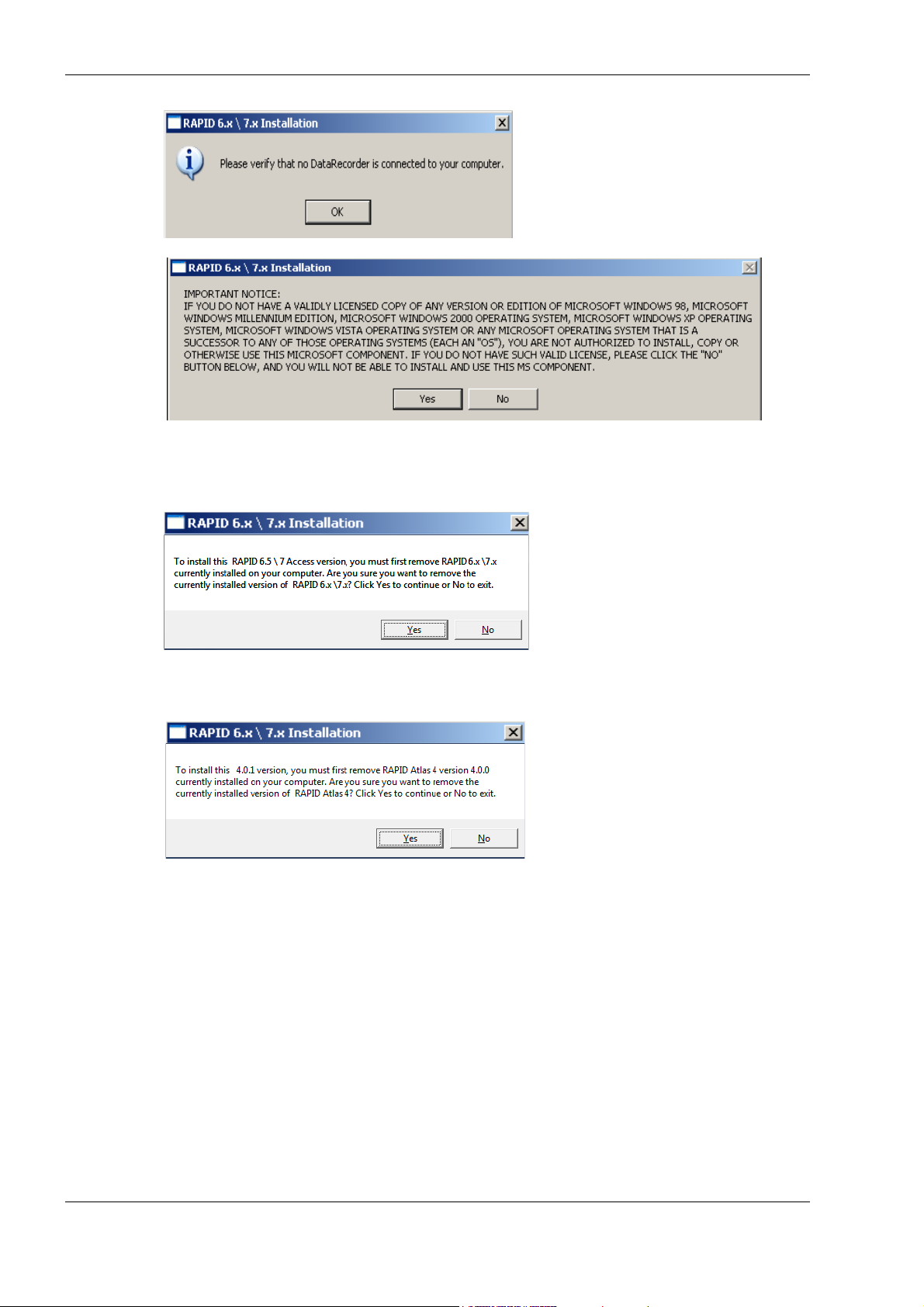
PillCam Platform
3. If you have a valid licensed copy of the Operating System, click Yes.
The following screen appears.
4. Click Yes. The following screen appears.
24 Chapter 3
Page 31
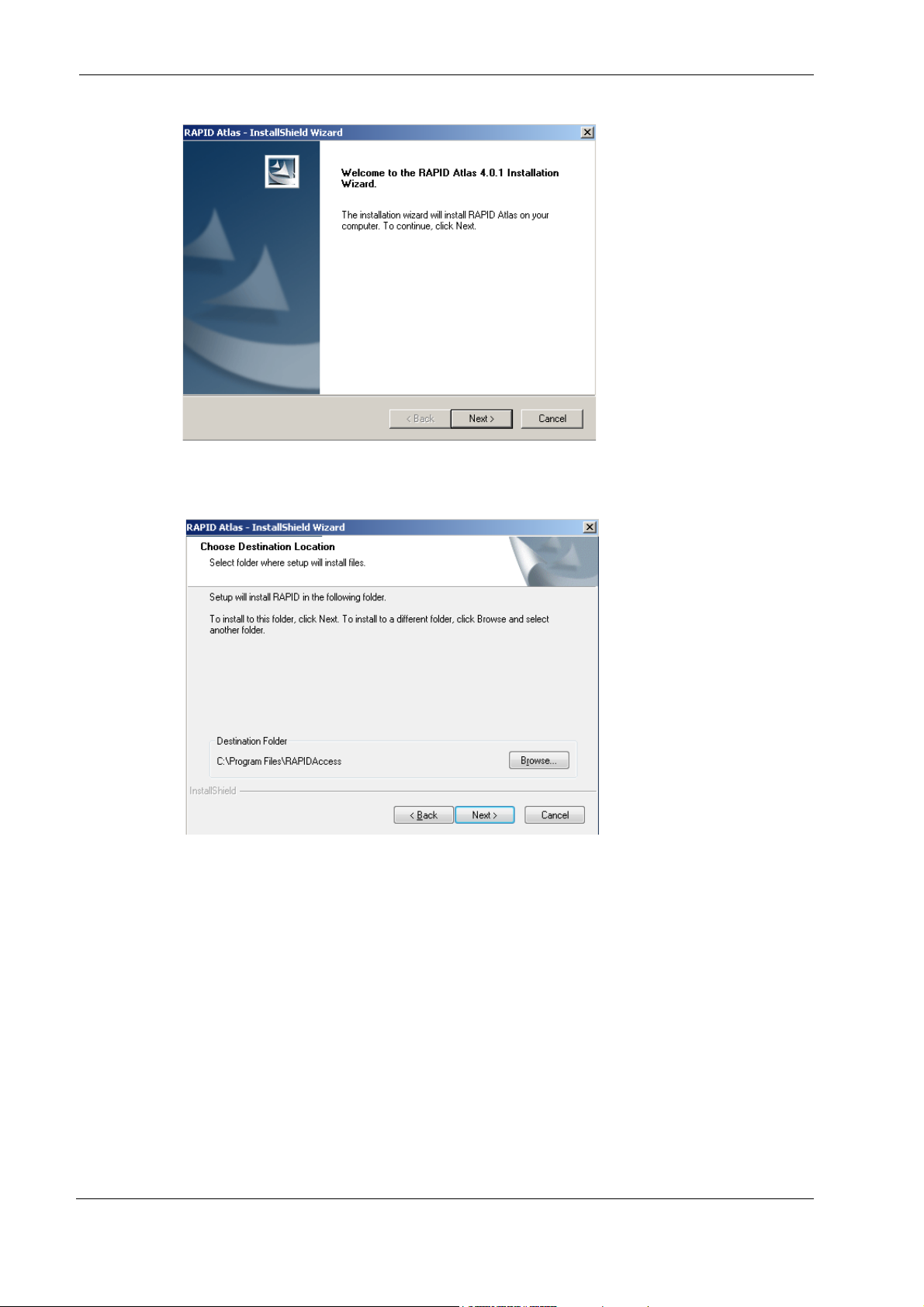
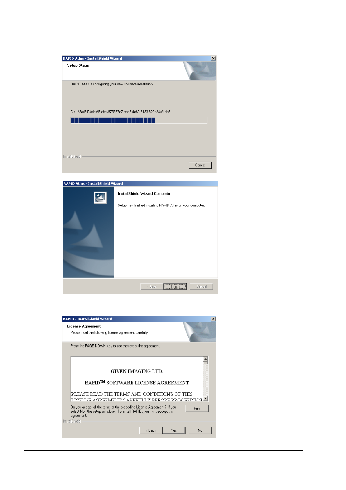
5. Click Yes. The InstallShield Wizard for the RAPID Atlas appears.
6. Click Next. The following screen appears.
RAPID Installation
Chapter 3 25
Page 32
PillCam Platform
7. Click Browse if you wish to install in a dif ferent location. To continue with the installation,
click
Next. The following screen appears.
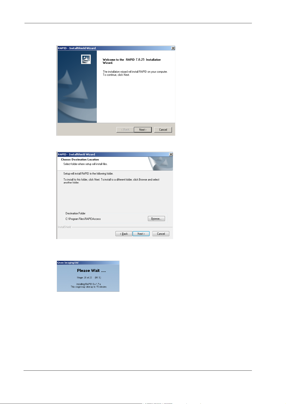
8. Click Finish. As soon as the progress bar is full, the License Agreement screen appears.
26 Chapter 3
Page 33
RAPID Installation
9. To continue the installation and accept the license agreement, click Yes. If you wish to
print the license agreement before reading it, click
10. Click Next. The following screen appears.
Print. The following screen appears.
11. Click Browse if you wish to install in a different location. T o continue with the installation,
Next. The Please Wait screen appears and the installation starts.
click
Depending on the computer configuration, this stage takes at least several minutes.
If the installation fails, the following message appears:
failed.
In that case, restore the previous version of the RAPID Software.
RAPID installation has
To restore:
a. Insert RAPID 7 Installation CD.
b. Click Install RAPID and follow the instructions on the screen.
Chapter 3 27
Page 34
PillCam Platform
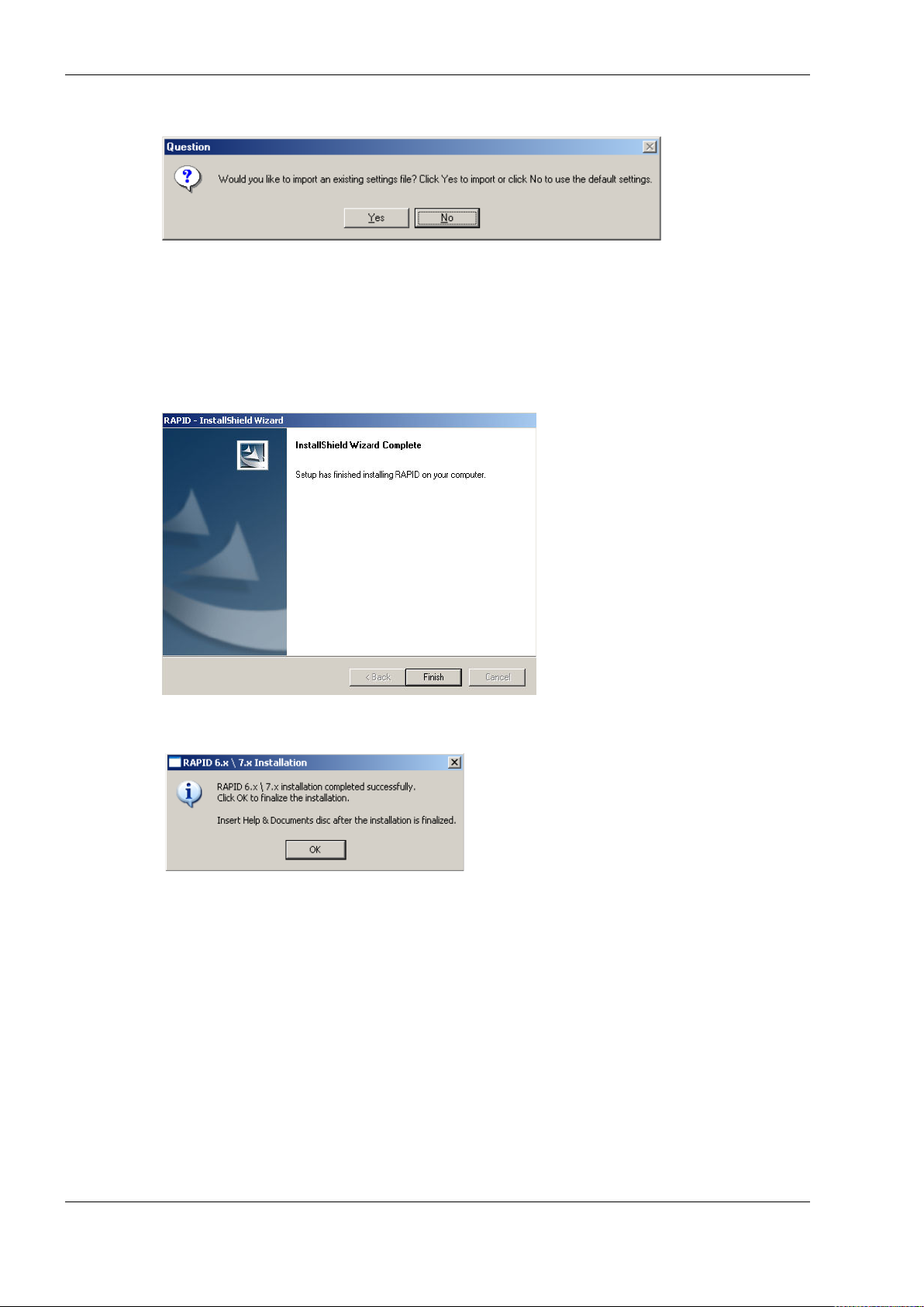
12. Just before the end of the installation, the following screen appears.
This refers to an exported System Wide Settings xml file.
If you wish to import such a file, click Yes and browse for the file location. A message warns
you that the imported file will overwrite an existing settings file and asks whether you wish
to continue.
13. Click Yes. If RAPID installation continues uninterrupted, the following screen appears as
s
oon as all the stages are completed.
14. To complete the installation, click Finish. The following screen appears.
egistration
R
Unrestricted use of RAPID requires registration via the Given registration center. You must
supply requested information to obtain the Registration Key.
28 Ch
apter 3
Page 35
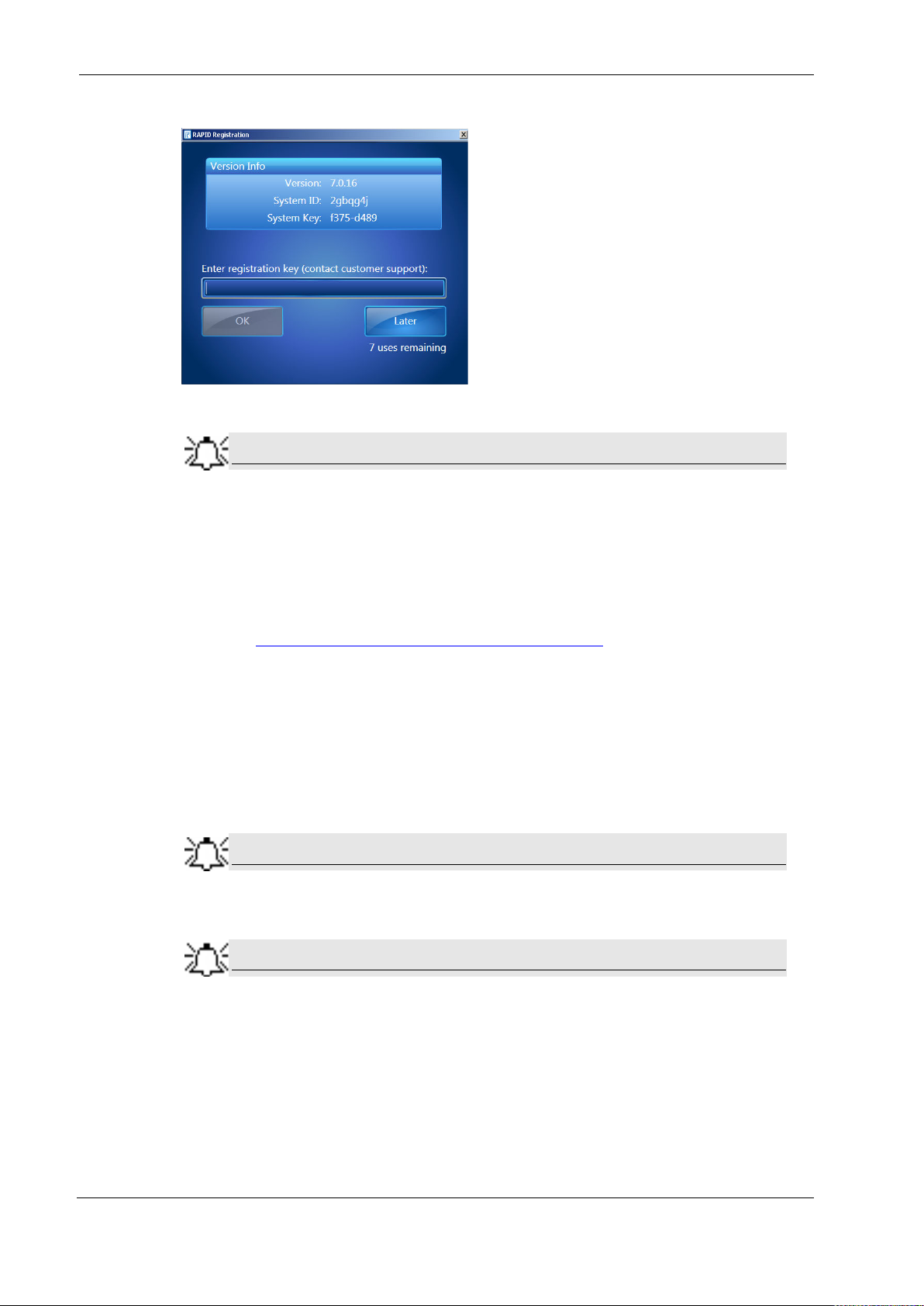
The registration screen appears at the end of the installation process:
Note
Note
Note
Keep the registration window open until you finish the registration. Each time
you open the registration window, a new System Key appears and any
Registration Key based on a previous System Key will not be accepted.
RAPID Installation
If you click Exit, you can open and use the RAPID software, but after seven
uses without registering, you must first perform registration in order to use
RAPID.
15. Obtain a Registration Key via the Given registration center online or by phone:
• online: https://portal.givenimaging.com/RapidRegistration
• by phone: call your local Given customer support center
16. Be ready to provide the Given registration center with the following information:
• System ID (from the registration screen)
• System Key (from the registration screen)
• RAPID DVD serial number (supplied with the DVD)
• Your customer ID
17. Enter the Registration Key received from the Given registration center.
The registration process uses ONLY lower case letters and numbers.
18. Click OK.
If you do not register during installation, the next six times you open RAPID, it
will ask you to register. After seven uses without registering, you cannot use
RAPID without first performing registration.
Chapter 3 29
Page 36

PillCam Platform
Wide Screen Compatibility
In order to get optimal image and reduce risk of getting blurred or distorted images and fonts, the
user should set his display resolution according to his screen manufactures' recommendations
with these restriction in mind:
• RAPID's minimal supported horizontal resolution is 1024.
• RAPID's minimal supported vertical resolution is 768.
For example here some recommended resolutions for different screens:
Aspect Ratio
4:3 1024 x 768
16:9 1360 x 768
16:10 1280 x 800
Minimum
Resolution
30 Chapter 3
Page 37

System Administration
Different users in the RAPID may be defined. The settings values set by each user are saved so
that each time that user logs in to the system, the relevant settings are in effect. Thus, different
users may set different use profiles for themselves. Each user needs to log in with his or her
username and password.
The default password of the user rapid is blank (no need for password), the default password of
the user rapidadmin is rapidadmin (case sensitive). The password for rapidadmin can be
changed by the rapidadmin user.
Chapter 4
Multi-User Setup
The user rapidadmin is meant to be used by a site-assigned system administrator to define
additional users as required.
To Define a User
1. When Windows (re)starts (on a computer installed with RAPID) after completing RAPID
installation, the Windows
2. In the User field type rapidadmin (not case sensitive). In the password field type in your
password (if you haven't changed it since installation, it is still rapidadmin). Click
Log On to Windows screen appears.
OK.
Given Imaging Ltd. 31
Page 38
PillCam Platform
Note
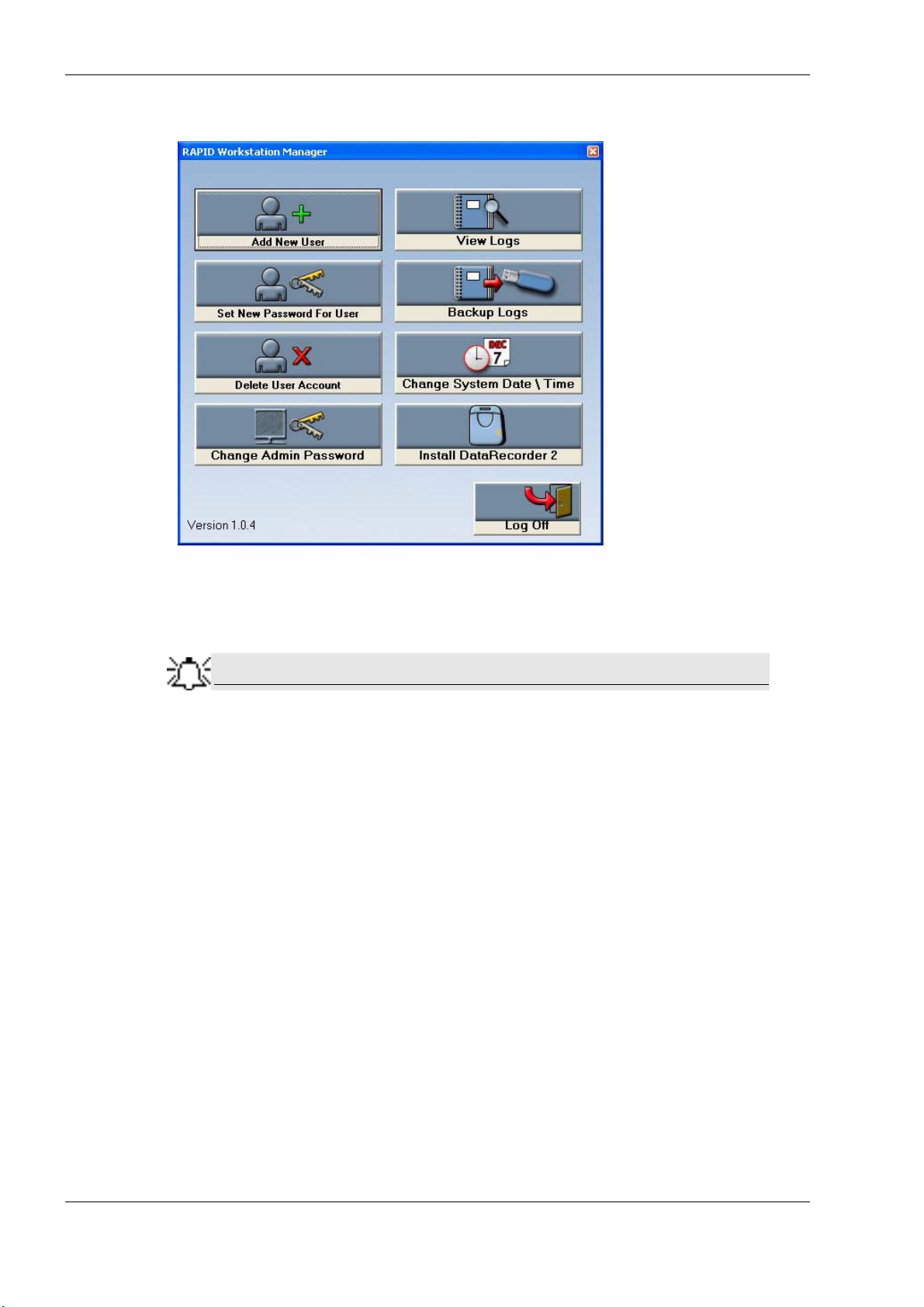
3. Wait for the Given Workstation Manager screen to appear.
4. Click Add New User. The Add New User screen appears.
5. Type in a new User name and Password for the new user.
The password you type in at this stage is a temporary password. The user is
requested to change it when he logs on for the first time.
Click Add User. The message User xxx was added successfully appears.
6.
7. Repeat steps 4–6 for each new user.
To Delete User Account
1. Click Delete User Account. The Delete User Account screen appears.
2. From the list, select which user you want to delete and click Delete User.
The message
3. Click Yes. The message xxx Account was deleted successfully appears.
You chose to delete xxx User. Are you sure? appears.
To Set a New Password for a User
If a user has forgotten his password, you can create a new one.
1. Click Set New Password For User.
2. From the list, select the relevant user.
3. Type the new password in the New Password field, and in the Confirm New Password
field.
32 Chapter 4
Page 39

Multi-User Setup
Note
Note
This new password will again be a temporary one, to be changed when the
user logs on for the first time with this password.
Click Set Password.
4.
The message
xxx’s Password was changed successfully appears.
To Change the Password of the Administrator
1. Click Change Admin Password.
Change Rapidadmin Password screen appears.
The
2. Type in your current password in the Old (Current) Password field.
3. Type in your new password in the fields New Password and Confirm new Password.
4. Click Change my Password.
The message
RAPID Administrator Password was changed successfully appears.
For security reasons, all users should change their default passwords to a
chosen password.
Change the Given Workstation’s Time and Date
Access to the standard Date/Time properties screen of Windows is disabled on a Worksta tion
with RAPID 7 installed. Only the administrator can change the time and date of the system.
1. Click Change System Date/Time. The Date/Time properties screen appears.
2. Make the desired changes and click OK.
3. Log off as Rapidadmin user.
System Logs
System Logs are all the actions performed on the W orkstation.The following items are reco rded
into the system log files:
• the physician (username) who performed the action
• the time and date of the action
• what action was performed (log on, log off, all actions such as adding, deleting and
printing data)
The
Given Workstation Manager screen allows you to view the logs and to create a backup of
the logs.
Chapter 4 33
Page 40
PillCam Platform
To View the Logs
To view the logs, click View Logs. The Log Viewer screen appears.
To view more details about one of the events, select and double click the relevant line and the
Event Properties screen of that specific action appears.
To Create a Backup of the Logs
Creating a backup of the logs involves saving the data to a removable storage device (such as CD,
Disk-On-Key, or USB Mass Storage Device) and deleting this data from the Workstation.
1. Connect your storage device or media to the Workstation.
2. Click Backup Logs. The Logs Backup screen appears.
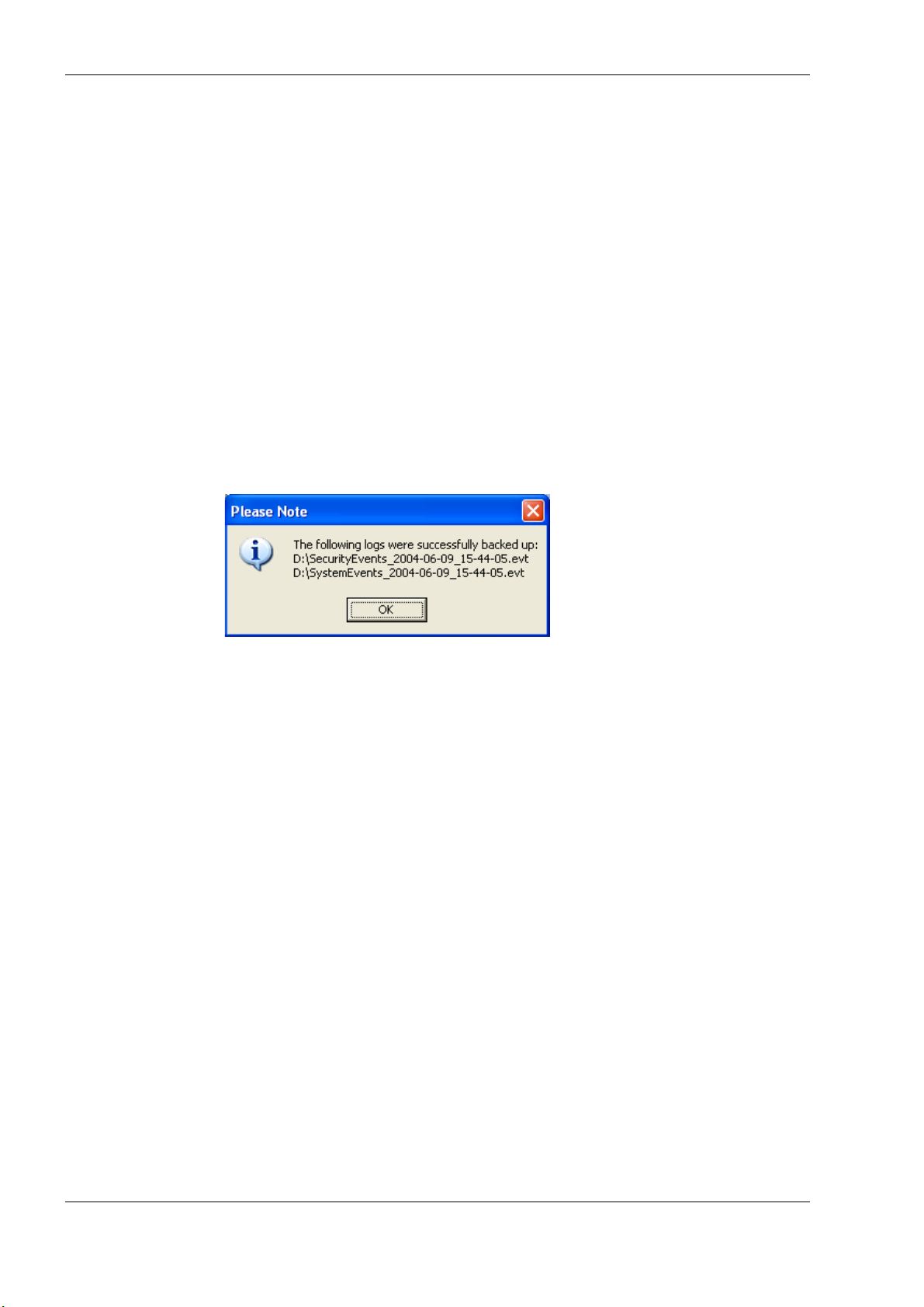
3. Select the relevant removable disk from the list and click Backup. Both the Security Events
and the System Events are backed up through this command. The following message
appears:
4. Click OK.
The system will delete these files once they are backed up successfully onto a removable
device. To check this, click
View Logs again on the Given Workstation Manager screen. The
system log will be empty and the security log shows that the logs were backed up.
5. Click Log Off in the Given Workstation Manager window.
6. Click Yes to confirm exit.
34 Chapter 4
Page 41
System Labeling
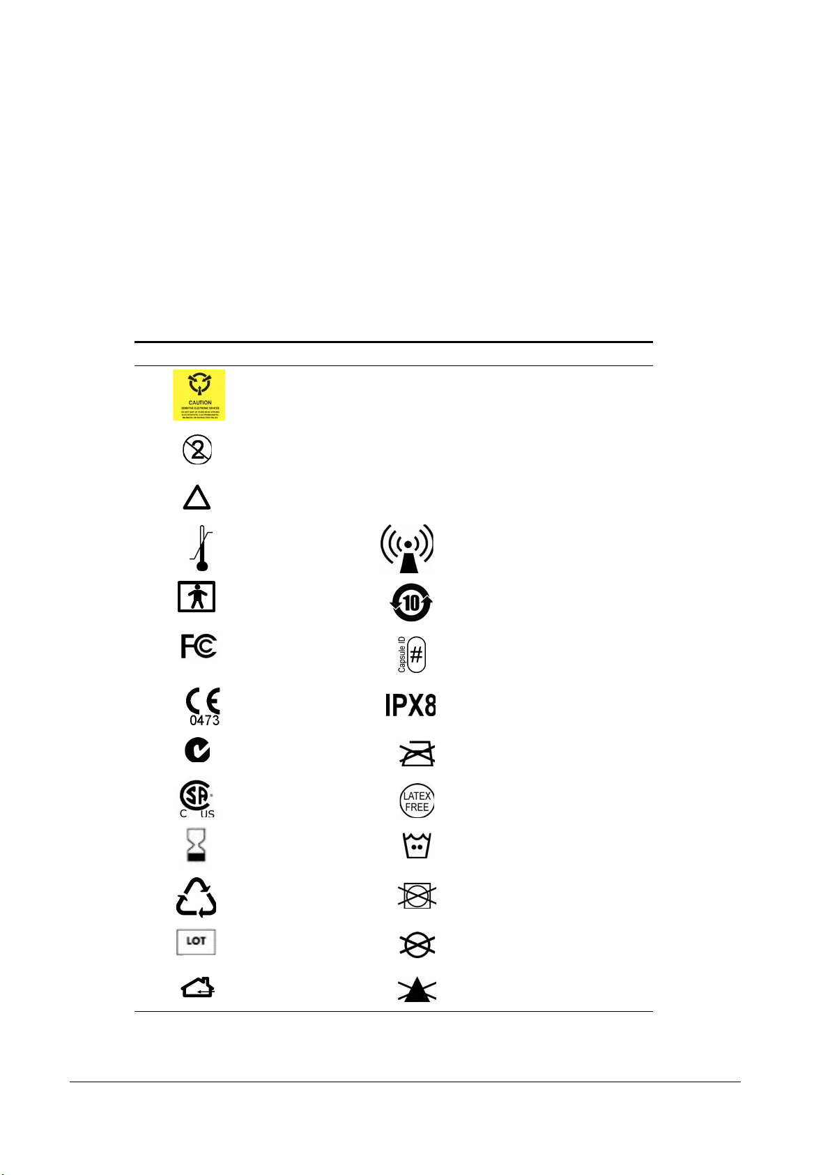
The following table lists the labels attached to various components of the PillCam Platform:
Labeling Explanation
Chapter 5
Technical Description
The PillCam video capsule should not be stored and used near any
powerful magnetic fields such as the one created by an MRI.
The PillCam video capsule is intended for single use only.
!
Attention! Consult the documentation provided with the PillCam
Platform.
Temperature
limits
Type BF
equipment
FCC compliance Capsule ID
CE mark Ingress protection
C-Tick mark Do not Iron
CSA mark Latex free
Expiration date Machine wash - warm
Non-ionizing radiation
RoHs
Recycle Do not tumble dry
Lot number Do not dry clean
Indoor use only Do not use bleach
Given Imaging Ltd. 35
Page 42
PillCam Platform
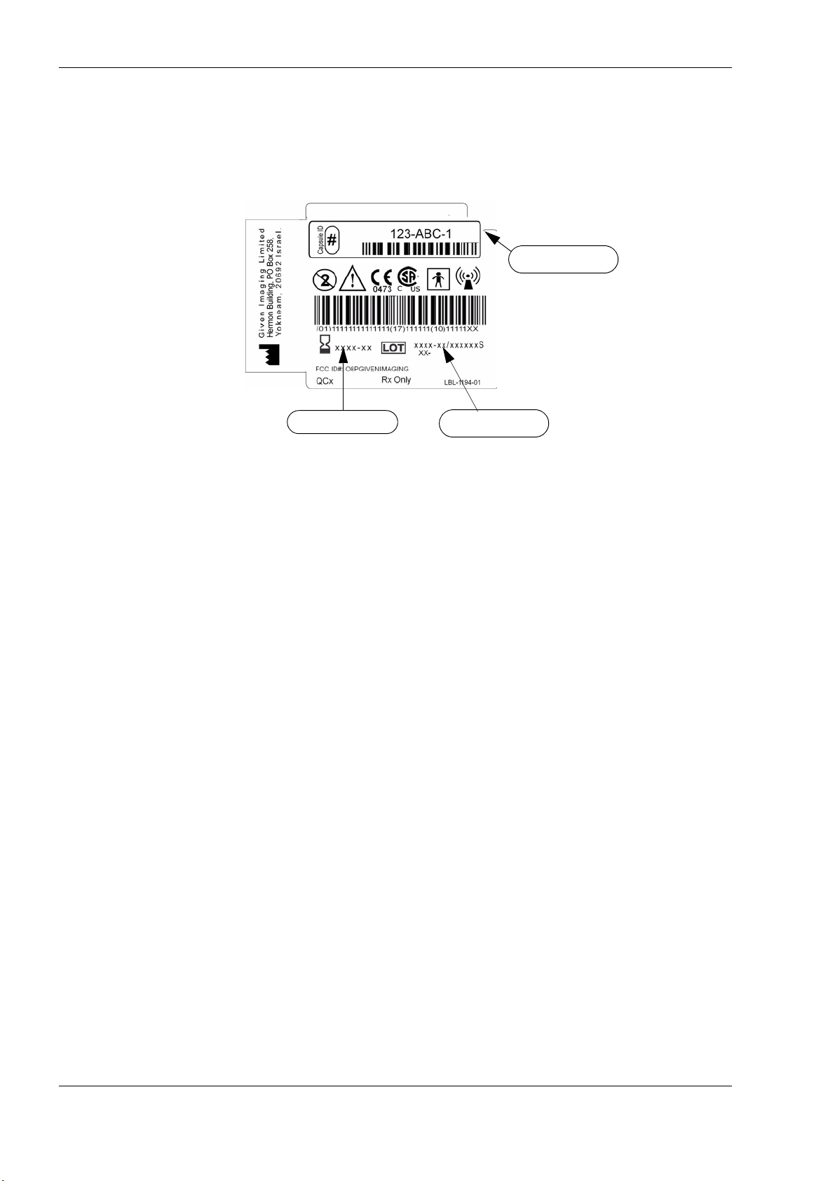
Lot Number
Expiration Date
Capsule ID Code
Capsule Labeling
Each box has a label at the bottom as shown below. Each capsule is marked with the expiration
date, lot number, and a unique Capsule ID code.
Essential Performance
PillCam Video Capsules
ON-Mode
Data transmitting to DataRecorder is considered to be essential performance of the PillCam
capsules. The PillCam capsules shall transmit data continuously monitored by on-line image
display as received by DataRecorder.
OFF-Mode
No unintentional transmissions are allowed.
DataRecorder 2 and DataRecorder 3
Data receiving by DataRecorder is considered to be essential performance of the DataRecorder 2
and DataRecorder 3.
Warnings
• PillCam Platform and its components need special precautions regarding EMC and need to be
installed and put into service according to the EMC information provided in the accompanying
documents.
• Portable and mobile RF communications equipment can affect the PillCam video capsule and
the DataRecorder.
36 Chapter 5
Page 43

Technical Description
• PillCam video capsules and DataRecorder should not be used adjacent to or stacked with other
equipment and that if adjacent or stacked use is necessary, the equipment or system should be
observed to verify normal operation in the configuration in which it will be used.
• PillCam video capsules and DataRecorder may be interfered with by other equipment, even if
that other equipment complies with CISPR emission requirements.
• Do not disassemble or modify the battery pack. The battery pack is equipped with built-in
safety/protection features. Should these features be disabled, the battery pack can leak acid,
overheat, emit smoke, burst and/or ignite.
• Do not use or leave the battery pack of the DataRecorder near a heat source such as a fire or a
heater (+80°C or higher). If the resin separator should be damaged owing to overheating,
internal short-circuiting may occur to the battery pack, possibly leading to acid leakage, smoke
emission, bursting and/or ignition of the battery pack.
• Do not immerse the battery pack in water or seawater and do not allow it to get wet.
Otherwise, the protective features in it can be damaged, it can be charged with extremely high
current and voltage, abnormal chemical reactions may occur in it, possibly leading to acid
leakage, smoke emission, bursting and/or ignition.
• Do not recharge the battery pack near fire or in extremely hot weather. Otherwise, hot
temperatures can trigger its built-in protective features, inhibiting recharging, or can damage
the built-in protective features, causing it to be charged with an extremely high current and
voltage and, as a result, abnormal chemical reactions can occur in it, possibly leading to acid
leakage, overheating, smoke emission, bursting and/or ignition.
• To recharge the battery pack, use the DataRecorder cradle and observe the recharging
conditions. A recharging operation under non-conforming recharging conditions (higher
temperature and larger voltage/current than specified, modified battery charger, etc.) can cause
the battery pack to be overcharged, or charged with extremely high current, abnormal
chemical reaction can occur in it, possibly leading to acid leakage, overheating, smoke
emission, bursting and/or ignition.
• Do not pierce the battery pack with a nail or other sharp objects, strike it with a hammer, or
step on it. Otherwise, the battery pack will become damaged and deformed, internal shortcircuiting can occur, possibly leading to acid leakage, overheating, smoke emission, bursting
and/or ignition.
• Do not strike or throw the battery pack. The impact might cause leakage, overheating, smoke
emission, bursting and/or ignition. Also, if the protective feature in it becomes damaged, it
could become charged with an extremely high current and voltage, abnormal chemical
reactions can occur, which can lead to acid leakage, overheating smoke emission, bursting
and/or ignition.
• Do not use an apparently damaged or deformed battery pack. Otherwise, acid leakage,
overheating, smoke emission, bursting and/or ignition of the battery pack may occur.
• If the battery pack leaks and the electrolyte gets into the eyes, do not rub them. Instead, rinse
the eyes with clean running water and immediately seek medical attention. Otherwise, eye
injury may result.
• If recharging operation fails to complete even when a specified recharging time has elapsed,
immediately stop further recharging. Otherwise, acid leakage, overheating, smoke emission,
bursting and/or ignition can occur.
• Do not put the battery pack into a microwave oven or pressurized container. Rapid heating or
disrupted sealing can lead to acid leakage, overheating, smoke emission, bursting and/or
ignition.
Chapter 5 37
Page 44

PillCam Platform
Note
• If the battery pack leaks or gives off a bad odor, remove it from any exposed flame. Otherwise,
the leaking electrolyte may catch fire and the battery pack may emit smoke, burst or ignite.
• If the battery pack gives off an odor, generates heat, becomes discolored or deformed, or in any
way appears abnormal during use, recharging or storage, immediately remove it from the
equipment or cradle and stop using it. Otherwise, the problematic battery pack can develop acid
leakage, overheating, smoke emission, bursting and/or ignition.
• The use of accessories, transducers and cables other than those supplied or approved by Given
Imaging as replacement parts for internal DataRecorder components, may result in increased
emissions or decreased immunity of the PillCam Platform.
Cautions
• Do not use or subject the battery pack to intense sunlight or hot temperatures such as in a car in
hot weather. Otherwise, acid leakage, overheating and/or smoke emission can occur. Also, its
guaranteed performance will be lost and/or its service life will be shortened.
• The battery pack incorporates built-in safety devices. Do not use it in a location where static
electricity (greater than the manufacturer’s guarantee) may be present. Otherwise, the safety
devices can be damaged, possibly leading to acid leakage, overheating, smoke emission,
bursting and/or ignition.
• The guaranteed recharging temperature range is 0°C to +45°C. A recharging operation outside
this temperature range can lead to acid leakage and/or overheating of the battery pack and may
cause damage to it.
• If acid leaking from the battery pack comes into contact with your skin or clothing, immediately
wash it away with running water. Otherwise, skin inflammation can occur.
• For recharging procedures, refer to DataRecorder 3 on page 66.
• If you find rust, a bad odor, overheating and/or other irregularities when using the battery pack
for the first time, return it to your supplier or vendor.
System Specifications
Specifications are subject to change without prior notice and without any
obligation to users on the part of the manufacturer.
38 Chapter 5
Page 45

PillCam SB Capsule
Properties
Physical Dimensions Length: 26 mm
Weight 3.30 gr
Material Biocompatible plastic
Optical Illumination 6 white light emitting diodes
# of imaging heads 1
Field of view 140° ISO-8600-3
Effective visibility Distance: 3 cm
Magnification 1:8
Min. detectable object Less than 0.1 mm
Operational Frame rate 2 fps
Technical Description
Diameter: 11 mm
Operating time 7 ± 1 hours
Chemical safety Resistant to dissolution in pH=2 to pH=8
Battery type Silver Oxide batteries
Operating temperature
Storage temperature
20–45
0–50
°C
°C
Chapter 5 39
Page 46

PillCam Platform
PillCam SB 2 Capsule
Properties
Physical Dimensions Length: 26 mm
Optical Illumination 4 white light emitting diodes
Operational Frame rate either 2 or 4 fps
Diameter: 11 mm
Weight 2.89gr.
Material Biocompatible plastic
# of imaging heads 1
Field of view 156° ISO-8600-3
Effective visibility Distance: 3 cm
Min. detectable object Less than 0.1 mm
Operating time >
Chemical safety Resistant to dissolution in pH=2 to pH=8
Battery type Silver Oxide batteries (3V)
Operating temperature
Storage temperature
8 hours
20–45
0–40
°C
°C
40 Chapter 5
Page 47

PillCam ESO 2 Capsule
Properties
Physical Dimensions Length: 26 mm
Weight 2.89 gr
Material Biocompatible plastic
Optical Illumination 4 white light emitting diodes for each head
# of imaging heads 2
Technical Description
Diameter: 11 mm
Field of view
Effective visibility Distance: 3 cm
Min. detectable object Less than 0.06 mm
Operational Frame rate up to 9 fps per head
Operating time 30 minutes
Chemical safety Resistant to dissolution in pH=2 to pH=8
Battery type Silver Oxide batteries
Operating temperature
Storage temperature
° ISO-8600-3
169
°C
20–45
0–50
°C
for each head
Chapter 5 41
Page 48

PillCam Platform
PillCam ESO 3 Capsule
Properties
Physical Dimensions
Optical Illumination 4 white light emitting diodes for each head
Length: 31.5 mm
Diameter: 11.6 mm
Weight 2.9 gr
Material Biocompatible plastic
# of optical heads 2
Field of view
Effective visibility Distance: 0–30 mm
Min. detectable object 0.09 mm
Operational Frame rate 35 fps per head
Operating time 30 minutes
Chemical safety Resistant to dissolution in pH=2 to pH=8
Battery type Silver Oxide batteries
Operating temperature
Storage temperature
172° ISO-8600-3
°C
20–45
°C
0–40
for each head
42 Chapter 5
Page 49

PillCam COLON 2 Capsule
Properties
Physical Dimensions Length: 31.5 mm
Weight 2.9 g
Material Biocompatible pl astic
Optical # of optical heads 2
Illumination 4 white light emitting diodes on each side
Field of view 172° ISO-8600-3
Effective visibility Distance: 0–30 mm
Min. detectable
object
Operational Operating time Total: 10 hours:
Chemical safety Resistant to dissolution in pH=2 to pH=8
Technical Description
Diameter: 11.6 mm
0.09 mm
Uplink
communication
Downlink
communication
Battery type Silver Oxide batteries
Operating
temperature
Storage temperature
Operating frequency 434.1 MHz
Frame rate 4–35 fps
Data rate 2.7 Mbps and 8.1 Mbps
Modulation type MSK/Digital data
Frequency band
standards
Effective radiated
power
Operating frequency 13.56 MHz
Receiver Bandwidth +
Frequency band
standards
°C
20–45
0–30
°C
FCC CFR 47 part 15 section 15.209
ERC 70-03 Annex 1 band F1
-48.8 dBm (measured in 120 kHz bandwidth)
150 KHz
FCC CFR 47 part 15 section 15.225
ERC 70-03 Annex 9 band F
Chapter 5 43
Page 50

PillCam Platform
SensorArray DataRecorder 2
Versions: SB, COLON, ESO
Sensor size Diameter 40 mm
Color black
Material plastic
SB = COLON
SensorArray
ESO
SensorArray
SensorArray DataRecorder 3
Properties
Reception antenna # of sensor elements 3 or 8 sensors
8 sensor elements
3 sensor elements
Sensor size Diameter: 40 mm
Color Black
Material Polyurethane, Teflon
Antennas wire material Coax wire
Transmission antenna Antenna structure Loop antenna
Size 1.90 m
Color Black
Material Polyurethane, Teflon
44 Chapter 5
Page 51

Technical Description
SB SensorBelt for DataRecorder 2 and DataRecorder 3
SensorBelt Insert
Dimensions 365 mm x 90 mm
Insert material Polypropylene
Number of sensors 4
Sensor dimensions Diameter 40 mm
Cable length 550 mm
Cleaning method Wipe with medical alcohol wipes
Expected life 500 procedures
SensorBelt Cover and Straps
Cover dimensions 385 mm x 125 mm
Cover and strap material 100% polyester
Fits abdomen size 60 - 130 cm
Washing instructions
Expected life 40 wash cycles
DataRecorder 2 /2C
Software Proprietary firmware
Recording capacity DataRecorder 2: @2fps for 10 hours
Weight 500 gr., including battery pack.
Operational Power 6–8 VDC, 0.1–0.3 A
Battery type Internal, Li-Ion, 7.2 V, 4400 mAH
Battery Pack weight 200 gr.
Operating temp.
Storage temp.
Shielding Shieldex Supra, from Less EMF Inc.
Classification • internally powered (complies with requirements for
Machine wash, warm, Use mild detergent
Hang dry
Do not dry clean, Do not use bleach
DataRecorder 2C: @4fps for 10 hours
0–40
°C
°C
0–55
Class I equipment while connected to supply mains
through charger)
• Type BF applied part
• Ordinary equipment
Chapter 5 45
Page 52

PillCam Platform
Cradle DataRecorder 2
Properties
Weight 890 g
Size (without
battery inserter
Color black
Mains power
connections
power mains
range
DataRecorder 3
Properties
Physical Software Proprietary firmware
14[D] x 165[W] x 97[H]mm
1x male power cable plug
100 to 240V
Recording capacity Up to 15 hours @ LCD OFF
Weight 500 g., including battery pack.
Operational Power 3.5–4.2 VDC, 0.15–0.5 A
Battery type Internal, Li-Ion, 3.8 V typical, 8800
mAH
Operating temp.
Storage temp.
0–40
0–55
°C
°C
Shielding No belt shielding
Classification • internally powered (comp lies
with requirements for Class I
equipment while connected to
supply mains through charger)
• Type BF applied part
• Ordinary equipment
Receiver (Rx) Operating frequency 434.1 MHz
Bandwidth of the receiving
section in this band
Transmitter Operating frequency 13.56 MHz
Frequency band ISM
Modulation type Linear Chirp
Type of modulated signal Digital data
Frequency of modulating
signal
Effective radiated power -27.4 dBm
10 MHz
20.25 dBm
46 Chapter 5
Page 53

Cradle DataRecorder 3
Properties
Weight 250 g
Technical Description
Operating temp
Color White & Black
Mains power
connections
power mains range
DC Power Supply
Properties
Weight 300 g
Input connector 3 pole AC inlet IEC320-C14C
Input Voltage 90 - 246 VAC
Output voltage 5V DC, 5 Amp
Protections
0–45
°C
1x male power cable plug
Input Voltage: Maximum 5.25V, Min 4.75V
Input Current: Maximum 4A, Min 100 mA
Short circuit/ Over load/ Over voltage/
Over temp.
DataRecorder 3 Memory Card
Properties
Dimensions 24mm x 32mm x 2.1mm
Weight
Capacity
Rating
Storage
temperature
Security
Compatibility
File format
2.5 g
16GB
>
Class 6: 40X or higher,
6 MB/sec minimum data transfer rate
-40
°C–85°C
Built-in write-protect switch prevents
accidental data loss
SDHC host devices; not compatible with
standard SD-enabled devices/readers
FAT 32
Chapter 5 47
Page 54

PillCam Platform
RAPID Software
Software RAPID proprietary, version 7
Languages English/French/German/Italian/Spanish/Portuguese/Dutch/
Data export JPEG Images, (AVI) Video clips, grml (Given proprietary) files,
Displayed data Single and multi images, Timebar, Colorbar with region specific
Event marker Annotated thumbnails
Viewing rate 5–80 fps
Viewing Modes SingleView, DualView, QuadView, Mosaic View, Double-Head
Run Modes Normal, QuickView, SBI
Swedish/Finnish/Danish/Chinese-Mandarin/Korean/Russian/
Greek
HTML Reports, generic XML-format Capsule Endoscopy report
data.
color and other diagnostic data.
View (ESO and COLON)
Guidance and Manufacturer's Declarations
PillCam Capsules (No PillCam COLON 2)
Guidance and manufacturer’s declaration - electronic emissions
The PillCam capsules are intended for use in the electromagnetic environment specified below. The
customer or the user of the PillCam capsules capsule should assure that it is us ed in such an
environment.
Emissions test Compliance Electromagnetic environment - guidance
The PillCam capsules use RF energy only for its
RF emissions
CISPR 11
RF emissions
CISPR 11
Harmonic emissions
IEC 61000-3-2
Voltage fluctuat io ns/
flicker emissions
IEC 61000-3-3
Group 1
Class B
Not applicable
Not applicable
internal function. Therefore, its RF emissions are very
low and are not likely to cause any interference in
nearby electronic equipment
The PillCam capsules are suitable for use in all
establishments including domestic establishments and
those directly connected to the public low-voltage
power supply network that supplies buildings used for
domestic purposes.
48 Chapter 5
Page 55

Technical Description
Guidance and manufacturer’s declaration - electronic emissions
The PillCam capsules are intended for use in the electromagnetic envi ronment specified below. The
customer or the user of the PillCam capsules should assure that it is used in such an environment.
Immunity test
IEC 60601 test
level
Compliance
level
Electromagnetic
environment - guidance
Electrostatic discharge
(ESD)
IEC 61000-4-2
Electrical fast transient
/ burst
IEC 61000-4-4
Surge,
IEC 61000-4-5
Voltage dips, short
interruptions and
voltage variations on
power supply input
lines
IEC 61000-4-11
±6 kV contact
±8 kV air
±2 kV for power supply
lines
±1 kV for input/output
lines
±1 kV line(s) to line(s)
±2 kV line(s) to earth
<5 % U
(>95 % dip in U
T
)
T
for 0.5 cycle
40 % U
(60 % dip in U
T
)
T
for 5 cycles
70 % U
T
(30 % dip in UT)
for 25 cycles
<5 % U
(>95 % dip in U
T
)
T
for 5 sec
±6 kV contact
±8 kV air
Floors should be wood, concrete or
ceramic tile. If floors are covered with
synthetic material, the relative
humidity should be at least 30 %.
Not applicable Not applicable
Not applicable Not applicable
Not applicable Not applicable
Power frequency (50/
60 Hz) magnetic field,
3 A/m 3 A/m
IEC 61000-4-8
NOTE: U
Chapter 5 49
is the AC mains voltage prior to application of the test level.
T
Power frequency magnetic fields
should be at levels characteristic of a
typical location in a typical commercial
or hospital environment.
Page 56
PillCam Platform
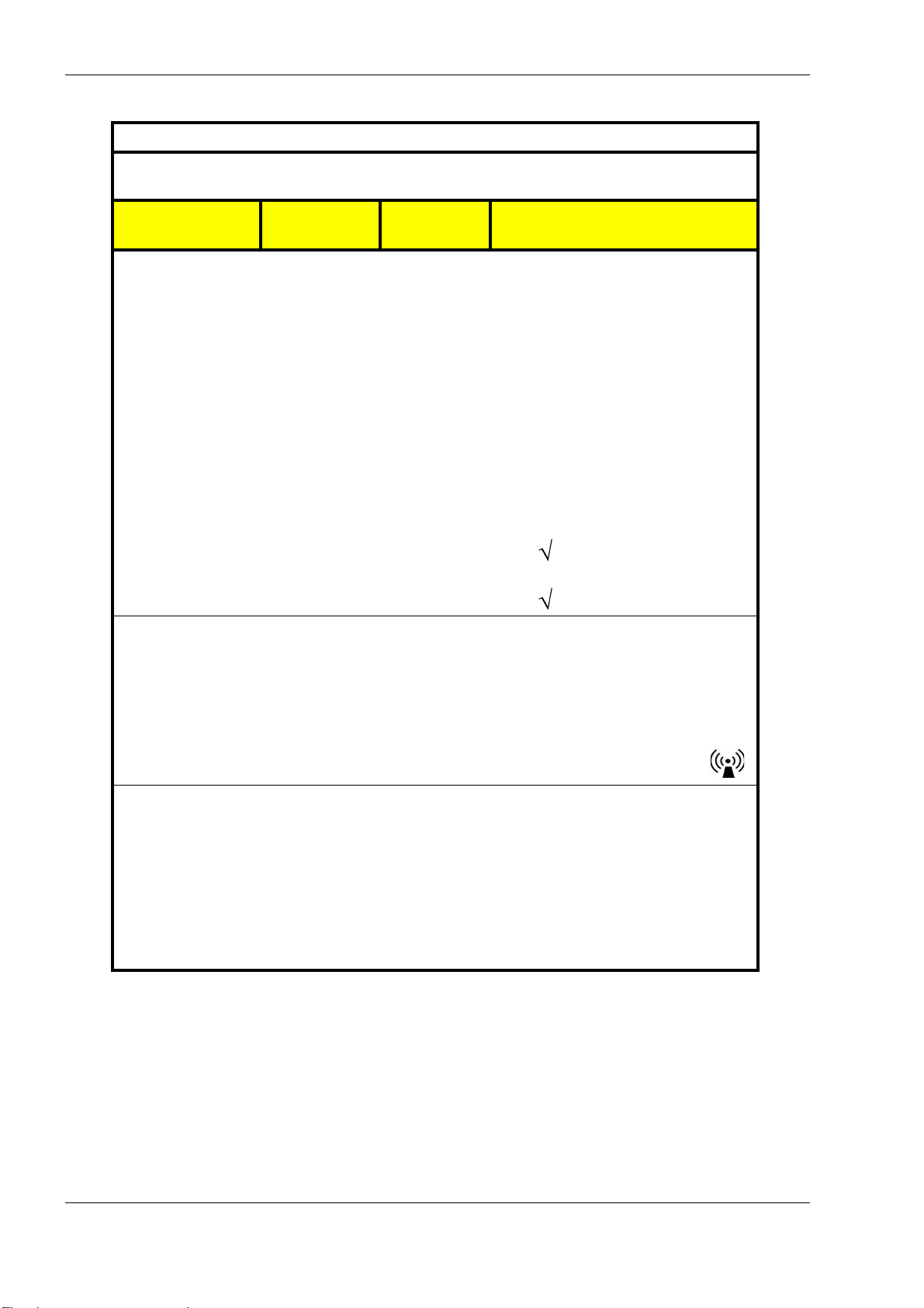
The PillCam capsules are intended for use in the electromag netic environment specified below. The
customer or the user of the PillCam capsules should assure that it is used in such an environment.
Immunity test
Guidance and manufacturer’s declaration - electronic emissions
IEC 60601 test
level
Compliance
level
Electromagnetic environment -
guidance
Portable and mobile RF communications
equipment should be used no closer to
any part of a PillCam capsule, including
cables, than the recommended separation
distance calculated from the equation
applicable to the frequency of the
transmitter.
Recommended separation distance
Conducted RF
IEC 61000-4-6
Radiated RF
IEC 61000-4-3
3 VRMS
150 kHz to
80 MHz
3 V/m
80 MHz to
2.5 GHz
Not applicable Not applicable
d = 1.2 P 80 MHz to 800 MHz
3 V/m
d = 2.3 P 800 MHz to 2.5 GHz
NOTE 1: At 80 MHz and 800 MHz, the higher frequency range applies.
NOTE 2: These guidelines may not apply in all situations. Electromagne tic propagation is affected by
absorption and reflection from structures, objects and people.
NOTE 3: P is the maximum output power rating of the transmitter in watts (W) according to the
transmitter manufacturer and d is the recommended separation distance in meters (m).
NOTE 4: Field strengths from fixed RF transmitters, as determined by an electromagnetic site survey
b
should be less than the compliance level in each frequency range
.
a
NOTE 5: Interference may occur in the vicinity of equipment marked with the following symbol:
a Field strengths from fixed transmitters, such as base stations for radio (cellular/cordless) telephones
and land mobile radios, amateur radio, AM and FM radio broadcast and TV broadcast cannot be
predicted theoretically with accuracy. To assess the electromagnetic environment due to fixed RF
transmitters, an electromagnetic site survey should be considered. If the measured field strength in
the location in which the PillCam capsules are used exceeds th e applicable RF compliance level
above, the PillCam capsules should be observed to verify normal operation. If abnormal
performance is observed, additional measures may be necessary, such as re-orienting or relocating
the PillCam capsules.
b Over the frequency range 150 kHz to 80 MHz, field strengths should be less than 3 V/m.
,
50 Chapter 5
Page 57

Technical Description
Recommended separation distances between portable and mobile RF
communications equipment and the PillCam capsules
The PillCam capsules are intended for use in an electromagne tic environment in which radiated RF
disturbances are controlled. The customer or the user of the PillCam capsules can help prevent
electromagnetic interference by maintaining a minimum distance be tween portable and mobile RF
communications equipment (transmitters) and the PillCam capsules as recommended below, according to
the maximum output power of the communications equipment.
Separation distance according to frequency of transmitter [m]
Rated maximum
output power of
transmitter [W]
0.01 Not applicable 0.12 0.23
0.1 Not applicable 0.38 0.73
1 Not applicable 1.2 2.3
10 Not applicable 3. 8 7.3
150 kHz to 80 MHz
d = 1.2 P
80 MHz to 800 MHz
d = 1.2 P
800 MHz to 2,5 GHz
d = 2.3 P
100 Not applicable 12 23
For transmitters rated at a maximum output power not listed above, the recommended separation distance
d in meters (m) can be determined using the equation applicable to the frequency of the transmitter, where
P is the maximum output power rating of the transmitter in watts (W) according to the transmitter
manufacturer.
NOTE 1: At 80 MHz and 800 MHz, the separation distance for the higher frequency range applies.
NOTE 2: These guidelines may not apply in all situations. Electromagnetic propagation is affected by
absorption and reflection from structures, objects and people.
PillCam COLON 2 Capsules
Guidance and manufacturer’s declaration - electromagnetic emissions
The PillCam COLON 2 capsules are intended for use in the electromagnetic environment specified below.
The customer or the user of the PillCam COLON 2 capsules capsule should assure that it is used in such
an environment.
Emissions test Compliance Electromagnetic environment - guidance
The PillCam COLON 2 capsules use RF energy only
RF emissions
CISPR 11
Group 1
for its internal function. Therefore, its RF emissions
are very low and are not likely to cause any
interference in nearby electronic equipment
RF emissions
CISPR 11
Harmonic emissions
IEC 61000-3-2
Voltage fluctuations/
flicker emissions
IEC 61000-3-3
Chapter 5 51
Class B
Not applicable
Not applicable
The PillCam capsules are suitable for use in all
establishments including domestic establishments and
those directly connected to the public low-voltage
power supply network that supplies buildings used for
domestic purposes.
Page 58

PillCam Platform
Guidance and manufacturer’s declaration - electromagnetic immunity for all
equipment and systems
The PillCam COLON 2 capsules are intended for use in the electromagnetic environment specified below.
The customer or the user of the PillCam COLON 2 capsules should assure that it is used in such an
environment.
Immunity test
IEC 60601 test
level
Compliance
level
Electromagnetic
environment - guidance
Electrostatic discharge
(ESD)
IEC 61000-4-2
Electrical fast transient
/ burst
IEC 61000-4-4
Surge,
IEC 61000-4-5
Voltage dips, short
interruptions and
voltage variations on
power supply input
lines
IEC 61000-4-11
±6 kV contact
±8 kV air
±2 kV for power supply
lines
±1 kV for input/output
lines
±1 kV line(s) to line(s)
±2 kV line(s) to earth
<5 % U
(>95 % dip in U
T
)
T
for 0.5 cycle
40 % U
(60 % dip in U
T
)
T
for 5 cycles
70 % U
T
(30 % dip in UT)
for 25 cycles
<5 % U
(>95 % dip in U
T
)
T
for 5 sec
±6 kV contact
±8 kV air
Not applicable
Not applicable
Not applicable
Floors should be wood, concrete or
ceramic tile. If floors are covered with
synthetic material, the relative
humidity should be at least 30 %.
Mains power quality should be that of
a typical commercial or hospital
environment.
Mains power quality should be that of
a typical commercial or hospital
environment.
Mains power quality should be that of
a typical commercial or hospital
environment. If the user of the
equipment requires continued
operation during power mains
interruptions, it is recommended that
the equipment be powered from an
uninterruptible power supply or a
battery.
Power frequency (50/
60 Hz) magnetic field,
3 A/m 3 A/m
IEC 61000-4-8
NOTE: U
52 Chapter 5
is the AC mains voltage prior to application of the test level.
T
Power frequency magnetic fields
should be at levels characteristic of a
typical location in a typical commercial
or hospital environment.
Page 59
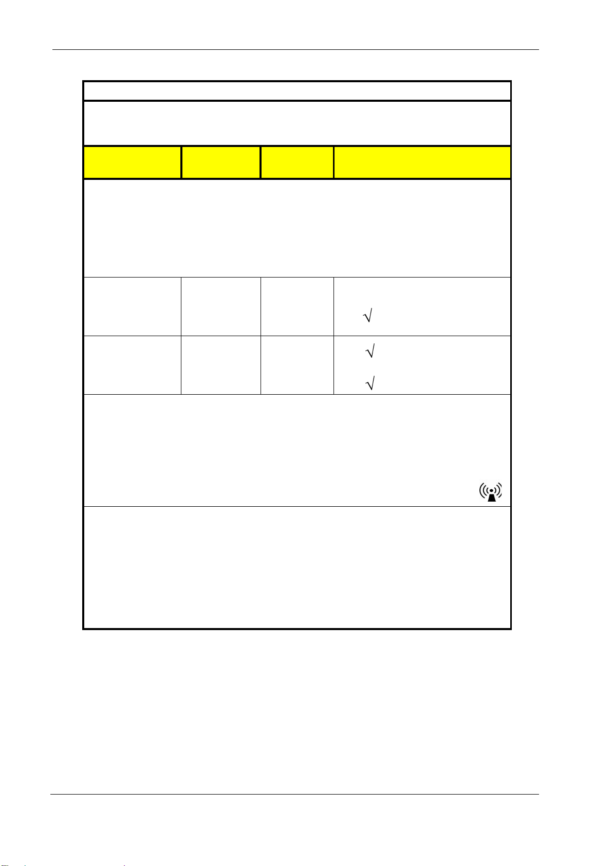
Technical Description
Guidance and manufacturer’s declaration - electromagnetic immunity
The PillCam COLON 2 capsules are intended for use in the electromagnetic environment specified
below. The customer or the user of the PillCam capsules should assure that it is used in such an
environment.
Immunity test
IEC 60601 test
level
Compliance
level
Electromagnetic environment -
guidance
Portable and mobile RF communications
equipment should be used no closer to
any part of a PillCam capsule, including
cables, than the recommended separation
distance calculated from the equation
applicable to the frequency of the
transmitter.
Conducted RF
IEC 61000-4-6
Radiated RF
IEC 61000-4-3
3 Vrms
150 kHz to
80 MHz
3 V/m
80 MHz to
2.5 GHz
Not applicable
3 V/m
Recommended separation distance:
d= 1.2 P
d = 1.2 P 80 MHz to 800 MHz
MHz range
d = 2.3 P 800 MHz to 2500 MHz
NOTE 1: At 80 MHz and 800 MHz, the higher frequency range appl ies.
NOTE 2: These guidelines may not apply in all situations. Electromagnetic propagation is affected by
absorption and reflection from structures, objects and people.
NOTE 3: P is the maximum output power rating of the transmitter in watts (W) according to the
transmitter manufacturer and d is the recommended separation distance in meters (m).
NOTE 4: Field strengths from fixed RF transmitters, as determined by an electromagnetic site survey
b
should be less than the compliance level in each frequency range
.
NOTE 5: Interference may occur in the vicinity of equipment marked with the following symbol:
a Field strengths from fixed transmitters, such as base stations for radio (cellular/cordless) telephones
and land mobile radios, amateur radio, AM and FM radio broadcast a nd TV broadcast cannot be
predicted theoretically with accuracy. To asses s the electromagnetic environment due to fixed RF
transmitters, an electromagnetic site survey should be considered. If the measured field strength in
the location in which the PillCam capsules are used exceeds the applicable RF compliance leve l
above, the PillCam capsules should be observed to verify normal operation. If abnormal
performance is observed, additional measures may be necessary, such as re-orienting or relocating
the PillCam capsules.
b Over the frequency range 150 kHz to 80 MHz, field strengths should be less than 3 V/m.
a
,
Chapter 5 53
Page 60

PillCam Platform
Recommended separation distances between portable and mobile RF
communications equipment and the PillCam COLON 2 capsules
The PillCam COLON 2 capsules are intended for use in an electromagne tic environment in which radiated
RF disturbances are controlled. The customer or the user of the PillCam COLON 2 capsules can help
prevent electromagnetic interference by maintaining a minimum distance between p ortable and mobile RF
communications equipment (transmitters) and the PillCam COLON 2 capsules as recommended below,
according to the maximum output power of the communications equipment.
Separation distance according to frequency of transmitter [m]
Rated maximum
output power of
150 kHz to 80 MHz
80 MHz to 800 MHz
800 MHz to 2,5 GHz
transmitter [W]
d = 1.2 P
d = 1.2 P
d = 2.3 P
0.01 0.12 0.12 0.23
0.1 0.38 0.38 0.73
11.2 1.2 2.3
10 3.8 3.8 7.3
100121223
For transmitters rated at a maximum output power not listed above, the recommended separation distance
d in meters (m) can be determined using the equation applicable to the frequency of the transmitter, where
P is the maximum output power rating of the transmitter in watts (W) according to the transmitter
manufacturer.
NOTE 1: At 80 MHz and 800 MHz, the separation distance for the higher frequency range applies.
NOTE 2: These guidelines may not apply in all situations. Electromagne tic propagation is affected by
absorption and reflection from structures, objects and people.
54 Chapter 5
Page 61

Technical Description
DataRecorder 2(C)
Guidance and manufacturer’s declaration - electronic emissions
The DataRecorder 2 is intended for use in the electromagne tic environment specified below. The
customer or the user of the DataRecorder 2 should assure that it is used in such an environment.
Emissions test Compliance Electromagnetic environment - guidance
The DataRecorder 2 uses RF energy only for its
RF emissions
CISPR 11
Group 1
internal function. Therefore, its RF emissions are very
low and are not likely to cause any interference in
nearby electronic equipment
RF emissions
CISPR 11
Harmonic emissions
IEC 61000-3-2
Voltage fluctuations/
flicker emissions
IEC 61000-3-3
Guidance and manufacturer’s declaration - electronic emissions
The DataRecorder 2 is intended for use in the electromagnetic environment specified below. The customer
or the user of the DataRecorder 2 should assure that it is used in such an environment.
Immunity test IEC 60601 test level Compliance level
Electrostatic
discharge (ESD)
IEC 61000-4-2
±6 kV contact
±8 kV air
Class B
Class A
Complies
The DataRecorder 2 is suitable for use in all
establishments including domestic establishments and
those directly connected to the public low-voltage
power supply network that supplies buildings used for
domestic purposes.
Electromagnetic
environment -
guidance
Floors should be wood,
±6 kV contact
±8 kV air
concrete or ceramic tile. If
floors are covered with
synthetic material, the relative
humidity should be at least
30%.
Electrical fast
transient / burst
IEC 61000-4-4
Surge,
IEC 61000-4-5
Chapter 5 55
±2 kV for power supply
lines
±1 kV for input/output lines
±1 kV line(s) to line(s)
±2 kV line(s) to earth
±2 kV for power supply
lines
±1 kV for input/output lines
±1 kV line(s) to line(s)
±2 kV line(s) to earth
Mains power quality should be
that of a typical commercial or
hospital environment.
Mains power quality should be
that of a typical commercial or
hospital environment.
Page 62
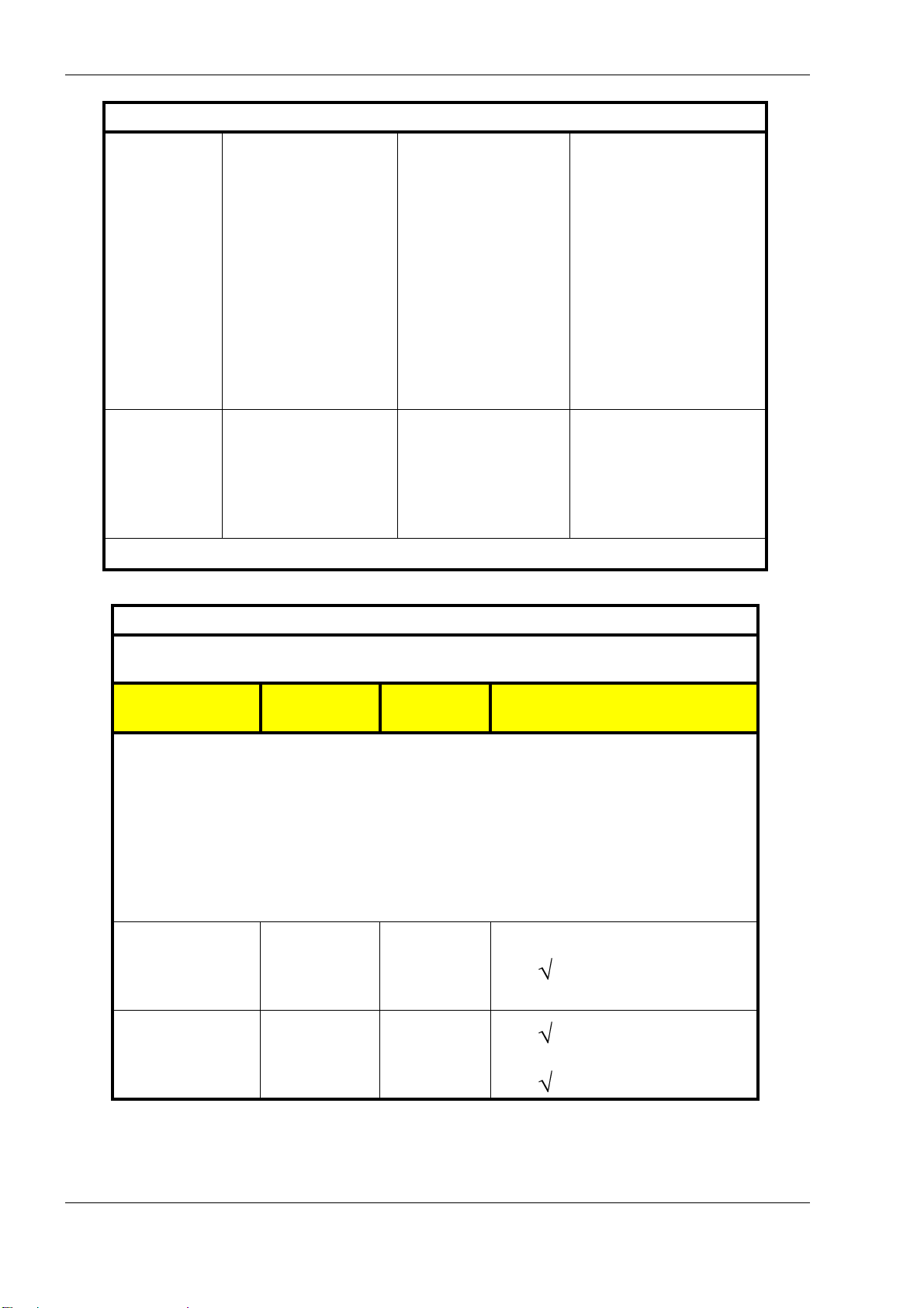
PillCam Platform
Guidance and manufacturer’s declaration - electronic emissions
Voltage dips,
short interruptions
and voltage
variations on
power supply
input lines
IEC 61000-4-11
Power frequency
(50/60 Hz)
magnetic field,
IEC 61000-4-8
NOTE: U
is the AC mains voltage prior to application of the test level.
T
<5 % U
T
(>95 % dip in U
for 0.5 cycle
40 % U
(60 % dip in U
T
T
for 5 cycles
70 % U
T
(30 % dip in UT)
for 25 cycles
<5 % U
T
(>95 % dip in U
for 5 sec
)
T
)
)
T
<5 % U
(>95 % dip in U
for 0.5 cycle
40 % U
(60 % dip in U
for 5 cycles
70 % U
(30 % dip in UT)
for 25 cycles
<5 % U
(>95 % dip in U
for 5 sec
3 A/m 3 A/m
T
)
T
Mains power quality should be
that of a typical commercial or
T
)
T
hospital environment. If the
user of the DataRecorder 2
requires continued operation
during power mains
T
interruptions, it is
recommended that the
DataRecorder 2 be powered
T
)
T
from an uninterruptible power
supply or a battery.
Power frequency magnetic
fields should be at levels
characteristic of a typical
location in a typical
commercial or hospital
environment.
Guidance and manufacturer’s declaration - electronic emissions
The DataRecorder 2 is intended for use in the electromagnetic environment specified below. The
customer or the user of the DataRecorder 2 should assure that it is used in such an environment.
Immunity test
IEC 60601 test
level
Compliance
level
Electromagnetic environment -
guidance
Portable and mobile RF communications
equipment should be used no closer to
any part of DataRecorder 2, including
cables, than the recommended separation
distance calculated from the equation
applicable to the frequency of the
transmitter.
Recommended separation distance
Conducted RF
IEC 61000-4-6
3 VRMS
150 kHz to
3V
ms
d = 1.2 P
80 MHz
Radiated RF
IEC 61000-4-3
3 V/m
80 MHz to
2.5 GHz
3 V/m
d = 1.2 P 80 MHz to 800 MHz range
d = 2.3 P 800 MHz to 2.5 GHz range
56 Chapter 5
Page 63
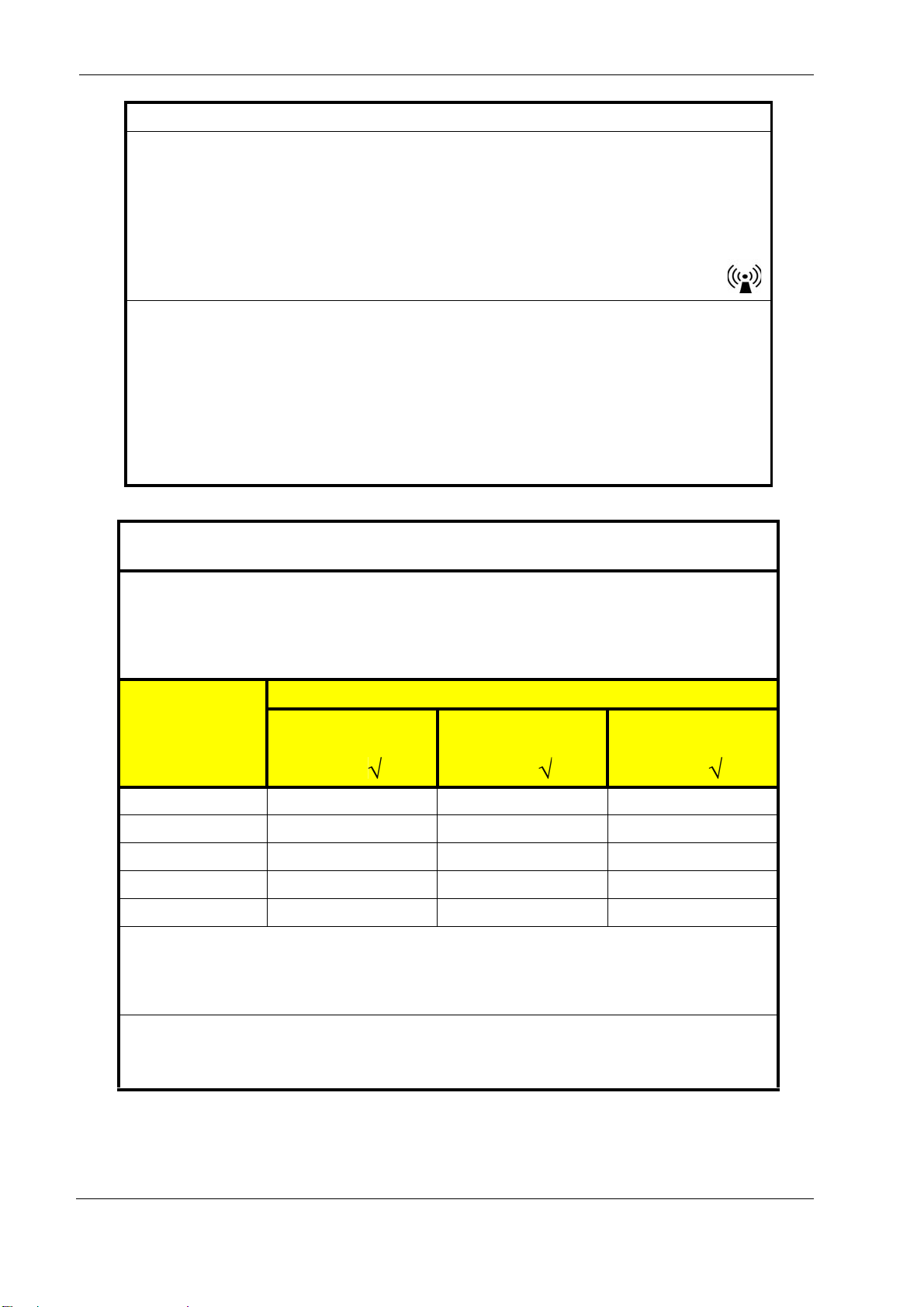
Technical Description
Guidance and manufacturer’s declaration - electronic emissions
NOTE 1: At 80 MHz and 800 MHz, the higher frequency range appl ies.
NOTE 2: These guidelines may not apply in all situations. Electromagnetic propagation is affected by
absorption and reflection from structures, objects and people.
NOTE 3: P is the maximum output power rating of the transmitter in watts (W) according to the
transmitter manufacturer and d is the recommended separation distance in meters (m).
NOTE 4: Field strengths from fixed RF transmitters, as determined by an electromagnetic site survey
b
should be less than the compliance level in each frequency range
.
NOTE 5: Interference may occur in the vicinity of equipment marked with the following symbol:
a Field strengths from fixed transmitters, such as base stations for radio (cellular/cordless) telephones
and land mobile radios, amateur radio, AM and FM radio broadcast a nd TV broadcast cannot be
predicted theoretically with accuracy. To asses s the electromagnetic environment due to fixed RF
transmitters, an electromagnetic site survey should be considered. If the measured field strength in
the location in which the DataRecorder 2 is used exceeds the applicable RF compliance level
above, the DataRecorder 2 should be observed to verify normal operation. If abnormal performance
is observed, additional measures may be necessary, such as re-orienting or relocating the
DataRecorder 2.
b Over the frequency range 150 kHz to 80 MHz, field strengths should be less than 3 V/m.
a
,
Recommended separation distances between portable and mobile RF
communications equipment and the PillCam ESO capsule
The DataRecorder 2 is intended for use in an electromagnetic environm ent in which radiated RF
disturbances are controlled. The customer or the user of the DataRecorder 2 can help prevent
electromagnetic interference by maintaining a minimum distance be tween portable and mobile RF
communications equipment (transmitters) and the DataRecorder 2 as recommended below, according to
the maximum output power of the communications equipment.
Separation distance according to frequency of transmitter [m]
Rated maximum
output power of
150 kHz to 80 MHz
80 MHz to 800 MHz
800 MHz to 2,5 GHz
transmitter [W]
d = 1.2 P
d = 1.2 P
d = 2.3 P
0.01 Not applicable 0.12 0.23
0.1 Not applicable 0.38 0.73
1 Not applicable 1.2 2.3
10 Not applicable 3. 8 7.3
100 Not applicable 12 23
For transmitters rated at a maximum output power not listed above, the recommended separation distance
d in meters (m) can be determined using the equation applicable to the frequency of the transmitter, where
P is the maximum output power rating of the transmitter in watts (W) according to the transmitter
manufacturer.
NOTE 1: At 80 MHz and 800 MHz, the separation distance for the higher frequency range applies.
NOTE 2: These guidelines may not apply in all situations. Electromagnetic propagation is affected by
absorption and reflection from structures, objects and people.
Chapter 5 57
Page 64

PillCam Platform
DataRecorder 3
Guidance and manufacturer’s declaration - electromagnetic emissions
The DataRecorder 3 is intended for use in the electromagnetic environment specified below. The
customer or the user of the DataRecorder 3 should assure that it is used in such an enviro nment.
Emissions test Compliance Electromagnetic environment - guidance
The Data Recorder 3 uses RF energy only for its
RF emissions
CISPR 11
Group 1
internal function. Therefore, its RF emissions are very
low and are not likely to cause any interference in
nearby electronic equipment
RF emissions
CISPR 11
Harmonic emissions
IEC 61000-3-2
Voltage fluctuat io ns/
flicker emissions
IEC 61000-3-3
Guidance and manufacturer’s declaration - electromagnetic immunity for all
The DataRecorder 3 is intended for use in the electromagnetic environment specified below. The customer
or the user of the DataRecorder 3 should assure that it is used in such an environment.
Immunity test IEC 60601 test level Compliance level
Electrostatic
discharge (ESD)
IEC 61000-4-2
6 kV contact
8 kV air
Class B
N/A
N/A
The Data Recorder 3 is suitable for use in all
establishments, including domestic establishments
and those directly connected to the public low-voltage
power supply network that supplies buildings used for
domestic purposes.
equipment and systems
6 kV contact
8 kV air
Electromagnetic
environment -
guidance
Floors should be wood,
concrete or ceramic tile. If
floors are covered with
synthetic material, the relative
humidity should be at least
30 %.
Electrical fast
transient / burst
IEC 61000-4-4
Surge,
IEC 61000-4-5
58 Chapter 5
2 kV for power supply lines
1 kV for input/output lines
1 kV line to line
2 kV line to earth
N/A
N/A
Mains power quality should be
that of a typical commercial or
hospital environment.
Mains power quality should be
that of a typical commercial or
hospital environment.
Page 65

Technical Description
Guidance and manufacturer’s declaration - electromagnetic immunity for all
equipment and systems
Voltage dips,
short interruptions
and voltage
variations on
power supply
input lines
IEC 61000-4-11
Power frequency
(50/60 Hz)
magnetic field,
IEC 61000-4-8
NOTE: U
is the AC mains voltage prior to application of the test level.
T
<5 % U
(>95 % dip in U
T
)
T
for 0.5 cycle
40 % U
(60 % dip in U
T
)
T
for 5 cycles
N/A
70 % U
T
(30 % dip in UT)
for 25 cycles
<5 % U
(>95 % dip in U
T
)
T
for 5 sec
3 A/m 3 A/m
Mains power quality should be
that of a typical commercial or
hospital environment. If the
user of the DataRecorder 3
requires continued operation
during power mains
interruptions, it is
recommended that the
DataRecorder 3 be powered
from an uninterruptible power
supply or a battery.
Power frequency magnetic
fields should be at levels
characteristic of a typical
location in a typical
commercial or hospital
environment.
Chapter 5 59
Page 66
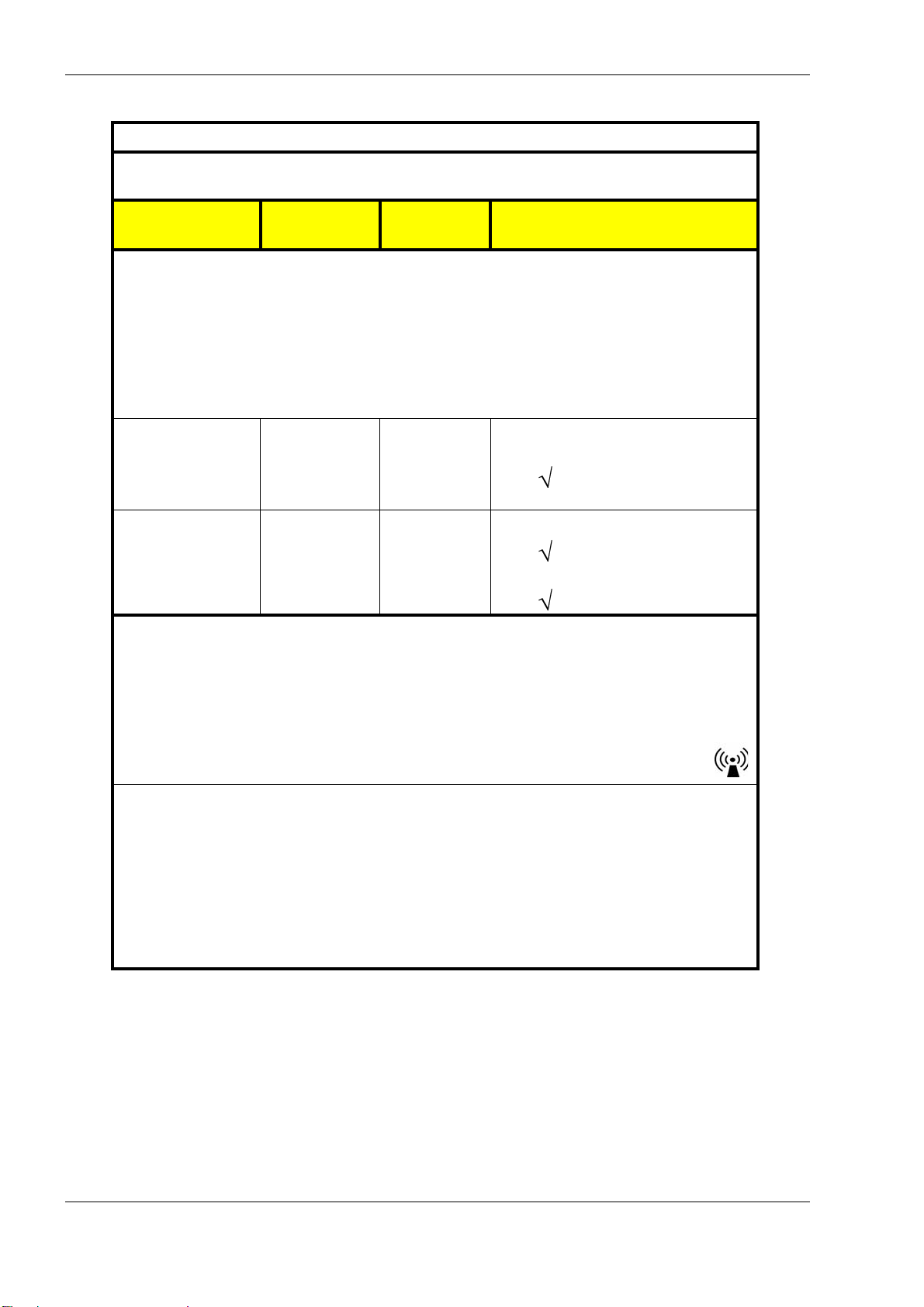
PillCam Platform
Guidance and manufacturer’s declaration - electromagnetic immunity
The DataRecorder 3 is intended for use in the electromagnetic environment specified below. The
customer or the user of the DataRecorder 3 should assure that it is used in such an environment.
Immunity test
IEC 60601 test
level
Compliance
level
Electromagnetic environment -
guidance
Portable and mobile RF communications
equipment should be used no closer to
any part of DataRecorder 3, including
cables, than the recommended separation
distance calculated from the equation
applicable to the frequency of the
transmitter.
Conducted RF,
3V
rms
3V
rms
Recommended separation distance:
IEC 61000-4-6
Radiated RF ,
150 kHz to
80 MHz
3 V/m
150 kHz to
80 MHz
] = 3 V/m
[E
1
d = 1.2 P
Recommended separation distance:
d = 1.2 P 80 MHz to 800 MHz range
IEC 61000-4-3
80 MHz to
2.5 GHz
d = 2.3 P 800 MHz to 2500 MHz range
NOTE 1: At 80 MHz and 800 MHz, the higher frequency range applies.
NOTE 2: These guidelines may not apply in all situations. Electromagne tic propagation is affected by
absorption and reflection from structures, objects and people.
NOTE 3: P is the maximum output power rating of the transmitter in watts (W) according to the
transmitter manufacturer and d is the recommended separation distance in meters (m).
NOTE 4: Field strengths from fixed RF transmitters, as determined by an electromagnetic site survey
should be less than the compliance level in each frequency range
b
.
a
NOTE 5: Interference may occur in the vicinity of equipment marked with the following symbol:
a Field strengths from fixed transmitters, such as base stations for radio (cellular/cordless) telephones
and land mobile radios, amateur radio, AM and FM radio broadcast and TV broadcast cannot be
predicted theoretically with accuracy. To assess the electromagnetic environment due to fixed RF
transmitters, an electromagnetic site survey should be considered. If the measured field strength in
the location in which the DataRecorder 3 is used exceeds the applica ble RF compliance level
above, the DataRecorder 3 should be observed to verify normal operation. If abnormal performance
is observed, additional measures may be necessary, such as re-orienting or relocating the
DataRecorder 3.
b Over the frequency range 150 kHz to 80 MHz, field strengths should be less than 3 V/m.
,
60 Chapter 5
Page 67
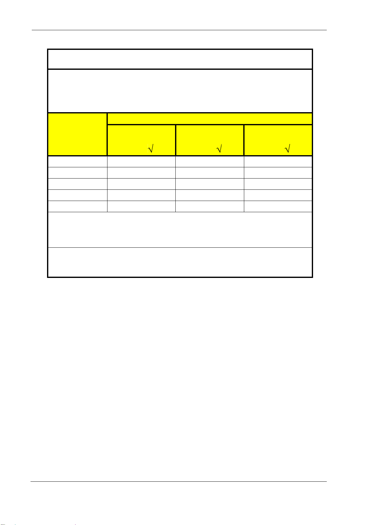
Technical Description
Recommended separation distances between portable and mobile RF
communications equipment and the DataRecorder 3
The DataRecorder 3 is intended for use in an electromagnetic environm ent in which radiated RF
disturbances are controlled. The customer or the user of the DataRecorder 3 can help prevent
electromagnetic interference by maintaining a minimum distance be tween portable and mobile RF
communications equipment (transmitters) and the DataRecorder 3 as recommended below, according to
the maximum output power of the communications equipment.
Separation distance according to frequency of transmitter [m]
Rated maximum
output power of
150 kHz to 80 MHz
80 MHz to 800 MHz
800 MHz to 2,5 GHz
transmitter [W]
d = 1.2 P
d = 1.2 P
d = 2.3 P
0.01 0.12 0.12 0.23
0.1 0.38 0.38 0.73
1 1.2 1.2 2.3
10 3.8 3.8 7.3
100 12 12 23
For transmitters rated at a maximum output power not listed above, the recommended separation distance
d in meters (m) can be determined using the equation applicable to th e frequency of the tran smitter, where
P is the maximum output power rating of the transmitter in watts (W) according to the transmitter
manufacturer.
NOTE 1: At 80 MHz and 800 MHz, the separation distance for the higher frequency range applies.
NOTE 2: These guidelines may not apply in all situations. Electromagnetic propagation is affected by
absorption and reflection from structures, objects and people.
Chapter 5 61
Page 68

PillCam Platform
62 Chapter 5
Page 69
Chapter 6
Note
Caution
!
Warning
Note
Maintenance
Charging DataRecorder
Disclaimer
The DataRecorder cradle is a non-medical device, used for charging the DataRecorder from Given
Imaging Ltd.
Important Safety Instructions
Before using the DataRecorder Cradle, read all instructions on cautionary
markings on the Cradle, on the Battery and on the DataRecorder.
Use only the provided power cable for the DataRecorder Cradle.
Charge the DataRecorder in its dedicated Cradle only.
Changes or modifications to this equipment not expressly approved by the
party responsible for compliance (Given Imaging Ltd.) could void the user’s
authority to operate the equipment.
Use only a fully charged DataRecorder. In general, including first time use, charging the
DataRecorder is an overnight process and should not be performed in the vicinity of the patient.
When you receive the DataRecorder after an examination, charge it immediately until the green
LED is lit, and leave it in its cradle.
This equipment has been tested and found to comply with the limits for a
Class B digital device, pursuant to part 15 of the FCC Rules. These limits are
designed to provide reasonable protection against harmful interference in a
residential installation. This equipment generates, uses and can radiate radio
frequency energy and, if not installed and used in accordance with the
instructions, may cause harmful interference to radio communications.
However, there is no guarantee that interference will not occur in a particular
Given Imaging Ltd. 63
Page 70
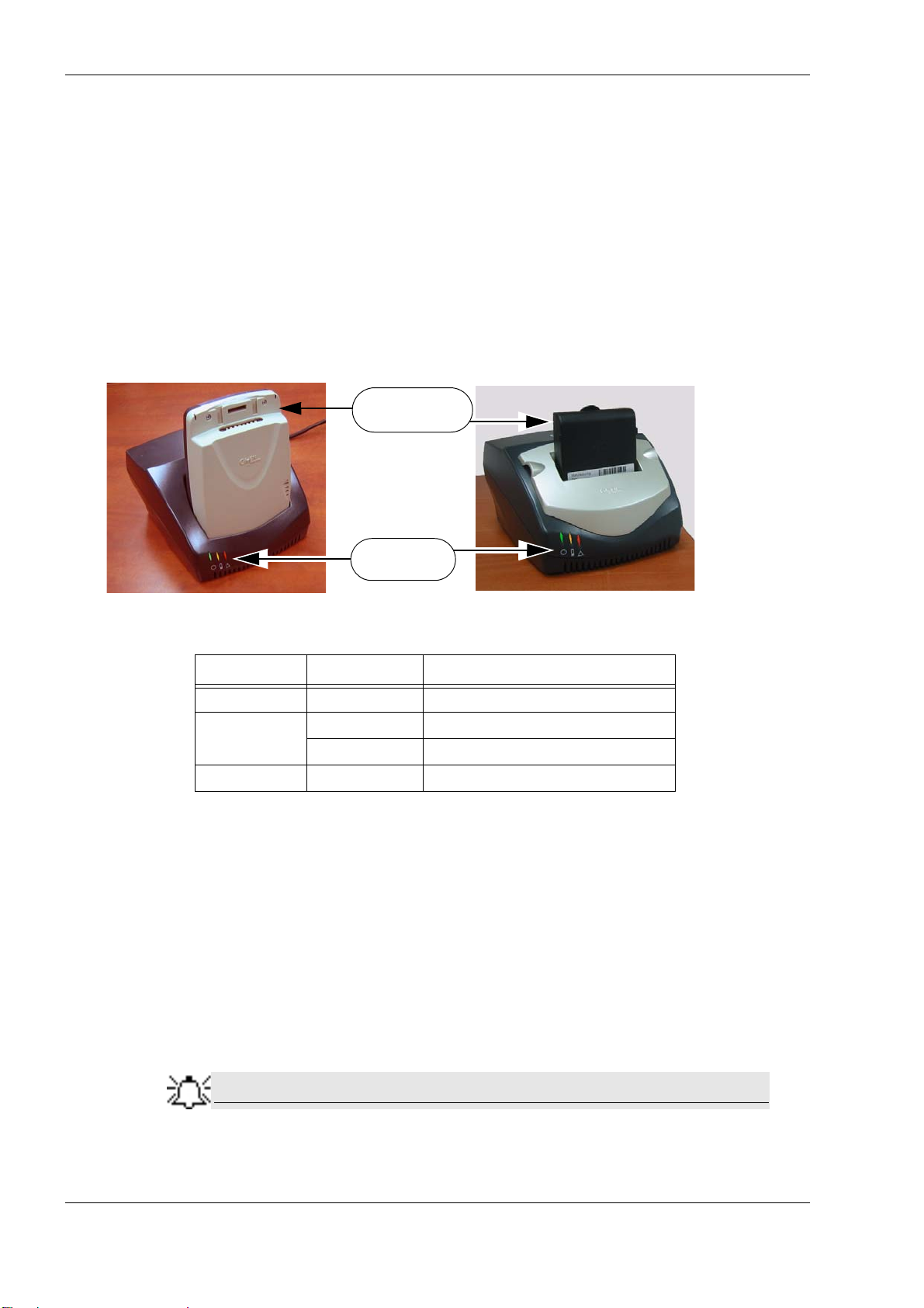
PillCam Platform
Note
DataRecorder 2
with Battery
or Adaptor
Green, Orange
and Red LEDs
DataRecorder 2
installation. If this equipment does cause harmful interference to radio or
television reception, which can be determined by turning the equipment of f and
on, the user is encouraged to try to correct the interference by one or more of
the following measures:
• Reorient or relocate the receiving antenna.
• Increase the separation between the equipment and receiver.
• Connect the equipment into an outlet on a circuit di ff erent from that to which
the receiver is connected.
• Consult the dealer or an experienced radio/TV technician for help.
The following table lists and explains the LEDs (from left to right) of the DataRecorder 2 Cradle and
their meaning:
LED Status Explanation
Green On Battery Pack is ready for use
On Battery Pack is charging
Orange
Blinking Battery Pack is discharging
Red On Battery Pack is faulty
To Charge the DataRecorder 2
1. First plug the power cable into the cradle and plug the power cable into the wall outlet.
All three LEDs turn on for a self-test that takes 5 seconds. After 5 seconds all LEDs turn off, and
the cradle is idle and ready for use.
If after the self-test the red LED blinks, the battery pack is faulty. Contact Given Imaging
Customer Support.
2. Insert the DataRecorder 2 or the DataRecorder 2 Li-Ion battery with its adaptor into the cradle.
All three LEDS of the cradle blink for 4 seconds, before the charging process starts (orange
LED is on).
If the Cradle detects that the battery needs refreshing (i.e., the battery gauge
needs recalibration), it will automatically discharge the battery before
recharging it. The orange LED on the cradle blinks during discharging.
64 Chapter 6
Page 71
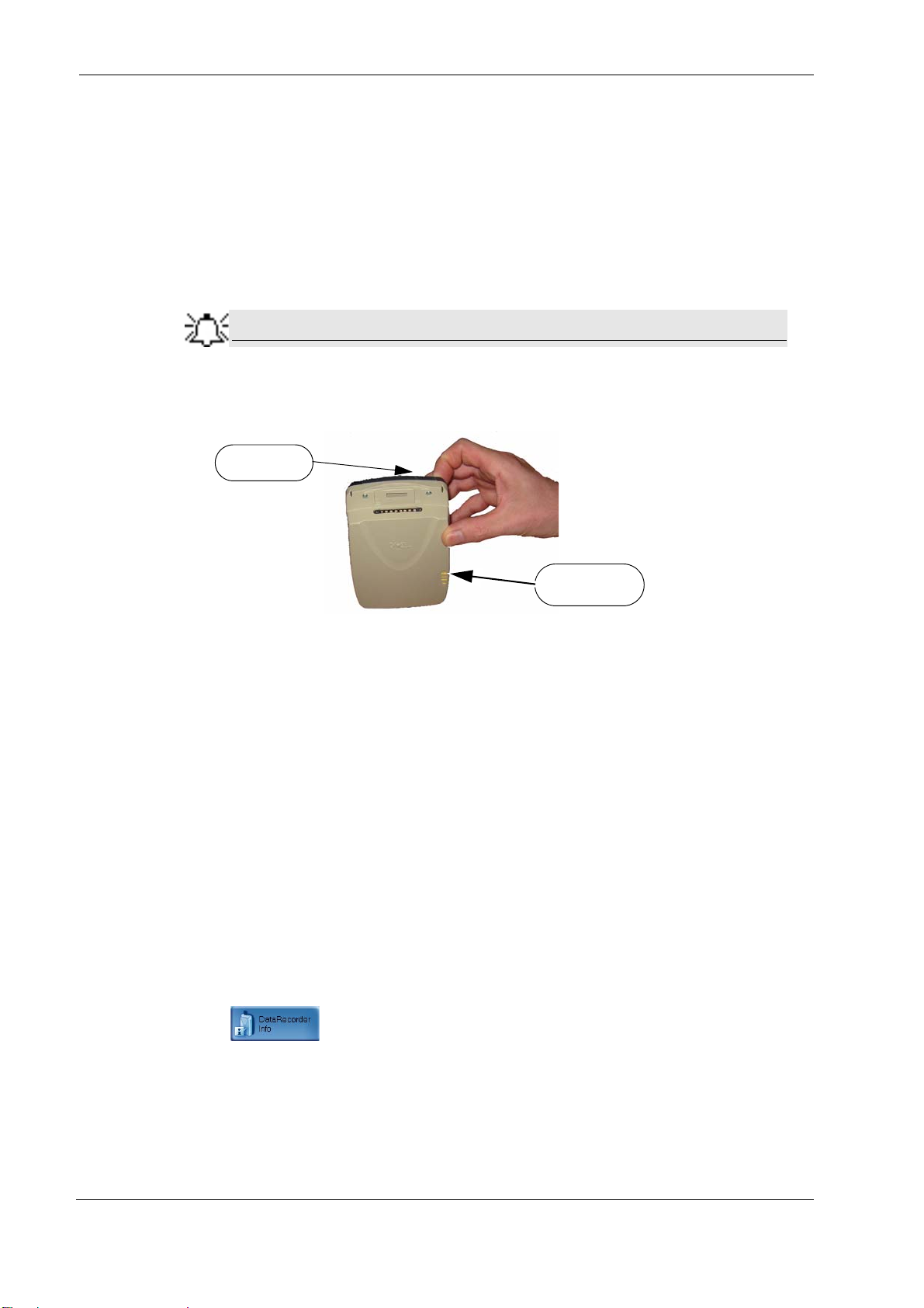
We recommend manually discharging the Dat aRecorder 2 battery once
Note
Push button
LEDs on the
DataRecorder 2
(at the back)
every three months, even if the DataRecorder 2 is not used. This will
prevent the DataRecorder 2 from discharging automatically at an
inconvenient time, since the discharge is an overnight process that may
take up to 12 hours.
As soon as the DataRecorder 2 or its Battery Pack are fully charged, the green LED turns on,
3.
and the Orange LED turns off. Leave the DataRecorder 2 in its Cradle until the next
examination.
You can check the status of the DataRecorder 2 by pushing the button on the
back of the DataRecorder 2 momentarily. All 4 LEDs must be lit before an
examination.
Maintenance
Manual Discharge of DataRecorder 2
If the Cradle detects that the battery needs refreshing (i.e., the battery gauge needs recalibration),
it will automatically discharge the battery before recharging it. The orange LED on the cradle
blinks during discharging.
W e recommend manually discharging the DataRecorder 2 battery once every three months, even
if the DataRecorder 2 is not used. This will prevent the DataRecorder 2 from discharging
automatically at an inconvenient time, since the discharge is an overnight process that may take
up to 12 hours.
To discharge the DataRecorder 2 Battery
1. Make sure the appropriate battery is inside the DataRecorder 2.
2. Insert the DataRecorder 2 into its cradle.
3. From the Procedures screen, select the relevant DataRecorder 2 by clicking the
DataRecorder 2 bar.
The buttons on the right side of the screen become available.
4. Click to open the DataRecorder Info screen.
5. At the bottom of the screen, click Start Discharge.
A message appears:
discharge?
Discharge may take up to 12 hours. Are you sure you want to start
6.
Click OK.
While the battery is being discharged, its battery status indicates
Chapter 6 65
Discharging:
Page 72
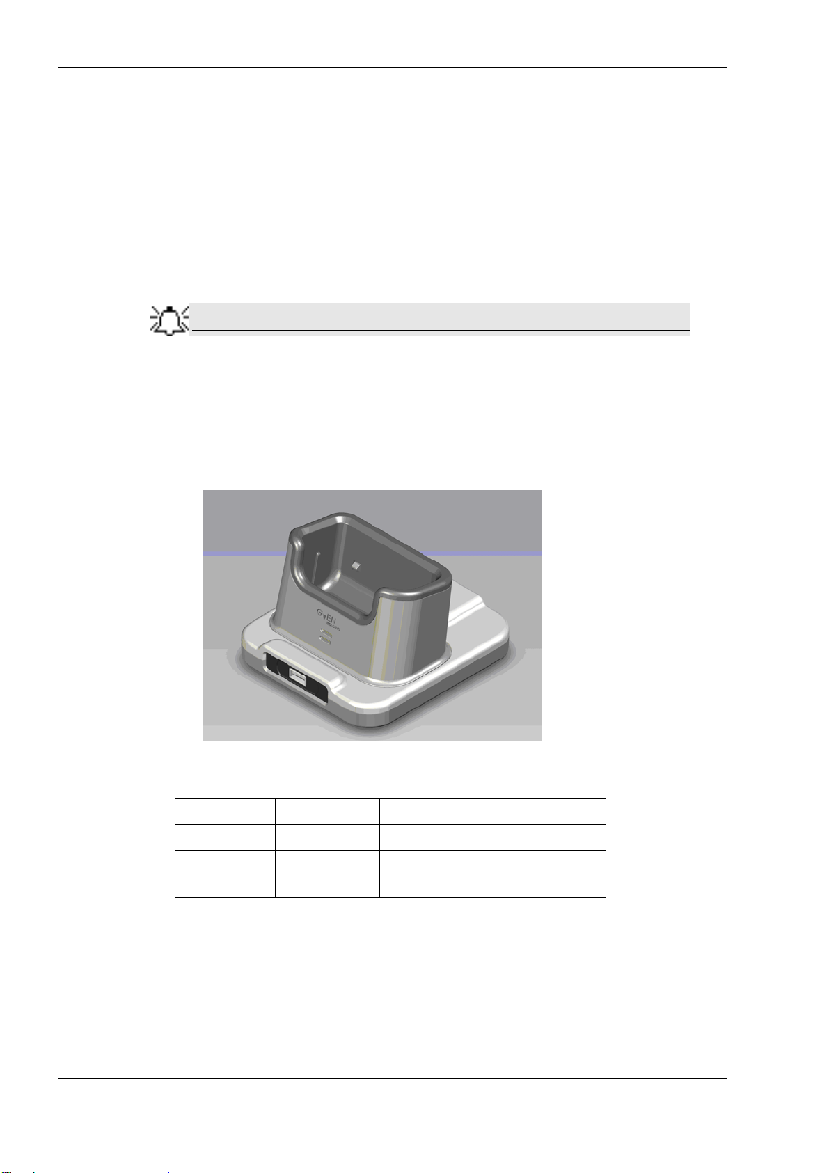
PillCam Platform
Note
• in the bottom left corner of the DataRecorder Info screen
• in the DataRecorder 2 bar in the
• the orange LED on the cradle blinks
7. To return to other RAPID functions, click Close.
8. If you need to stop the discharge (also for automatic discharge) while it is in progress, return
to the
If you stop the automatic discharge process in the middle, the battery LEDs may not indicate
the correct battery status.
For more information on charging the DataRecorder 2, see Charging DataRecorder on page 63.
Make sure the DataRecorder is fully charged for SB and Colon Capsule Endoscopy, and that at
least two of the four battery LEDs light up for an ESO Capsule Endoscopy.
DataRecorders screen
DataRecorder Info screen and click S top Discharge.
Do not charge the battery in the vicinity of the patient.
DataRecorder 3
The following table lists and explains the LEDs of the DataRecorder 3 Cradle and their meaning:
LED Status Explanation
Green On Battery Pack is ready for use
Yellow
On Battery Pack is charging
Blinking Battery Pack is charging
To Charge the DataRecorder
1. First plug the power cable into the cradle and plug the power cable into the wall outlet.
2. Insert the DataRecorder into the cradle. The bottom LED is orange when charging the battery.
3. As soon as the DataRecorder is fully charged, the bottom LED turns green. Leave the
DataRecorder in its cradle until the next examination.
66 Chapter 6
Page 73
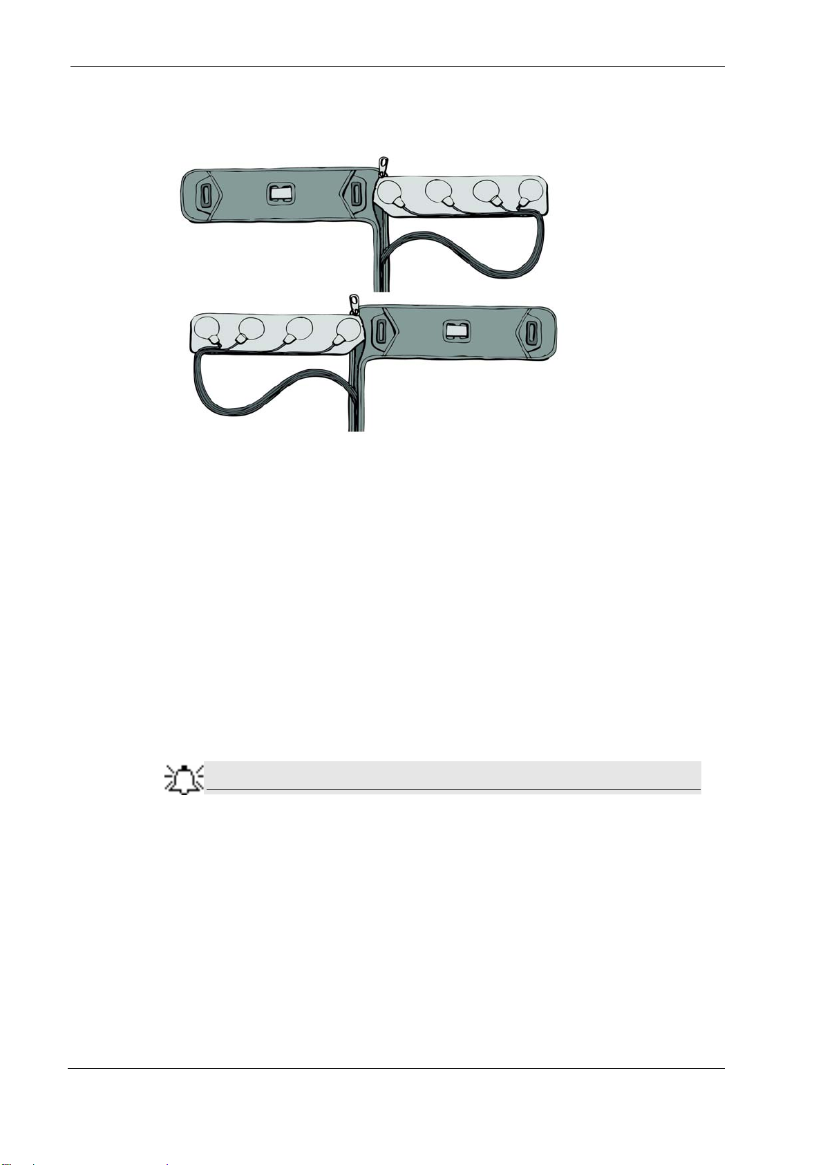
SensorBelt Cleaning
Note
The SensorBelt may be machine washed after removal of the SensorBelt Insert.
Maintenance
Follow instructions on the care label and use a mild detergent.
The surface of the SensorBelt may be wiped with any commonly used disinfectant.
The SensortBelt Insert may be wiped gently with alcohol (up to 70%).
SensorArray Cleaning
For mild cleaning (dirt, sweat), wipe the sensors gently with alcohol (up to 70%). The alcohol
will not remove the adhesive. Since alcohol is a polar solvent, do not use lavishly, and allow to
dry for 20 minutes.
To remove adhesive from the SensorArray (not from the human body), use White Benzene.
White Benzene MUST be used in a ventilated area with all precautions
defined in the manufacturer’s instructions.
Alternatively, use one of the following medical adhesive removers to remove adhesive:
• B-508 Secure Solvent
• B-202 Hollister Solvent
• B-206 Detachol Adhesive Remover
Use all precautions as defined by the manufacturer.
Chapter 6 67
Page 74

PillCam Platform
68 Chapter 6
Page 75

Troubleshooting
RAPID Video
Problem Cause Action
Short Video • Capsule
• DataRecorder Battery
• DataRecorder Mishandling
Gaps • Capsule
• Interference
• Mishandling
• Physiological
Bad image quality • Stripes in video
• Pixilation/confetti
• Dark/red/orange image
Video shorter than
capsule operating time
without either ingestion
phase images or body
exit images
No Localization Malfunc tion of the SensorArray Contact Customer Support
•Capsule
• DataRecorder Battery
• Interference
• Contact Customer
Support
• Send video on
CD/DVD
• Inform Capsule Lot #
• Do not use the same
DataRecorder
• Send video on
CD/DVD
• Contact Customer
Support
Chapter 7
Saving and Opening Video
Problem Cause Action
Cannot locate video • Video was not saved in
E:\Videos
• Incorrect patient’s name
Cannot locate findings • Findings were not saved under
patient’s folder
• Findings were saved with the
wrong name
SensorArray
Problem Cause Action
Connector is damaged
Sensor is torn from its wire
Insulation of the sensor wire is
damaged
• Mishandling
• End of Life
Contact Customer Support
•See Saving Your
Findings in chapter
four of Book 3: Using
the RAPID Software
• Contact Customer
Support
Contact Customer Support
Given Imaging Ltd. 69
Page 76

PillCam Platform
Printer
Problem Cause Action
Cannot print report Printer is turned off Turn printer on
CD/DVD
Problem Cause Action
Cannot burn CD/DVD CD/DVD is not blan k or compatible
Cannot eject CD/DVD A video on the disc is open Close the video and retry
RAPID Software
Printer is not set as default printer Set printer to
Printer
Printer has a malfunction Contact Customer Support
Contact Customer Support
with CD/DVD ROM
Wrong Burning procedure Contact Customer Support
Default
Problem Cause Action
Cannot open RAPID Software or Hardware corruption Contact Customer Support
Cannot open RAPID
Atlas
Capsule
Problem Cause Action
DOA (Dead On Arrival):
LEDs do not light up
when capsule is removed
from its box
Given Workstation
Problem Cause Action
Blue screen Hardware malfunction
Given Workstation does
not boot up
Given Workstation DOA Transportation mishandling Contact Customer Support
Atlas installation is incomplete or
incorrect
XML corruption Contact Customer Support
Capsule failure
Hardware malfunction Contact Customer Support
1 Send capsule to Given Imaging Ltd.
2 Open another capsule
3 If second capsule from 10-pak is
DOA, contact Customer Support
• Reinstall Atlas
• Contact Customer
Support
1 Send RAPID and Given
Workstation log files
2 Contact Customer Support.
70 Chapter 7
Page 77

Note
Problem Cause Action
Given Workstation does
not recognize USB
storage device
Given Workstation does
not recognize printer
USB storage device is not
compatible
Malfunction of the USB
connection on Given
Workstation
USB storage device
malfunction
Malfunction of the USB
connection on Given
Workstation
Printer malfunction Contact Customer Support
Printer driver is missing Contact Customer Support
Cradle
Problem Cause Action
All LEDs are flashing red All LEDs are flashing
red
DataRecorder cannot be
placed in cradle
Hardware malfunction Contact Customer Support
Troubleshooting
Contact Customer Support
1 Change USB port
2 Contact Customer Support
Contact Customer Support
1 Change USB port
2 Contact Customer Support
1 Disconnect cradle for mains power
2 Reconnect cradle to mains power
3 If problem persists, contact
Customer Support
DataRecorder
Problem Cause Action
Cannot initialize
DataRecorder
Cannot create video Error message is displayed Send error message to
Capsule LED does not blink
in blue when capsule is
activated
Computer does not
recognize DataRecorder
Not enough space...
message is displayed
Workstation freezes during
video creation
• No pairing performed, or
pairing was not
successful
1 Check USB and power
connection
2 Contact Customer Support
Customer Support
Delete PRRs from hard drive
Contact Customer Support
1 perform Capsule pairing
2 If problem persists, contact
Customer Support
3 Send malfunctioned
capsules to Given Imaging
Ltd.
For LED behavior see DataRecorder 3 LED Indications on page 9, and Error
messages displayed on the DataRecorder screen, see DataRecorder 3 Error
Message Guide on page 10.
Chapter 7 71
Page 78

PillCam Platform
Low Signal
If a low signal is detected during the examination, the following message appears.
A low signal detected during the examination may be due to:
• Improper use of the SensorArray
• A defective SensorArray
• A DataRecorder malfunction
If this message is displayed, Contact Customer Support.
Click
OK to close the message.
72 Chapter 7
Page 79

Index
A
Acknowledge Button
Automatic Shutdown
DataRecorder
back pannel connectors
Backup Logs. ....................................... 34
Backup, create ...................................... 34
Battery and Capsule Icons ..................... 11
Battery Status ......................................... 8
Capsule
storage space
Troubleshooting ............................. 70
Capsule ID ........................................... 35
CD/DVD
Troubleshooting
CE mark .............................................. 35
connecting the RAPID Booster .............. 18
connecting the RAPID Workstation ....... 20
connectors of back pannel ..................... 19
Cradle ...................................... 6, 12, 18
LED indications ........................ 6, 12
Troubleshooting ............................. 71
Cradle Connections .......................... 6, 13
CSA mark ............................................ 35
.............................. 8
.............................. 4, 8
B
......................... 19
C
.................................. 18
............................. 70
E
Expiration date
Gastrointestinal tract
Given Workstation ............................... 18
connecting ..................................... 18
Controlling access .......................... 15
voltage .......................................... 18
installing RAPID C2
KVM Switch
Lot number
Low Signal .......................................... 72
Main screen
RAPID C2 Installation CD
.................................... 35
G
.............................. 2
I
............................ 23
K
....................................... 17
L
.......................................... 35
M
............. 23
N
D
DataRecorder
DataRecorder 2
Manual Discharge
DataRecorder 2 Kit ................................. 3
DataRecorder 3
Troubleshooting
DataRecorder 3 Kit ................................. 7
DataRecorder 3 LED Indications ............. 9
DataRecorder 3 Memory Card ............... 47
DataRecorder 3 Screen Icons ................. 11
DataRecorder 2 ...................................... 3
DataRecorder 3 ...................................... 7
................................ 11, 18
........................... 65
............................. 71
Navigation Buttons
Navigation Buttons Legends ................. 12
Non-ionizing radiation ......................... 35
................................................... 17
outlet
Password
Password, change ................................. 33
password, new ..................................... 32
PillCam ESO 2 Capsule ........................ 41
PillCam Platform ................................. 17
Pillcam Platform
............................................. 32
before it arrives .............................. 17
required space
................................ 8
O
P
................................ 17
73
Page 80

PillCam SB 2 Capsule .......................... 40
PillCam SB Capsule ............................. 39
Printer
Troubleshooting
RAPID
Troubleshooting
RAPID C2 Installation CD ................... 23
RAPID Video
Troubleshooting
RAPID Workstation
connecting
RecorderPouch .................................... 14
registration .......................................... 28
RoHs ................................................... 35
............................. 70
R
............................. 70
............................. 69
..................................... 20
S
Workstation Manager ........................... 32
SB SensorBelt
SensorArray .................................. 14, 67
Cleaning ........................................ 67
Troubleshooting ............................. 69
SensorBelt
Cleaning
setting the voltage of APID Workstation 18
sketch
Dell Minitower
System Administration ......................... 31
System Log ......................................... 33
Temperature limits
Type BF equipment .............................. 35
User Account, delete
User, add new ...................................... 32
User, define a ....................................... 31
...................................... 14
........................................ 67
.............................. 19
T
............................... 35
U
............................ 32
V
voltage
Given Workstation
Voltage Select Switch .......................... 18
Wide Screen Compatibility
Workstation
Troubleshooting
......................... 18
W
................... 30
............................. 70
74
 Loading...