

Page 1
G-SECURE-0216
GigaSECURE
CLI User’s Guide
Version 8.3.0
Page 2

COPYRIGHT
Copyright © 2012 Gigamon. All Rights Reserved. No part of this publication may be reproduced, transmitted,
transcribed, stored in a retrieval system, or translated into any language in any form or by any means without
Gigamon’s written permission.
TRADEMARK ATTRIBUTIONS
Copyright © 2012 Gigamon. All rights reserved. Gigamon and the Gigamon logo are trademarks of Gigamon in
the United States and/or other countries. Gigamon trademarks can be found at www.gigamon.com/legal-
trademarks. All other trademarks are the trademarks of their respective owners.
DOCUMENT REVISION – 11/15/12
Page 3

Contents
About This Guide . . . . . . . . . . . . . . . . . . . . . . . . . . . . . . . . . . . . . . . . . . . . . . . . . . . . 9
How To Use This Guide .............................................. 9
Other Sources of Information ......................................... 11
GigaSECURE Documentation......................................... 12
GigaSECURE Online Help ...................................... 12
Contacting Technical Support ......................................... 13
Premium Support ............................................. 13
Contacting Sales ................................................... 13
Chapter 1 Introducing the GigaSECURE
Inline Traffic Distribution Node . . . . . . . . . . . . . . . . . . . . . . . . . . . . . . . . . . . . . . . 15
GigaSECURE Inline Traffic Distribution Node Overview..................... 15
GigaSECURE Features and Benefits .............................. 16
Common GigaSECURE Use Cases........................... 16
Standard G Series Features................................. 17
About G-VUE ................................................ 18
Getting Information on G-VUE ................................... 18
New Features in the G-SECURE-0216 v8.3 Release ....................... 19
Getting Familiar with the G-SECURE-0216 Chassis........................ 20
G-SECURE-0216 Specifications ....................................... 22
Physical Dimensions and Weight ................................. 22
Power Requirements .......................................... 22
Environmental Specifications .................................... 23
Chapter 2 G-SECURE-0216 Update Instructions . . . . . . . . . . . . . . . . . . . . . . . . . 25
Update Paths to Version 8.3 .......................................... 25
Before You Begin – Required Items .................................... 26
Backing Up a Configuration File ....................................... 26
Update Procedure .................................................. 27
Installing G-VUE Software............................................ 28
Next Steps? ................................................. 29
Cloning System Configuration from One System to Another ................. 29
Chapter 3 Getting Started: A Roadmap . . . . . . . . . . . . . . . . . . . . . . . . . . . . . . . . 31
First Steps – Getting Connected and Configured .......................... 32
Next Steps........................................................ 32
3
Page 4

Chapter 4 Rack-Mounting the G-SECURE-0216 Chassis . . . . . . . . . . . . . . . . . . 33
Unpacking the G-SECURE-0216 Appliance.............................. 33
Rack-Mounting the G-SECURE-0216 .................................. 34
Rack-Mounting Procedure ...................................... 34
Chapter 5 Basic GigaSECURE Connections and Configuration . . . . . . . . . . . . 37
Connecting Serial Console, Mgmt Port and Power ........................ 37
Connecting -48 V DC Power Supplies .................................. 40
Establishing a Configuration Session with the GigaSECURE Node ........... 41
Local Connections to the Console Port using the Console Cable ........ 41
Remote Connections to the Mgmt Port ............................ 43
Configuring the Mgmt Port’s Network Settings .................. 43
About IPv4/IPv6 for the Mgmt Port ........................... 43
SSH2 vs. Telnet.......................................... 47
Enabling G-VUE Access ....................................... 49
Connecting to the GigaSECURE Node from G-VUE.............. 49
Command Line Basics .............................................. 51
TheCLIPrompt .............................................. 51
Getting Help in the Command Line Interface ........................ 51
Command Line Syntax – Entering Commands ...................... 52
Command Structure ...................................... 52
The Basic Commands .............................................. 53
Completing the Initial GigaSECURE Setup .............................. 54
Initial User Account Configuration (Optional) ........................ 55
Configuring the GigaSECURE Name and Date ...................... 56
Configuring GigaSECURE Time Options ........................... 56
Setting Time Manually ..................................... 57
Using an SNTP Time Server for System Clock Synchronization .... 57
Using Automatic Daylight Savings Time Adjustments ............. 58
Saving Changes .............................................. 59
Chapter 6 Connecting the G-SECURE-0216 to the Network . . . . . . . . . . . . . . . 61
Connecting the GigaSECURE Node to the Production Network .............. 62
Selecting the GigaSECURE Network Mode ........................ 62
Connect with or without Optical Protection Switch .................... 63
Link Status Propagation and the Optical Protection Switch ........ 63
Sample G-SECURE-0216 Network Connections .................... 64
10G Mode with Optical Protection Switch ...................... 65
10G Mode without Optical Protection Switch ................... 66
1G Optical Mode with Optical Protection Switch ................. 67
1G Mode without Optical Protection Switch .................... 68
Connecting Inline Tools to the G-SECURE-0216.......................... 70
Identifying SFP+ and SFP Transceivers ................................ 70
................................................................ 72
Chapter 7 Configuring GigaSECURE
Packet Distribution . . . . . . . . . . . . . . . . . . . . . . . . . . . . . . . . . . . . . . . . . . . . . . . . . . 73
About GigaSECURE Packet Distribution: Profiles and Distribution Rules ....... 73
4
Page 5

Deploying Inline Tools with the GigaSECURE Node .................. 74
Configuring GigaSECURE Traffic Distribution – Procedure .................. 75
Configuring Profiles ................................................. 76
Reviewing the Factory-Configured Profiles .......................... 76
Creating Custom Profiles with config profile ......................... 77
GigaSECURE Profile Logic ................................. 82
Configuring Profiles for TCP Control Bits ....................... 82
IPv4/IPv6 and Profile Criteria ................................ 83
Working with User-Defined Pattern Matches ........................ 83
User-Defined Pattern Match Syntax ............................... 84
User-Defined Pattern Match Rules ................................ 85
User-Defined Pattern Match Examples ............................. 85
Configuring Distribution Rules......................................... 87
Syntax for config distribution ..................................... 88
Planning the Distribution Model .................................. 89
About the Collector – Explicit and Implicit Collector Destinations ......... 90
Collector Example ........................................ 90
Distribution-Rule Priority .................................... 91
About Load-Balanced Groups ............................... 91
Viewing the Active Distribution Model ......................... 92
Profile and Distribution Maximums ................................ 95
Configuring Heartbeat/Failover ........................................ 96
GigaSECURE Failover Methods .................................. 96
Syntax for config failover ........................................ 97
Using Link Status Propagation .................................. 100
Reviewing Link Status Propagation Settings and Status .......... 100
About Heartbeat Packet Usage ................................. 101
Notes on the Heartbeat Feature ............................. 101
Viewing Heartbeat Configuration/Statistics .................... 101
Opening the Physical and Logical Bypasses............................. 103
Toggling the Logical Bypass .................................... 104
Toggling the Physical Bypass ................................... 105
Reviewing Bypass Settings ..................................... 105
Chapter 8 Configuring GigaSECURE
Security Options . . . . . . . . . . . . . . . . . . . . . . . . . . . . . . . . . . . . . . . . . . . . . . . . . . . 107
About GigaSECURE Security ........................................ 108
Configuring Users and Passwords .................................... 109
Examples .................................................. 110
GigaSECURE Password Policies ................................ 110
Changing Passwords ......................................... 111
Configuring External Authentication (AAA) .............................. 112
Authentication Options ........................................ 112
Syntax for the config system aaa Command ....................... 113
Examples .............................................. 115
Using the GigaSECURE Node with an External Authentication Server . . . 116
Specifying TACACS+ Servers in the GigaSECURE Node ......... 117
Specifying RADIUS Servers in the GigaSECURE Node .......... 120
5
Page 6

Configuring Users in External Authentication Servers ................ 123
Differences in Commands for External and Local Users .............. 124
Chapter 9 Using Configuration Files . . . . . . . . . . . . . . . . . . . . . . . . . . . . . . . . . . 125
Configuration Files and G-VUE ................................. 125
What’s Saved In a Configuration File .................................. 126
Saving a Configuration File ......................................... 127
Viewing the Contents of a Configuration File ............................ 128
Uploading Configuration to a Command File ............................ 128
Pasting the Contents of a Command File into the CLI ................ 129
Storing Configuration Files on an SCP/TFTP Server ...................... 129
Uploading a Configuration File to an SCP/TFP Server ............... 130
Files Not Uploading? ......................................... 130
Downloading a Configuration File from an SCP/TFTP Server .......... 131
Applying Configuration Files......................................... 131
Applying a Configuration File from Flash .......................... 131
Setting a Configuration File to Boot Next .......................... 132
Chapter 10 Working with Port Utilization Measures . . . . . . . . . . . . . . . . . . . . 135
Port Utilization Availability by Port Type .......................... 135
Additional Port Utilization Features in G-VUE ...................... 135
Viewing Port Utilization ....................................... 136
Format of show port-utils Output ............................ 136
Examples.............................................. 137
Setting Port Utilization Thresholds ............................... 137
Utilization Alarm/SNMP Trap Generation ..................... 138
Chapter 11 Using SNMP . . . . . . . . . . . . . . . . . . . . . . . . . . . . . . . . . . . . . . . . . . . . 139
Configuring SNMP Traps ........................................... 140
Adding a Destination for SNMP Traps ............................ 141
Example – Adding SNMP Trap Destinations ................... 141
Deleting SNMP Trap Destinations ........................... 142
Enabling GigaSECURE Events for SNMP Traps .................... 143
Example – All Trap Events Enabled ......................... 144
Receiving Traps ............................................. 145
Configuring the GigaSECURE Node’s SNMP Server ..................... 145
Using SNMPv3 .............................................. 147
Available SNMP Statistics for Data Ports ......................... 148
Chapter 12 Configuring Logging . . . . . . . . . . . . . . . . . . . . . . . . . . . . . . . . . . . . . . 149
About Logging ................................................... 149
Configuring Logging–ARoadmap ................................... 149
Specifying Which Events Are Logged ............................ 150
About syslog.log ........................................ 150
Specifying External Syslog Servers .............................. 151
Packet Format for Syslog Output ........................... 152
Configuring the Facility Identifier for GigaSECURE Events ....... 152
Viewing Log Files ............................................ 152
6
Page 7

Uploading Log Files for Troubleshooting................................ 154
Example – Saving a Log File to a Spreadsheet ..................... 154
Appendix A Command Line Reference . . . . . . . . . . . . . . . . . . . . . . . . . . . . . . . 157
Using SCP for File Transfers......................................... 158
Configure the SCP Server, Too! ................................. 158
config commands ................................................. 158
config distribution ............................................ 159
config failover ............................................... 160
config file ................................................... 163
config logical-bypass .......................................... 163
config network-mode .......................................... 164
config network-port-link-propagation .............................. 164
config physical-bypass ........................................ 164
config password command ..................................... 165
config port-alarm command .................................... 165
config port-alias command ..................................... 166
config port-comment .......................................... 166
config port-params commands .................................. 166
Forcelinkup and Enabling/Disabling Ports ..................... 168
config profile ................................................ 169
config rad_server command .................................... 174
config restore command ....................................... 175
config save command ......................................... 175
config snmp_server commands ................................. 176
config snmp_trap commands ................................... 177
config snmpv3usm ........................................... 178
config sntp_server command ................................... 179
config static_ipv6_addr ........................................ 179
config static_ipv6_def_gateway ................................. 180
config syslog_server .......................................... 180
config system commands ...................................... 180
config tac_server command .................................... 185
config uda command .......................................... 187
config user command ......................................... 188
config web_server command ................................... 189
delete commands ................................................. 190
exit command .................................................... 191
help command .................................................... 191
history command .................................................. 191
install commands.................................................. 191
logout command .................................................. 192
ping command .................................................... 193
reboot command .................................................. 194
reset commands .................................................. 194
show commands .................................................. 195
upload command .................................................. 197
Files Not Uploading? .......................................... 197
7
Page 8

Uploading Configuration Commands to a Text File .................. 197
Appendix B CLI Parameter Limits . . . . . . . . . . . . . . . . . . . . . . . . . . . . . . . . . . . . 199
System Parameters ............................................... 199
User Parameters ................................................. 200
Packet Distribution Parameters ...................................... 200
Port Parameters .................................................. 201
SSH2/Telnet Parameters ........................................... 201
Appendix C GigaSECURE Transceiver Information (SFP/SFP+) . . . . . . . . . . . 203
Notes on Values Shown in this Appendix............................... 203
Supported Transceivers by GigaSECURE Model/Port..................... 204
Transceiver Details................................................ 205
Appendix D Console Port Signaling and Cabling . . . . . . . . . . . . . . . . . . . . . . . 207
Appendix E Protective Cover Screw Sizes . . . . . . . . . . . . . . . . . . . . . . . . . . . . . 209
Index . . . . . . . . . . . . . . . . . . . . . . . . . . . . . . . . . . . . . . . . . . . . . . . . . . . . . . . . . . . . . 211
8
Page 9

About This Guide
This guide describes how to install, connect, configure, and operate
®
Gigamon
’s G-SECURE-0216 inline traffic distribution node via the CLI
interface. GigaSECURE nodes maximize the efficiency and availability of
inline security tools. The G-SECURE-0216 is the first model in the
GigaSECURE product line.
G-VUE Information?
The GigaSECURE inline traffic distribution node can also be used with
™
G-VUE
, a web-based interface for the award-winning G Series of traffic
visibility nodes. See the G-VUE Quick Start, G-VUE User’s Guide, and online
help for details on using G-VUE.
How To Use This Guide
This User’s Guide is divided into several main sections. Each section
corresponds to a different stage of GigaSECURE operations, as summarized
below.
Section Chapter
Welcome to the GigaSECURE Inline Traffic Distribution Node
This chapter introduces you to the GigaSECURE system,
orienting you to the product.
Initial Configuration
These chapters describe how to perform the initial system
configuration of the GigaSECURE system.
After working through these chapters, your unit will be up and
running. You will most likely only need to read these chapters
once.
Configuring Packet Distribution
This chapter describes the core features of the GigaSECURE
system – how to configure the distribution of traffic arriving at
inline network ports to up to eight different inline tools.
You will likely return to this chapter frequently as you use the
product.
Chapter 1, Introducing the GigaSECURE Inline Traffic Distribution
Node
Chapter 3, Getting Started: A Roadmap
Chapter 4, Rack-Mounting the G-SECURE-0216 Chassis
Chapter 5, Basic GigaSECURE Connections and Configuration
Chapter 6, Connecting the G-SECURE-0216 to the Network
Chapter 7, Configuring GigaSECURE Packet Distribution
9
Page 10

Section Chapter
Additional Configuration
These chapters describe additional configuration tasks you
will want to learn about after completing your initial
configuration.
You will return to the chapters as you fine-tune GigaSECURE
usage for your environment.
Appendixes
These chapters provide useful reference information. You will
likely return to these chapters as you have specific questions
about GigaSECURE features.
Chapter 8, Configuring GigaSECURE Security Options
Chapter 9, Using Configuration Files
Chapter 10, Working with Port Utilization Measures
Chapter 11, Using SNMP
Chapter 12, Configuring Logging
Appendix A, Command Line Reference
Appendix C, GigaSECURE Transceiver Information (SFP/SFP+)
Appendix D, Console Port Signaling and Cabling
Appendix E, Protective Cover Screw Sizes
10 CLI User’s Guide
Page 11

Other Sources of Information
Gigamon provides other sources of information that can help you get up to speed with
the equipment, including both PDF documentation and online help.
About This Guide 11
Page 12

GigaSECURE Documentation
Gigamon® provides other sources of information that can help you get up to speed with
the equipment, including both online help and PDF documentation. Your GigaSECURE
product includes the following documents to help you learn about the inline traffic
distribution node:
Document Summary
GigaSECURE CLI User’s Guide
(this document)
G-VUE User’s Guide
GigaSECURE Edition
Command Line Summary Summarizes all available CLI commands on a single page.
Release Note Describes new features and known issues in the release.
GigaSECURE Online Help
There are several ways to use online help:
• Whenever you are working with the command-line interface, you can type either ?
or help to see basic description of GigaSECURE commands.
• Command Completion. If you have partially typed a command, you can press Tab
and the CLI will attempt to complete the command for you based on what’s been
entered so far. If it is unable to complete the command, the CLI will simply redraw
the line with the cursor at the end of the line.
• Word Help. When you are typing a command and are not sure how to spell the
word you are working on, type a ? mark immediately following the partially-typed
word (for example, config x?). The CLI will show you a list of all possible words
using the word entered so far.
Describes in detail how to install, connect, configure, and operate
GigaSECURE inline traffic distribution nodes. Provides detailed
information on all CLI commands.
Describes in detail how to use G-VUE – Gigamon’s web-based
interface for system management and configuration of G Series
platforms.
• Command Help. When you are typing a command and have finished a word but
are not sure what the rest of the syntax is, you can type a space after the word and
then a ?. The CLI will list all possible commands using the words you have entered
so far. For example, if you type config system ?, the CLI will return all possible
config system commands.
12 CLI User’s Guide
Page 13

Contacting Technical Support
Contact Gigamon’s Technical Support department with product questions using the
information in Tab le i . The Technical Support department’s hours of operation are from
8:00 AM to 5:00 PM Pacific Time, Monday through Friday, excluding major U.S.
holidays. See http://www.gigamon.com/gigamon---technical-support for additional
information on Technical Support.
Table i: Technical Support Contact Information
Telephone
E-Mail
Premium Support
Email Gigamon at [email protected] for information on purchasing 24x7 Premium
Support for your GigaSECURE inline traffic distribution node. Premium Support entitles
you to round-the-clock phone support with a dedicated Support Engineer every day of
the week.
Contacting Sales
Ta b l e i i shows how to reach the Sales Department at Gigamon.
Table ii: Sales Contact Information
Telephone
Sales
(408) 263-2024
(408) 263-2022
About This Guide 13
Page 14

14 CLI User’s Guide
Page 15

Introducing the GigaSECURE Inline Traffic Distribution Node
This section introduces the GigaSECURE inline traffic distribution node,
describes its features and functions, and provides an orientation to the
physical layout of the chassis. It includes the following major sections:
• GigaSECURE Inline Traffic Distribution Node Overview on page 15
• New Features in the G-SECURE-0216 v8.3 Release on page 19
• Getting Familiar with the G-SECURE-0216 Chassis on page 20
• G-SECURE-0216 Specifications on page 22
Chapter 1
GigaSECURE Inline Traffic Distribution Node Overview
Security tools such as firewalls and intrusion prevention systems are often
connected inline on production networks, with traffic flowing from the network
segment through the tool and then back onto the production network.
Inline deployment of tools introduces some common challenges and risks to
the network:
• Oversubscription – As network speeds increase, legacy tools can
experience difficulty keeping up with the packet volume. A 10G traffic
stream will quickly render a 1G inline device over-subscribed and
potentially obsolete.
• Failover – When production network traffic is flowing through a tool, the
tool must not fail in a way that causes packet loss. Traffic flowing through
the tool must be instantly re-routed over the production network
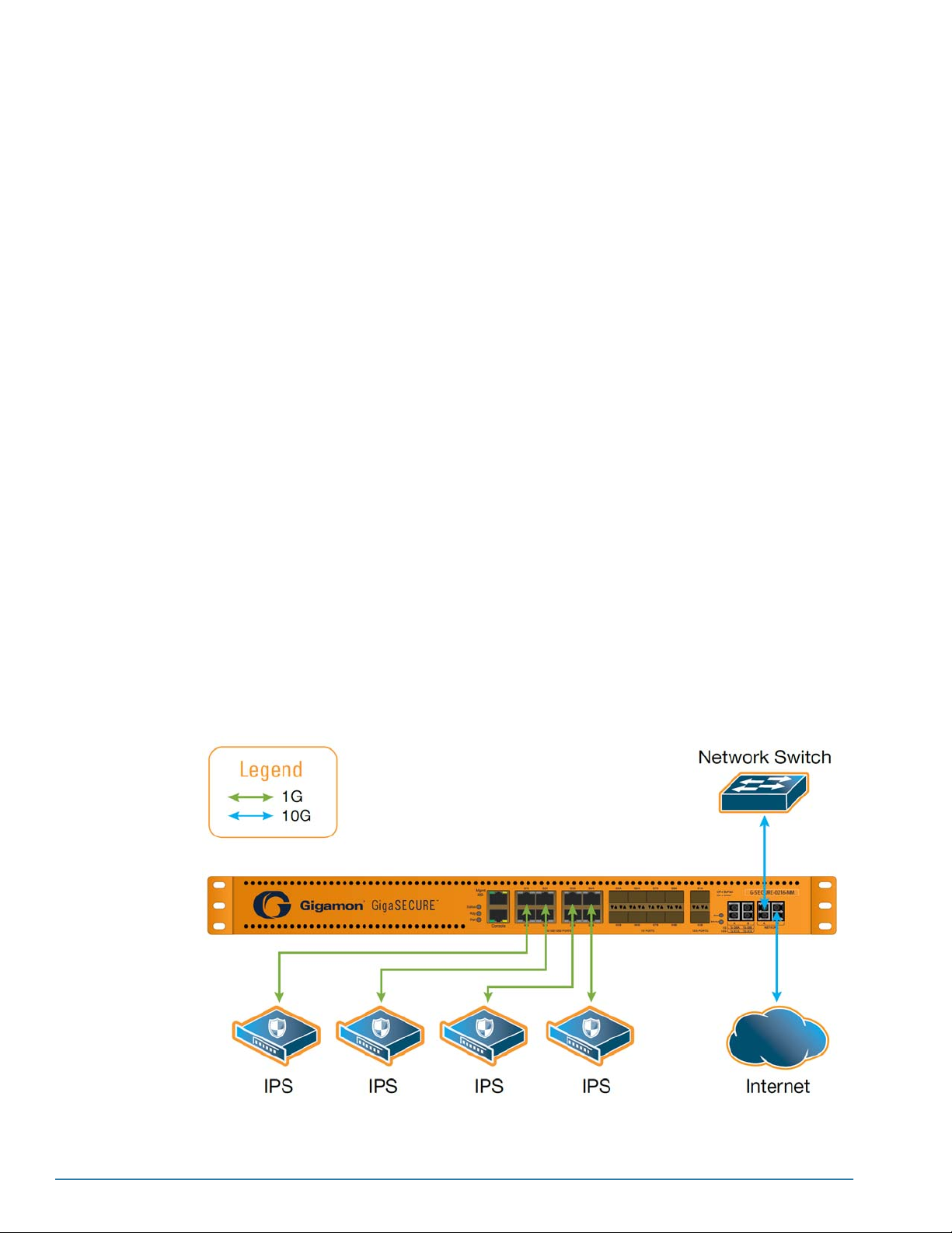
The G-SECURE-0216 inline traffic distribution node addresses both of these
challenges – performance and availability:
• Performance – Traffic enters the G-SECURE-0216 10G ingress port and
is distributed to up to eight 1G inline devices based on user-defined
profiles – sets of packet-matching criteria. You can distribute traffic based
on IP or MAC addresses, as well as by application port number (for
example, 80/HTTP, 443/HTTPS, and so on).
Traffic can be sent to specific tools, load-balanced among groups of tools
based on matching IP flows, or a combination of both. In addition, a
special collector destination makes it easy to send all traffic not matching
any bound profile either back onto the network or to a specified tool.
15
Page 16
• Availability – The G-SECURE-0216 offers both physical and logical bypass
protection for inline tools:
• Physical bypass protection uses an optical switch for instant re-routing of traffic
between the network ingress and egress ports in the event of a power outage,
resulting in zero downtime.
• Logical bypass protection automatically detects link down conditions on
connected tools, either rerouting destination traffic back onto the network or to
other members of a load-balanced group of tools. Customizable heartbeat
packets can be sent to attached inline security tools to monitor for availability.
GigaSECURE Features and Benefits
The G-SECURE-0216 offers the following features and benefits:
• Support for either 10G or 1G network segments.
• Effective use of 1G inline monitoring devices on 10G network segments, protecting
them from oversubscription.
• Session and application-aware traffic distribution to inline tools.
• Single-mode and multimode fiber configurations.
Common GigaSECURE Use Cases
• Deploy multiple inline security appliances on a single link – firewalls, IPSs, NACs,
Web Filters, and so on.
• Monitor 10G data from inline links with 1G security and application monitoring
tools.
• Insert multiple inline Intrusion Protection System (IPS) security devices with low
latency and without link failure.
16 CLI User’s Guide
Page 17

Standard G Series Features
In addition, the G-SECURE-0216 offers many standard features from the G Series of
GigaVUE platforms:
Benefit Descriptions
Intuitive Web Interface The G-SECURE-0216 includes G-VUE, a web-based interface for the G Series of GigaVUE
platforms. G-VUE lets you manage your device from a familiar web browser instead of the CLI,
using intuitive drag-and-drop techniques.
Remote Management Configure the GigaSECURE appliance’s operations from a web-based or command-line
interface:
• Local access over the serial Console port.
• Remote network access using Telnet, SSH2, or HTTPS over the 10/100/1000 Ethernet
Management port.
• Secure access to the CLI/GUI, either through local authentication or optional RADIUS/
TACACS+ support.
Modularized Design Install once and never touch any links again. You can move, add, and reconfigure tools at will
without affecting production networks.
SNMP Support Rely on secure SNMP v3 access to the onboard SNMP agent as well as v1/v2 SNMP traps.
Introducing the GigaSECURE Inline Traffic Distribution Node 17
Page 18

About G-VUE
The GigaSECURE inline traffic distribution node can also be used with G-VUE, a
web-based interface for the award-winning G Series family of traffic visibility nodes.
G-VUE provides you with an intuitive, drag-and-drop interface for your GigaSECURE
inline traffic distribution node. Although the familiar command-line interface will always
be available for all configuration tasks, G-VUE simplifies many common tasks, allowing
you to set up traffic distribution profiles visually instead of entering text in the CLI.
G-VUE can connect to a GigaSECURE node in a supported web browser (see
Connecting to the GigaSECURE Node from G-VUE) on any machine with network
access to the Mgmt port and perform a variety of administrative and operational tasks,
including both day-to-day and system management tasks.
• Configure packet distribution, including:
• Profiles – Sets of user-defined criteria matching specific
packets.
Day-to-Day
Tasks
System
Management
Tasks
• Distribution Rules – Combinations of profiles sending
matching traffic to specified destinations.
• Groups – Load-balanced sets of inline tool destinations.
• View historical Port Utilization (last minute, hour, or week)
• Configure threshold-based Port Utilization alarms
• View per-port statistics.
• Manually configure physical and logical bypass settings.
• Review system settings
• Set port parameters.
• Set up user accounts, user groups, authentication servers, and
security settings.
• Configure an SNTP server for time synchronization.
• Manage configuration files
Getting Information on G-VUE
This guide covers some topics related to G-VUE, especially regarding configuration
tasks for the GigaSECURE appliance’s web server. However, the G-VUE User’s Guide,
and online help are your primary resources for G-VUE documentation.
See Enabling G-VUE Access on page 49 for information on enabling the GigaSECURE
appliance’s web server for G-VUE access.
18 CLI User’s Guide
Page 19

New Features in the G-SECURE-0216 v8.3 Release
Version 8.3 includes the new features summarized in the table below.
Feature
NEW FEATURES in the CLI
SNMP Support for Mgmt Port over IPv6
When using dual IPv4/IPv6 stacks on the Mgmt port, you can now poll either address for SNMP
statistics instead of just the IPv4 address.
Inactivity Timer for Console Port
Version 8.3 includes a new inactivity timer for the serial Console port that lets you time out idle
connections after a specified period of inactivity. The following command lets you toggle the inactivity
timer, as well as specify the amount of time a connection to the Console port can remain idle before it is
automatically disconnected:
config system console_timeout <enable <on|off> | period <10-86400>>
G-VUE Session Protection for Changes to Web Server Settings
Starting with v8.3, the system prevents changes to web server settings when there are active G-VUE
connections. All G-VUE sessions must be closed before the system will let you make changes using
config web_server commands.
NEW FEATURES in G-VUE – See the G-VUE User’s Guide and online help for details.
Rebranded Web Interface
This release changes the name of the Citrus web interface to G-VUE. This change is purely cosmetic
and does not affect the functionality of the interface.
Support for All New CLI Features
All of the new features in the CLI are also supported in G-VUE v3.3.
Introducing the GigaSECURE Inline Traffic Distribution Node 19
Page 20
Getting Familiar with the G-SECURE-0216 Chassis
This section describes the physical layout of the G-SECURE-0216 chassis, including
description of all ports and connectors. The G-SECURE-0216 chassis consists of a 1U,
rack-mountable, 19”-wide chassis with management, network, and tool ports at the
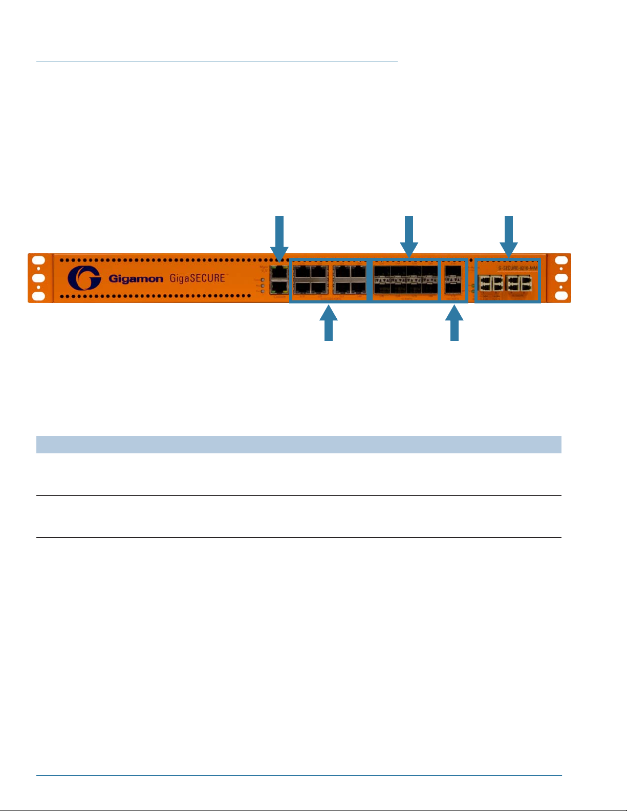
front and power connections at the rear. Figure 1-1 shows the ports at the front of the
G-SECURE-0216 chassis; refer to Table 1-1 for a description of each of the ports.
Optical Protection
Switch (MM or SM)
Mgmt Port
Ports g1..g4
10/100/1000
Copper RJ-45
Ports g5-g8
1G Optical SFP
Ports x1a/x1b
10 Gb Optical SFP+
Figure 1-1: The G-SECURE-0216 Chassis
Table 1-1: G-SECURE-0216 Ports
Port Description
Mgmt Use the Mgmt port for remote configuration of the GigaSECURE node over a 10/100/1000 Ethernet
network, either in the CLI or G-VUE. See Remote Connections to the Mgmt Port on page 43 for
information on establishing a Telnet or SSH configuration session with the GigaSECURE node.
Console Use the Console port for local configuration of the GigaSECURE node over a serial connection. See
Local Connections to the Console Port using the Console Cable on page 41 for information on
establishing a serial configuration session with the GigaSECURE node in a terminal window.
20 CLI User’s Guide
Page 21

Table 1-1: G-SECURE-0216 Ports
Port Description
Inline Tool Port Pairs
1a/1b..g8/gb
Ports x1a/x1b
Inline Network (10G)
The G-SECURE-0216 provides eight pairs of inline tool ports (g1..g8). Each tool pair port has an a
side and a b side (for example, g1a/g1b, g2a/g2b, and so on). By convention, the a side is used for
the external (unprotected) side of the link and the b side is used for the internal (protected) side.
You connect inline tools to a tool pair port so that traffic arriving on the inline network ports flows
through the tool and then back onto the production network.
• Ports g1..g4 provide 10/100/1000 copper RJ-45 connectors.
• Ports g5..g8 use 1G optical SFP transceivers and support 1G speeds only.
NOTE: 850 nm multi-mode or 1310 nm single-mode SFP transceivers are available as standard
options. Zx 1550 nm single-mode SFP transceivers are available as a special order. Refer to
GigaSECURE Transceiver Information (SFP/SFP+) on page 203 for details on supported
transceivers.
Using g1a/g1b or g8a/g8b for the Inline Network Ports in 1G Mode
When operating in 1G mode, either ports g1a/g1b (electrical) or g8a/g8b (optical) become the inline
network ports. You can either cable the ports corresponding to the selected electrical/optical mode
directly to the network segment or take advantage of the optical protection switch and connect jumper
cables between g1a/g1b or g8a/g8b and the corresponding A/B ports on the optical protection switch.
See Selecting the GigaSECURE Network Mode on page 62 for more information.
Use the x1a/x1b inline network ports when operating in 10G mode. You can either connect x1a/x1b
directly to the tapped link or take advantage of physical bypass protection by connecting x1a/x1b to
the A/B monitor ports on the Optical Protection switch using the jumper cables provided with your
product shipment.
The x1a/x1b ports accept 10G SFP+ transceivers:
• 10G SFP+ transceivers are available for optical (SR/LR/ER/LRM) media.
• See Identifying SFP+ and SFP Transceivers on page 70
transceivers you can use with the x1a/x1b ports.
for information on the different 10 Gb
Optical Protection
Switch
The G-SECURE-0216 includes an optical protection switch that operates with the physical bypass
either on or off.
• The unit starts out with the physical bypass on, with the optical protection switch coupling the
fibers between the Network A and B ports. This is the “protected” mode of the unit – during a
physical failover situation, the unit will engage the physical bypass so that traffic flows only
between the Network A/B ports and not to the A/B output ports.
• When you turn the physical bypass off with the config physical-bypass off command, the optical
protection switch decouples the fibers between the Network A/B ports and connects them to the
A/B output ports. This allows traffic to flow on to the GigaSECURE switching fabric via jumper
cable connections from the A/B output ports to the x1a/x1b (10G), g/1a/g1b (1G electrical), or g8a/
g8b (1G optical) input ports.
The optical protection switch accepts standard 850 nm multi-mode or 1310 nm single-mode fiber
cables depending on the model. The silkscreen on the front of the unit indicates the model (MM or
SM).
The Mode LED indicates the status of the physical bypass:
• Off – The physical bypass is on. Traffic is flowing through the Network A/B ports only.
• On – The physical bypass is off. Traffic is flowing to the A/B output ports.
See Connect with or without Optical Protection Switch on page 63 for more information on how to
deploy the G-SECURE-0216 either with or without the use of the optical protection switch.
Introducing the GigaSECURE Inline Traffic Distribution Node 21
Page 22
AC and DC-Powered G-SECURE-0216 Models
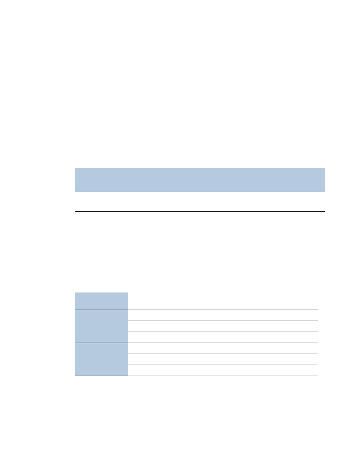
Gigamon provides both AC and DC-powered versions of the G-SECURE-0216 inline
traffic distribution node. See Connecting -48 V DC Power Supplies on page 40 for
information on connecting DC power supplies.
G-SECURE-0216 Specifications
This section provides the physical specifications, power requirements, and
environmental specifications for the G-SECURE-0216 appliance.
Physical Dimensions and Weight
The table below summarizes the dimensions for the G-SECURE-0216 appliance:
Width Height Depth Weight
19.00” (48.26cm) with ears
17.32” (44cm) without ears
Power Requirements
The G-SECURE-0216 appliance is powered by dual redundant, load-sharing,
hot-swappable power supplies. Both AC and DC power supplies are available. The
table below summarizes the electrical characteristics for the G-SECURE-0216
appliance:
OTE: See Connecting -48 V DC Power Supplies on page 40 for instructions on how to
N
connect DC power supplies.
Heat/Power
Dissipation
AC Power
Supplies
(Fully
Populated)
1.74” (1U)
(4.42cm)
For a fully populated system with all ports at 100% traffic load: nominally
100Watts; 340 BTU/hr.
100 to 240V AC
Nominal current requirement: 0.95A @ 110VAC
Frequency: 50/60 Hz
11.81” (30cm) 16 lbs/7.26 kg 25.2 lbs/
(Shipping)
11.43 kg
Weight
DC Power
Supplies
-36 to -72 VDC
Optional external fuse rating: 7A slow-blow
Nominal current requirement: 1.7A @ -48VDC
22 CLI User’s Guide
Page 23

Environmental Specifications
The following table summarizes the environmental specifications for the
G-SECURE-0216 appliance:
Specification Value
Operating Temperature 32ºF to 104ºF
(0ºC to 40ºC)
Operating Relative
Humidity
Recommended Storage
Temperature
Recommended Storage
Relative Humidity
Altitude Up to 15,000ft. (4.6km)
20% to 80%, non-condensing
-4ºF to 158ºF
(-20ºC to 70ºC)
15% to 85%, non-condensing
Introducing the GigaSECURE Inline Traffic Distribution Node 23
Page 24

24 CLI User’s Guide
Page 25
Chapter 2
G-SECURE-0216 Update Instructions
This section describes how to update a G-SECURE-0216 inline traffic
distribution node to the v8.3 release. See the following sections for update
instructions:
• Update Paths to Version 8.3 on page 25
• Before You Begin – Required Items on page 26
• Update Procedure on page 27
• Installing G-VUE Software
• Next Steps? on page 29
Update Paths to Version 8.3
The table below summarizes the upgrade paths to v8.3 for the
G-SECURE-0216 node:
Table 2-1: Upgrade Paths to GigaSECURE v8.3
Starting Release Upgrade Path to v8.3
v8.2.03 v8.2.03 -> v8.3.xx
v8.1.xx v8.1.xx -> v8.2.03 -> v8.3.xx
25
Page 26

Before You Begin – Required Items
Table 2-2 lists the items you will need to update a G-SECURE-0216 node to v8.3.
Obtaining Software Images
You can obtain the image for your system by contacting Technical Support. For each
system you want to update, you will need to provide the output of show diag command
saved as a text file. Use the following information to contact Technical Support:
Table 2-2: Required Items for Update to G-SECURE-0216 v8.3/G-VUE v3.3
Required
Items
TFTP or SCP
Server
Description
You will need to copy (and unzip) the G-SECURE-0216 software packages onto a TFTP or SCP server.
The G-SECURE-0216 node will need the file server’s IP address so that it can connect to the server and
download the image.
NOTE: Gigamon recommends using Linux or UNIX-based SCP servers for best results with the G Series
node. There are freeware SCP/TFTP servers available on the Internet. A web search will provide links to
many implementations.
gveweb83xx.tgz Gzip file containing the G-VUE software. The zip includes both the web installation file and the web-based
software itself. When completely unzipped to your file server’s root directory, you should see the following
files and folders:
• File: gveweb83xx – Web installation file used with install -web command.
• Folder: \web – Files for web-based G-VUE interface.
These common compression tools can work with the G-VUE v3.3 files:
• Linux includes command line tar utility.
• Windows applications supporting the tar format include WinZip and 7-Zip. A web search for tar
windows will provide links to many such utilities.
gve83xx Binary image file containing the updated v8.3 software for the G-SECURE-0216 node.
NOTE: This file may be provided in a zipped format (for example, gve83xx.zip).
Backing Up a Configuration File
Before upgrading the G-SECURE-0216 node, it’s always a good idea to back up a
current configuration file to external storage so you have a backup. You can use the
upload -cfg command to create this backup. The syntax is as follows:
upload -cfg <config file> TFTP-server-ipaddr(A.B.C.D)|SCP-server-ipaddr(scp:[email protected])
26 CLI User’s Guide
Page 27

Update Procedure
Use the following procedures to update a G-SECURE-0216 node to v8.3
Put the Installation Files on your TFTP Server
1. Copy the unzipped installation file (gve83xx) for the G-SECURE-0216 node to your
TFTP/SCP server’s root directory.
Back Up the Configuration File
2. Log in to the system to be updated as a super user.
N
OTE: Normal users do not have the necessary privileges to update the
G-SECURE-0216 software.
3. Use the show file command to see which configuration file has the Next boot file
and Last restored flags set to Ye s. For example:
show file
4. Use the config save command with the nb argument to save your current
configuration to flash memory for version migration. For example:
config save gsecure1.cfg nb
IMPORTANT: The saved configuration file must have the nb flag set to Ye s so that it
loads into memory when the G-SECURE-0216 node is rebooted.
5. Wait for the broadcast message informing you that the config save operation has
completed before continuing to the next step.
Install the G-SECURE-0216 Software
6. Use the install command to install the G-SECURE-0216 software. For example,
the following examples download and install a gve83xx installation file for the
G-SECURE-0216 node from the file server at 192.168.1.10 (TFTP) or 192.168.1.20
(SCP with a user name of gigamon).
TFTP – 192.168.1.10
GigaSECURE>install gve83xx 192.168.1.10
SCP – [email protected]
GigaSECURE>install gve83xx scp:[email protected]
password:*********
7. The system warns you that another image file already exists in the system.
An image named 'gve82xx' already exists in the system - continue (y/n)?
8. Press y to confirm that you want to install the new image.
The system erases the existing image and installs the new one.
I
MPORTANT: Wait for this process to complete. It is important not to power off
or interrupt the system while the software image is being written to flash. The
system prompt will return when the image has installed successfully.
9. When the system prompt reappears, reboot the system with the reboot command.
You are prompted to restart the system with the following message:
System will be re-started and load filename.cfg - continue (y/n)?
G-SECURE-0216 Update Instructions 27
Page 28

10. Press y to restart the system.
11. When the login prompt appears, log in and use the config save command with the
nb option to save your configuration in the new version format and set it to boot
next. For example:
config save gsecure1.cfg nb
Installing G-VUE Software
This section describes how to install the software for G-VUE, the graphical user
interface for G-SECURE-0216 nodes. Keep in mind that G-SECURE-0216 v8.3 must
be installed to use G-VUE v3.3. G-VUE v3.3 will not work with previous
G-SECURE-0216 software versions (and vice-versa).
Installation Procedure
Use the following procedure to install the G-VUE software:
1. Untar/unzip the contents of gveweb83xx.tgz to your SCP/TFTP server’s root
directory. The command in Linux is as follows:
tar -zxvf gveweb83xx.tgz
N
OTE: Some unzip/untar utilities may require you to unzip twice – once for the
top-level gveweb83xx.tgz file and once for the tarball of the \web folder inside.
N
OTE: If you have a previous version of the G-VUE software in your SCP/TFTP
server’s root directory, make sure you choose to overwrite the existing files during
the unzip process.
2. When all files are unzipped/untarred, you should have the following files in your
SCP/TFTP server’s root directory:
• File: gveweb83xx – Web installation file used with install -web command.
• Folder: \web – Files for web-based G-VUE interface.
3. Use the install -web command to install G-VUE. For example:
TFTP – 192.168.1.10
GigaSECURE>install -web gveweb83xx 192.168.1.10
SCP – [email protected]
GigaSECURE>install -web gveweb83xx scp:[email protected]
password:*********
The installer copies the G-VUE software from your SCP/TFTP server to the
G-SECURE-0216 node, returning you to the system prompt when finished.
N
OTE: If you are using SCP and the ser ver requires a password, you will be
prompted for it before the software is downloaded.
I
MPORTANT: Wait for this process to complete. It is important not to power off
or interrupt the system while the software is being written to flash. The
system prompt will return when the installation is complete.
28 CLI User’s Guide
Page 29

Next Steps?
Refer to Enabling G-VUE Access on page 49 for information on enabling the
G-SECURE-0216 node’s web server and connecting with G-VUE.
Cloning System Configuration from One System to Another
This release includes a -clone argument for the install command that lets you
download and apply a command file stored on an SCP/TFTP server to the
G-SECURE-0216 node. With a single command, you can clone one system’s
configuration to another. The overall procedure is as follows:
1. Log in as a super user to the system whose configuration you want to apply to a
second box and use upload -cmd to upload a command file containing its
configuration to an SCP/TFTP server.
For example, the following command uploads the running configuration to a
command file named cloneconfig.txt on the SCP server at 192.168.1.20 with the
username root:
GigaSECURE>upload -cmd -running scp:[email protected] cloneconfig.txt
Creating system commands...
Reading running cfg from memory...
Converting to commands...
Uploading config-text file....
Config file upload to file cloneconfig.txt succeed (12436 bytes).
NOTE: If you don’t specify a filename for the command file, it’s generated
automatically using the chassis type and serial number.
2. Log in to the system to be reconfigured and use the following command to apply
the clone configuration to the second system:
install -clone <command file from Step 1> <SCP/TFTP server address>
In this example, the exact command would be:
install -clone cloneconfig.txt scp:[email protected]
When you apply the clone configuration, the G-SECURE-0216 node downloads the
configuration file to the target system and makes sure the current software version
is compatible with the command file. Then, each line in the file is applied to the
system and printed to the CLI with a -> prefix. Issues and errors are displayed in
blue so you can identify issues that need to be addressed after the clone
procedure.
3. When the system finished the clone procedure, it prompts you to save the new
configuration. Make sure you include the -nb argument if you want to use the new
configuration the next time the system restarts.
4. If any of the settings in the clone configuration file require a restart, the system
prompts you to reboot.
G-SECURE-0216 Update Instructions 29
Page 30

30 CLI User’s Guide
Page 31

Getting Started: A Roadmap
This chapter provides a flow chart of the major steps you need to perform to
get a GigaSECURE inline traffic distribution node up and running on your
network. It also describes what you should do once you have completed the
initial setup of the unit.
• First Steps – Getting Connected and Configured on page 32
• Next Steps on page 32
Chapter 3
31
Page 32
First Steps – Getting Connected and Configured
You’ve received your GigaSECURE inline traffic distribution node and now you’re ready
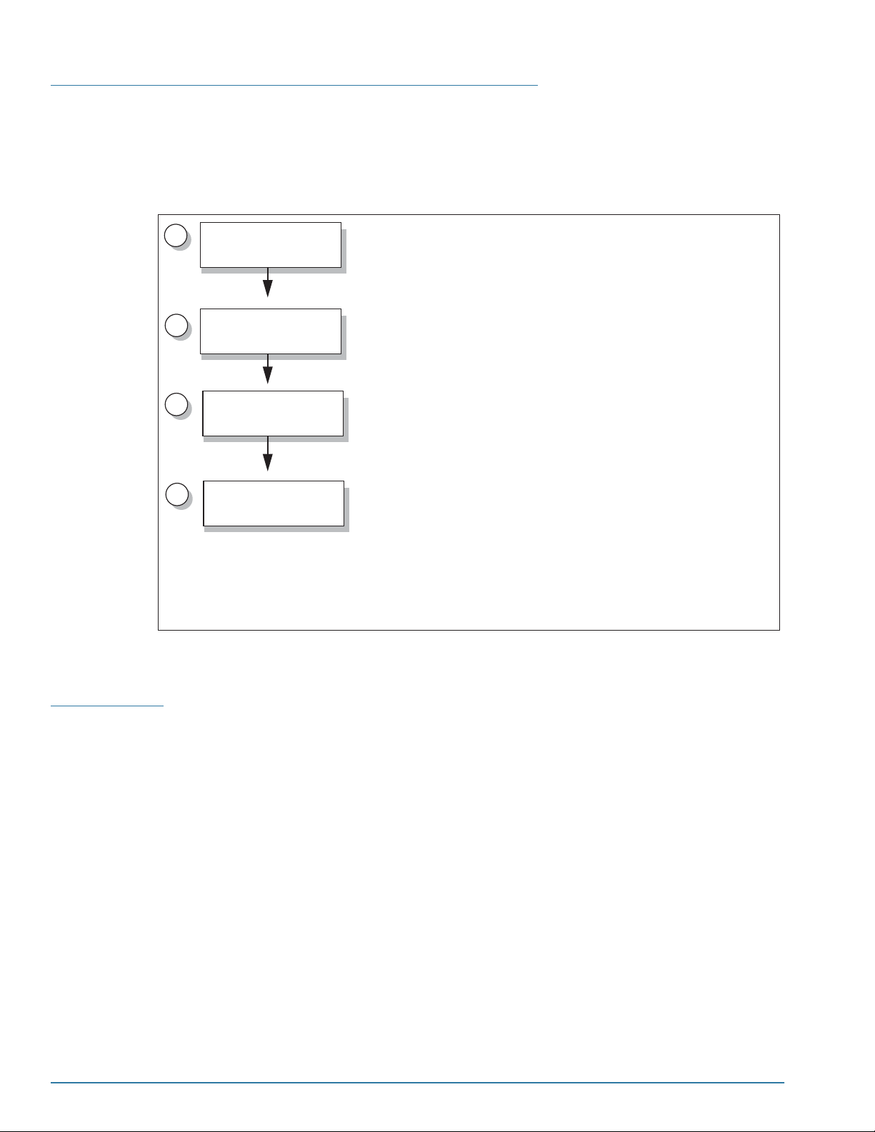
to get up and running. Figure 3-1 shows the major steps you need to perform to get the
GigaSECURE appliance out of the box, into a rack, plugged in, and running on your
network:
1
2
3
4
Rack-Mount
GigaSECURE Chassis
Make GigaSECURE
Connections
Access the Command
Line Interface
Configure Basic
Options
Step 1: Rack-Mount GigaSECURE Chassis
See Rack-Mounting the G-SECURE-0216 Chassis on page 33.
Step 2: Connect GigaSECURE Appliance
See Connecting the G-SECURE-0216 to the Network on page 61.
Step 3: Access the Command-Line Interface
See Basic GigaSECURE Connections and Configuration on
Step 4: Configure Essential Options:
• Get familiar with the CLI
• Configure System Options
• Configure Users and Passwords
• Authorize and enable the GigaSECURE web server for G-VUE
connections
• Set the Name, Date, and Time
See the sections beginning with Command Line Basics on page 51.
Next Steps
Figure 3-1: Getting Started Roadmap
Once you’ve performed the initial configuration of the GigaSECURE unit, installing,
connecting, and configuring the unit, you’re ready set up packet distribution, specifying
how traffic flowing through the GigaSECURE unit’s input ports is distributed through up
to eight inline tools.
See Configuring GigaSECURE Packet Distribution on page 73 for information on these
day-to-day GigaSECURE tasks.
32 CLI User’s Guide
Page 33

Chapter 4
Rack-Mounting the G-SECURE-0216 Chassis
This section describes how to unpack and rack-mount the G-SECURE-0216
chassis. The section covers the following major topics:
• Unpacking the G-SECURE-0216 Appliance on page 33
• Rack-Mounting the G-SECURE-0216 on page 34
Unpacking the G-SECURE-0216 Appliance
Unpack the G-SECURE-0216 appliance and inspect the box it was shipped
in. If the carton was damaged, please file a claim with the carrier who
delivered it.
Remove the protective shipping covers and screws. Save the protective
shipping covers and replace the screws in the holes on the system so that
they are easily saved in case you need to ship the system again.
Next, select a suitable location for the rack unit that will hold the
G-SECURE-0216 appliance. Choose a location that is clean, dust free, and
well ventilated. You will need access to a grounded power outlet. Avoid areas
where heat, electrical wire, and electromagnetic fields are generated.
Plan for enough clearance in front of a rack so you can open the front door
completely (approximately 25 inches) and enough clearance in the back of
the rack to allow sufficient airflow.
33
Page 34

Rack-Mounting the G-SECURE-0216
Safety Precautions
There are a wide variety of racks available on the market. Make sure you consult the
instructions provided by your rack vendor for detailed mounting instructions before
installing the G-SECURE-0216 chassis.
OTE: Before rack-mounting the G-SECURE-0216 chassis, make sure you have read
N
the following safety precautions:
• Make sure you install any stabilizers provided for the rack before installing the
chassis. Unsecured racks can tip over.
• Make sure you install boxes in the rack from the bottom up with the heaviest boxes
at the bottom.
• Make sure you provide adequate ventilation to the systems installed in the rack.
Rack-Mounting Procedure
This section describes how to rack-mount the G-SECURE-0216 in a standard 1U rack
space using the hardware provided with the chassis. The G-SECURE-0216 mounts in
an EIA-standard 19” or 24” telco rack or equipment cabinet, up to 39 inches deep.
G-SECURE-0216 systems are shipped with rack ears for front-mounting or
center-mounting (Figure 4-1) in either a four-post or two-post rack. Change the
direction of the rack ears depending on whether you are front-mounting or
center-mounting.
34 CLI User’s Guide
Page 35
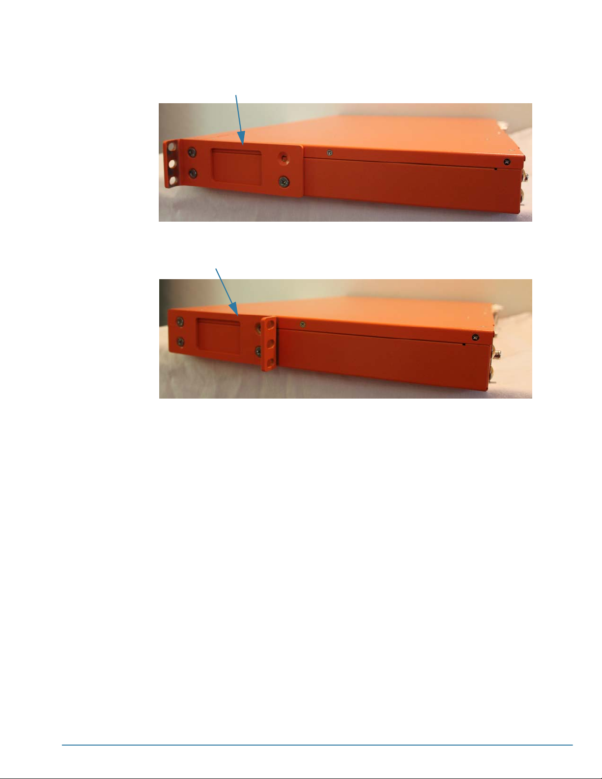
Front-Mounting Rack Ears
In this picture, the rack ears are attached facing towards the front of the chassis.
Center Mounting Rack Ears
In this picture, the rack ears are attached facing towards the rear of the chassis.
Figure 4-1: Attaching Rack Ears for Front/Center-Mounting
To mount the G-SECURE-0216 chassis in a rack:
1. Attach the orange rack ears to the front of the unit using the supplied screws.
As shown in Figure 4-1, you can attach the rack ears facing towards either the front
or the rear of the chassis. Select the orientation that best fits your rack. For
example, one position may provide better clearance for rack doors at the front of the
chassis.
2. While one person supports the weight of the unit with the rack ears flush to the
chassis, a second person can attach the ears to the rack with the supplied screws.
Rack-Mounting the G-SECURE-0216 Chassis 35
Page 36

36 CLI User’s Guide
Page 37

Chapter 5
Basic GigaSECURE Connections and Configuration
This section explains how to make the basic GigaSECURE connections
necessary to get the box powered up and communicating with a connected
client in the command-line interface. It includes the following major sections:
• Connecting Serial Console, Mgmt Port and Power on page 37
• Connecting -48 V DC Power Supplies on page 40
• Establishing a Configuration Session with the GigaSECURE Node on
page 41
• Command Line Basics on page 51
• The Basic Commands on page 53
• Completing the Initial GigaSECURE Setup on page 54
Connecting Serial Console, Mgmt Port and Power
The G-SECURE-0216 appliance is drilled for ground screws
at the rear left corner of the appliance. Connect grounding
wire with spade lugs to the ground screws on the appliance
and earth ground.
To make basic GigaSECURE setup connections (power, serial Console,
and Ethernet Mgmt):
1. Remove all protective shipping covers from the GigaSECURE node.
N
OTE: Save the protective covers and screws in case you need to ship the
unit to another location at some point. You can reinstall the screws after
you’ve removed the covers to keep them handy.
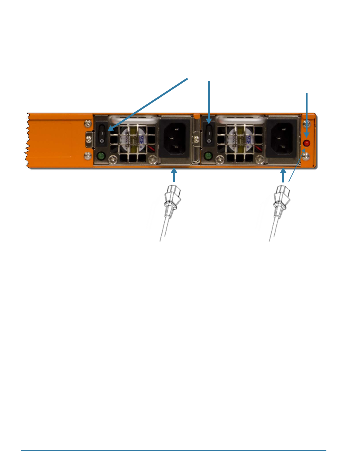
2. Make sure the power supply switches are both in the off position. Then,
plug power cables into each of the GigaSECURE node’s dual power
supplies (Figure 5-1).
NOTE: For information on connecting the optional DC power supplies,
see Connecting -48 V DC Power Supplies on page 40.
3. Plug the other end of the power cables into a power source that can
supply adequate power. For optimal power protection, plug the power
supplies into separate circuits.
37
Page 38
For information on GigaSECURE power requirements, see Power Requirements on
page 22.
4. Turn on the power switches for each of the dual power supplies (Figure 5-1).
Power switches
Power supply alarm
cancel button.
Figure 5-1: Turning on the Power Switches
5. Locate the DB9-to-RJ45 serial cable provided with the GigaSECURE node. This
cable is called a Console cable.
N
OTE:This cable is Cisco-compatible. See Appendix D, Console Port Signaling and
Cabling for pinout details.
6. Connect the RJ45 end of the Console cable to the GigaSECURE node’s Console
port.
38 CLI User’s Guide
Page 39
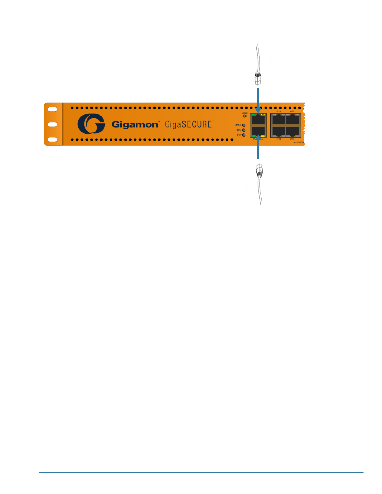
Ethernet cable
DB9-to-RJ45 Console
Cable (RJ45 End)
Figure 5-2: Connecting the GigaSECURE Node’s Console and Mgmt Ports
7. Connect the DB9 end of the Console cable to a PC’s COM port.
8. Connect a standard Ethernet cable (Cat5 or better) to the 10/100/1000 Mgmt port.
9. Connect the other end of the Ethernet cable to an Ethernet network.
10. See Establishing a Configuration Session with the GigaSECURE Node on page 41
for information on how to connect to the GigaSECURE node’s command-line
interface.
Basic GigaSECURE Connections and Configuration 39
Page 40
Connecting -48 V DC Power Supplies
The GigaSECURE node is available with DC power supplies instead of the standard
AC power supplies provided with most systems. This section provides instructions for
connecting a -48 V DC power source to the DC power supplies:
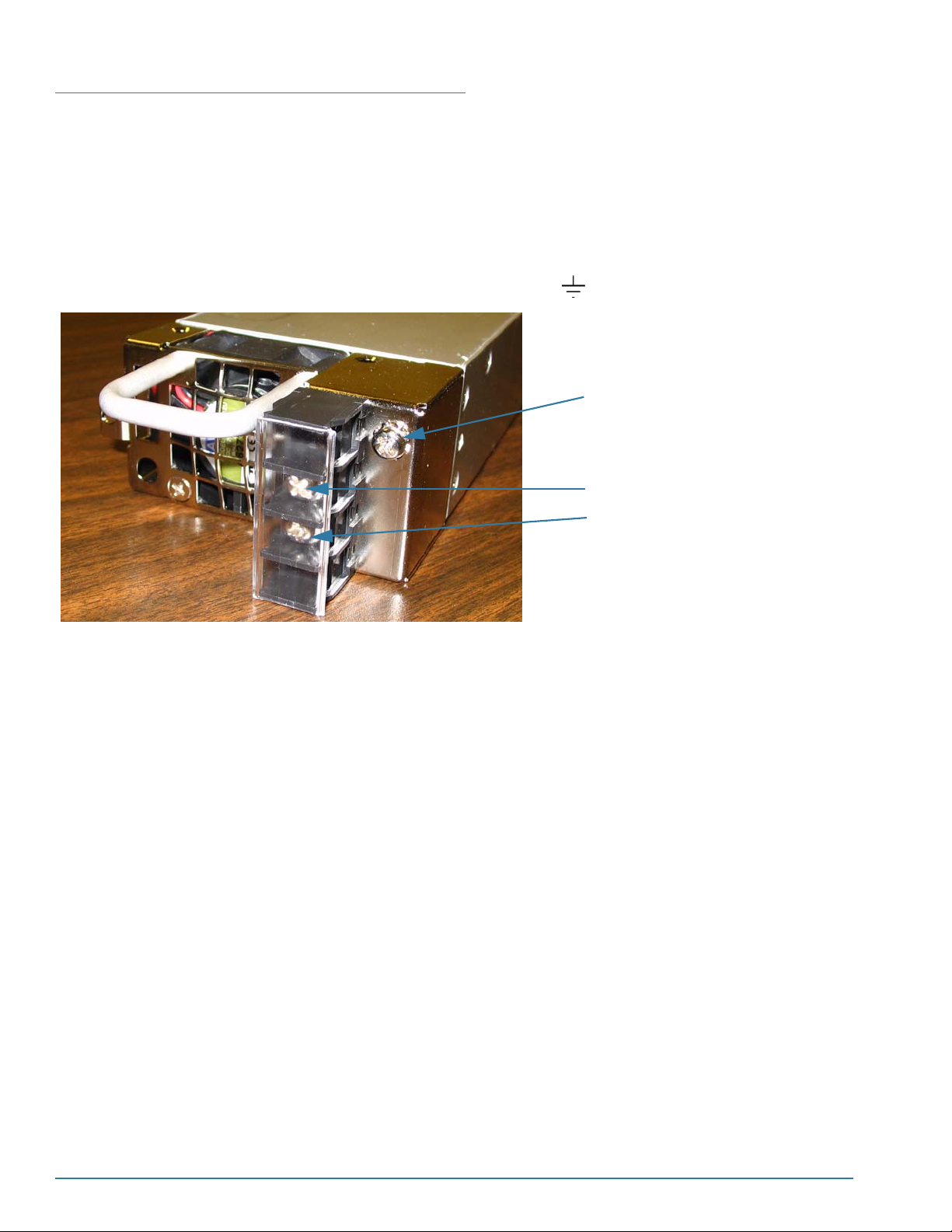
To connect a -48 V DC input to the screw terminal DC power supply:
1. Remove the safety cover from the power terminals.
2. Connect the power supply ground terminal ( ) to earth ground (Figure 5-3).
Ground terminal
0V Return Terminal
-48V Terminal
Figure 5-3: DC Power Supply with Screw Terminals
3. Connect the positive and negative power cables to the screw terminals using a
Phillips screwdriver. See Figure 5-3 for the locations of the terminals:
• The top connector on the DC power supply is the 0V connector.
• The bottom connector on the DC power supply is the -48V return connector.
4. Replace the safety cover over the power terminals.
5. Connect the neutral and negative power cables to the DC power source:
• Connect the neutral wire to the 0V (RTN) connector on the DC power source.
• Connect the negative wire to the -48v connector on the DC power source.
6. Repeat Step 2 through Step 5 for the second DC power supply in the
G-SECURE-0216 chassis.
7. Once you have connected the DC power connections, switch the power buttons for
each of the power supplies to the ON position.
40 CLI User’s Guide
Page 41

Establishing a Configuration Session with the GigaSECURE Node
There are several ways to establish a configuration session with the GigaSECURE
node:
GigaSECURE Interface Instructions
Locally, via a serial
connection to the Console
Command-Line
Interface
G-VUE Interface (Web-based) Enabling G-VUE Access on page 49
port.
Remotely, via a Telnet or
SSH2 connection to the
Mgmt port.
Local Connections to the Console
Port using the Console Cable on
page 41.
Remote Connections to the Mgmt
Por t on page 43
You perform the initial configuration of the GigaSECURE node over the Console port.
Once you have used the Console port to configure the Mgmt port’s network properties,
you can configure the GigaSECURE node remotely using the Mgmt port’s network
connection.
OTE: The same commands are available in the command-line interface regardless of
N
how you connect.
Local Connections to the Console Port using the Console Cable
This section describes how to access the command-line interface using a local terminal
emulation connection to the Console port.
N
OTE: The following procedure explains how to connect to the GigaSECURE system
using the HyperTerminal application provided with MS-Windows. If you use another
terminal emulation application, consult that application’s documentation for information
on establishing a terminal session. The GigaSECURE configuration commands all
work the same once the terminal session is established.
To access the command-line interface over the Console port:
1. Make the basic power and Console cable connections described in Connecting
Serial Console, Mgmt Port and Power on page 37 and power on the GigaSECURE
node.
2. Start HyperTerminal on the PC. Under most circumstances, this program is located
under Start > Programs > Accessories > Communications.
3. Supply a name for the connection in the Connection Description dialog box and
click OK. For example, GigaSECURE Config.
4. Select the COM port connected to the Console cable from the Connect using
dropdown list and click OK. For example, COM1.
5. Configure the port settings for the Console connection as follows (Figure 5-4):
• Bits per second – 115,200
N
OTE: Users with super privileges can change the baud rate for the Console
port.
Basic GigaSECURE Connections and Configuration 41
Page 42
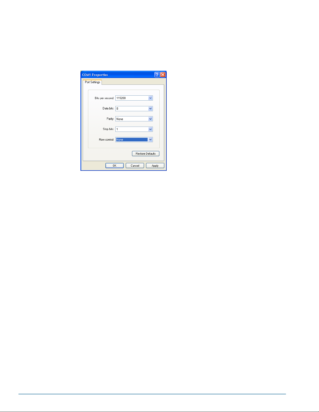
• Data bits –8
• Parity – None
• Stop bits –1
• Flow control – None
Figure 5-4: Setting COM Port Properties for the Console Connection
6. Click OK.
7. The terminal session begins. You may need to press Enter a few times before you
see the login: prompt from the GigaSECURE node.
8. Log in to the command-line interface with the following default user account and
password:
User root
Password root123A!
N
OTE: When you change the default root123A! password, the new password must
conform to the rules described in GigaSECURE Password Policies on page 110.
The system prompt appears, giving you access to the built-in command-line interface.
See Command Line Basics on page 51 for information on getting started with the CLI.
42 CLI User’s Guide
Page 43
Remote Connections to the Mgmt Port
This section describes how to access the command-line interface remotely using either
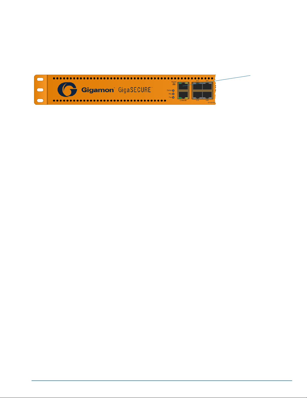
a Telnet or SSH2 connection to the Mgmt port. The Mgmt port is a standard RJ45 10/
100/1000 Ethernet port located at the left front of the chassis (Figure 5-5).
Figure 5-5: G-SECURE-0216 Mgmt Port
NOTE: The Mgmt port supports Auto MDI-X. There is no need to use a crossover
cable.
Configuring the Mgmt Port’s Network Settings
Before you can connect remotely to the Mgmt port, you must configure its IP settings.
Mgmt port for 10/
100/1000 Ethernet
configuration.
You can also configure the Mgmt port’s physical settings. By default, the Mgmt port is
configured to autonegotiate its configuration with the connected equipment. If required
by the connected equipment, you can disable this setting and set specific values for
speed, duplex, and MTU. See Mgmt Port Configuration Procedure on page 45 for the
procedure.
OTE: Per the 802.3 specification, the Mgmt port can only achieve 1 Gb speeds if
N
autonegotiation is enabled. Although autonegotiation is optional for most Ethernet
variants, it is mandatory for Gigabit copper (1000BASE-T).
About IPv4/IPv6 for the Mgmt Port
IPv4 is always active and available on the GigaSECURE node, regardless of whether
IPv6 is also enabled. You can set up the Mgmt port with either a static or dynamic IPv4
address.
OTE: If you configure the Mgmt port to use DHCP, it will obtain a new IPv4 address
N
from a DHCP4 server each time it reboots. After each reboot, you will need to learn this
address in order to connect via SSH2/Telnet
Enabling IPv6
You can enable IPv6 for the GigaSECURE node’s Mgmt port with the following
command, followed by a reboot:
config system ipv6 1
When IPv6 is enabled, the Mgmt port operates with support for both IPv4 and IPv6.
Basic GigaSECURE Connections and Configuration 43
Page 44

Specifying the IPv6 Address Type: Auto-Configured or Static
The Mgmt port can use either auto-configured (the default) or static IPv6 addresses.
You switch between the two types of addresses using the config system
ipv6_autoconfig <1|0> command. The table below summarizes the differences
between the two address types.
OTE: Changing the ipv6_autoconfig setting requires a system reboot.
N
IPv6 Address Type Description
Auto-Configured (Default)
When ipv6_autoconfig is enabled (the default setting when IPv6 is
turned on), the GigaSECURE node obtains an auto-configured,
link-local IPv6 address in one of the following ways:
• IPv6 router advertisements. the GigaSECURE node listens for a valid
IPv6 header and then uses this to construct its IPv6 address.
• Router-solicited IPv6 address. The GigaSECURE node can send out
router solicitation packets and use the responses to generate an IPv6
address.
• Self-generated IPv6 address using an IPv6 header and the Mgmt
port’s MAC address.
NOTE:The Mgmt port does not support DHCP6.
Static
Related Commands and Notes
The GigaSECURE node provides standard delete commands for static IPv6
addresses and default gateways. The table below provides some examples:
When ipv6_autoconfig is disabled (0), you can assign up to five static
IPv6 addresses to the Mgmt port with the config static_ipv6_addr
<ipv6_addr/prefix_length> command. For example:
config static_ipv6_addr 3ffe:308:18:8:21d:acff:fe01:24/64
Note the following when supplying IPv6 addresses:
• Supply the 128-bit IPv6 address in hex as eight, 16-bit fields
separated by colons. Standard conventions for IPv6 address entry
are allowed – you can leave out leading zeroes in a 16-bit block and a
single empty 16-bit block can be represented by a double-colon (::).
• Prefix lengths can be either 32, 64, 96, or 128 bytes.
Configuring a Static IPv6 Gateway
When using static IPv6 addresses, you must also configure a static IPv6
default gateway with the config static_ipv6_def_gateway
<ipv6_addr> command. For example:
config static_ipv6_def_gateway fe80:1::21e:90ff:fe31:8ae6
NOTE: Only a single default IPv6 gateway can be configured. No prefix
is required when configuring the gateway. If the system cannot reach the
specified gateway, the system will reject the setting.
Command Description
delete static_ipv6_addr <all | ipv6_addr> Use this command to delete static IPv6 entries.
delete static_ipv6_def_gateway Use this command to delete a static IPv6 default
gateway.
Keep in mind the following additional notes when using IPv6:
44 CLI User’s Guide
Page 45
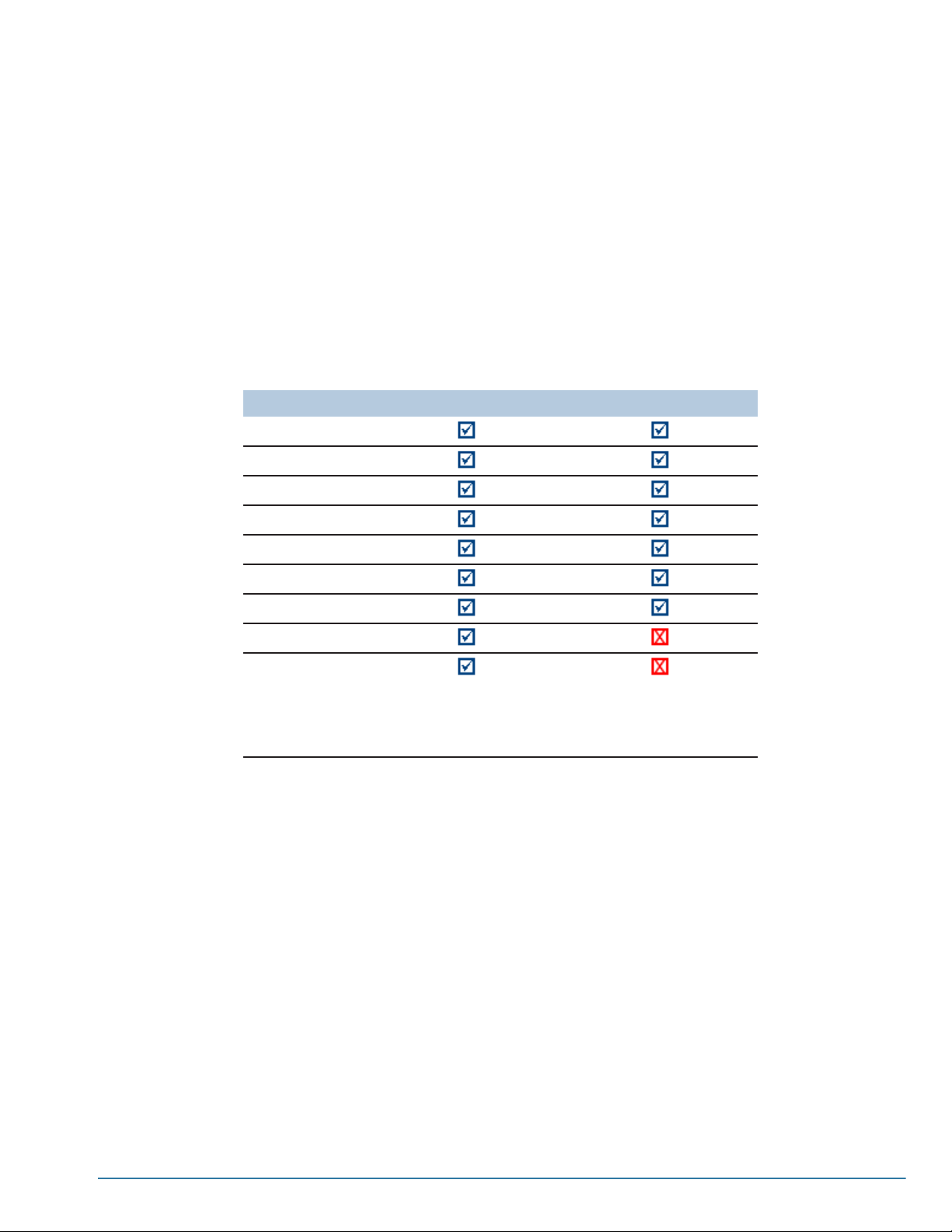
• The show system output includes all IPv6 addresses and the static IPv6 default
gateway, if configured.
• Both enabling IPv6 and switching between the Auto-Configure and Static modes
require system reboots.
• IPv6 addresses are supported in both standalone and cross-box configurations in
both Master/Slave and Classic mode.
Supported Applications for IPv4 and IPv6
The table below summarizes which applications the GigaSECURE node supports over
IPv4 and IPv6. Note that IPv6 support is only provided for listed applications when IPv6
is actually turned on in the CLI (config system ipv6 1).
Application Supported over IPv4? Supported over IPv6?
SSH2
Telnet
TACACS+
RADIUS
SCP
TFTP
SNTP/NTP
SNMP
DHCP
Mgmt Port Configuration Procedure
Use the following procedure to configure the Mgmt port’s network settings:
To configure the Mgmt port’s settings:
1. Connect locally to the GigaSECURE command-line interface over the Console
port using the instructions in Local Connections to the Console Port using the
Console Cable on page 41 and log in as a super user (by default, root with the
password root123).
2. Use the config system mgmt_port command to configure autonegotiation, speed,
duplex, and MTU settings for the Mgmt port.
NOTE:You can still use
DHCP4 for the unit’s IPv4
address when IPv6 is
enabled.
In most cases, the defaults for these settings will work just fine. However,
depending on the type of port to which you are connecting the Mgmt port, you may
need to adjust these settings. For example, if the switch port has autonegotiation
turned off and a mandatory speed of 100 Mbps Full Duplex, the same settings must
Basic GigaSECURE Connections and Configuration 45
Page 46

be made in the GigaSECURE CLI (config system mgmt_port autoneg 0 speed
100 duplex full in this example):
• Autonegotiation – By default, autonegotiation is enabled. You can disable/
enable it with the following command:
config system mgmt_port autoneg <1 | 0>]
NOTE: Per the 802.3 specification, autonegotiation is mandatory for 1 Gb
speeds over copper (1000BASE-T).
• Speed – By default, speed is set to whatever the autonegotiation process
negotiates. After disabling autonegotiation, you can change speeds manually
with the following command:
config system mgmt_port speed <100 | 10>
• Duplex – By default, duplex is set to whatever the autonegotiation process
negotiates. After disabling autonegotiation, you can change duplex settings with
the following command:
config system mgmt_port duplex <half | full>
• MTU – By default, this is set to 1518 bytes, the largest standard Ethernet packet
size. However, you can configure the size to between 320~1518 bytes using the
following command:
config system mgmt_port mtu <320~1518>] (bytes)
NOTE: The GigaSECURE node’s Mgmt port supports RFC 1191 Path MTU
Discovery and can automatically adjust MTU downwards if it discovers that the
specified MTU is too large.
3. Use the config system command’s dhcp, ipaddr, subnetmask, and gateway
arguments to set up the IPv4 network properties for the Mgmt port. Use the
following syntax:
config system [dhcp <1 | 0> ipaddr <addr> subnetmask <xxx.xxx.xxx.xx>]
config system gateway <xxx.xxx.xxx.xx>]
Where:
• dhcp specifies whether the GigaSECURE node will obtain an IPv4 address for
its Mgmt port from a DHCP4 server (1) or use a static address (0). If you set
dhcp to 1, do not supply values for ipaddr, subnetmask,orgateway.
NOTE: If you enable DHCP, you can also use the config system dhcp_timeout
<4 | 10 | 30 | 60 | 100> command to specify the number of seconds the
GigaSECURE node will wait for a response from a DHCP server after querying
for an address.
• ipaddr specifies the static IPv4 address to use.
• subnetmask specifies the subnet mask to be used for the IPv4 address.
• gateway specifies the default gateway to which the Mgmt port should direct its
traffic.
For example, to configure a static IP address of 192.168.1.20 with a standard Class
C subnet mask (255.255.255.0) and a default gateway of 192.168.1.1, you would
type the following command followed by <Enter>.
config system dhcp 0 ipaddr 192.168.1.20 subnetmask 255.255.255.0 gateway 192.168.1.1
NOTE: These commands could also be issued separately as follows:
config system dhcp 0 ipaddr 192.168.1.20 subnetmask 255.255.256.0
46 CLI User’s Guide
Page 47

config system gateway 192.168.1.1
4. By default, only IPv4 is enabled on the GigaSECURE node. You can also enable
IPv6 with the following command, followed by a reboot:
config system ipv6 1
Enabling IPv6 lets you use IPv6 addresses for SSH2, Telnet, TACACS+, RADIUS,
SNTP/NTP, SCP, and TFTP. See Enabling IPv6 on page 43 for more information.
SSH2 vs. Telnet
You can use either Telnet or SSH2 for remote connections to the GigaSECURE node’s
Mgmt port, but not both. The two are mutually exclusive – when one is enabled, the
other is disabled.
By default, Telnet is enabled and SSH2 is disabled. You use the config system ssh2
<1 | 0> command to specify which remote protocol you would like to use. For example,
to enable SSH2, you would use the following command:
config system ssh2 1
Once SSH2 is enabled, Telnet connections are no longer accepted (and vice-versa –
SSH2 connections are not available when Telnet is enabled).
Advantages of SSH2
SSH2 is a more secure choice for remote connections than Telnet, providing an
encrypted channel instead of relying on clear text. It also provides stronger user
authentication capabilities, including the use of a public host key. Host keys uniquely
identify a server, helping guarantee that the server you’re connecting to is the server
you think it is.
The GigaSECURE node includes default RSA and DSA-encrypted public host keys
(SSH2 supports both RSA and DSS encryption algorithms). The first time you connect
to the GigaSECURE node with an SSH2 client, the client will war n you that the host
keys are not in your local cache and show you the actual host key presented by the
GigaSECURE node. Your client will most likely give you the option of trusting the key,
adding it to your local cache. Once you’ve trusted the key, your client will alert you
during connection if a different key is presented.
Verifying the GigaSECURE Appliance’s Host Key During Connection
To verify that the host key presented during an SSH2 connection is in fact the
GigaSECURE node’s, you can connect over the Console port (see Local Connections
to the Console Port using the Console Cable on page 41) and use the show hostkeys
command to see the GigaSECURE appliance’s current public host keys and
fingerprints. Write these down and keep them nearby when you connect via SSH2 the
first time. This way, you’ll be able to compare the actual host key to what your SSH2
client says is being presented. Once you’ve verified that they are the same, you can
choose to trust the host key, allowing future connections to take place seamlessly.
Basic GigaSECURE Connections and Configuration 47
Page 48

Changing Public Host Keys
You can use the config system hostkey command to change the default host keys
provided with the GigaSECURE node. The command has the following syntax:
config system hostkey <dss | rsa> [<768~2048> (bits)]
Acceptable bit values for the host keys are multiples of 8 between 768 - 2048 (for
example, 768, 776, 784, and so on). If you do not specify a key length, GigaSECURE
defaults to 1024 bits.
For example, to configure a new RSA-encryption hostkey, you could use the following
command:
config system hostkey rsa 768
Connecting to the GigaSECURE Node Using SSH2
When SSH2 is enabled, you can use any compliant SSH2 client to connect to the
command-line interface remotely. For example, to connect using the popular SSH2
client, PuTTY:
1. Start PuTTY and enter the GigaSECURE node’s IP address in the Host Name field.
2. Click the SSH protocol radio button.
3. Click Open to open a connection.
4. If this is your first connection PuTTY warns you that the host key presented by the
GigaSECURE node is not in your cache. You can add the key, connect without
adding the key, or cancel the connection. See Verifying the GigaSECURE
Appliance’s Host Key During Connection on page 47 for information on how to
verify that the host key shown is the correct one.
5. Type root in the User name field followed by the root password (root123 is the
default).
Connecting to the GigaSECURE Node Using Telnet
When Telnet is enabled, you can use any compliant Telnet client to connect to the
command-line interface remotely. For example, to connect using the Telnet client
provided with Microsoft Windows:
1. Open a command prompt window and type Telnet.
2. Type open <Mgmt Port IP Address>.
3. Log in with acceptable GigaSECURE credentials (by default, user root with the
password root123A!).
48 CLI User’s Guide
Page 49

Enabling G-VUE Access
G-VUE is Gigamon’s web-based management interface for the G Series family of
GigaSECURE and GigaVUE platforms. You can use G-VUE for many system
configuration, management, and operations tasks. To use G-VUE with a standalone
GigaSECURE node, you must enable its web server, as described below.
Once the web server is enabled, you can use G-VUE for GigaSECURE connections,
as described in Connecting to the GigaSECURE Node from G-VUE on page 49.See
config web_server command on page 189 for information on other web server settings
you can configure.
1. Enter the following command:
config web_server admin 1
2. Check the status of the web server using the show web_server command. Make
sure that both Admin and Operation read 1, indicating that the web server is
enabled and operating correctly. For example:
GigaSECURE>show web_server
Admin : 1
Operation : 1
HTTP port : 80
HTTPS port : 443
Timeout : 20 (minutes)
Connecting to the GigaSECURE Node from G-VUE
After you enable the GigaSECURE node’s web server, it automatically listens for
connections from G-VUE using either HTTP on port 80 or HTTPS on port 443. Use the
following procedure to connect to a GigaSECURE node using G-VUE.
OTE: The GigaSECURE node redirects all incoming HTTP connections to the HTTPS
N
port, unless the HTTPS port has been changed using the config web_server
command. See the G-VUE User’s Guide for details.
1. Open a supported browser. Note that other browsers, such as Chrome™ or
Opera™, are not supported.
Browser Version and Notes
Mozilla Firefox
Windows
Apple
®
Internet Explorer
®
Safari
™
®
®
• Version 3.5+, 4.x, and 5.x
• Version 7.0.x
NOTE: Some display issues
occur with Version 7.0.5730.11.
Use version 7.0.5730.13 instead.
• Version 8.0.x
• Version 9.0.x
• Version 5.0+
NOTE: iPad/Mobile version not
supported.
2. Enter one of the following URLs:
https://<GigaSECURE IP Address>
http://<GigaSECURE IP Address>
Basic GigaSECURE Connections and Configuration 49
Page 50

3. The first time you connect to G-VUE, your browser will prompt you regarding an
invalid security certificate. Depending on the browser you are using, you can avoid
these warnings either by installing a certificate or adding an exception. The table
below has the details:
Browser Add Exception? Install Certificate?
Mozilla Firefox YY
Windows Internet Explorer NY
OTE: Gigamon provides the GigaSECURE node with self-signed certificates for
N
use with G-VUE; you can also create and install a third-party certificate on these
systems. See Using Certificates in the G-VUE User’s Guide for certificate
installation instructions.
Add an exception in Firefox as follows:
a. Click the Or you can add an exception link.
b. Click the Add Exception button.
c. Click the Get Certificate button.
d. Click the Confirm Security Exception button.
The G-VUE login page appears.
4. Enter a valid user name and password and click Login. The default root user
account and password are as follows:
User root
Password root123A!
Configuring Internet Explorer for Use with G-VUE
G-VUE works best in Internet Explorer when the browser is configured to check for
newer versions of stored pages every time pages are visited. Enable this option as
follows:
1. Open Internet Explorer.
2. Select the Tools > Internet Options command.
3. In the General tab, locate the Browsing history section and click its Settings
button.
4. Set the Check for newer version of stored pages: option to Every time I visit
the webpage.
5. Click OK on the Temporary Internet Files and History Settings dialog.
6. Click OK on the Internet Options dialog.
Next Steps?
See the G-VUE online help for details on setting up connections, filters, maps, and so
on.
50 CLI User’s Guide
Page 51

Command Line Basics
This section provides a quick orientation to the GigaSECURE command-line interface
– how to get help, how to enter commands, and so on.
The CLI Prompt
By default, the GigaSECURE command-line interface appears with the GigaSECURE>
prompt.
N
OTE: If you are working simultaneously with multiple GigaSECURE boxes, you may
find it handy to change the prompts on individual boxes to make it easy to identify
separate terminal sessions. Super users can do this with the config system prompt
<string> command.
Getting Help in the Command Line Interface
When working with the command-line interface, you can always get help on the
available commands by typing either ? or help followed by <Enter>.
N
OTE: Typing ? accesses the help system immediately – you do not need to press
<Enter>.
In addition, there are several other ways to get help – Command Completion, Word
Help, and Command Help:
Command Completion
If you have partially typed a command, you can press Tab and the CLI will attempt to
complete the command for you based on what’s been entered so far. If it is unable to
complete the command, the CLI will simply redraw the line with the cursor at the end of
the line.
Word Help
When you are typing a command and are not sure how to spell the word you are
working on, type a ? mark immediately following the partially-typed word. The CLI will
show you a list of all possible words using the word entered so far.
For example, if you typed config f?, the CLI would return the following possible
commands based on what you’ve entered so far:
failover file
Command Help
When you are typing a command and have finished a word but are not sure what the
rest of the syntax is, you can type a space after the word and then a ?. The CLI will list
all possible commands using the words you have entered so far. For example, if you
type config system ?, the CLI will return all possible config system commands.
Basic GigaSECURE Connections and Configuration 51
Page 52

Command Line Syntax – Entering Commands
You enter all configuration commands for the GigaSECURE node in the command-line
interface. Enter commands by typing them to the prompt and pressing <Enter>.
When entering commands, keep in mind the following rules:
• All commands are case-sensitive and entered in lower case.
• Alias strings must consist entirely of alphanumeric characters with no spaces. The
only exceptions are the underscore (_) and hyphen (-) characters. Those are
allowed.
For example, config port-alias 3 My_Alias is legal, but config port-alias 3 My
Alias is not.
• Description strings can contain spaces and non-alphanumeric characters and are
entered between quotation marks.
The CLI will inform you which sort of string you are entering. For example, when
you set up a system name, you can enter both a name-string without spaces and a
description within quotation marks that can contain spaces. If you type config
system ?, the CLI informs you that the syntax for the name argument is as follows:
config system [name name-string] [description “string”]
So, for example:
config system name GigaSECURE description “My GigaSECURE Box”
Command Structure
In general, GigaSECURE commands are structured as follows:
<verb> <object> <arguments>
You can loosely interpret this as Do this (verb) to this (object) like this (argument).
The following table summarizes this:
Verb Do this... Verbs are commands like config, show, delete, and so on.
Object ...to this Objects are items like the system,afilter,amap-rule,a
Argument ...like this. Arguments can be port numbers, strings, or other values to
So, for example:
config snmp_trap all
This command enables SNMP traps on all available GigaSECURE events. The verb,
object, and argument are as follows:
Verb Object Argument
port-type, and so on.
be set in the GigaSECURE node’s flash memory.
config snmp_trap all
52 CLI User’s Guide
Page 53

The Basic Commands
The table below lists each of the top level commands for the GigaSECURE CLI. As
described in the table, most of these commands have multiple supported objects and
arguments. You can see the exact objects and arguments for a command by typing it
into the CLI followed by ?.
In general, the commands you will use most frequently are config, show, and delete.
Command Description
? Display help.
config Set up system settings, users, profiles, distribution models, failover settings,
delete Delete defined users, profiles, and so on.
exit Exit the current CLI session.
help Display help.
history Lists the most recent 50 commands issued during the current session.
install Install an image, config file, or banner file via SCP or TFTP.
logout Exit the current CLI session or log out another user.
bypass settings, and so on.
ping Send an ICMP ping message from the GigaSECURE node’s Mgmt port to a
specific destination.
reboot Allows a super user to reboot the system immediately.
reset You can use the reset command to:
• Reboot the system and apply the configuration file with nb (next boot) set (
system).
• Reset port statistics (
• Reset the system’s configuration file settings to the factory defaults (
system factory-default).
show Display users, system, ports, connectivity, filters, and diagnosis information.
upload Upload a configuration or log file to an SCP or TFTP server.
reset port-stats [all | port-alias | pid-list])
reset
reset
Basic GigaSECURE Connections and Configuration 53
Page 54

Completing the Initial GigaSECURE Setup
At this point, you have logged in to the command-line interface using the default root
super user account, configured the Mgmt port’s network properties for Telnet or SSH
access, and have explored the command-line interface structure
There are a few more steps you should perform to complete the initial configuration
before you get to the fun stuff – setting up network ports, tool ports, and mapping
traffic. These tasks include:
• Configure some basic user accounts (optional).
See Initial User Account Configuration (Optional) on page 55.
• Configure the GigaSECURE name and date.
See Configuring the GigaSECURE Name and Date on page 56.
• Configure the GigaSECURE time options.
See Configuring GigaSECURE Time Options on page 56.
• Save your changes!
See Saving Changes on page 59.
54 CLI User’s Guide
Page 55

Initial User Account Configuration (Optional)
Before you start mapping traffic, it’s a good idea to change the factory password
supplied with the default root super user account and add a few other accounts for use
by different level users.
OTE: You can also configure and add user accounts in G-VUE. See the G-VUE online
N
help for details.
Change the Password for the root Account
1.
First, change the password for the default root account. Use the following
command:
config password user root <newpassword> <newpassword>
Passwords must meet the following standards:
• Include 8-30 characters.
• Include at least one numeral
• Include at least one capital letter
• Include at least one special character (for example, !, @, #, $, %, ^, &,or* –
ASCII [0x21, 0x2F], [0x3A, 0x40], [0x5B, 0x5F], [0x7B,0x7E]).
Refer to GigaSECURE Password Policies on page 110 for details on options for
configuring passwords.
N
OTE: The system will not let you delete the root account. However, as a security
measure, you can disable it using the config system rootdis 1 command. Before
doing so, however, you must have added at least one other active account with
super privileges.
Set Up Some Basic Accounts
1. Next, you will probably want to set a few user accounts with different access levels.
The GigaSECURE node provides an interlocking set of options that let you create a
comprehensive security strategy for the unit. These options include the
authentication method (local, TACACS+,orRADIUS) and account access levels
(super, normal, and audit).
These options are described in detail in Chapter 8, Configuring GigaSECURE
Security Options on page 107. For now, however, it’s easiest to simply create a few
basic user accounts – one of each level. In general, user privileges are as follows:
• Super users have access to all GigaSECURE commands. They can also set up
accounts using either the User Info window (Users > Show/Modify User)in
G-VUE or the config user command in the CLI.
• Normal users have access to all ports in the GigaSECURE node. They can
configure profiles and distribution rules. They do not have access to System menu
settings except the System Info, UDA Offsets, and Configuration File Mgmt entries.
They cannot, for example, configure SNMP or authentication settings. They also
cannot add users.
• Audit users have access to the same settings as Normal users.
The following config user commands create a new super user, normal user, and
audit user:
Basic GigaSECURE Connections and Configuration 55
Page 56

Command Comments
config user MySuperUser 1passWord! 1passWord! level super
description “New Super User Account”
Creates a new account named MySuperUser with the
password 1passWord! and the description “New Super
User Account.”
config user MyNormalUser 2passWord! 2passWord! level normal
description “New Normal User Account”
config user MyAuditUser 3passWord! 3passWord! level audit
description “New Audit User Account” expiration 30
2. Once you have configured these basic user accounts, use the show user all
command to review your settings.
Configuring the GigaSECURE Name and Date
It’s generally a good idea to configure the GigaSECURE node’s name and date, and
time as part of your initial configuration. The following commands show how to set the
system name and date. See Configuring GigaSECURE Time Options on page 56 for
information on setting options related to time.
Setting the System Name
1. Use the following command to specify the system name:
config system [name name-string] [description “string”]
So, for example:
config system name GigaSECURE description “My GigaSECURE Box”
Creates a new account named MyNormalUser with the
password 2passWord! and the description “New
Normal User Account.”
Creates a new account named MyAuditUser with the
password 3passWord! and the description “New Audit
User Account.” The account is also configured to expire
30 days after it was created.
Setting the Date
1. Use the following command to set the system date:
config system [date <mm-dd-yy>]
NOTE: After entering the name and date, you may want to do a show system to verify
your settings.
Configuring GigaSECURE Time Options
The GigaSECURE node includes a variety of features for setting the time, including:
• Time can be set either manually or using an SNTP server:
• Time can optionally adjust automatically for daylight savings time start and end.
• Timezone options for adjustment of UTC time received from an SNTP server.
56 CLI User’s Guide
Page 57
Setting Time Manually
The easiest way to set the GigaSECURE node’s time is manually with the config
system time command. For example:
config system time 03:45:12
NOTE: Even if you are using SNTP, it’s a good idea to configure time manually as well.
The GigaSECURE node will automatically fall back to the manual time setting if it is
unable to synchronize with the specified time server.
A show system will reveal the type of time setting you are using, as well as the current
system time.
Using an SNTP Time Server for System Clock Synchronization
The GigaSECURE node can optionally use an SNTP server for its time setting. You
can add up to four separate SNTP servers. Use the show ntp/show sntp commands to
see the currently defined servers. When multiple servers are specified, the
GigaSECURE node uses internal timing algorithms to refine the clock setting based on
the responses received.
The configuration process is as follows:
1. Specify the address of the time server. For example, if the time server is on
204.123.2.72, you would use the following commands:
SNTP
OTE: There are many public SNTP servers available on the Internet.
N
N
OTE: You can also add SNTP servers in G-VUE.
2. Turn on SNTP with the following commands:
SNTP
config sntp_server 204.123.2.72
config system sntp 1
The GigaSECURE node connects to the specified SNTP server and synchronizes
to its time.
3. SNTP reports times in UTC. Because of this, it’s a good idea to specify the
GigaSECURE node’s timezone so that UTC can be converted to the local
timezone.
You specify the timezone in terms of the offset from UTC (either plus or minus). For
example, to set the timezone for a GigaSECURE node in the United States Pacific
Standard Timezone, you would use the following command:
config system timezone UTC-08:00
Basic GigaSECURE Connections and Configuration 57
Page 58

Using Automatic Daylight Savings Time Adjustments
When using SNTP, you can configure the GigaSECURE node to automatically adjust
its time setting for daylight savings time by specifying both the start and end dates for
daylight savings time. Then, you turn on automatic adjustments with the config
system dst command.
OTE: Automatic daylight savings time adjustments are only used when SNTP is
N
enabled and there is a successful connection to a running SNTP server.
N
OTE: Start and end dates for Daylight Savings Time change every year in some
countries. If you decide to use automatic adjustments, make sure you change the onset
and offset every year.
Command Comments
config system dst_onset 03-11-02:00
config system dst_offset 11-04-02:00
config system dst 1
Specifies that Daylight Savings Time starts on March 11th at 02:00 AM.
Specifies that Daylight Savings Time ends on November 4th at 02:00 AM.
Turns on the use of automatic Daylight Savings Time adjustments.
58 CLI User’s Guide
Page 59
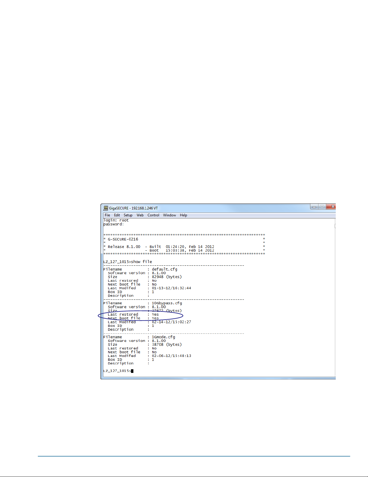
Saving Changes
The changes made in this chapter were mostly config system changes. These
changes are added to the active configuration right away and automatically saved in a
different location than the configuration files – there is no need to perform a config
save filename.cfg to save them.
However, it’s a good idea to get into the habit of using the config save filename.cfg
command. Later on, when you start setting up packet distribution with connections and
maps, your changes will added to the active configuration right away but won’t be
saved across a system reboot unless you use the config save filename.cfg command
to write your changes to flash.
OTE: The name of the factory-provided configuration file is default.cfg. You can see
N
the name of the most recently booted configuration file by using the show file
command and looking for the file with Last restored set to Yes.InFigure 5-6, you can
tell that the GigaSECURE node is currently operating with the 10Gbypass.cfg
configuration file and that this is also the configuration file that will be booted next (Next
boot file = Yes).
See Using Configuration Files on page 125 for details on using configuration files.
Figure 5-6: Showing Configuration Files
Basic GigaSECURE Connections and Configuration 59
Page 60

60 CLI User’s Guide
Page 61

Chapter 6
Connecting the G-SECURE-0216 to the Network
This section explains how to deploy the G-SECURE-0216 node on your
production network, including instructions on connecting the appliance inline
between two switches, connecting inline security tools to g1..g8 tool port
pairs, and opening the physical and logical bypasses so that traffic is
available to connected inline tools. See the following sections for details:
• Connecting the GigaSECURE Node to the Production Network on
page 62
• Connecting Inline Tools to the G-SECURE-0216 on page 70
• Identifying SFP+ and SFP Transceivers on page 70
61
Page 62
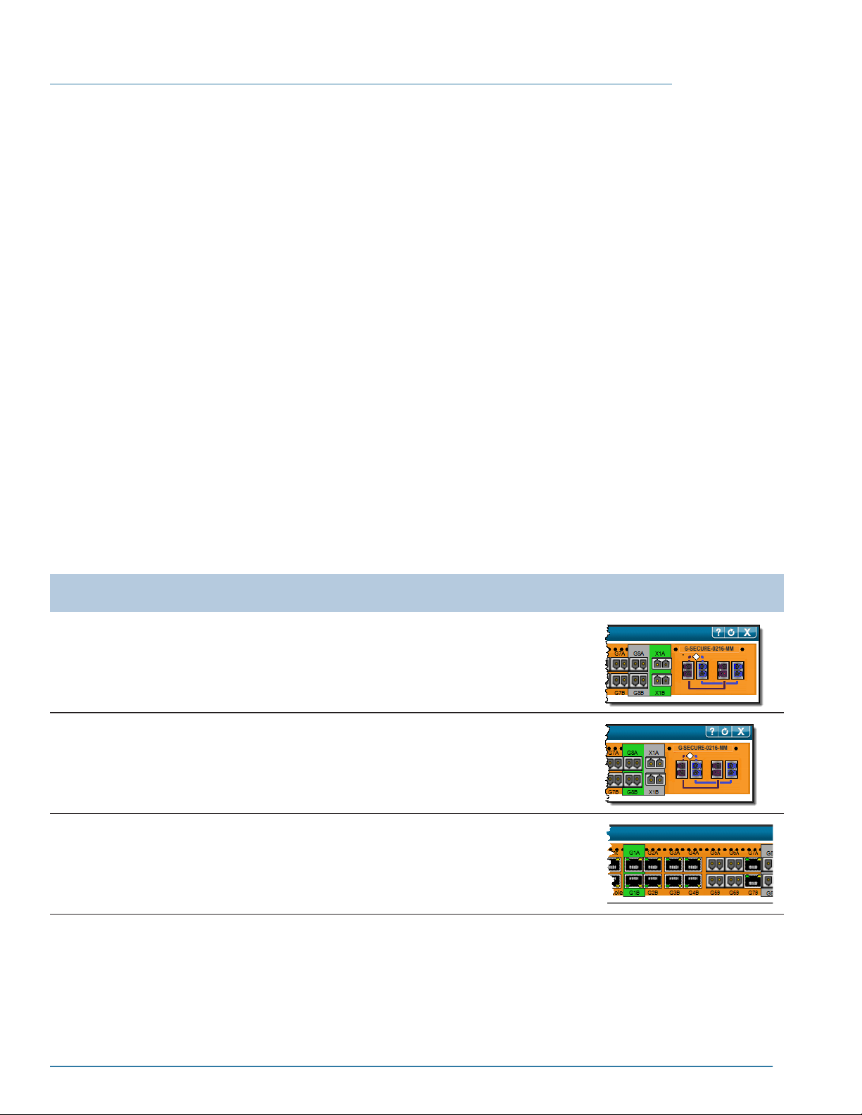
Connecting the GigaSECURE Node to the Production Network
Before cabling the G-SECURE-0216 to the production network, you need to consider
two questions:
• Are you connecting the G-SECURE to a 10G, 1G optical, or 1G electrical link?
The G-SECURE-0216 uses separate input ports for each speed and must have its
mode set to match in the CLI.
See Selecting the GigaSECURE Network Mode on page 62 for details.
• Do you plan to use the optical protection switch? The optical protection switch
provides failover protection. However, in the event of a power failure, high security
installations may not want to allow any uninspected packets into the network. In
addition, if you are using link status propagation features, the optical protection
switch should not be used (refer to Link Status Propagation and the Optical
Protection Switch on page 63).
See Sample G-SECURE-0216 Network Connections on page 64 for images showing
10G and 1G connections both with and without the use of the optical protection switch.
Selecting the GigaSECURE Network Mode
The GigaSECURE inline traffic distribution node can be connected inline to 10G, 1G
optical, or 1G electr ical network links – there are separate pairs of input ports for each
mode. Use the config network-mode <10 | 1 [electrical | optical] > command to
select the network speed and input ports to use:
Mode Description CLI Command G-VUE Chassis
Window Display
10G Mode The x1a/x1b ports are used as input ports, either
via fiber jumper cables from the A/B output ports on
the optical protection switch or direct connections
to the two sides of the network.
1G Optical
Mode
1G
Electrical
Mode
The g8a/g8b ports are used as input ports, either
via fiber jumper cables from the output ports on the
optical protection switch or direct connections to
the two sides of the network.
The g1a/g1b ports are used as input ports, either
via jumper cables from the output ports on the
optical protection switch or direct connections to
the two sides of the network.
config network-mode 10
config network-mode 1
optical
config network-mode 1
electrical
62 CLI User’s Guide
Page 63

Connect with or without Optical Protection Switch
The G-SECURE-0216 inline traffic distribution node can be connected to the network
either with or without the use of the optical protection switch module::
Using the GigaSECURE Node
with the Optical Protection
Switch
Using the GigaSECURE Node
without the Optical Protection
Switch
The two sides of the production network are connected to the
Network A and Network B ports on the optical protection switch
module. Jumper cables connect the A/B output ports on the
optical protection switch to the X1A/X1B (10G), G8A/G8B (1G
optical), or G1A/G1B (1G electrical) input ports.
The two sides of the production network are connected directly to
the input ports corresponding to the network speed and matching
GigaSECURE mode:
• 10G – x1a/x1b
• 1G Optical – g8a/g8b
• 1G Electrical – g1a/g1b
The optical protection switch provides the benefit of physical bypass failover – in the
event of a power outage, the optical protection switch automatically couples the fibers
between the inline network ports, removing the GigaSECURE switching fabric from the
link.
In most cases, this is the preferred method of deployment, ensuring link integrity in the
event of a power failure. However, some high-security sites may have policies requiring
that no packet enter the network without inspection by specific inline security tools. In
cases such as this, you can deploy the GigaSECURE inline traffic distribution node
without the optical protection switch – in the event of a power failure, packets will not be
able to pass in or out of the network.
Link Status Propagation and the Optical Protection Switch
The G-SECURE-0216 inline traffic distribution node can use link status propagation on
its network ports, forcing the link on the input network ports down in the following
situations:
• Link status failure on one of the network ports
• Link status failure on one of the connected tool port pairs
Link status propagation is useful in high availability environments because it notifies
upstream and downstream switches and firewalls of a problem on the opposite side of
the G-SECURE-0216 node, allowing them to fail over to a secondary security path.
Link status propagation features are only available on the input network ports – x1a/
x1b (10G), g8a/g8b (1G optical), or g1a/g1b (1G copper). They are not available on
the optical protection switch ports. Only use link status propagation in deployments
where the input network ports are directly connected to the network and not
connected via jumper cables to the optical protection switch.
Connecting the G-SECURE-0216 to the Network 63
Page 64

Sample G-SECURE-0216 Network Connections
The sections below illustrate cabling for the 10G and 1G modes both with and without
the use of the optical protection switch. Note that the diagrams all follow the convention
of using the A side of a port pair for the protected (internal) side of the networ k and the
B side for the unprotected (external) side of the network.
• 10G Mode with Optical Protection Switch
• 10G Mode without Optical Protection Switch
• 1G Optical Mode with Optical Protection Switch
• 1G Mode without Optical Protection Switch
64 CLI User’s Guide
Page 65
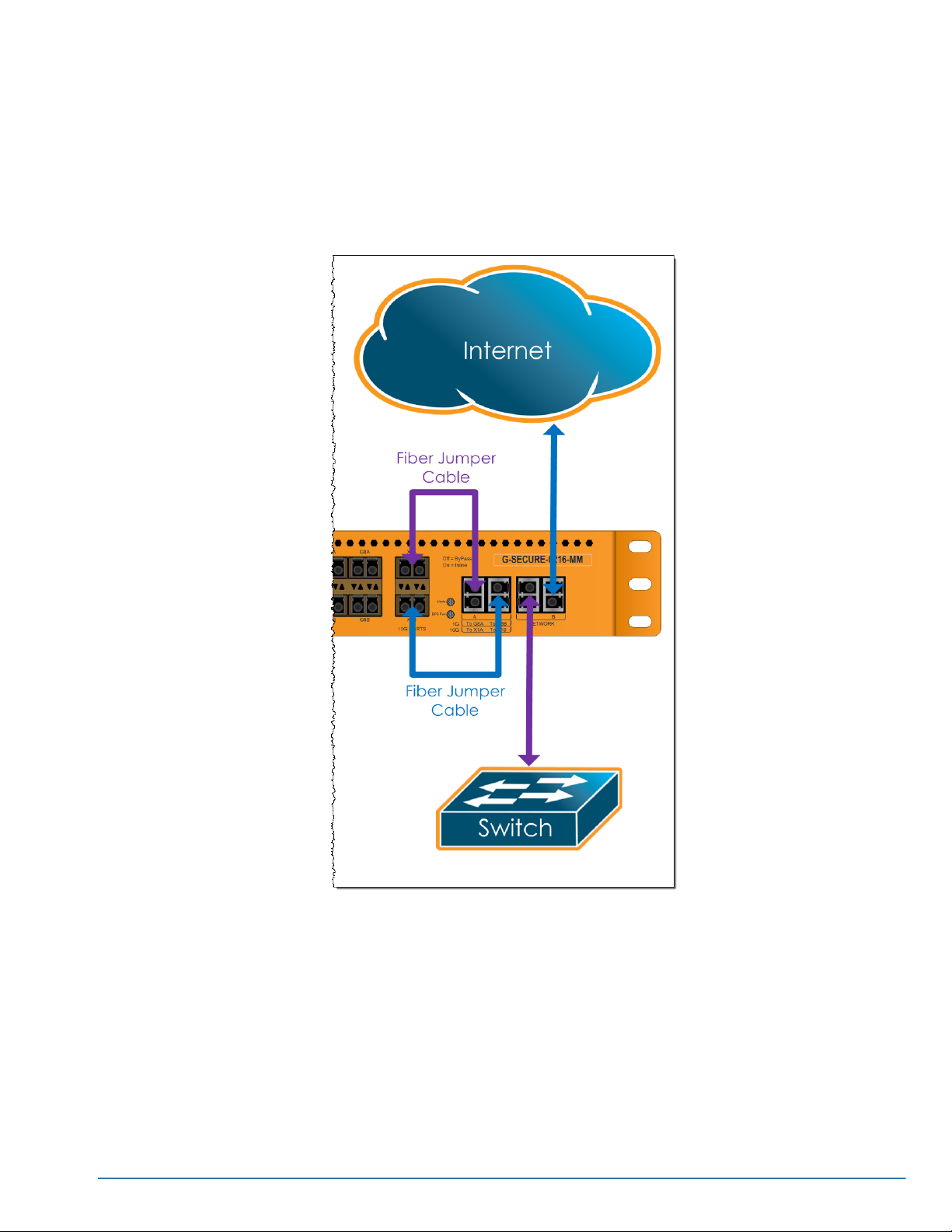
10G Mode with Optical Protection Switch
Fiber jumper cables provided with the GigaSECURE unit are used to cable the A/B
output ports on the optical protection switch module to the x1a/x1b input ports.
In the event of a power failure, the optical protection switch couples the fibers between
the Network A and Network B ports, providing failover protection.
Connecting the G-SECURE-0216 to the Network 65
Page 66
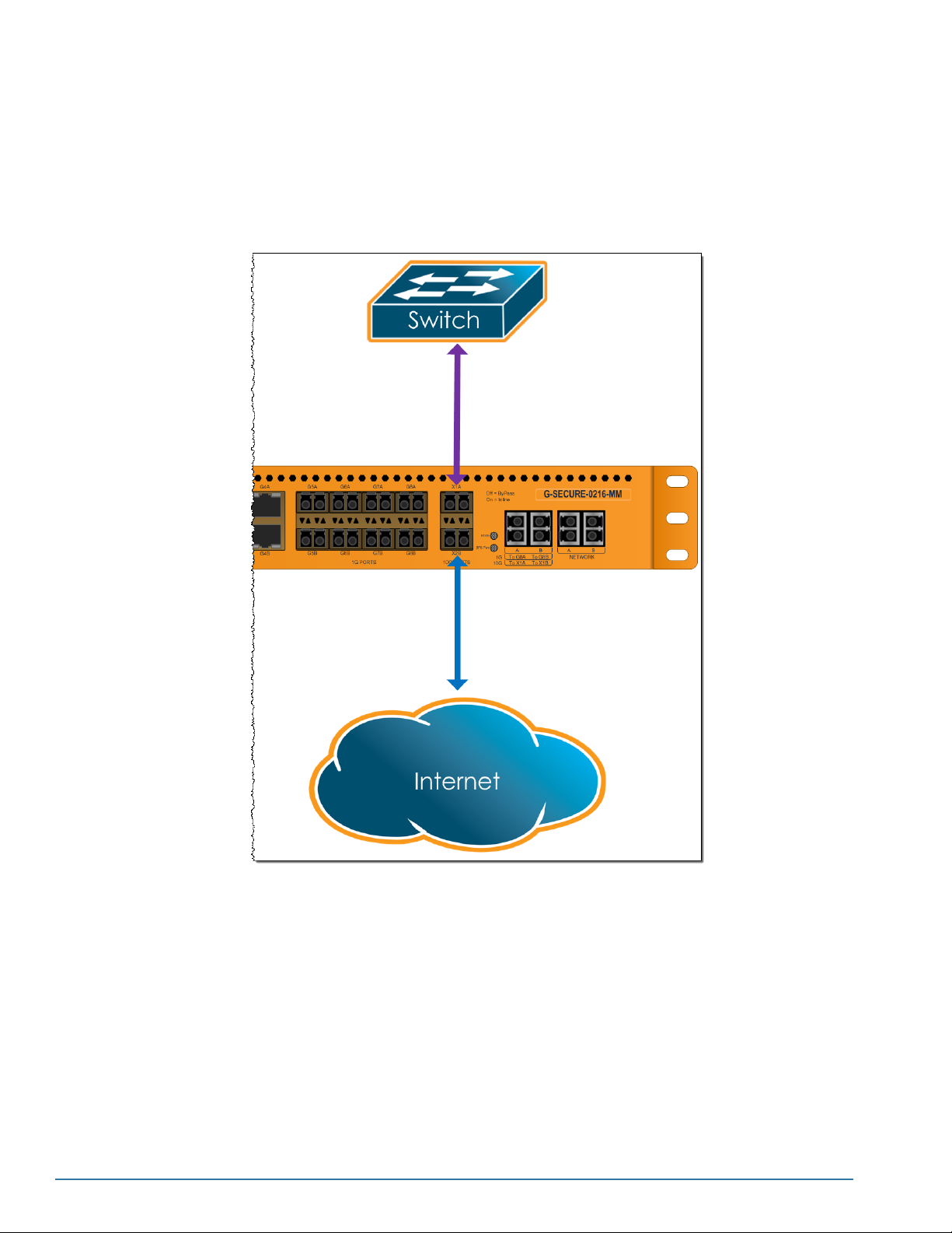
10G Mode without Optical Protection Switch
Both sides of the network are cabled directly to the x1a/x1b input ports.
This configuration is useful in high-security deployments, where uninspected packets
must never enter the network. In the event of a power outage, there is no physical
bypass – packets cannot pass through the appliance until power is restored.
66 CLI User’s Guide
Page 67
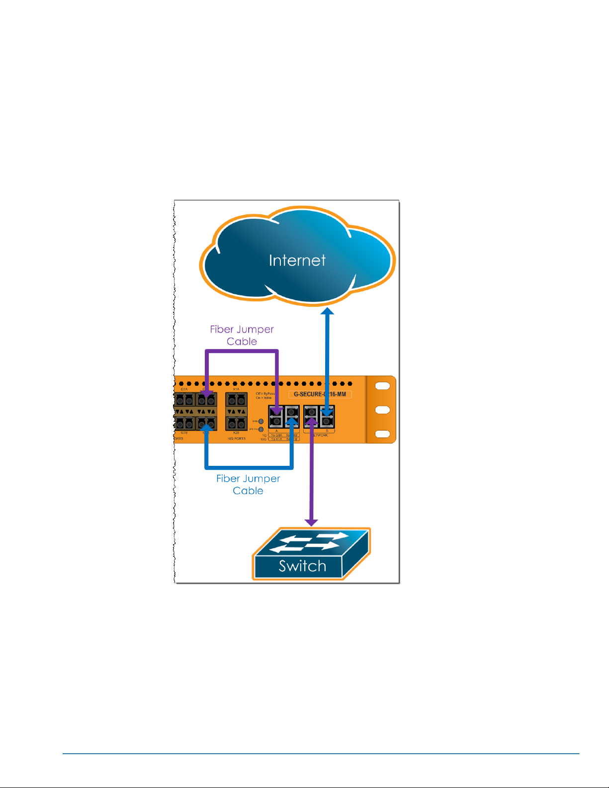
1G Optical Mode with Optical Protection Switch
Fiber jumper cables provided with the GigaSECURE unit are used to cable the A/B
output ports on the optical protection switch module to the g8a/g8b input ports.
You can also use this model with the g1a/g1b electrical input ports (config
network-mode 1 electrical).
In the event of a power failure, the optical protection switch couples the fibers between
the Network A and Network B ports, providing failover protection.
Connecting the G-SECURE-0216 to the Network 67
Page 68
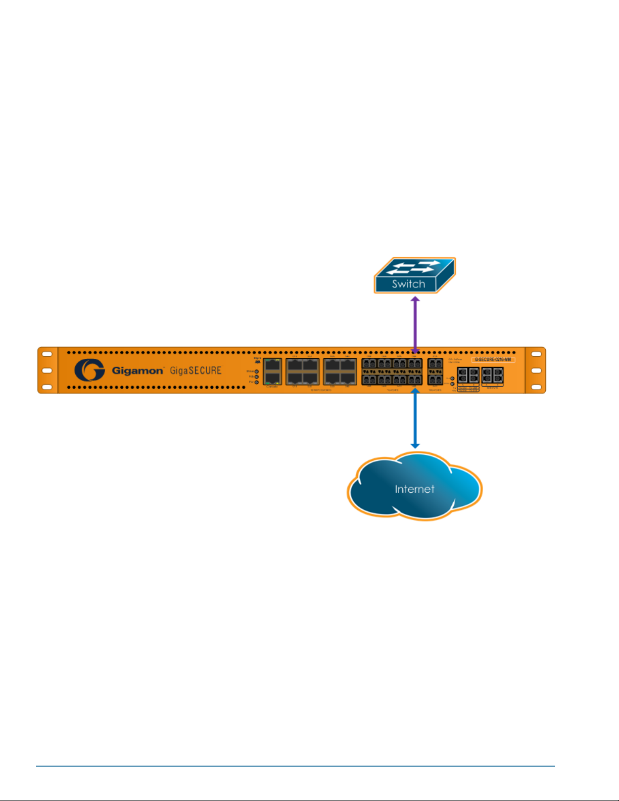
1G Mode without Optical Protection Switch
Both sides of the network are cabled directly to the g8a/g8b (optical mode; Figure 6-1)
or g1a/g1b (electrical mode; Figure 6-2) input ports on the G-SECURE-0216 node.
This configuration is useful in the following deployments:
• High-availability deployments, where link status propagation features are used to
force down the network or tool ports in the event of a failure and allow the traffic on
the opposite side of the GigaSECURE node to fail over to a secondary security
path.
• High-security deployments, where uninspected packets must never enter the
network. In the event of a power outage, there is no physical bypass – packets
cannot pass through the appliance until power is restored.
1G Optical – config network-mode 1 optical
Figure 6-1: 1G Optical Mode without the Optical Protection Switch
68 CLI User’s Guide
Page 69
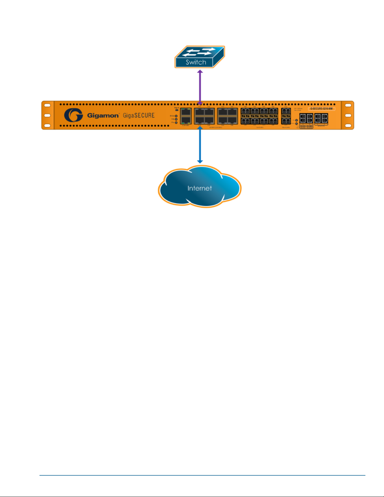
1G Electrical – config network-mode 1 electrical
Figure 6-2: 1G Electrical Mode without the Optical Protection Switch
Connecting the G-SECURE-0216 to the Network 69
Page 70

Connecting Inline Tools to the G-SECURE-0216
The G-SECURE-0216 appliance can distribute traffic arriving on its ingress ports to up
to eight 1G inline devices based on user-defined profiles – sets of packet-matching
criteria. You can distribute traffic based on IP or MAC addresses, as well as by
application port number (for example, 80/HTTP, 443/HTTPS, and so on).
Traffic can be sent to specific tools, load-balanced among groups of tools based on
matching IP flows, or a combination of both. In addition, a special collector destination
makes it easy to send all traffic not matching any bound profile either back onto the
network or to a specified tool.
Connect inline tools to any of the g1..g8 port pairs. Traffic sent to a given tool port pair
flows through the tool and then back onto the production network via the opposite port
in the pair. Use a tool port pair matching the media for your inline tool:
• Ports g1..g4 provide 10/100/1000 copper RJ-45 connectors.
• Ports g5..g8 use 1G optical SFP transceivers and support 1G speeds only. You can
use SX, LX, or ZX SFP transceivers – see Identifying SFP+ and SFP Transceivers
for information on supported transceivers.
• Follow the same cabling convention for all inline tools, using the A side for the
external (unprotected) side of the link and the B side for the internal (protected)
side.
Depending on the inline tool’s physical characteristics, you may need to adjust port
parameters on the G-SECURE-0216 unit. See config port-params commands for
details.
Identifying SFP+ and SFP Transceivers
Gigamon provides a variety of SFP+/SFP transceivers for use with the 10 Gb/1 Gb
ports in the GigaSECURE node. It is not always easy to tell the difference between
various SFP+/SFP transceivers. Use the following tips to keep track of your
transceivers:
• SFP+ transceivers use metal bail and latch assemblies. The color of the metal bail
corresponds to the SFP+ type, as summarized in the table below.
• 1 Gb SFP transceivers use either bail and latch assemblies with a colored plastic
sheath around the bail or assemblies made entirely of plastic (Sx SFP). The color
of the plastic sheath corresponds to the SFP type, as summarized in the table
below.
Transceiver Notes
IMPORTANT: Always use transceivers purchased from Gigamon to ensure
interoperability and performance.
• You can use the show port-params all command to see transceiver type
information for each of the network/tool ports in the GigaSECURE node. Check the
value of the Xcvr Type field for the ports in question.
70 CLI User’s Guide
Page 71
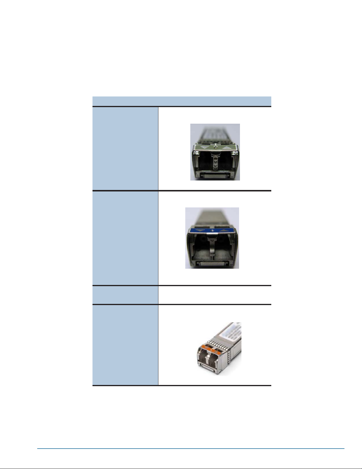
• Split ratios for external taps are as follows:
• 10 Gb – 50/50
• 1Gb– 70/30
•SeeAppendix C, GigaSECURE Transceiver Information (SFP/SFP+) for more
information on transceivers supported by the GigaSECURE node.
Media/Transceiver Description
10 Gb SR SFP+ Silver Metal Bail
10 Gb LR SFP+ Blue Metal Bail
10 Gb ER SFP+ Dark Red (Burgundy) Metal Bail
10 Gb LRM SFP+ Orange Metal Bail
Connecting the G-SECURE-0216 to the Network 71
Page 72
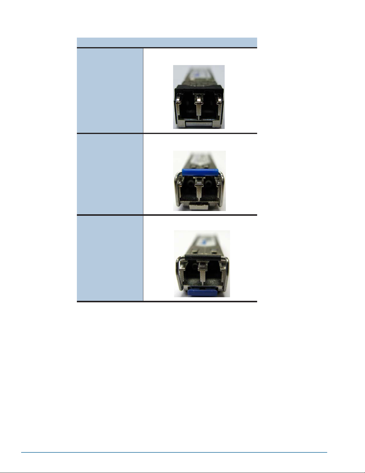
Media/Transceiver Description
1 Gb Sx SFP Black Plastic Bail
1 Gb Lx SFP Blue Plastic Sheath over Metal Bail
1 Gb Zx SFP Black Plastic Sheath over Metal Bail
72 CLI User’s Guide
Page 73

Configuring GigaSECURE Packet Distribution
This section introduces GigaSECURE packet distribution – what it is and how
you set it up.
N
OTE: The topics in this manual focus primarily on packet distribution in the
CLI, in addition to a wide variety of general topics. You can also manage
packet distribution in G-VUE. See the G-VUE User’s Guide and online help
for details.
The section includes the following major topics:
• About GigaSECURE Packet Distribution: Profiles and Distribution Rules
on page 73
Chapter 7
• Configuring GigaSECURE Traffic Distribution – Procedure on page 75
• Configuring Profiles
• Configuring Distribution Rules
• Configuring Heartbeat/Failover
• Opening the Physical and Logical Bypasses on page 103
About GigaSECURE Packet Distribution: Profiles and Distribution Rules
Packet distribution is where the GigaSECURE inline traffic distribution node’s
real power is on display – it’s where you decide which traffic arriving on
network ports should be sent to which inline tools, returning to the network
after inspection. Packets enter the G-SECURE-0216 10G ingress ports and
are distributed to up to eight 1G inline devices based on user-defined profiles
– sets of packet-matching criteria bound to network ports in distribution rules.
Distribution rules are like traffic cops for inline network ports, determining
which traffic goes to which inline tool ports. Traffic can be sent to specific
tools, load-balanced among groups of tools based on matching IP flows, or a
combination of both. In addition, a special collector destination makes it easy
to send all traffic not matching any bound profile either back onto the network
or to a specified tool.
The set of distribution rules in place on the GigaSECURE node is called the
distribution model. At any one time, there is only a single distribution model in
place on the GigaSECURE node, as set up with config distribution
command. See Configuring Distribution Rules on page 87 for details.
73
Page 74
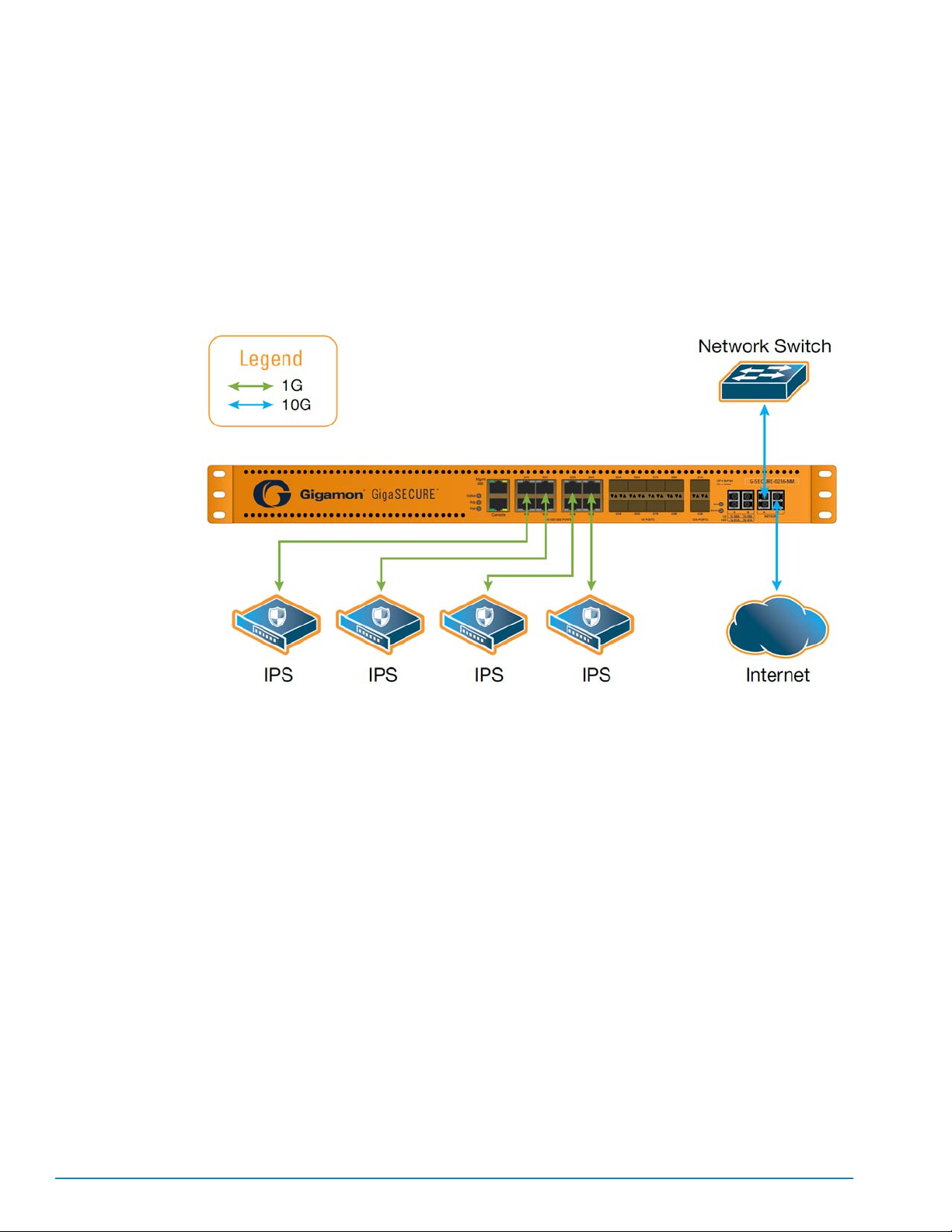
Deploying Inline Tools with the GigaSECURE Node
The GigaSECURE inline traffic distribution node enables flexible deployment of
security appliances such as firewalls and intrusion prevention systems. Devices such
as these are often connected inline to the network, with traffic flowing from the network
segment through the tool and then back onto the production network:
• Deploy multiple inline security appliances on a single link – firewalls, IPSs, NACs,
Web Filters, and so on, using distribution rules to ensure that each appliance sees
the traffic it is equipped to process.
• Monitor 10G data from inline links with 1G security and monitoring tools.
74 CLI User’s Guide
Page 75

Configuring GigaSECURE Traffic Distribution – Procedure
Configuring GigaSECURE traffic distribution consists of the following major steps:
1. Configure Profiles
2. Apply Profiles in
Distribution Rules
3. Configure Failover
Options for Tool Port
Pairs
A profile is a set of packet-matching criteria that can be used to identify
specific types of traffic. The GigaSECURE appliance provides a variety of
predefined profiles for common applications (HTTP, SSH, POP, and so on).
In addition, you can create your own profiles using a wide variety of Layer
2-4 criteria.
You use the config profile command to set up profiles.
See Configuring Profiles for details.
Once you have configured profiles to match specific network traffic, you
can bind them to the GigaSECURE node’s input ports in a set of
distribution rules called a distribution model.
Distribution rules consist of one or more profiles sending traffic arriving on
input ports to specific inline tools. Distribution r ules can be applied to traffic
flowing in either or both directions on the GigaSECURE node’s input ports.
In addition, they can send traffic to specific inline tools or to a
load-balanced group of inline tools.
You use the config distribution command to set up the GigaSECURE
node’s distribution model. See Configuring Distribution Rules for details.
The GigaSECURE appliance provides failover protection for inline tool port
pairs and load-balanced groups, allowing you to specify how the appliance
handles failure conditions.
You can configure failover detection differently for individual ports and
load-balanced groups. In addition, when configuring failover for
load-balanced groups, you can configure how traffic is handled when one
tool in a group of load-balanced tools fails, either failing over to the next
configured port or rebalancing over all ports in the group. You can also
specify whether to force the network ports down if one of the tool ports or
tool groups fails.
You use the config failover command to set up the GigaSECURE node’s
failover settings. See Configuring Heartbeat/Failover for details.
4. Open Physical Bypass
and Set Logical Bypass
to Conditional
Once you have set up your distribution model and configured failover
options, you’re ready to open up the physical and logical bypasses so that
traffic arriving on the input ports is available to the GigaSECURE switching
fabric. See Opening the Physical and Logical Bypasses for details.
Configuring GigaSECURE Packet Distribution 75
Page 76
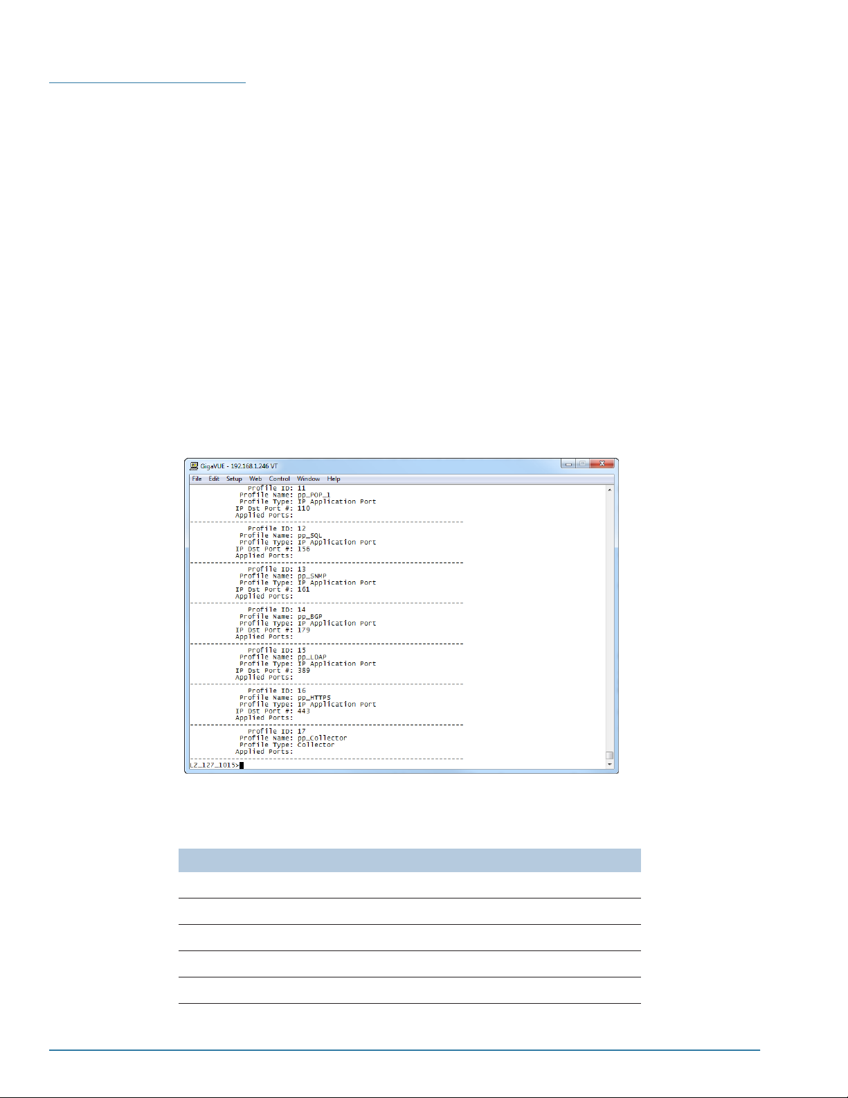
Configuring Profiles
You use the config profile command to set up profiles – sets of packet-matching
criteria that can be used to identify specific types of traffic. Once a profile has been
defined, it can be applied to the input ports on the GigaSECURE appliance in a
distribution rule, forwarding matching traffic to specific inline tools.
Profiles exist as independent entities that can be bound to a GigaSECURE network
port in a distribution rule with the config distribution command. You can use the
factory-configured profiles, create your own custom profiles, or, most likely, use a
combination of both.
Reviewing the Factory-Configured Profiles
The GigaSECURE appliance provides a variety of predefined profiles for common
applications (HTTP, SSH, POP, and so on). You can review the preconfigured profiles
with the show profile factory command. In response, the CLI will show you the
factory-configured profiles with a summary of their settings (Reviewing the
Factory-Configured Profiles on page 76).
Figure 7-1: Reviewing the Factory-Configured Profiles
The table below summarizes the settings for each of the factory-configured profiles:
Factory Profile Name Settings
pp_FTP_0 IP Destination Port = 20
pp_FTP_1 IP Destination Port = 21
pp_SSH IP Destination Port = 22
pp_Telnet IP Destination Port = 23
pp_SMTP IP Destination Port = 25
76 CLI User’s Guide
Page 77

Factory Profile Name Settings
pp_DNS IP Destination Port=53
pp_TFTP IP Destination Port= 69
pp_HTTP_0 IP Destination Port = 80
pp_HTTP_1 IP Destination Port = 8080
pp_POP_0 IP Destination Port = 109
pp_POP_1 IP Destination Port = 110
pp_SQL IP Destination Port = 156
pp_SNMP IP Destination Port = 161
pp_BGP IP Destination Port = 179
pp_LDAP IP Destination Port = 389
pp_HTTPS IP Destination Port = 443
pp_Collector Collector
Creating Custom Profiles with config profile
You use the config profile command to set up application-aware profiles for the
GigaSECURE node. The syntax is as follows:
config profile
[dscp <assured-forwarding-value>]
((af11~af13, af21~af23, af31~af33, af41~af43, ef)
[ethertype <2-byte-hex>]
[ipfrag <0|1|2|3|4>]
(0:no frag, 1:1st frag, 2:no frag or 1st frag, 3:frag but not 1st, 4:all frag)
[ipdst <dstaddr>] [ipdstmask <xxx.xxx.xxx.xxx | /nn>]
[ipsrc <srcaddr>] [ipsrcmask <xxx.xxx.xxx.xxx | /nn>]
[ip6src <srcaddr>] [ip6srcmask <xxxx::xxxx | /nn>]
[ip6dst <dstaddr>] [ip6dstmask <xxxx::xxxx | /nn>]
[ip6fl <3-byte-hex>]
[ipver <4|6>]
[macdst <macaddr>] [macdstmask <6-byte-hex>]
[macsrc <macaddr>] [macsrcmask <6-byte-hex>]
[portdst <single-port-number> | <x..y>] [even | odd] (valid range 0..65535)
[portsrc <single-port-number> | <x..y>] [even | odd] (valid range 0..65535)
[protocol <gre|icmp|igmp|ipv4ov4|ipv6ov4|rsvp|tcp|udp|<1-byte-hex>>]
[tcpctl <1-byte-hex>] [tcpctlmask <1-byte-hex>]
[tosval <1-byte-hex>]
[ttl <0~255> | <x..y>] (valid range 0..255)
[uda1_data <16-byte-hex>] [uda1_mask <16-byte-hex>]
[uda2_data <16-byte-hex>] [uda2_mask <16-byte-hex>]
[vlan <1~4094> | <x..y>] [even | odd]
[alias <string>]
The table below lists and describes the available criteria in the Profile Editor. Note that
these are the same criteria available for profiles in G-VUE.
Configuring GigaSECURE Packet Distribution 77
Page 78

Argument Description
[dscp <assured-forwarding-value>]
(af11~af13, af21~af23, af31~33, af41~43, ef)
Creates a pattern for a particular decimal DSCP value. You can choose
any value within the four Assured Forwarding class ranges or ef for
Expedited Forwarding (the highest priority in the DSCP model).
The valid DSCP values by Assured Forwarding Class are as follows:
• Class 1 – 11, 12, 13
• Class 2 – 21, 22, 23
• Class 3 – 31, 32, 33
• Class 4 – 41, 42, 43
• Expedited Forwarding –ef
For example, config profile dscp ef will match all traffic with expedited
forwarding assigned.
[ethertype <2-byte-hex>]
[ipfrag <0|1|2|3|4>]
[ipdst <dstaddr>] [ipdstmask <xxx.xxx.xxx.xxx | /nn>]
[ipsrc <srcaddr>] [ipsrcmask <xxx.xxx.xxx.xxx | /nn>]
Creates a filter pattern for the Ethertype value in a packet (for example,
config filter allow ethertype 0x86DD will match all traffic with an IPv6
Ethertype.
NOTE: To filter for VLANs, use the predefined VLAN criterion instead
of the 8100 Ethertype.
Creates a profile for different types of IPv4 fragments:
• 0 – Matches unfragmented packets.
• 1 – Matches the first fragment of a packet.
• 2 – Matches unfragmented packets or the first fragment of a packet.
• 3 – Matches all fragments except the first fragment in a packet.
• 4 – Matches any fragment.
For example, config profile ipfrag 1 alias headerfrags creates a filter
named headerfrags that matches the first fragment in a packet.
NOTE:The ipfrag argument only matches IPv4 fragments. To create a
filter for IPv6 fragments, set ipver to 6 and use the protocol argument
with a <1-byte-hex> value of 0x2c. This has the same effect as option
number 4 for IPv4 – it matches all IPv6 fragments. For example:
config profile ipver 6 protocol 0x2c alias six_frags
Creates a filter for either a source or destination IPv4 address or
subnet.
Use subnet masks to match traffic from a range of IP addresses. You
can enter subnet masks using either dotted-quad notation
(<xxx.xxx.xxx.xxx>) or in the bit count format.
Note that subnet masks used in IP filters do not need to begin from the
start of the address, nor do masked bits need to be contiguous. For
example, the GigaSECURE node will accept a subnet mask where the
masked bits start in the third octet, as follows – 0.0.255.255.
78 CLI User’s Guide
Page 79

Argument Description
[ip6src <srcaddr>] [ip6srcmask <xxxx::xxxx | /nn>]
[ip6dst <dstaddr>] [ip6dstmask <xxxx::xxxx | /nn>]
Creates a filter for either a source or destination IPv6 address or
subnet. Enter IPv6 addresses as eight 16-bit hexadecimal blocks
separated by colons. For example:
2001:0db8:3c4d:0015:0000:0000:abcd:ef12
Use subnet masks to match traffic from a range of IP addresses. You
can enter subnet masks either in 16-bit hexadecimal blocks separated
by colons or in the bit count format.
Note that subnet masks used in IP filters do not need to begin from the
start of the address, nor do masked bits need to be contiguous. For
example, the GigaSECURE node will accept a subnet mask where the
masked bits start in the third octet, as follows – 0.0.255.255.
[ip6fl <3-byte-hex>]
[ipver <4|6>]
[macdst <macaddr>] [macdstmask <6-byte-hex>]
[macsrc <macaddr>] [macsrcmask <6-byte-hex>]
Creates a filter for the 20-bit Flow Label field in an IPv6 packet. Packets
with the same Flow Label, source address, and destination address
are classified as belonging to the same flow. IPv6 networks can
implement flow-based QoS using this approach.
Specify the flow label as a 3-byte hexadecimal pattern. Note, however,
that only the last 20 bits are used – the first four bits must be zeroes
(specified as a single hexadecimal zero in the CLI). For example, to
match all packets without flow labels, you could use the following filter:
config profile ip6fl 0x000000 alias no_flow
Alternatively, to match the flow label of 0x12345, you could use the
following:
config profile ip6fl 0x012345 alias flow12345
When used by itself, the ipver argument creates a filter to match either
all IPv4 or all IPv6 traffic.
You can also set ipver to 6 and use it together with other arguments to
change their meaning. See IPv4/IPv6 and Profile Criteria on page 83
for more information on ipver.
NOTE: The ipver argument is implicitly set to 4 – if you configure a
filter without ipver specified, the GigaSECURE node assumes that the
IP version is 4.
Creates a filter pattern for either a source or destination MAC address.
Use the optional macsrcmask or macdstmask argument to create a
range of MAC addresses that will satisfy the filter pattern.
NOTE: You can enter hexadecimal MAC addresses in either
0xffffffffffff or ffffffffffff format.
[portdst <single-port-number> | <x..y>] [even | odd]
[portsrc <single-port-number> | <x..y>] [even | odd]
Creates a filter for a source or destination application port. You can
also specify:
• A range of ports. For example config profile portsrc 5000..5100
will match all source ports from 5000 to 5100, inclusive.
• Either odd or even port numbers. The even|oddarguments are
useful when setting up filters for VoIP traffic. Most VoIP
implementations send RTP traffic on even port numbers and RTCP
traffic on odd port numbers.
For example, config profile portsrc 5000..5100 odd will match all
odd source ports between 5000 and 5100.
Configuring GigaSECURE Packet Distribution 79
Page 80

Argument Description
[protocol <gre|icmp|igmp|ipv4ov4|ipv6ov4|rsvp|tcp|
udp|<1-byte-hex>>]
Creates a filter for a particular protocol. The exact filters available
depend on the GigaSECURE platform, as shown at left.
For example, config profile protocol gre will create a filter that
excludes all GRE traffic.
Protocol Filters and IPv6
The predefined criteria available for IPv4 (GRE, RSVP, and so on) are
not allowed when ipver is set to 6. This is because with the next
header approach used by IPv6, the next layer of protocol data is not
always at a fixed offset as it is in IPv4.
To address this, the GigaSECURE node provides the <1-byte-hex>
option to match against the standard hex values for these protocols in
the Next Header field. Here are standard 1-byte-hex values for both
IPv4 and IPv6:
0x00: Hop-By-Hop Option (v6 only)
0x01: ICMP (v4 only)
0x02: IGMP
0x04:IPoverIP
0x06: TCP
0x11: UDP
0x29: IPv6 over IPv4
0x2b: Routing Option (v6 only)
0x2c: Fragment (v6 only)
0x2E: RSVP (v4 only)
0x2F: GRE (v4 only)
0x32: Encapsulation Security Payload (ESP) Header (v6 only)
0x33: Authentication (v6 only)
0x3a: ICMP (v6 only)
0x3b: No Next Header (v6 only)
0x3c: Destination Option (v6 only)
[tcpctl <1-byte-hex>] [tcpctlmask <1-byte-hex>]
Creates a one-byte pattern match filter for the standard TCP control
bits (URG, SYN, FIN, ACK, and so on). You can use the tcpctlmask
argument to specify which bits should be considered when matching
packets.
See Configuring Profiles for TCP Control Bits on page 82 for a list of
the hexadecimal patterns for each of the eight TCP flags, along with
some examples.
80 CLI User’s Guide
Page 81

Argument Description
[tosval <1-byte-hex>]
Creates a filter pattern for the Type of Service (TOS) value in an IPv4
header. The TOS value is how some legacy IPv4 equipment
implements quality of service traffic engineering. The standard values
are:
• Minimize-Delay: Hex 0x10 or 10
• Maximize-Throughput: Hex 0x08 or 08
• Maximize-Reliability: Hex 0x04 or 04
• Minimize-Cost: Hex 0x02 or 02
• Normal-Service: Hex 0000 or 00
NOTE: Most network equipment now uses DSCP to interpret the TOS
byte instead of the IP precedence and TOS value fields.
[ttl <0~255> | <x..y>] (valid range 0..255)
[uda1_data <16-byte-hex>] [uda1_mask <16-byte-hex>]
[uda2_data <16-byte-hex>] [uda2_mask <16-byte-hex>]
Creates a filter for the Time to Live (TTL – IPv4) or Hop Limit (IPv6)
value in an IP packet.
• If there is no ipver argument included in the filter (or if it is set to 4),
the GigaSECURE node matches the value against the TTL field in
IPv4 packets.
•Ifipver is set to 6 in the filter, the GigaSECURE node matches the
value against the Hop Limit field in IPv6 packets.
The TTL and Hop Limit fields perform the same function, specifying the
maximum number of hops a packet can cross before it reaches its
destination.
Creates up to two user-defined, 16-byte pattern matches in a filter. A
pattern is a particular sequence of bits at a specific offset from the start
of a frame.
Setting a user-defined pattern match consists of the following major
steps:
• Specify the two global offsets to be used for user-defined pattern
matches using the config uda command (uda1_offset and
uda2_offset)
• Specify the data pattern and mask using the config profile
command with the [udax_data][udax_mask] arguments. You use
the mask to specify which bits in the pattern must match to satisfy
the filter.
A single filter can contain up to two user-defined pattern matches.
NOTE: Always use the predefined filter elements instead of
user-defined pattern matches when possible.
See Working with User-Defined Pattern Matches on page 83 for
details.
[vlan <vlan id (1-4094)> | <x..y>] [odd | even]
[alias <string>]
Creates a filter pattern for a VLAN ID or range of VLAN IDs. You can
also use the odd | even argument to match alternating VLAN IDs. For
example, config profile vlan 200..300 even will match all even VLAN
IDs between 200 and 300.
Use the alias argument to associate a textual alias with a profile.
Aliases are optional. The GigaSECURE node automatically creates a
Filter ID for every profile you configure. You can manage profiles either
by the automatically generated numerical Filter ID or by the optional
alias.
NOTE: The easiest way to discover the automatically generated ID for
a given profile is to do a show profile command in the CLI. Each filter
will be shown along with its numerical ID.
Configuring GigaSECURE Packet Distribution 81
Page 82

GigaSECURE Profile Logic
When working with profiles, you can easily combine multiple criteria into a single profile
rule by combining them in the CLI command. Within a single profile, criteria are joined
with a logical AND. A packet must match each of the specified criteria to satisfy the
profile.
OTE: When used in a profile with multiple criteria, the ipver argument changes the
N
interpretation of some filter arguments. See IPv4/IPv6 and Profile Criteria on page 83
for details.
Configuring Profiles for TCP Control Bits
As described in the table above, you can use the tcpctl argument to set one-byte
pattern profile criteria for the standard TCP control bits. The table below summarizes
the bit positions of each of the flags, along with their corresponding hexadecimal
patterns.
Flag Bit Position Pattern TCP Control
Mask
Examples
Congestion Window
Reduced
ECN Echo .X.. .... 0x40 0x3f
Urgent Pointer ..X. .... 0x20 0x3f
Acknowledgment ...X .... 0x10 0x3f
Push .... X... 0x08 0x3f
Reset .... .X.. 0x04 0x3f
SYN .... ..X. 0x02 0x3f
FIN .... ...X 0x01 0x3f
X... .... 0x80 0x3f
The following filter matches packets with only the SYN bit set:
config profile tcpctl 0x02 tcpctlmask 0x3f alias syns_only
Many packets will have some combination of these bits set rather than just one. So, for
example, the following filter matches all packets with both the ACK and SYN bits set:
config profile tcpctl 0x12 tcpctlmask 0x3f alias syns_acks
82 CLI User’s Guide
Page 83

IPv4/IPv6 and Profile Criteria
The GigaSECURE node provides a variety of profile criteria specific to IPv6 traffic,
including:
IPv6 Entity
IPv6 Source/Destination Addresses
IPv6 Flow Labels
IPv6 Traffic
In addition to the explicit IPv6 profile criteria listed above, you can use the ipver
argument to change how some of the other criteria are interpreted.
When ipver is used by itself in a profile, it returns all traffic matching the specified IP
version, 4 or 6. However, when ipver is set to 6, several of the other arguments are
interpreted differently when used in the same profile, as summarized below:
argument ipver set to 4 (or not specified) ipver set to 6
portsrc/portdst
protocol
Matches all IPv4 traffic on the
specified port number.
NOTE: Because of this, if you wanted to match all IPv4 and IPv6 traffic on a
particular destination port (say, 500), you would need to construct two profiles
– one for IPv4 and one for IPv6.
When used with the <1-byte-hex>
argument, matches against the
protocol field in the standard IPv4
header.
Matches all IPv6 traffic on the
specified port number.
When used with the <1-byte-hex>
argument, matches against the Next
Header field in the standard IPv6
header.
NOTE: These fields perform essentially the same service in both versions,
specifying what the next layer of protocol is. However, they have different
names and are found at different locations in the header. See IPv4/IPv6 and
Profile Criteria for a list of useful values for the <1-byte-hex> field.
Matches against the standard TTL
(time-to-live) field in the IPv4 header.
ttl
Matches against the standard Hop
Limit field in the IPv6 header.
NOTE: These fields perform essentially the same service in both versions,
specifying how long a datagram can exist.
OTE: The ipver argument is implicitly set to 4 – if you configure a profile without IP
N
Version specified, the GigaSECURE appliance assumes that the IP version is 4.
Working with User-Defined Pattern Matches
The GigaSECURE appliance lets you create pattern match filters to search for a
particular sequence of bits at a specific offset in a packet. You can configure up to two
user-defined, 16-byte pattern matches in a filter or map-rule. A pattern is a particular
sequence of bits at a specific location in a frame.
Configuring GigaSECURE Packet Distribution 83
Page 84

N
OTE: See User-Defined Pattern Match Examples for step-by-step instructions on
creating a real-world pattern-match filter.
N
OTE: Both the CLI and G-VUE refer to a pattern as a UDA (“user-defined attribute”).
The major steps in setting up a user-defined pattern match in G-VUE are as follows.
Step Description
Configure Global
Offsets
Use the config uda option to set up the GigaSECURE node’s global offsets for user-defined pattern
matches.
You can set the two offsets at 4-byte boundaries from 2-110 bytes, resulting in a data range of 2-126
bytes. The offsets can not overlap. There are only two offsets in place on the system at any one time –
the same offsets are used by all pattern-based filters and map-rules.
IMPORTANT: Changing the global UDA offsets will affect all UDA-based filters/map-rules already in
place on the GigaSECURE system! It’s a good idea to review any UDA-based por t-filters or map-rules
already in place before you change the UDA offsets.
Configure Patterns
and Masks
Use the uda1_data/uda1_mask and uda2_data/uda2_mask arguments for the config filter and
config map-rule commands to set up the actual patterns and masks.
See User-Defined Pattern Match Examples for details.
User-Defined Pattern Match Syntax
This section describes the syntax for the commands used to set up user-defined
pattern match filters and map-rules:
• Specifying Offsets – config uda on page 84
• Specifying Patterns and Masks – config udax_data/udax_mask on page 85
Specifying Offsets – config uda
You use the config uda command to specify the two global offsets to be used for
user-defined pattern matches. This command has the following syntax:
config uda [uda1_offset <2~110>] [uda2_offset <2~110>]
The GigaSECURE appliance accepts offsets at four-byte boundaries ranging from byte
2 to byte 110. This means that there are 27 valid offset positions ranging from 0x02 (an
offset of 2 bytes) to 0x6d (an offset of 110 bytes). Offsets are always frame-relative, not
data-relative.
In many cases, you will be looking for patterns that do not start exactly on a four-byte
boundary. To search in these position, you would set an offset at the nearest four-byte
boundary and adjust the pattern and mask accordingly.
Default Offsets
The default offsets are listed below. You can always see the current offset values by
using the show uda command.
Offset Default Value
uda1_offset 14 (decimal); E (hexadecimal)
84 CLI User’s Guide
Page 85

Offset Default Value
uda2_offset 30 (decimal); 1E (hexadecimal)
Specifying Patterns and Masks – config udax_data/udax_mask
The user-defined pattern match syntax is identical for filters and map-rules:
[uda1_data <16-byte-hex>] [uda1_mask1 <16-byte-hex>]
[uda2_data <16-byte-hex>] [uda2_mask2 <16-byte-hex>]
• Both the udax_data and udax_mask arguments are specified as sixteen-byte
hexadecimal sequences. Specify the pattern in four four-byte segments separated
by hyphens. For example:
0x01234567-89abcdef-01234567-89abcdef
• Masks specify which bits in the pattern must match. The mask lets you set certain
bits in the pattern as wild cards – any values in the masked bit positions will be
accepted.
• Bits masked with binary 1s must match the specified pattern.
• Bits masked with binary 0s are ignored.
User-Defined Pattern Match Rules
Keep in mind the following rules when creating user-defined pattern matches:
• Offsets are specified in decimal; patterns and masks are specified in hexadecimal.
• All hexadecimal values must be fully defined, including leading zeroes. For
example, to specify 0xff as a 16-byte value, you must enter
00000000-00000000-00000000-000000ff.
• User-defined pattern-match criteria are only allowed in network port-filters and
single-tool map-rules. They are not allowed in tool port-filters or multi-tool maps.
• You can use up to two separate user-defined pattern matches in a single profile.
When two user-defined pattern matches appear in the same profile, they are joined
with a logical AND. However, note that the two patterns cannot use the same offset.
• Avoid using user-defined pattern matches to filter for elements that are available as
predefined filters (for example, IP addresses, MAC addresses, and so on).
User-Defined Pattern Match Examples
Suppose you want to set up a filter that matches all traffic with MPLS label 23
(0x00017). To do this, you can use a filter that combines an ethertype filter for the
MPLS ethertype (8847) with a user-defined pattern match for the label itself.
The ethertype filter for MPLS does two things:
• Ensures that the filter matches MPLS traffic.
• Assures us that all traffic accepted by the filter will have an MPLS label stack
starting at an offset of 14 bytes (right after the DLC header).
Configuring GigaSECURE Packet Distribution 85
Page 86
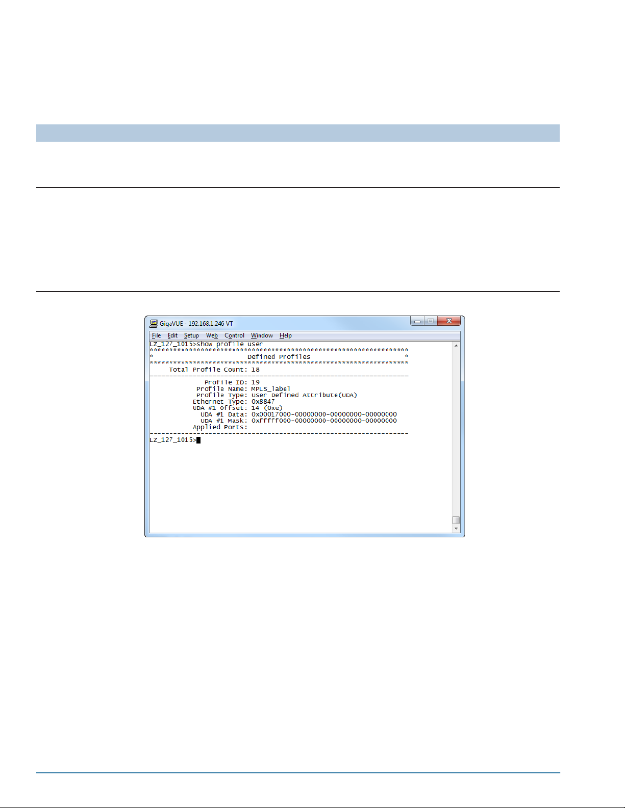
We’ll put the ethertype argument in the same filter with the user-defined pattern match
to make sure they’re joined with a logical AND. The following example explains how to
construct this filter. Figure 7-2, below, shows the filter in the GigaSECURE CLI.
Description Command
First, set the offset for the first user-defined pattern match.
We know that MPLS label stacks start at an offset of 14 bytes, right
after the DLC header, so let’s set that up.
config uda uda1_offset 14
Next, set up the profile itself. The profile will have two parts – the
ethertype criteria and the user-defined pattern match itself.
• The ethertype for MPLS is 0x8847.
• We’re searching for the MPLS label of 23 (0x00017). Fortunately, the
offset of 14 is on a four-byte boundar y when counting from the start
of the valid range (2~110; so, 2, 6, 10, 14). This makes it easy to
supply the pattern – we can start with the actual MPLS label and
then mask the rest with binary zeroes.
config profile ethertype 0x8847 uda1_data
0x00017000-00000000-00000000-00000000 uda1_mask
0xfffff000-00000000-00000000-00000000 alias
MPLS_label
Figure 7-2: Sample User-Defined Pattern Match Profile
86 CLI User’s Guide
Page 87
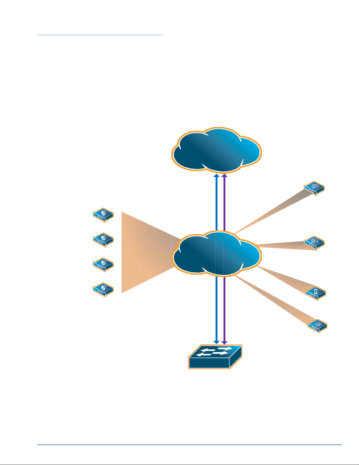
Configuring Distribution Rules
You use the config distribution command to specify which portions of the traffic
flowing over the inline network ports are sent to which inline tools. The config
distribution command creates a distribution model – a set of distribution-rules sending
matching traffic to specific inline tools or load-balanced groups of tools. At any one
time, there is only a single distribution model in place on the GigaSECURE node, as
set up with config distribution.
Each distribution-rule includes one or more profiles – sets of packet-matching criteria –
and a destination for the matching traffic. The figure below illustrates this concept.
1G IPS
Internet
distribution
-rule
Firewall
1G IPS
1G IPS
1G IPS
distribution-rule
GigaSECURE
config distribution
Switch
distribution-rule
distribution-
rule
distribution-rule
Firewall
NAC
NAC
Configuring GigaSECURE Packet Distribution 87
Page 88

Syntax for config distribution
The syntax for the config distribution command is as follows:
config distribution <distribution-rule> ... <distribution-rule>
<distribution-rule> = profile <profile-name> tool <port>|<port-list>
The config distribution command syntax is deceptively simple – each rule includes
the following components created by the profile selections and tool port destinations:
Component Description
Profile(s)
Specify the packet-matching profiles to be used as part of the distribution rule. Distribution rules consist of one
or more profiles designed to match specific packet criteria – all HTTP packets, all SSH packets, packets on a
particular set of VLANs, packets destined to a particular IP address, and so on.
You can select from predefined profiles provided with the GigaSECURE appliance or create your own custom
profiles in the Profile Editor (see Configuring Profiles for details).
Distribution Rule Logic
Profiles selected for a distribution rule are joined with a logical OR – packets satisfying any of the profiles in the
rule will be sent to the specified destination.
Keep in mind, however, that criteria in a given profile are joined with a logical AND – a packet must match ALL
criteria in a profile to match.
Distribution Rule Priority
Keep in mind that packets are sent to the first matching rule in the Distribution Info list. It’s not uncommon for a
packet to match multiple rules – keep in mind that such packets will be sent to the destination specified by the
first matching rule in the list. You can use the Priority buttons in the Distribution Info list to adjust the order in
which rules are considered.
Directionality
for
Destinations
Creation of
Load
Balanced
Groups
Each distribution rule includes a destination – where the GigaSECURE unit will send matching packets.
Distribution-rules can use any of the following destinations depending on how you define tool argument:
• Unidirectional inline tool port (for example, g1a)
• Bidirectional inline tool port pair. For example, a destination of g1 indicates that traffic matching the specified
profiles is sent to both g1a and g1b.
• Load-balanced group of unidirectional inline tool ports. For example, g1a..g4a. Note that all unidirectional
tool ports in a group must flow in the same direction, either AtoBor BtoA.
• Load-balanced group of bidirectional inline tool ports.
Load balanced groups are useful when the traffic on a link is more than an existing 1G tool can handle. You can
connect multiple instances of the same tool to separate inline tool ports and use the GigaSECURE to distribute
load-balanced traffic among them. Traffic is distributed based on source/destination IP addresses/ports,
ensuring that packets belonging to a particular flow go to the same destination within the group.
The GigaSECURE appliance can use a combination of these approaches, with some distribution rules sending
traffic to specific inline tool port and others sending traffic to a load-balanced group.
The config distribution command’s tool <port-list> argument implicitly creates a load-balanced group. Any
time you specify multiple ports as the destination for packets matching a particular profile, you are creating a
load-balanced group, whether it’s g1a..g2a or g1..g8.
If you do create a load-balanced group, keep in mind that the failover settings for the group must all match. See
Configuring Heartbeat/Failover for information on using a port-list with the config failover command.
88 CLI User’s Guide
Page 89
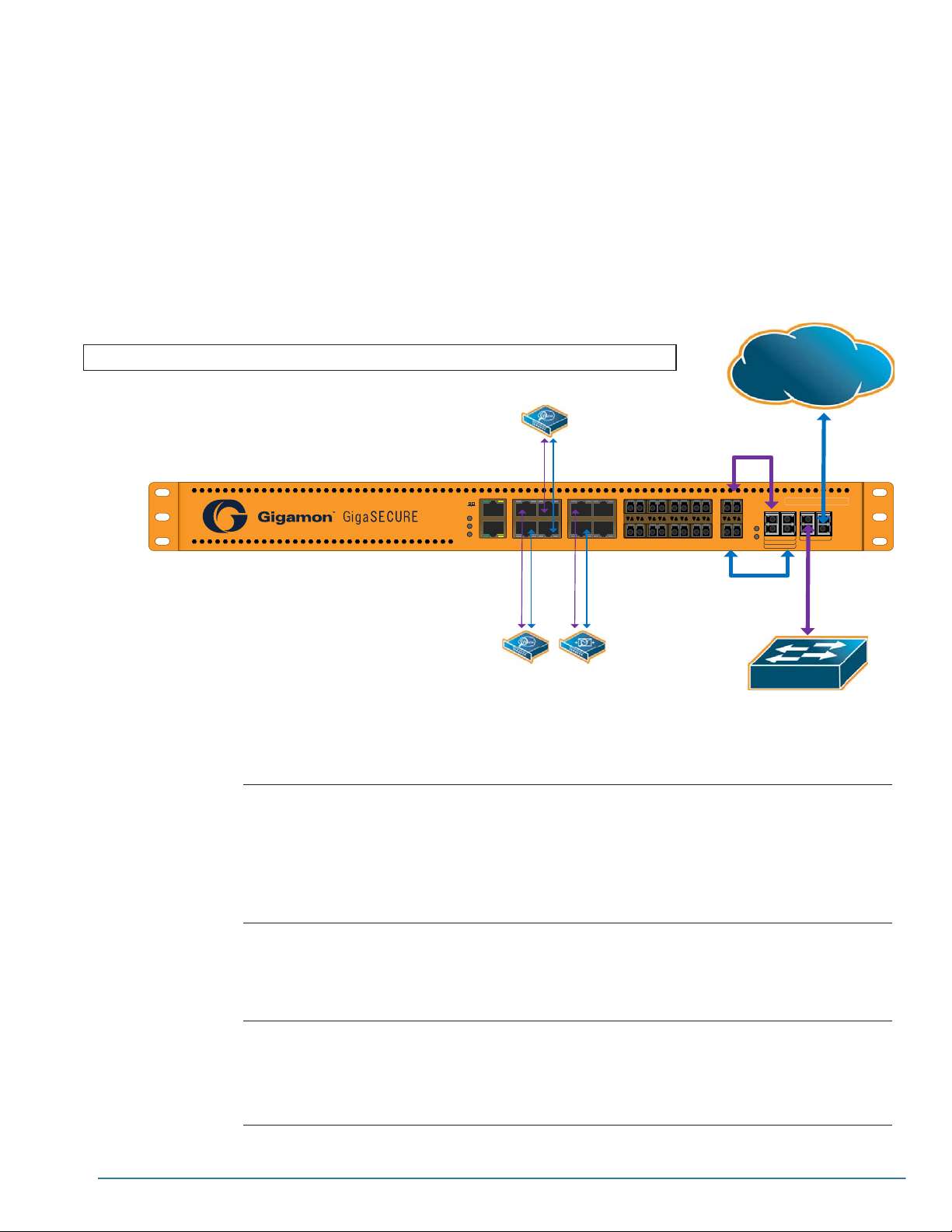
Planning the Distribution Model
Setting up an effective distribution model requires some planning – you can’t build the
distribution model with successive config distribution commands – each new config
distribution command overwrites the existing distribution completely. So, it’s a good
idea to build the config distribution command in a text editor, figuring out which
distribution-rules you want to include, eventually pasting the results into the CLI.
For example, suppose you want to send all HTTP traffic to separate 1G instances of an
inline web monitoring device on the g1 and g2 tool port pairs and all POP-based email
to an inline spam filtering device on g3 as shown in the figure below:
config distribution profile pp_HTTP_0 pp_HTTP_1 tool g1..g2 profile pp_HTTPS tool g1..g2 profile pp_POP_0 pp_POP_1 tool g3
WWW
Monitor
G5A
G5B
Console
G1A G2A
G1B G2B
TM
Mgmt
Status
Rdy
Pwr
G3A G4A
G3B G4B
10/100/1000PORTS 1GPORTS 10GPORTS
Internet
Fiber Jumper
Cable
G6A
G7A
G8A
X1A
Off= ByPass
G-SECURE-0216-MM
On= Inline
Mode
BPSPwr
AB
G6B
G7B
G8B
X2B
1G
10G
ToG8A To G8B
ToX1A ToX1B
AB
NETWORK
Fiber Jumper
Cable
WWW
Monitor
Email
Monitor
Switch
Here’s a plan with the necessary distribution-rules:
config distribution Sets up the distribution model
profile pp_HTTP_0 pp_HTTP_1 tool g1..g2 Sends all HTTP traffic on destination Port 80
(pp_HTTP_0) or 8080 (pp_HTTP_1) to the
load-balanced group of inline tools on g1..g2.
Note that this rule combines two profiles. Within a
single distribution-rule, the criteria are joined with a
logical OR – packets matching either criteria are sent
to the specified destination.
profile pp_HTTPS tool g1..g2 Sends all HTTPS traffic on destination Port 443 to the
load-balanced group of inline tools on g1..g2. This
traffic is encrypted, so presumably the monitoring tool
is equipped with certificates to decrypt and analyze
relevant portions of the traffic.
profile pp_POP_0 pp_POP_1 tool g3 Sends all POP traffic on destination Port 109
(pp_POP_0) or 1 10 (pp_POP_1) to the load-balanced
group of inline tools on g1..g2.
Similar to the first distribution rule, these profiles are
joined with a logical OR in a single rule.
Configuring GigaSECURE Packet Distribution 89
Page 90

Once you’ve planned the distribution model, you can paste the whole command into
the CLI. For example:
config distribution profile pp_HTTP_0 pp_HTTP_1 tool g1..g2 profile pp_HTTPS tool g1..g2 profile pp_POP_0 pp_POP_1 tool g3
About the Collector – Explicit and Implicit Collector Destinations
When configuring the set of distribution rules that control how packets arriving on the
Network A/B ports are distributed to inline tools, you need a way to handle packets that
do not match any configured rule. Enter the Collector.
The Collector is the “everything else” bucket – it’s where the GigaSECURE appliance
sends all packets not matching any other distribution rule. The Collector is configured
either implicitly or explicitly:
• Explicit Collector – Bind the predefined Collector profile (pp_Collector)asa
standalone distribution-rule sending unmatched traffic to a specific destination.
Regardless of where the Collector profile appears in the list of distribution-rules, it’s
always applied last, after all other rules have been checked for matches.
• Implicit Collector – Do not create a distribution-rule with the predefined Collector
profile. In this case, the Collector becomes the opposite network port – unmatched
traffic passes straight to the opposite side of the network without passing through
any of the connected inline tools.
Collector Example
Recall our distribution model example from Planning the Distribution Model on
page 89. Here you can see the distribution-rules issued in a single config distribution
command. We’ve used different colors for each distribution-rule so you can easily see
them in the command – each distribution-rule in the model starts with the profile
statement:
config distribution profile pp_HTTP_0 pp_HTTP_1 tool g1..g2 profile pp_HTTPS tool g1..g2 profile pp_POP_0 pp_POP_1 tool g3
Notice that we haven’t specified an explicit collector destination. This means that all
unmatched traffic will be sent straight to the opposite side of the network without
inspection by any of the connected tools. Suppose we wanted to send all traffic not
matching any currently configured distribution-rule to a load-balanced group of 1G
intrusion prevention tools connected to g5..g6. Let’s add that collector destination in
red here:
config distribution profile pp_HTTP_0 pp_HTTP_1 tool g1..g2 profile pp_HTTPS tool g1..g2 profile pp_POP_0 pp_POP_1 tool g3
profile pp_Collector tool g5..g6
90 CLI User’s Guide
Page 91
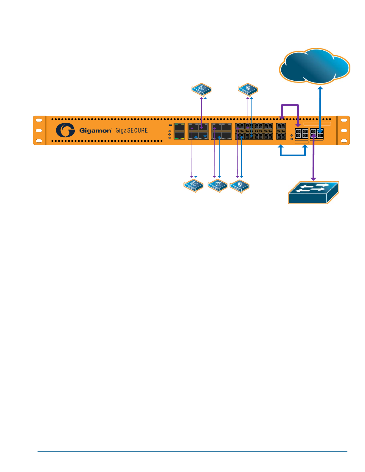
Here’s an illustration of our new configuration:
Distribution-Rule Priority
WWW
Internet
Monitor
Console
G1A G2A
G1B G2B
TM
Mgmt
Status
Rdy
Pwr
WWW
Monitor
G3A G4A
G3B G4B
10/100/1000PORTS 1GPORTS 10GPORTS
Email
Monitor
G5A
G5B
1G IPS
1G IPS
G6A
G6B
Fiber Jumper
Cable
G7A
G8A
X1A
Off= ByPass
G-SECURE-0216-MM
On= Inline
Mode
BPSPwr
AB
G7B
G8B
X2B
1G
10G
ToG8A ToG8B
ToX1A To X1B
AB
NETWORK
Fiber Jumper
Cable
Switch
The order of distribution-rules in the current distribution model does matter – keep in
mind that packets are sent to the first matching rule in the config distribution
command. It’s not uncommon for a packet to match multiple rules – keep in mind that
such packets will be sent to the destination specified by the first matching rule in the
list. That’s why it’s a good idea to keep a copy of your current config distribution
command in a text editor for occasional tweaking.
OTE: If you don’t save the config distribution command, you can always get it back
N
by uploading a command file to the console showing the running config with the
upload -cmd -running -console command. This will give you the exact config
distribution command necessary to recreate the current configuration.
About Load-Balanced Groups
The GigaSECURE appliance can send traffic to either an individual inline tool or a
load-balanced group of inline tools.
The GigaSECURE system distributes traffic between the ports in a load-balanced
group by hashing on the IP source and destination addresses.
Because traffic is hashed rather than divided evenly, the bandwidth available for a
load-balanced group is not a straight multiple of the number of 1G ports in the bundle –
some flows will use more bandwidth than others. However, it is a reasonable
approximation.
Configuring GigaSECURE Packet Distribution 91
Page 92

N
OTE: The GigaSECURE system tries to distribute traffic evenly across all constituent
inline tool ports. However, live network traffic is often unpredictable, including bursty
periods for certain source/destination flows. Because of this, the distribution patterns
described below are not ironclad – variations in traffic will result in variations in
distribution.
Traffic Distribution Details
Load-balanced groups divide the packets across the constituent tool ports in the same
order in which they were added in the CLI command:
• When a load-balanced group consists of 2, 4, or 8 ports, packets are distributed
evenly across the ports.
When a load-balanced group consists of 3, 5, 6, or 7 ports, packets are distributed
across the ports according to the proportions summarized in the table below:
Table 7-1: Traffic Distribution by Number of Ports in Load-Balanced Group
Number of Tool Ports Traffic Distribution
Port 1-3
(3 Ports Total)
Ports 1-5
(5 Ports Total)
Ports 1-6
(6 Ports Total)
Ports 1-7
(7 Ports Total)
Port 1 = 37.5%
Port 2 = 37.5%
Port 3 = 25%
Port 1 = 25%
Port 2 = 25%
Port 3 = 25%
Port 4= 12.5%
Port 5= 12.5%
Port 1 = 25%
Port 2 = 25%
Port 3 = 12.5%
Port 4 = 12.5%
Port 5 = 12.5%
Port 6 = 12.5%
Port 1 = 25%
Port 2 = 12.5%
Port 3 = 12.5%
Port 4 = 12.5%
Port 5 = 12.5%
Port 6 = 12.5%
Port 7 = 12.5%
Viewing the Active Distribution Model
Once you’ve created a new distribution model, it’s a good idea to review it with the
show distribution, show connect, and show failover commands.
show distribution
The show distribution command displays the distribution rules in place on the
system, including both the state of the physical and logical bypasses, as well as the
92 CLI User’s Guide
Page 93

distribution rules in place on the system. Here’s an example of the show distribution
output for our current example:
new_gsecure>show distribution
******************************************************************
* Distribution *
******************************************************************
Bypass
==================================================================
Physical : Off
Logical : Conditional
==================================================================
Distribution Map
==================================================================
Network A : x1a
Total Profile Count: 6
------------------------------------------------------------Profile:pp_HTTP_0 Ports: g1a..g2a
=====================
IP Dst Port #: 80
------------------------------------------------------------Profile:pp_HTTP_1 Ports: g1a..g2a
=====================
IP Dst Port #: 8080
------------------------------------------------------------Profile:pp_HTTPS Ports: g1a..g2a
=====================
IP Dst Port #: 443
------------------------------------------------------------Profile:pp_POP_0 Port: (g3a)
=====================
IP Dst Port #: 109
------------------------------------------------------------Profile:pp_POP_1 Port: (g3a)
=====================
IP Dst Port #: 110
------------------------------------------------------------Profile:pp_Collector Ports: g5a..g6a
=====================
Collector: All unmatched packets
------------------------------------------------------------===================================================================
Network B : x1b
Total Profile Count: 6
------------------------------------------------------------Profile:pp_HTTP_0 Ports: g1b..g2b
=====================
IP Dst Port #: 80
------------------------------------------------------------Profile:pp_HTTP_1 Ports: g1b..g2b
=====================
IP Dst Port #: 8080
------------------------------------------------------------Profile:pp_HTTPS Ports: g1b..g2b
=====================
IP Dst Port #: 443
------------------------------------------------------------Profile:pp_POP_0 Port: (g3b)
=====================
IP Dst Port #: 109
------------------------------------------------------------Profile:pp_POP_1 Port: (g3b)
=====================
IP Dst Port #: 110
------------------------------------------------------------Profile:pp_Collector Ports: g5b..g6b
=====================
Collector: All unmatched packets
------------------------------------------------------------===================================================================
Configuring GigaSECURE Packet Distribution 93
Page 94

show connect
The show connect command lets you see the flows from tool ports back to the
network, well as all load-balanced groups and the distribution model in place. Here’s an
example of the show connect output for our current example:
The Ports Connectivity
section shows the connections
from the tool ports back to the
network, with the “a” side ports
flowing back to the x1a port
and the “b” side tool ports
flowing to the x1b port.
Electrical ports are listed in
parentheses; optical ports,
without. In addition, you can
see that g4, g7, and g8 are not
used in this distribution model.
Here, you can see each of the
load-balanced groups of tool ports
created by our current distribution
model. Separate groups are
created for the a and b ports. You
can also see the collector
destination of g5b/g6b (all traffic
destined for the protected , or “b”
side of the network).
Finally, the Distribution Flow
portion of the show connect
output summarizes the inline tools
ports to which traffic arriving on
each ingress port is sent.
new_gsecure>show connect
***************************************************************************************
* Ports Connectivity *
***************************************************************************************
Network Port Tool Port
=================================== ===================================
x1a <-------------- ( g1a )
------ ------ x1b <-------------- ( g1b )
------ ------ x1a <-------------- ( g2a )
------ ------ x1b <-------------- ( g2b )
------ ------ x1a <-------------- ( g3a )
------ ------ x1b <-------------- ( g3b )
------ ------ x1a <-------------- g5a
------ ------ x1b <-------------- g5b
------ ------ x1a <-------------- g6a
------ ------ x1b <-------------- g6b
------ -------
( g4a )
( g4b )
g7a
g7b
g8a
g8b
Defined Inline Tool Groups
---------------------------------------------- Member Ports
1 ===>>> ----> (g1a )
----> (g2a )
2 ===>>> ----> (g1b )
----> (g2b )
3 ===>>> ----> g5a
----> g6a
4 ===>>> ----> g5b
----> g6b
----------------------------------------------***************************************************************************************
* Distribution Flow *
***************************************************************************************
Network A
============================================
----> g1a..g2a
x1a ===>>> ----> (g3a )
----> g5a..g6a
-- ---------------------------- --
Network B
============================================
----> g1b..g2b
x1b ===>>> ----> (g3b )
----> g5b..g6b
-- ---------------------------- --
94 CLI User’s Guide
Page 95

show failover
The show failover command lets you see the failover settings in place for each inline
tool port pair on the G-SECURE-0216. Here we’ve limited the display to ports g1..g3.
Each port is shown with a summary of its configuration
settings. Ports g1..g2 are part of a load-balanced group, as
you can see in the Part of Inline group entry.
We’ve enabled the heartbeat feature on this group using
config failover tool g1..g2 hb_protocol enabled, accepting
the default settings for each of the optional attributes.
Because we’ve accepted defaults, the heartbeat packet is
sent in both directions, the minimum group size is set to the
number of ports in the group (meaning that if any port in the
group fails, the entire group fails over to the Bypass option),
and the various timers are all at their defaults. You can also
see counts for the heartbeat packets sent in both directions.
See Configuring Heartbeat/Failover on page 96 for more
information on available failover settings.
new_gsecure>show failover tool g1..g3
==================================================================
Network Ports : x1a x1b
==================================================================
Inline Tool Port : g1
Part of Inline group : g1 g2
Current Failed Ports : none
Minimum Group : 2
Rebalancing : Enabled
Action on failover : Bypass
Current State : Forwarding
Heartbeat Protocol : Enabled
Heartbeat Direction : Both
Heartbeat Period : 1000 (msec)
Heartbeat Timeout : 500 (msec)
Heartbeat Retries : 3
Fail Recovery Period : 30 (sec)
Custom Heartbeat Packet : Disabled
Custom Heartbeat Pkt Filename :
Tool IP Address : 1.1.1.1
Heartbeat Stats (AtoB) : TX: 74341 RX:74341
Heartbeat Stats (BtoA) : TX: 74341 RX:74341
-----------------------------------------------------------------Inline Tool Port : g2
Part of Inline group : g1 g2
Current Failed Ports : none
Minimum Group : 2
Rebalancing : Enabled
Action on failover : Bypass
Current State : Forwarding
Heartbeat Protocol : Enabled
Heartbeat Direction : Both
Heartbeat Period : 1000 (msec)
Heartbeat Timeout : 500 (msec)
Heartbeat Retries : 3
Fail Recovery Period : 30 (sec)
Custom Heartbeat Packet : Disabled
Custom Heartbeat Pkt Filename :
Tool IP Address : 2.2.2.2
Heartbeat Stats (AtoB) : TX: 74673 RX:74672
Heartbeat Stats (BtoA) : TX: 74673 RX:74672
-----------------------------------------------------------------Inline Tool Port : g3
Action on failover : Bypass
Current State : Forwarding
Heartbeat Protocol : Enabled
Heartbeat Direction : Both
Heartbeat Period : 1000 (msec)
Heartbeat Timeout : 500 (msec)
Heartbeat Retries : 3
Fail Recovery Period : 30 (sec)
Custom Heartbeat Packet : Disabled
Custom Heartbeat Pkt Filename :
Tool IP Address : 3.3.3.3
Heartbeat Stats (AtoB) : TX: 74336 RX:74336
Heartbeat Stats (BtoA) : TX: 74336 RX:74336
------------------------------------------------------------------
Figure 7-3: Configuring Failover/Heartbeat Settings
Profile and Distribution Maximums
Keep in mind the foll
Configuring GigaSECURE Packet Distribution 95
Page 96

Configuring Heartbeat/Failover
The GigaSECURE appliance provides failover protection for inline tool port pairs and
load-balanced groups, allowing you to specify how failure conditions are handled.
You can configure failover detection differently for individual ports and load-balanced
groups. In addition, when configuring failover for load-balanced groups, you can
configure how traffic is handled when one tool in a group of load-balanced tools fails,
either failing over to the next configured port or rebalancing over all ports in the group.
See the following sections for details:
• GigaSECURE Failover Methods
• Syntax for config failover
• Using Link Status Propagation
• About Heartbeat Packet Usage
GigaSECURE Failover Methods
The table below summarizes the types of failover protection available for the
GigaSECURE appliance.
Failover
Condition
Link Down
Failure
Heartbeat
Packet Failure
Description Failover Type Link Status Propagation
If the link status of either of the inline
tool ports in a gxa/gxb pair goes
down, the GigaSECURE appliance
declares the tool failed and performs
the type of logical failover configured
for the port.
You can configure the GigaSECURE
appliance to send a regular heartbeat
packet through a gxa/gxb tool port
pair. The GigaSECURE performs a
logical failover using one of the
methods at right if a specified number
of heartbeat packets are not seen
returning from the inline tool within a
specified time. Refer to About
Heartbeat Packet Usage on page 101
for details on configuring the
Heartbeat Packet feature.
Logical
You can configure logical failover to
use either of the following methods
with the config failover command’s
action <bypass|drop> argument:
• bypass – Traffic is not sent to the
connected inline tool, but is instead
routed out the opposite port in the
gxA/gxB pair and back to the
network.
• drop – Traffic destined for the down
tool is dropped. This setting is
appropriate for high-security
installations where no packet is
allowed in or out of the networ k
without inspection.
If network-port-force-down is
enabled, the network ports can be
forced down upon detection of a
failure condition on a tool port or
tool port group, alerting upstream/
downstream equipment to fail
over to an alternate security path.
96 CLI User’s Guide
Page 97

Failover
Condition
Power Failure
Description Failover Type Link Status Propagation
Using the GigaSECURE Node with
the Optical Protection Switch
The GigaSECURE system’s optical
protection switch automatically
couples the fibers between the
Network A/B ports during a power
failure condition, protecting the link.
Using the GigaSECURE Node
without the Optical Protection
Switch
Some high-security sites may have
policies requiring that no packet enter
the network without inspection by
specific inline security tools. In cases
such as this, you can deploy the
GigaSECURE node without the
optical protection switch – in the event
of a power failure, packets will not be
able to pass in or out of the network.
Syntax for config failover
Physical
Physical failover takes place
automatically when using the optical
protection switch.
No Failover Automatic
N/A
In the event of a power failure,
packets will not be able to pass in
or out of the network.
You configure GigaSECURE failover with the config failover command. The syntax is
as follows:
config failover
tool <port|port_list|all>
[action <bypass|drop>]
[rebalancing <disabled|enabled>]
[min_group <1~8>]
[hb_custom_pkt <disabled|enabled>]
[hb_direction <AtoB|BtoA|both>]
[hb_period <msec (500~5000)>]
[hb_protocol <disabled|enabled>]
[hb_recovery_period <sec (5~60)>]
[hb_retries <0~5>]
[hb_timeout <msec (100~1000)>]
[hb_tool_ipaddr <addr>]
network-port-force-down <on|off>
Table 7-2 describes each of the config failover arguments:
Table 7-2: Arguments for config failover
Argument Description
tool <port|port_list|all> Specifies the port number(s) to which the failover settings configured here apply. You can
specify either a single port, a group of ports (port_list), or all ports.
If you specify a port_list, it must either exactly match an existing port_list already
created with the config distribution command’s tool argument or not include any ports
in a load-balanced group at all. The config failover command doesn’t create a load
balanced group by itself.
Configuring GigaSECURE Packet Distribution 97
Page 98

Table 7-2: Arguments for config failover
Argument Description
[action <bypass|drop>] Specifies the type of logical failover to perform when the port or group is declared failed:
• bypass – Traffic is not sent to the connected inline tool, but is instead routed out the
opposite port in the gxa/gxb pair and back to the network.
• drop – Traffic destined for the down tool is dropped. This setting is appropriate for
high-security installations where no packet is allowed in or out of the network without
inspection.
NOTE: A load-balanced group is declared failed when the number of active ports falls
below the min_group setting, configured below.
[rebalancing <disabled|enabled>] Specifies how a load-balanced group handles the failure of a member port:
rebalancing = disabled (Default)
When rebalancing is disabled, packets on the failed port are sent to the next
consecutive port in the load-balanced group. If the failed port is the last port added to the
group, traffic is sent to the first configured port.
• The advantage of this approach is that it preserves the set of source/destination IP/
port flows being sent over the failed port.
• The disadvantage of this approach is that fail over to a single tool port can cause
oversubscription depending on the aggregate traffic now being sent to the next port in
the load-balanced group.
rebalancing = enabled
When rebalancing is enabled, packets on the failed port are redistributed over the
remaining ports in the load-balanced group with a good link.
For example, consider a load-balanced group set up on Ports g1..g4. If Port g3 goes
down, the aggregate traffic that was being sent over g1..g4 is rehashed across g1, g2,
and g4 based on IP source and destination addresses (see About Load-Balanced
Groups for more information).
Note: You can’t enable the rebalancing option for a group when one or more of its ports
is in a failed state. The system will warn you if you try to do so.
[min_group <1~8>] Specifies the minimum number of active ports required to sustain the load-balanced
group. If the number of active ports in the group falls below this minimum, the
GigaSECURE appliance declares the group failed and performs the logical failover
action specified above (either routing traffic to the opposite inline network port or
dropping all traffic).
[hb_custom_pkt
<disabled|enabled>]
Specifies which packet to use as a heartbeat packet. If you find that an Intrusion
Protection System connected to an inline tool port pair on the GigaSECURE appliance is
not passing the default ARP packet used for the heartbeat packet, you can upload a
custom packet in a standard PCAP file. The packet in the PCAP file must be between
60-200 bytes not including the CRC.
• disabled – Default 64-byte ARP packet is used as heartbeat, optionally including the
destination address specified by Tool IP Address, if defined.
• enabled – Packet in .pcap file uploaded to the GigaSECURE appliance is used as
heartbeat. Click the adjacent TFTP Install link to install the .pcap file. The
GigaSECURE appliance will prompt you for the name of the PCAP file and the IP
address of the TFTP server where the file is stored.
NOTE: Separate PCAP files must be uploaded for each port using a custom heartbeat
packet.
NOTE: This argument is only used when the heartbeat feature is actually enabled with
the hb_protocol enabled argument.
98 CLI User’s Guide
Page 99

Table 7-2: Arguments for config failover
Argument Description
[hb_direction <AtoB|BtoA|both>]
Specifies which direction the heartbeat packet should be sent:
• AtoB – Heartbeat is sent out gxa
• BtoA – Heartbeat is sent out gxb
• Both – Heartbeat packets are sent out both gxa and gxb. This is the default setting.
[hb_period <msec (500~5000)>]
[hb_protocol <disabled|enabled>] Specifies whether to use heartbeat failover detection for the selected port(s). When the
[hb_recovery_period <sec (5~60)>]
[hb_retries <0~5>]
[hb_timeout <msec (100~1000)>]
[hb_tool_ipaddr <addr>]
Specifies the interval between heartbeat packets transmitted by the GigaSECURE
system.
Default – 1000 milliseconds (one second)
heartbeat packet is enabled, the GigaSECURE system sends a packet through the
specified inline tool ports and monitors how long it takes for the packet to return to the
system, timing it out after a specified amount of time (hb_timeout).
If you enable hb_protocol here, you use the other arguments described in this table to
configure its settings on a per-port basis.
Specifies the number of consecutive seconds with successfully received hear tbeat
packets at which the GigaSECURE system will restore traffic flow through the inline tool
ports.
Default – 30 seconds
Specifies the number of consecutive timed-out heartbeat packets at which the
GigaSECURE appliance will trigger a failover condition and perform the logical failover
Action configured for the port.
Default – 3 retries
Specifies how long the GigaSECURE appliance waits for the return of the heartbeat
packet from the connected inline tool before declaring it timed out.
Default – 500 milliseconds
By default, the heartbeat packet is a 64-byte ARP packet. You can use this option to
include the IP address of the connected inline tool in the ARP packet. If you do not
include an IP address, a dummy destination address of <port.port.port.port> is used,
where the port is the number of the gx port from which the packet is sent.
By design, Intrusion Protection Systems are selective about which packets to pass.
Heartbeat packets must be passed through the tool connected to the inline tool ports for
successful usage. Supplying the IP address of the connected inline tool in the ARP
packet is one way to ensure that the heartbeat packet is passed successfully. The other
way is to upload a custom packet in a .pcap file and enable Custom Heartbeat Packet,
as described above.
NOTE: If Custom Heartbeat Packet is enabled, the tool_ipaddr option is ignored and
the packet supplied in the custom .pcap file is used instead.
network-port-force-down <on|off>
Specifies whether to force down the network ports if failure on any tool port or tool port
group is detected. This is a global option – it applies to all tool ports and tool port groups.
By default, network-port-force-down is disabled. Refer to Using Link Status
Propagation on page 100 for more information on link status propagation features.
NOTE: This option applies to the network ports in use and not the optical bypass switch.
To take advantage of this feature, deploy the G-SECURE--0216 with direct connections to
the network ports rather than the optical bypass switch; refer to Connecting the
GigaSECURE Node to the Production Network on page 62 for deployment diagrams.
Configuring GigaSECURE Packet Distribution 99
Page 100

Using Link Status Propagation
The G-SECURE-0216 inline traffic distribution node supports link status propagation
on its network ports. Link status propagation notifies upstream and downstream
switches and firewalls of a problem on the opposite side of the G-SECURE-0216 node,
allowing them to fail over to a secondary security path.
The G-SECURE-0216 can force the link on the input network ports down in the
following situations:
• Link status failure on one of the network ports
• Link status failure on one of the connected tool port pairs
N
OTE: Link status propagation is only available on the input network ports – x1a/x1b
(10G), g8a/g8b (1G optical), or g1a/g1b (1G copper). It is not available on the optical
protection switch ports. Only use link status propagation in deployments where the
input network ports are directly connected to the network and not connected via jumper
cables to the optical protection switch.
Use the following commands to configure link status propagation features:
Table 7-3: Arguments for config failover
Argument Description
config failover network-port-force-down <on|off>
You use this command to specify whether the input network ports should
be forced down if any tool por t or tool port group fails. By default, this
option is disabled.
config network-port-link-propagation <on|off>
Reviewing Link Status Propagation Settings and Status
Use the following show commands to review link status propagation settings:
• The show failover command reports the network ports in use, whether
network-port-force-down is enabled for the network ports upon failure of a tool
port or tool port group, and the current force-down state. For example:
==================================================================
Network Ports : g8a g8b ( optical )
Network-Port-Force-Down : Off
Ports Force-Down State : Not Forced Down
==================================================================
• The show distribution command reports the network ports in use, whether
network-port-link-propagation is enabled, and the current force-down state for
the network ports. For example:
G-SECURE>show distribution
******************************************************************
* Distribution *
******************************************************************
Bypass
==================================================================
Physical : On
Logical : On
You use this command to specify whether one network port should be
forced down if the other fails. By default, this option is disabled.
100 CLI User’s Guide
 Loading...