How it Works
Log In / Sign Up
Buy Points
How it Works
FAQ
Contact Us
Questions and Suggestions
Users
GIGABYTE
Loading...
Z
Z370 AORUS GAMING 5
Z370 Aorus Gaming K3
Z370 AORUS Ultra Gaming
Z370 Aorus Ultra Gaming WIFI
Z370 Aorus Ultra Gaming WIFI-OP
Z370 HD3
3
Z370 HD3P
Z370M AORUS Gaming
Z370M D3H
Z370M DS3H
Z370P D3
Z390
2
Z390 Aorus elite
Z390 Aorus Pro
Z390 Aorus Ultra
Z390 Aorus Xtreme
Z390 AORUS XTREME WATERFORCE
2
Z390 AORUS XTREME WATERFORCE 5G
Z390 D
Z390 Designare
Z390 Gaming SLI
Z390 Gaming X
Z390 I Aorus Pro WIFI
Z390 M
Z390 M Gaming
Z390 UD
Z490
Z490 Aorus elite
Z490 Aorus Master
Z490 AORUS MASTER WATERFORCE
Z490 AORUS MASTER WF
Z490 Aorus Pro AX
2
Z490 Aorus Ultra
Z490 Aorus Xtreme
Z490 Aorus Xtreme Waterforce
Z490 AORUS XTREME WF
Z490 Gaming X
Z490 Gaming X AX
Z490I Aorus Ultra
Z490M
Z490M Gaming X
Z490 UD
Z490 Vision D
Z490 VISION G
Z590
Z590 AORUS ELITE
2
Z590 AORUS ELITE AX
2
Z590 AORUS MASTER
Z590 AORUS TACHYON
Z590 AORUS ULTRA
Z590 AORUS XTREME
Z590 AORUS XTREME WATERFORCE
Z590 AORUS XTREME WB
2
Z590 D
2
Z590 GAMING X
2
Z590 GAMING X AX
2
Z590I AORUS ULTRA
Z590I VISION D
3
Z590M
2
Z590M GAMING X
4
Z590 UD
Z590 UD AC
Z590 VISION D
2
Z590 VISION G
2
Z690 A ELITE AX DDR4
Z690 AORUS ELITE
Z690 AORUS ELITE AX
Z690 AORUS ELITE AX DDR4
Z690 AORUS ELITE DDR4
Z790 A ELITE AX DDR4
Z790 A ELITE DDR4
Z790 AORUS ELITE
Z790 AORUS ELITE AX
Z790 AORUS ELITE AX DDR4
Z790 AORUS ELITE DDR4
Loading...
Loading...
Nothing found
Z590 AORUS XTREME
Users guide
108 pgs
35.36 Mb
0
Table of contents
Loading...
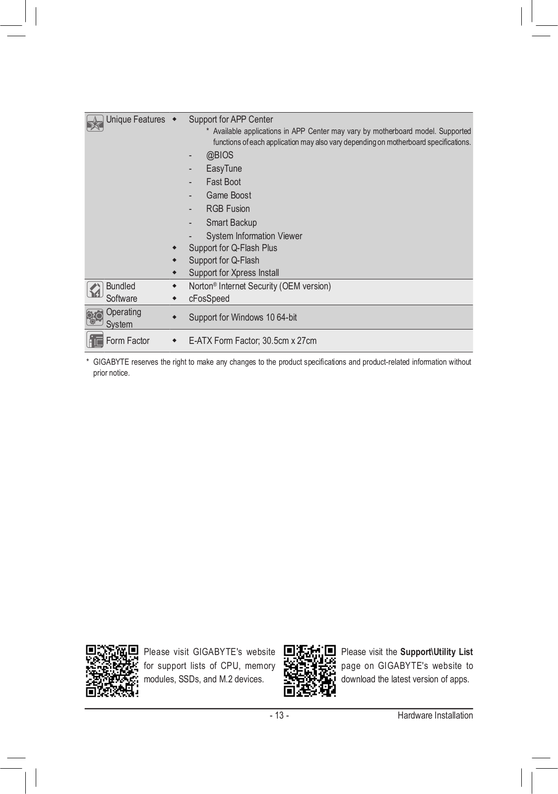
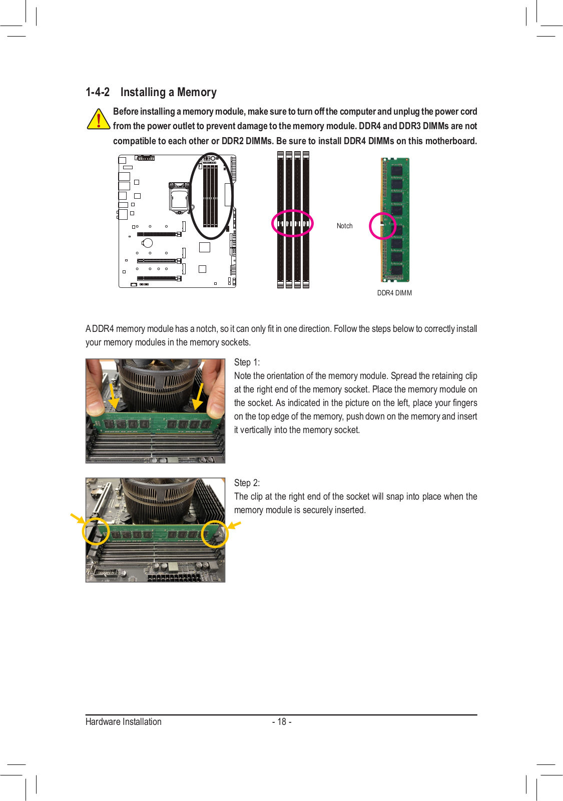
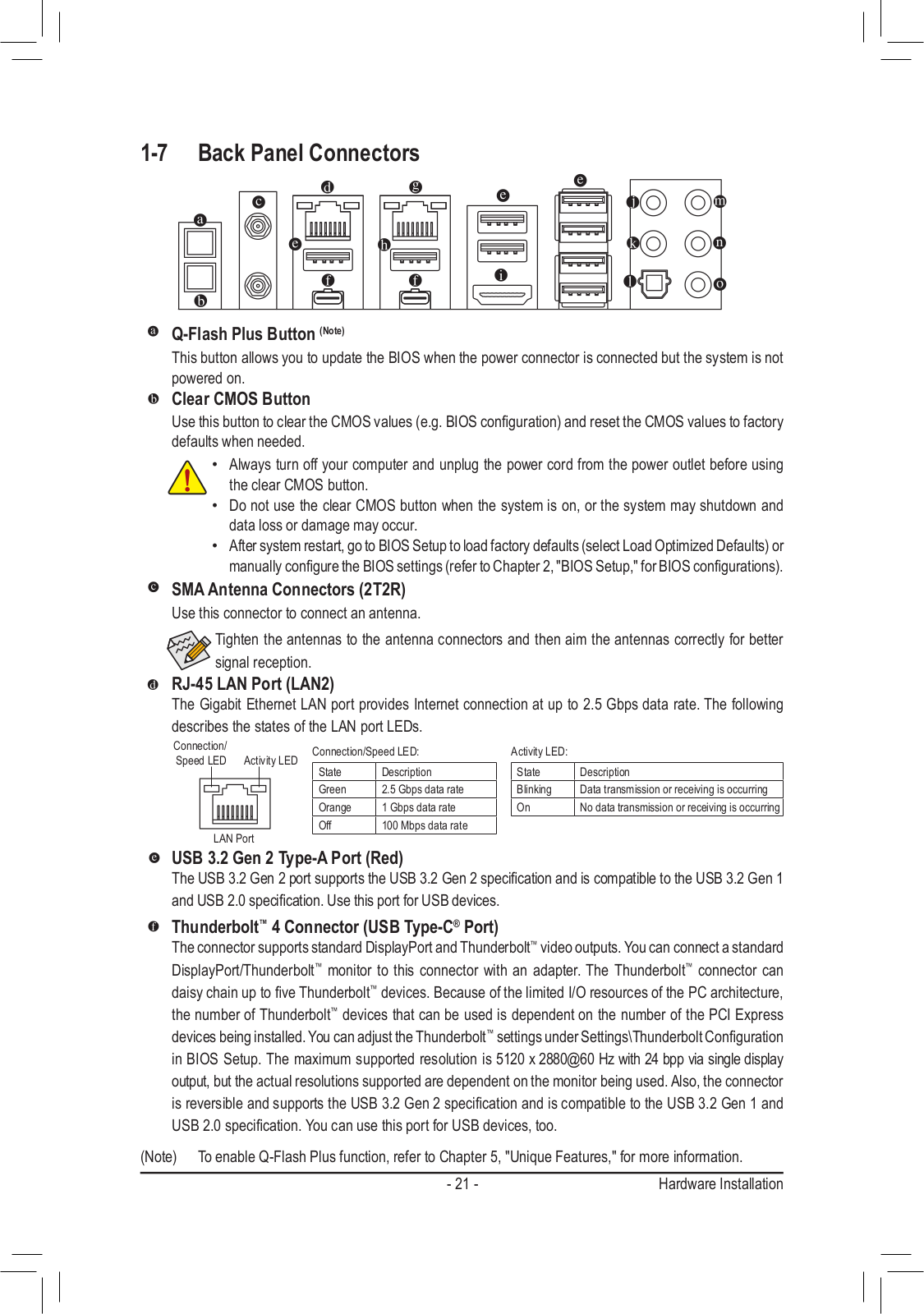
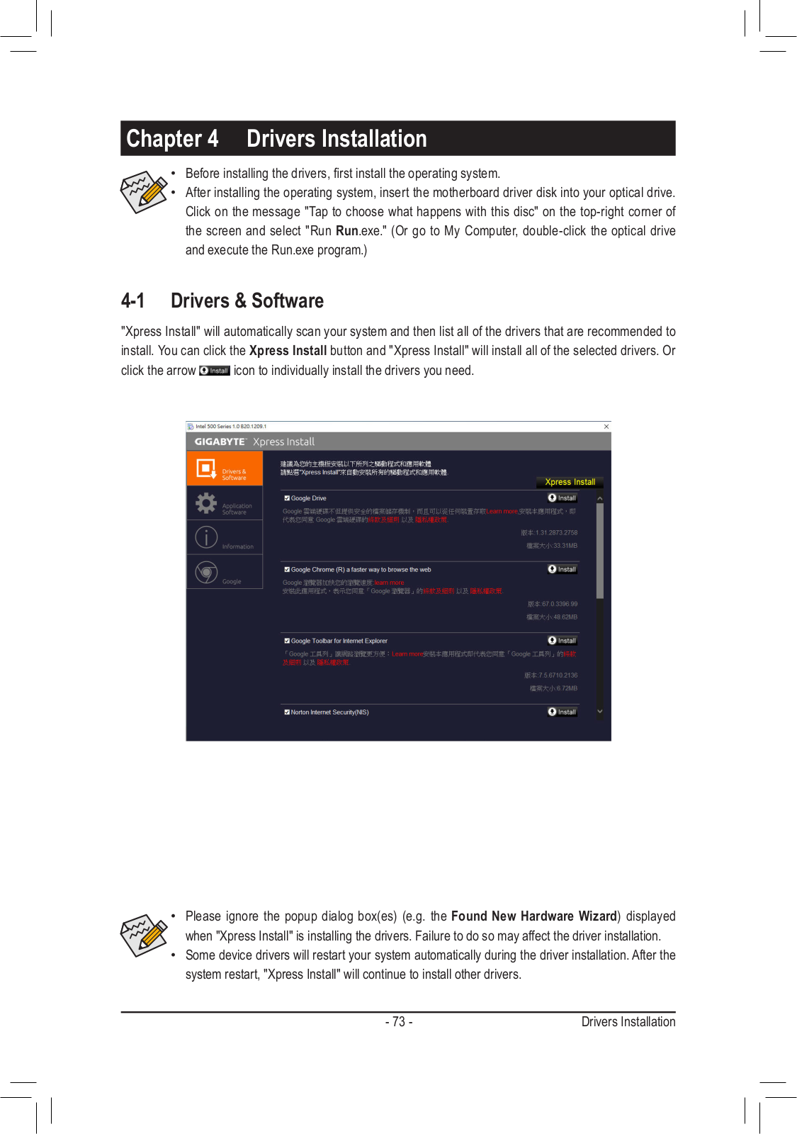
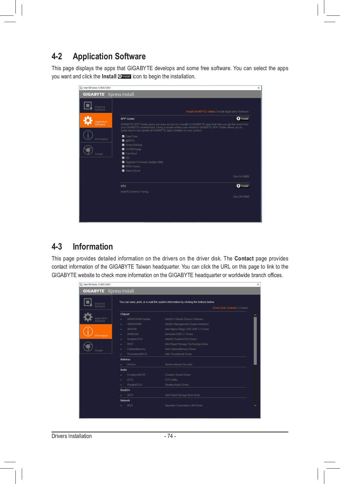
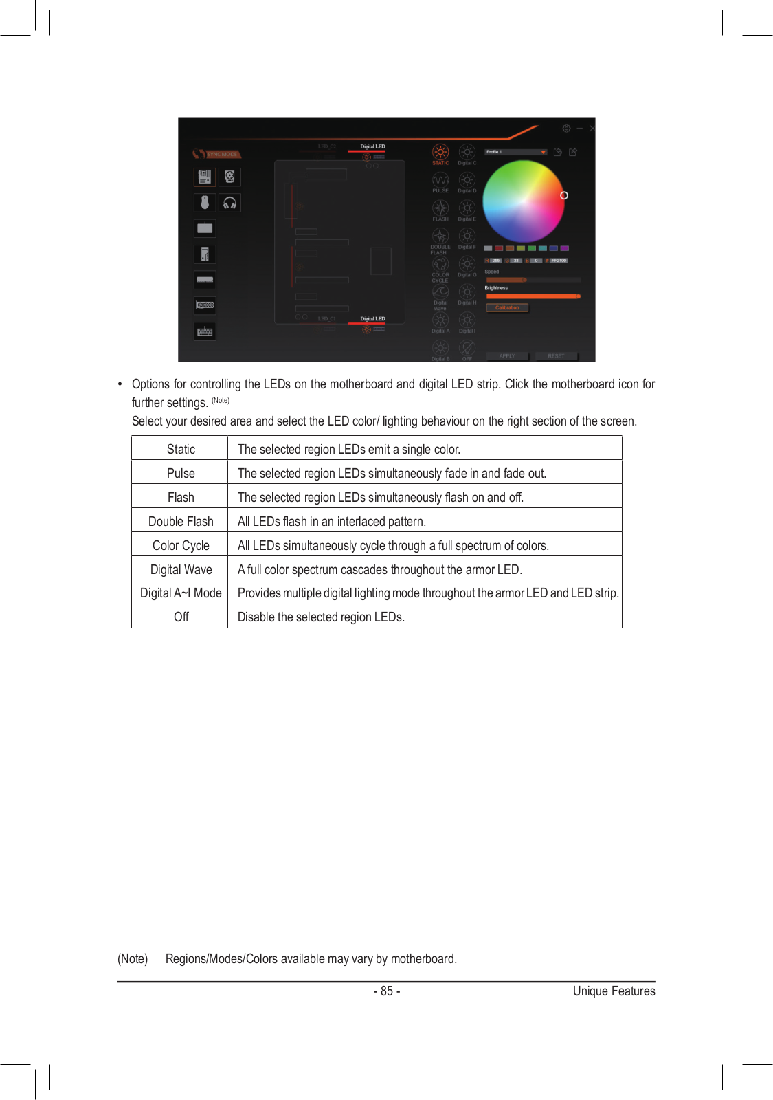
GIGABYTE Z590 AORUS XTREME Users guide
...
GIGABYTE Users guide
Download
Specifications and Main Features
Frequently Asked Questions
User Manual
Download
Loading...
+
hidden pages
Unhide
You need points to download manuals.
1 point = 1 manual.
You can buy points or you can get point for every manual you upload.
Buy points
Upload your manuals
 Loading...