

Page 1
Page 2

Page 3

About this User’s Manual
This user’s manual is designed to let you easily find the information you need to
get the most from your notebook.
• Introduces you to the features of your notebook.
• Gives you useful details on using your notebook.
• Tells you how to look after your notebook, whether at home or traveling.
• Talks about PCI Express Card peripherals and how to use them.
• Goes into more detail about power management and explains how to
conserve power while on the move.
• Introduces you to BIOS, the nervous system of your computer, and how to
change its fundamental settings.
There is no need to read the manual from the beginning to end. Simply find your
way to the section that interests you using the table of contents, or browse
through the manual.
You will come across the following icons in this manual:
Helpful pointers and tricks to get more from your notebook
To help you note and avoid possible damage to your notebook's hardware
or software, or loss of your work
Points out possible damage to property, personal injury or death
Information in this document is subject to change without notice.
© GIGA-BYTE TECHNOLOGY CO., LTD.. 2007. All rights reserved.
Trademarks used in this document: Microsoft and Windows are registered
trademarks of Microsoft Corporation.
Other trademarks and trade names may be used in this document to refer to
either the entities claiming the marks and names or their products.
Page 4

Page 5

Contents
Safety Instructions................................................................... i
Modem Regulatory Notice...................................................... ii
Specifications........................................................................ vii
Chapter 1 Introducing Your Notebook
1.1 Front Side ........................................................................................... 1-1
1.1.1 Internal Speakers ............................................................................ 1-2
1.1.2 Built-in Microphone.......................................................................... 1-2
1.1.3 Display............................................................................................. 1-2
1.1.4 Top Panel Buttons and LEDs........................................................... 1-3
1.1.5 Left Panel Buttons ........................................................................... 1-4
1.1.6 Keyboard ......................................................................................... 1-4
1.1.7 Touch Pad ....................................................................................... 1-6
1.1.8 Touch Pad Buttons .......................................................................... 1-7
1.1.9 Wireless Communication Switch ..................................................... 1-8
1.1.10 Device Status Indicators / Power Status.......................................... 1-8
1.2 Right Side ........................................................................................... 1-9
1.2.1 Optical Media Drive ....................................................................... 1-10
1.2.2 USB Port ....................................................................................... 1-10
1.2.3 AC Adapter Connector................................................................... 1-10
1.3 Left Side ............................................................................................ 1-11
1.3.1 VGA Port ....................................................................................... 1-12
1.3.2 LAN Jack ....................................................................................... 1-12
1.3.3 Modem Jack .................................................................................. 1-12
1.3.4 S-Video out Port ............................................................................ 1-12
1.3.5 High Power USB Port .................................................................... 1-12
1.3.6 IEEE 1394 Port.............................................................................. 1-12
1.3.7 New Card Slot (For Express Card)................................................ 1-13
1.3.8 Multiple Digital Media Card Slot..................................................... 1-14
1.3.9 Audio Ports.................................................................................... 1-14
1.4 Rear Side........................................................................................... 1-15
1.5 Bottom Side ......................................................................................1-16
1.5.1 Battery Pack .................................................................................. 1-17
1.5.2 Battery Release Latch ................................................................... 1-17
1.5.3 Memory Modules........................................................................... 1-18
Page 6

Chapter 2 Operating Your Notebook (Vista)
2.1 Networks ............................................................................................. 2-1
2.2 Playing CDs and Movies.................................................................... 2-2
2.2.1 Inserting Discs................................................................................. 2-2
2.2.2 Adjusting the Volume....................................................................... 2-2
2.2.3 Adjusting the Picture........................................................................ 2-2
2.3 Power Management ........................................................................... 2-4
2.3.1 Managing Your Notebook’s Power................................................... 2-4
2.3.2 Power Management Modes............................................................. 2-4
2.3.3 Power Options Properties................................................................ 2-5
2.3.4 SpeedStep ....................................................................................... 2-6
2.4 Battery................................................................................................. 2-8
2.4.1 Battery Performance........................................................................ 2-8
2.4.2 Checking the Battery Charge .......................................................... 2-8
2.4.3 Power Meter .................................................................................... 2-8
2.4.4 Low-Battery Warning ....................................................................... 2-9
2.4.5 Charging the Battery........................................................................ 2-9
2.4.6 Removing the Battery ...................................................................... 2-9
2.4.7 Installing a Battery......................................................................... 2-10
2.4.8 Storing a Battery............................................................................ 2-10
2.4.9 Working With Extra Battery Packs................................................. 2-10
2.4.10 Maximizing Battery Life ................................................................. 2-10
2.5
Advanced Charging Functions: Q-Charging & Power USB Buttons
.......
2-11
2.5.1 Q-Charging Button with Smart Battery Software ........................... 2-11
2.5.2 Using the Q-Charging Button ........................................................ 2-12
2.5.3 Using the Power USB Button ........................................................ 2-12
2.6 WOW Video & Audio ........................................................................ 2-13
2.6.1 Installing the Software ................................................................... 2-13
2.6.2 Using the Software ........................................................................ 2-13
2.6.3 Changing Software Settings .......................................................... 2-13
Chapter 3 Caring for Your Notebook
3.1 Caring for Your Notebook.................................................................. 3-1
3.1.1 Cleaning Your Notebook and Keyboard........................................... 3-1
3.1.2 Cleaning the Display........................................................................ 3-1
3.1.3 Cleaning the Touch Pad .................................................................. 3-1
3.1.4 Cleaning the CD/DVD Drive ............................................................ 3-1
3.1.5 Precautions ..................................................................................... 3-2
3.2 Traveling .............................................................................................3-3
3.2.1 Identifying Your Notebook................................................................ 3-3
Page 7

3.2.2 Packing Your Notebook ................................................................... 3-3
3.2.3 Setting a Password.......................................................................... 3-3
3.2.4 Travel Tips .......................................................................................3-4
3.2.5 If Your Notebook is Lost or Stolen ................................................... 3-4
Chapter 4 Operating Your Notebook (Vista)
4.1 Introduction ........................................................................................4-1
4.2 Navigating through the BIOS Setup Program.................................. 4-2
4.2.1 Accessing the BIOS Setup Program................................................ 4-3
4.2.2 Launching Submenus...................................................................... 4-4
4.2.3 Saving Changes and Exiting the Setup Program ............................ 4-4
4.3 The Main Menu ...................................................................................4-5
4.4 The Advanced Menu .......................................................................... 4-7
4.5 The Security Menu ............................................................................. 4-8
4.6 The Boot Menu ................................................................................. 4-12
4.7 The Exit Menu................................................................................... 4-13
Chapter 5 Troubleshooting
5.1 Frequently Asked Questions............................................................. 5-1
Appendix A Recovery Update Notices
Appendix B Service Center
Page 8

Safety Instructions
i
Safety Instructions
Use the following safety guidelines to help protect yourself and your computer.
General Warnings
• Do not operate your portable computer for an extended period of time with the base
resting directly on your body. With extended operation, heat can potentially build
up in the base. Allowing sustained contact with the skin could cause discomfort or,
eventually, a burn.
• Do not attempt to service the computer yourself. Always follow installation
instructions closely.
• To avoid personal injury from electric shock or fire:
− Completely power down the computer when replacing memory modules,
cleaning the computer, its components, or chassis, or performing operations
requiring similar steps. To do this, first turn the power off at the power switch,
remove the battery, and then disconnect the AC adapter from the electrical
outlet or from any other type of external power source, such as an external
battery.
− Do not operate the computer near water, for example, near a bathtub, kitchen
sink or laundry tub, in a wet basement, by a swimming pool, or in the rain.
− Do not connect or disconnect any cables or perform maintenance or
reconfiguration of this product during an electrical storm.
− Avoid using the wired modem or LAN during an electrical storm, as a remote
risk of electric shock from lightning exists.
− Do not push objects into the air vents or openings of your computer or
accessories. Doing so can short out interior components and may cause fire or
electric shock.
− When installing memory modules, ground yourself by touching a grounded
conductive surface, such as a device with a grounded plug. Avoid touching the
pins and leads on the memory module or internal circuitry of the computer.
• When setting up the computer for work, place it on a level surface.
• Handle components with care. Hold a component such as a memory module by its
edges, not its pins.
Page 9

Safety Instructions
ii
• If the battery pack leaks and the fluid get in your eyes, do not rub them. Instead,
rinse your eyes with clean running water and immediately seek medical attention.
Otherwise, eye injury may result.
• If acid leaking from the battery pack contacts your skin or clothing, immediately
wash it away with running water. Otherwise, skin inflammation can occur.
• Operate the computer at the recommended temperature range of +5oC to +35oC
(+41oF to +95oF). Store it at a temperature of -20oC to +60oC (+4oF to +140oF).
• Your computer shipped with plastic dummies installed in the PCMCIA or Express
slot. Dummies protect unused slots from dust, metal object, or other particles. Save
the dummy for use when no PCMCIA or Express Card is installed in the slot.
Power Cord & Adapter Warnings
• See the installation instructions before connecting to the power supply.
• Power cord sets for use in other countries must meet the requirements of that
country. Use the appropriate AC adapter and power cord for your locale.
• If you use an extension cord with your AC adapter, ensure that the total ampere
rating of the products plugged into the extension cord does not exceed the ampere
rating of the extension cable.
• When using your power cord, make sure to position it around objects so it will not
be cut or punctured.
• When you disconnect a cable, pull on its connector on its strain relief loop, not on
the cable itself. As you pull out the connector, keep it evenly aligned to avoid
bending any connector pins. Also, before you connect a cable make sure both
connectors are correctly oriented and aligned.
• Be sure that nothing rests on your AC adapter’s power cable and that the cable is
not located where it can be tripped over or stepped on.
• Use only the AC adapters that are approved for use with this computer. Use of
another type of adapter may risk fire or explosion.
• Before you connect the computer to a power source, ensure that the voltage rating
of the AC adapter matches that of the available power source.
− 115 V/60 Hz in most of North and South America and some Far Eastern
countries such as South Korea and Taiwan.
− 100 V/50 Hz in eastern Japan and 100 V/60Hz in western Japan.
− 230 V/50 Hz in most of Europe, the Middle East, and the Far East.
Page 10

Safety Instructions
iii
− If you use an extension cable with your AC adapter, ensure that the total
ampere rating of the products plugged in to the extension cable does not
exceed the ampere rating of the extension cable.
• Place the AC adapter in a ventilated area, such as a desktop or on the floor, when
you use it to run the computer or to charge the battery. Do not cover the AC adapter
with papers or other items that will reduce cooling; also, do not use the AC adapter
while it is inside a carrying case.
• Disconnect power cords and cables by grasping the connector, not by pulling on
the cable itself. As you pull out the connector, keep it evenly aligned to avoid
bending any connector pins. Before you connect a cable, make sure both
connectors are correctly aligned.
• To remove power from the computer, turn it off, remove the battery, and disconnect
the AC adapter from the electrical outlet.
Battery Pack Warnings
− Do not carry a battery in your pocket, purse, or other container where metal objects
(such as car keys) could short-circuit the battery terminals. The resulting excessive
current flow can cause extremely high temperatures and may result in damage from
burns.
− Danger of explosion may occur if battery is incorrectly replaced. Replace only with
the same or equivalent type battery recommended by the manufacturer.
− Do not dispose of batteries in a fire. They may explode. Check with local authorities
for disposal instructions.
− Do not use or leave the battery pack near a heat source. Heat can melt the insulation
and damage other safety features, possibly leading it to leak acid, overheat, emit
smoke, burst and/or ignite.
− Do not immerse the battery pack in water or allow it to get wet. Its protective features
can be damaged. Abnormal chemical reactions may occur, possibly leading it to
leak acid, overheat, emit smoke, burst and/or ignite.
− Do not crush, disassemble, puncture, or incinerate the short external contacts of a
battery pack.
− Do not connect the positive (+) and negative (-) terminals with a metal object such as
wire. Short-circuiting may occur leading the battery pack to leak acid, overheat, emit
smoke, burst and/or ignite.
− Do not use an apparently deformed or damaged battery pack, which may leak acid,
overheat, emit smoke, burst and/or ignite.
Page 11

Safety Instructions
iv
− If the battery pack leaks, gives off a bad odor, generates heat, becomes discolored
or deformed, or in any way appears abnormal during use, recharging or storage,
immediately remove it from the computer or charger and stop using it.
Page 12

Safety Instructions
i
Battery Pack Disposal
− Dispose of the lithium ion battery packs at approved disposal sites only. To locate an
appropriate site, contact the solid waste disposal officials where you live or look for a
rechargeable battery recycling website that lists disposal locations near you.
− Do not dispose of battery packs in a fire, throw them in a trash receptacle, put them
in a recycling bin not intended for their disposal, or otherwise discard them in a
manner that may result in their being hazardous to the environment.
Internal Modem Warnings
CAUTION: When using your telephone equipment, basic safety precautions should
always be followed to reduce the risk of fire, electric shock and injury to persons,
including the following:
− The modem cable you connect to your computer should have a minimum wire size
of 26 AWG (American wire gauge) and an UL-compliant RJ-11 modular plug.
− Avoid using a telephone (other than a cordless type) during an electrical storm.
There may be a remote risk of electric shock from lightning.
− Do not use the telephone to report a gas leak in the vicinity of the leak.
− Do not plug a modem connector (RJ-11) into a network connection (RJ-45). This
may damage the connector.
Page 13

Modem Regulatory Notice
ii
Modem Regulatory Notice
Federal Communication Commission PART 68 Warning
This equipment complies with Part 68 of the FCC rules. Located on the bottom side of
the modem is a label that contains, among other information, the FCC Registration
Number and Ringer Equipment Number (REN) for this equipment. Upon request, you
must provide this information to your telephone company.
If your telephone equipment damages the telephone network, the local telephone
company may temporarily discontinue your service. If possible they will notify you in
advance. But, if advance notice is not practical, you will be notified as soon as possible.
You will also be informed of your right to file a complaint with the FCC.
Your telephone company may make changes to facilities, equipment, operations, or
procedures that could affect the proper functioning of your equipment. If they do, you
will be notified in advance to give you an opportunity to maintain uninterrupted
telephone service.
If this equipment should fail to operate properly, disconnect the equipment from the
phone line to determine if it is causing the problem. If the problem is with the
equipment, discontinue use and contact your dealer or vendor.
TBR21
This equipment has been approved [Council Decision 98/482/EC – “TBR21”] for
pan-European single terminal connection to the Public Switched Telephone Network
(PSTN). However, due to differences between the individual PSTNs provided in
different countries, the approval does not, in itself, give an unconditional assurance of
successful operation on every PSTN termination point. In the event of problems, you
should contact your equipment supplier in the first instance.
Page 14

Modem Regulatory Notice
iii
Important Safety Instructions
Read these instructions carefully. Save these instructions for future reference.
1. Follow all warnings and instructions marked on the product.
2. Unplug this product from the wall outlet before cleaning. Do not use liquid
cleaners or aerosol cleaners. Use a damp cloth for cleaning.
3. Do not use this product near water.
4. Do not place this product on an unstable cart, stand, or table. The product may fall,
causing serious damage to the product.
5. Slots and openings in the cabinet and the back or bottom are provided for
ventilation. To ensure reliable operation of the product and to protect it from
overheating, do not block or cover these openings. Avoid placing the product on a
bed, sofa, rug, or similar surface to prevent blocking these openings. This product
should never be placed near or over a radiator or a heat register, or in an
enclosure unless proper ventilation is provided.
6. This product should be operated from the type of power indicated on the marking
label. If you are not sure of the type of power available, consult your dealer or local
power company.
7. Do not allow anything to rest on the power cord. Do not locate this product where
people will step on the cord.
8. If an extension cord is used with this product, make sure that the total ampere
rating of the equipment plugged into the extension cord does not exceed the
extension cord ampere rating. Also, make sure that the total rating of all products
plugged into the wall outlet does not exceed the fuse rating.
9. Never push objects of any kind into this product through cabinet slots as they may
touch dangerous voltage points or short-out parts that could result in a fire or
electric shock. Never spill liquid of any kind on the product.
10. Do not attempt to service this product yourself, as opening or removing covers
may expose you to dangerous voltages or other risks. Refer all servicing to
qualified service personnel.
11. Unplug this product from the wall outlet and refer servicing to qualified service
personnel under the following conditions:
a. When the power cord or plug is damaged or frayed.
b. If liquid is spilled into the product.
c. If the product was exposed to rain or water.
d. If the product does not operate normally when the operating instructions are
followed, adjust only those controls that are covered by the operating
instructions. Improper adjustment of other controls may result in damage and
Page 15

Modem Regulatory Notice
iv
will often require extensive work by a qualified technician to restore the
product to normal condition.
e. If the product has been dropped or the cabinet has been damaged.
f. If the product exhibits a distinct change in performance, indicating a need for
service.
EMC Regulatory Information
This product is designed and tested to comply with the following related EMC
(Electromagnetic compatibility) standards.
FCC Notice
“Declaration of Conformity Information”
This equipment has been tested and found to comply with the limits for a Class B
digital device, pursuant to Part 15 of the FCC Rules. These limits are designed to
provide reasonable protection against harmful interference in a residential installation.
This equipment generates, uses and can radiate radio frequency energy and, if not
installed and used in accordance with the instructions, may cause harmful interference
to radio communications. However, there is no guarantee that interference will not
occur in a particular installation. If this equipment does cause harmful interference to
radio or television reception, which can be determined by turning the equipment off
and on, the user is encouraged to try to correct the interference by one of following
measures:
• Reorient or relocate the receiving antenna.
• Increase the separation between the equipment and receiver.
• Connect the equipment into an outlet on a circuit different from that to which the
receiver is connected.
• Consult the dealer or an experienced radio/TV technician for help.
This device complies with Part 15 of the FCC Rules. Operation is subject to the
following two conditions:
(1) This device may not cause harmful interference.
(2) This device must accept any interference received, including interference that
may cause undesired operation.
Page 16
Modem Regulatory Notice
v
Canadian Notice (Canada Only)
CE Notice (European Union)
EU Declaration of Conformity
BSMI Notice (Taiwan Only)
Most Compal computer products are classified by the Bureau of Standards,
Meteorology and Inspection (BSMI) as Class B information technology equipment
(ITE).
This (marked on the product) indicates the product complies with the
BSMI standard.
Page 17
Modem Regulatory Notice
vi
BSMI 通告 (僅限於台灣地區)
如果您在電腦的底部、側面或背面板上找到一個 標誌,則適用於以下部份
的相關規定:
Macrovision License of Notice
This product incorporates copyright protection technology that is protected by
methods and claims of certain U.S. patents and other intellectual rights owned by
Macrovision Corporation, and other rights owners. Use of this copyright protection
technology must be authorized by Macrovision Corporation and is intended for home
and other limited viewing uses only unless authorized by Macrovision Corporation.
Reverse engineering or disassembly is prohibited.
Page 18

Specifications
vii
Specifications
CPU
• Intel Mobile Merom & Merom ICPM, Socket P, FSB800/667 MHz
• MAX 4M L2 Cache
• Dual Core
• Micro FC-PGA package CPU
Chipset
• Intel GM965
• 667/800 MHz FSB supported
• ICH8-M
Memory
• Supports DDR-II 533/667MHz
• No on-board memory
• Two SO-DIMM with 512MB/1GB/2GB modules
• Upgradable to 4GB memory by two SO-DIMM
• Easy install from bottom side
Display
• Supports 15.4” WXGA (1280 x 800) TFT color LCD
Keyboard
• ENE 925Q K/B controller
• 86-US/87-UK/88-JA Key; 12 function keys; 4 cursor keys
• Windows key; Application keys, 19.05mm pitch, 2.5mm stroke, H=5.1mm
Hard Disk Drive (HDD)
• 9.5mm height, 2.5” HDD
• Up to 160GB capacity
• Supports SATA 1.5Gb/s
• 5400 RPM
• Easily removable
Optical Disc Drive (ODD)
Page 19

Specifications
viii
• 5.25” 12.7mm height 8XDVD-Super Multi Drive
Pointing Device
• Touch Pad with two buttons
− Left button
− Right button
I/O Ports
• USB 2.0 ports x 2
• Power USB ports x 2
• IEEE 1394 port x 1 (optional)
• Microphone-in jack x 1
• Headphone-out jack x 1
• VGA port, 15 pins x 1
• TV out (S-Video) port, 7 pins x 1
• DC-in jack x 1
• RJ-45 jack x 1
• RJ-11 jack for 56Kbps V.92 Modem (US/Canada/UK/Germany/French)
(optional)
• 3-in-1 card reader for SD/MMC/MS (optional)
• Single-Wide New Card slot (54mm type) x 1
• Kensington lock
WLAN
• PCI Express base specification compliant
• 802.11 a/b/g/n: Intel WLAN card
Modem
• Internal Modem with MDC solution (MDC1.5) (optional)
Bluetooth
• Foxconn Bluetooth V2.0+EDR (Broadcom chipset) (optional)
Mini Card Organization
• One Mini card slot for WLAN
• One Mini card for Robson
NEWCARD
• One Single-Wide New Card socket
Page 20

Specifications
ix
• Supports both PCI-Express Card and USB2.0 Card
Excellent Power Management Function
• Standby mode, Suspend to RAM or Suspend to Disk mode, by time out or by hot
key
• HDD Local Standby mode by time out
• LCD Local Standby mode by time out
• Low battery alarm (beep)
• Auto-backlight off when LCD cover closed
• Full ACPI 2.0 supported
• LCD Auto-DIM mode by time out
Easy Buttons
• Power button
• Internet access button
• E-mail button
• Wow Video & Wow Audio buttons
• Mute button
AC Adapter
• Universal AC adapter. 100-240V AC, 50-60Hz
• 65W with 19V DC output
• 3 pin type for AC-in
Memory Card & SO-DOMM Socket (optional)
• 3-in-1 Card Reader (MS, SD, MMC)
• Push-push type, with dummy card
• Ricoh R5C833 Card reader controller
Page 21

1
Chapter 1
Introducing Your Notebook
Page 22
1 Introducing Your Notebook
1-1
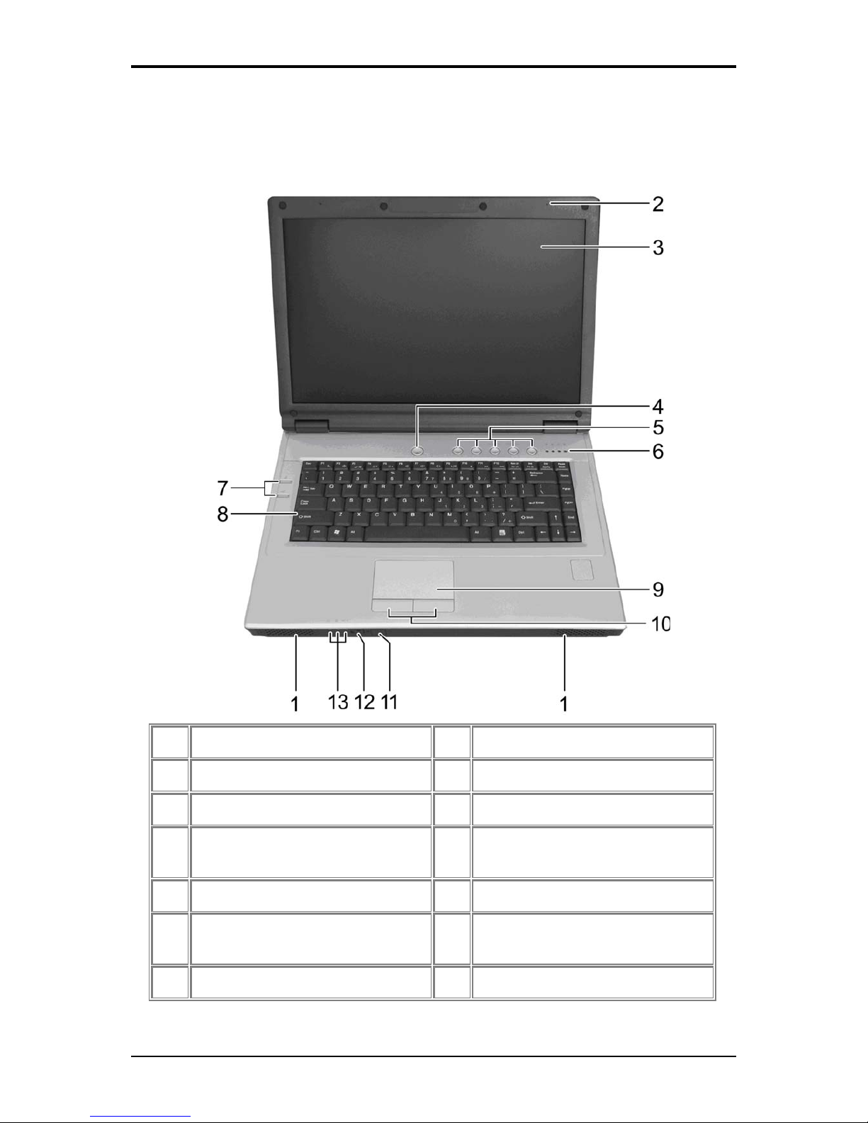
1.1 Front Side
The following picture shows the front side of the notebook.
1 Internal Speakers 8 Keyboard
2 Built-in Microphone 9 Touch Pad
3 Display 10 Touch Pad Buttons
4 Power Button 11 Consumer Infrared Receiver
(optional)
5 Easy Buttons 12 Wireless Communication Switch
6 Status LEDs 13 Device Status Indicators/Power
Status
7 Power USB / Q-Charging Buttons
Page 23
1 Introducing Your Notebook
1-2
1.1.1 Internal Speakers
The built-in speakers support stereo audio.
1.1.2 Built-in Microphone
The built-in microphone allows you to communicate without connecting an external
microphone.
1.1.3 Display
Your display is a 15.4” COLOR TFT WXGA LCD.
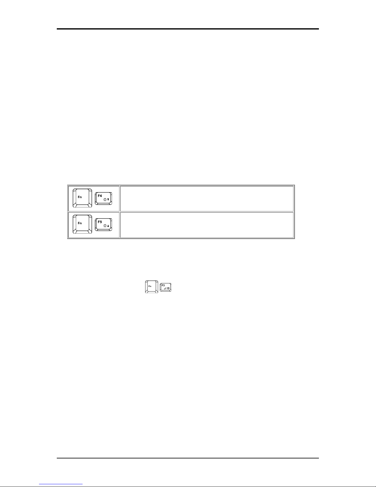
1.1.3.1 Adjusting the Brightness
To conserve power when running your notebook from the battery, set the brightness to the
lowest comfortable setting using the keyboard shortcuts.
Brightness Down
Brightness Up
1.1.3.2 Using an External Monitor or Television
When you start your notebook with an external display device such as an external monitor
or television attached and turned on, the image may appear on either the display or the
external device.
Alternatively, you can press
to switch the video image to the display only, the
display and the external device simultaneously, or the external device only.
1.1.3.3 Setting the Display Resolution
To view a program at a specific resolution, both the video controller and display must
support the program and the necessary video drivers must be installed.
Before changing any of the original display settings, note the original settings for future
reference.
Click Start > Control Panel > Appearance and Personalization > Adjust screen
resolution.
You can try different settings for screen resolution and color quality.
If you choose a resolution or color depth that is higher than the display supports, the settings
will automatically adjust to the closest possible setting.
Page 24
1 Introducing Your Notebook
1-3
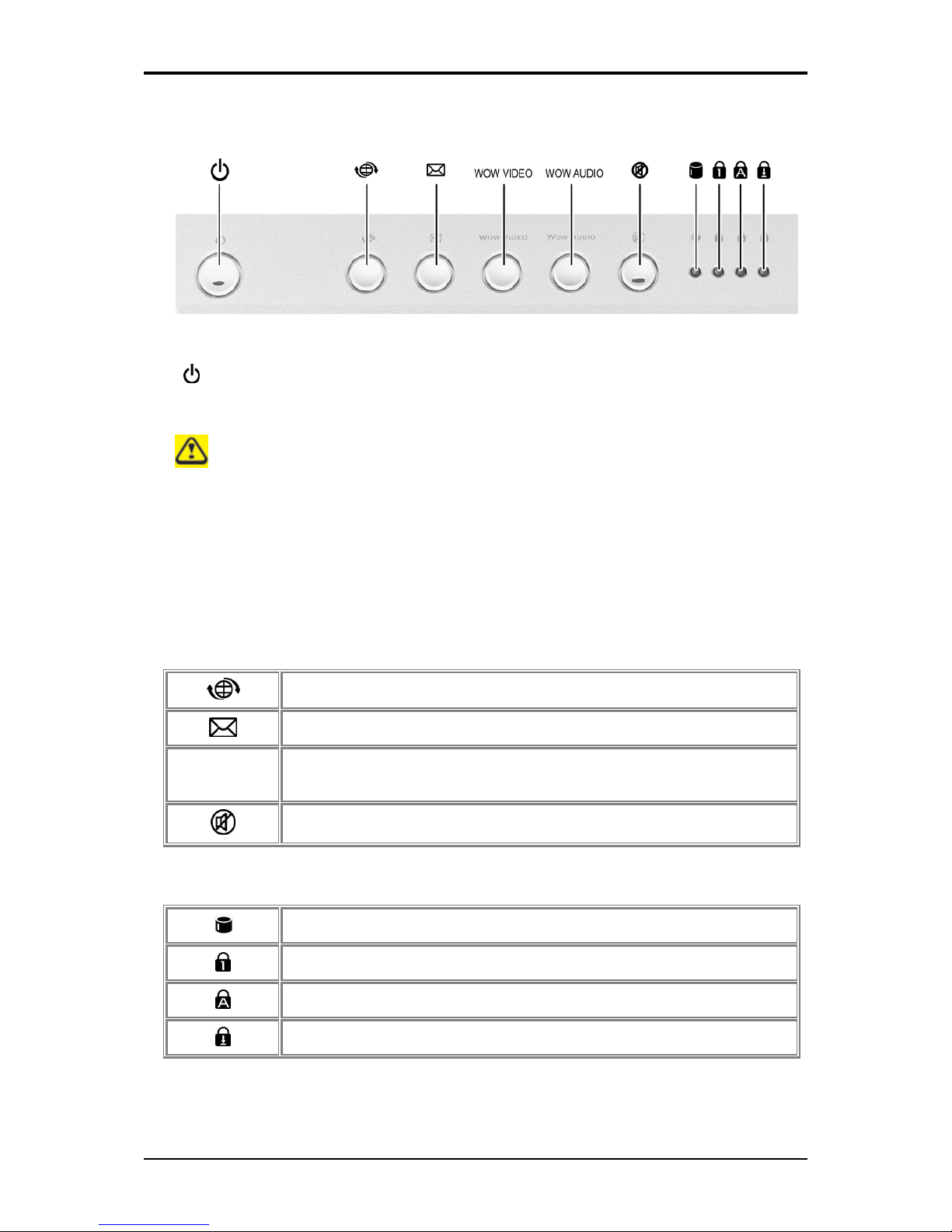
1.1.4 Top Panel Buttons and LEDs
- Power Button:
Press to turn your notebook on. For more on power settings, see 2.3 Power
Management.
Windows Vista, which comes preinstalled, goes into the shutdown sequence
automatically if you press the power button while on.
In Windows Vista, you can configure this in Control Panel > System and
M
aintenance or Hardware and Sound > Power Options > Change plan settings >
Change advanced power settings.
- Easy Buttons:
The notebook offers these buttons for quick launch programs and functions.
Internet access button
Email button
Wow Video
Wow Audio
Wow Video/Audio
Mute button
- Keyboard Indicators:
HDD access indicator
Num Lock On/Off indicator
Caps Lock On/Off indicator
Scroll Lock On/Off indicator
Page 25
1 Introducing Your Notebook
1-4
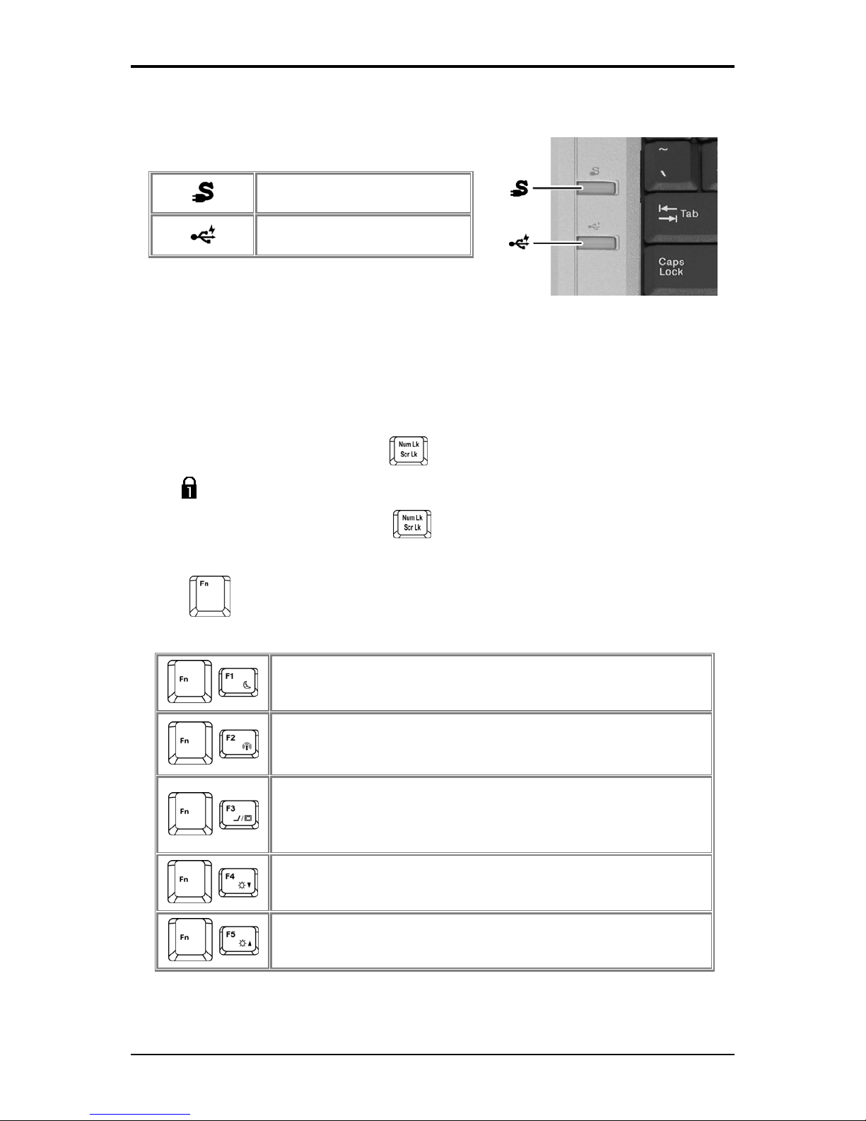
1.1.5 Left Panel Buttons
USB Buttons
Q-Charging button
Power USB button
1.1.6 Keyboard
The keyboard includes a numeric keypad and the Microsoft® Windows® logo key.
1.1.6.1 Numeric Keypad
Keypad numbers and symbols are marked in blue on the lower right edge of the keypad
keys.
To enable the numeric keypad, press .
The indicator will light when the numeric lock is on.
To disable the numeric keypad, press again.
To use the primary function of a dual-function key when the numeric keypad is enabled,
press and the desired key.
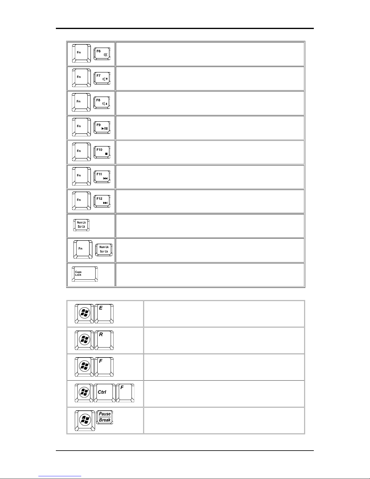
1.1.6.2 Keyboard Shortcuts
Sleep
Wireless/Bluetooth On/Off
To enable this function, you need to install Wireless Select Switch
Switches Display Mode (LCD > CRT > TV > LCD + CRT
Simultaneous > LCD+TV Simultaneous). Switches the video image
to the next display or both displays simultaneously.
Brightness Down
Brightness Up
Page 26
1 Introducing Your Notebook
1-5
Mute
Audio Volume Down
Audio Volume Up
Play/Pause
Stop
Fast Rewind
Fast Forward
Number Lock
Scroll Lock
Caps Lock
1.1.6.3 Windows Logo Key Functions
Opens Windows Explorer
Opens the Run dialog box
Opens the Search Results dialog box
Opens the Search Results - Computers dialog box (when
your notebook is connected to a network)
Opens the System Properties dialog box
Page 27
1 Introducing Your Notebook
1-6
To adjust keyboard operation, including character repeat rate, in the Control Panel click
Hardware and Sound > Keyboard.
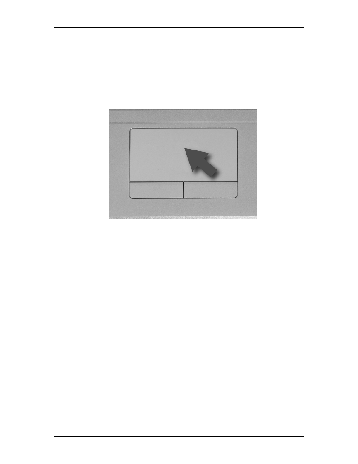
1.1.7 Touch Pad
The touch pad works like a desktop mouse. The Touch Pad responds to the movements and
pressure of your finger, allowing you to move the cursor around the screen, in the same way
you would with a mouse.
Place your fingers on the keyboard in the normal typing position.
You can use the Touch Pad by moving either your right or left thumb off the space bar and
on to the Touch Pad.
Gently move your thumb across the Touch Pad in the direction you want the cursor to move.
The Touch Pad buttons have the same function as mouse buttons. Clicking these buttons
makes selections, drags objects, or performs a variety of other functions depending on the
software. To select an object, first move the pointer over the object you want to select, and
then press the left button one time and release it. The functionality of these buttons depends
on your software.
Double-clicking is a common technique for selecting objects or launching programs.
You may also select object or execute applications from icons by double tapping. This is
similar to double-clicking; instead of pressing the Touch Pad buttons, you tap the Touch Pad
itself.
1.1.7.1 Customizing the Touch Pad
To adjust Touch Pad settings, use the Mouse Properties window, which you can open by
clicking Control Panel > Hardware and sound > Mouse.
Select the desired settings and click Apply.
Click OK to save the settings and close the window.
Page 28

1 Introducing Your Notebook
1-7
1.1.8 Touch Pad Buttons
The left and right touch pad buttons perform the same functions as the left/right buttons of a
standard mouse.
Page 29

1 Introducing Your Notebook
1-8
1.1.9 Wireless Communication Switch
Turns the wireless communication function on or off. The wireless communication LED on
the front panel lights when the function is activated.
1.1.10 Device Status Indicators / Power Status
The LEDs on the front of notebook indicate the device and power status.
1 Power On (Blue)
2 Battery Charge (Blue/Amber)
3 Bluetooth (Amber)/Wireless (Blue)
4 Wireless Communication Switch
The flashing Power On LED indicates the notebook is in standby mode.
For detailed battery status, see 2.4 Battery.
Page 30

1 Introducing Your Notebook
1-9
1.2 Right Side
The following picture shows the right side of the notebook.
1 Optical Media Drive
2 USB Ports
3 AC Adapter Connector
Page 31

1 Introducing Your Notebook
1-10
1.2.1 Optical Media Drive
The optical media drive provides a means for you to import/export data into/from your
computer. Depending on the configuration of your computer, you may either be able to
record or play CDs and DVDs.
1.2.2 USB Port
Use this port to connect a USB device, such as a mouse, external keyboard, or
printer to the computer.
USB is a peripheral expansion standard that supports data-transfer rates up to 480
M
bps. USB peripherals have a single standard for cables and connectors. You can
install and remove USB devices while the computer is on. This is called "hot
swapping".
1.2.3 AC Adapter Connector
Use this connector to attach the AC adapter to your notebook. You can connect
an AC adapter when your notebook is switched on or off.
While the AC adapter works with electrical outlets worldwide, power connectors
and power strips vary by country. Ensure you use a compatible cable or correctly
connect the cable to the power strip or electrical outlet. Failure to do so may cause
fire or damage to equipment.
Page 32

1 Introducing Your Notebook
1-11
1.3 Left Side
The following picture shows the left side of the notebook.
1 VGA Port
2 LAN Jack (Green/Amber)
3 Modem Jack
4 S-Video out Port
5 High Power USB Ports
6 IEEE 1394 Port
7 New Card Slot
8 Multiple Digital Media Slot
9 Microphone Jack
10 Headphone Jack
Page 33

1 Introducing Your Notebook
1-12
1.3.1 VGA Port
Use this port to connect an external monitor to your computer. See 1.1.3
Display. It doesn’t support CMOS and DOS modes.
1.3.2 LAN Jack
The RJ-45 network jack allows you to connect your notebook to a local area
network (LAN).
Be careful not to plug the telephone line into the slightly larger network connector.
1.3.3 Modem Jack
The modem jack allows you to connect the notebook to a telephone line with a
standard RJ-11 connector.
1.3.4 S-Video out Port
The S-Video out port allows you to connect an external display device, like a
TV set or device which has S-video port, to the notebook.
1.3.5 High Power USB Port
High-power USB ports can provide power for devices that draw more than
100mA from the bus line, such as cameras and external hard disks.
1.3.6 IEEE 1394 Port
The IEEE 1394 port allows you to connect devices that utilize IEEE 1394
technology to your computer. This technology is widely used in consumer
products such as digital cameras.
Page 34

1 Introducing Your Notebook
1-13
1.3.7 New Card Slot (For Express Card)
Supports 54mm type PCI Express Card.
1.3.7.1 PCI Express Card Types
The New Card slot supports one 54mm type PCI Express Card. It supports both USB 2.0
and PCI Express technology, which improves bus speed in data transfer and requires less
power than PC Cards.
A PCI Express Card is not a bootable device.
1.3.7.2 Installing a PCI Express Card
PCI Express Cards, with hot-plug feature, allow you to install and remove cards when your
notebook is running. The card will be detected automatically when installed.
Usually Express Cards have a mark or symbol to show which end to insert into the slot.
Insert the card according to the orientation symbol, and slide the card into the slot. Check
the documents that came with your card if the orientation is unclear.
1. Press to release the dummy card from the New Card slot.
2. Hold the PCI Express card with its orientation symbol pointing into the slot and the
topside of the card facing up.
3. Slide the card into the slot until it clicks into the connector.
4. If you encounter too much resistance, do not force the card. Check the card
orientation and try again.
Page 35

1 Introducing Your Notebook
1-14
1.3.7.3 Removing a PCI Express Card
1. Push the card all the way to in to release it.
2. Pull the card out of the slot.
1.3.8 Multiple Digital Media Card Slot
Supports one SD/MMC/MS card, which is used in digital still camera and various forms of
portable information equipment.
1.3.8.1 Adding and Removing SD/MMC/MS Cards
Before removing an SD/MMC/MS card, stop it running from the configuration
utility on the taskbar. Failure to do so could result in data loss.
Insert the SD/MMC/MS card into the card reader slot.
To remove the SD/MMC/MS card, push it in gently, it ejects automatically.
1.3.9 Audio Ports
You can connect a headphone or an external speaker to the port and a microphone to the
port. The built-in speakers are disabled when a device is connected to the port.
Page 36

1 Introducing Your Notebook
1-15
1.4 Rear Side
The following picture shows the rear side of the notebook.
Kensington Lock
Page 37

1 Introducing Your Notebook
1-16
1.5 Bottom Side
The following picture shows the bottom side of the notebook.
1 Battery Pack
2 Battery Release Latch
3 HDD Cover
4 Battery Lock Switch
5 Thermal Cover
6 Memory Module Cover
Page 38

1 Introducing Your Notebook
1-17
1.5.1 Battery Pack
With a charged battery pack installed, you can use your notebook without connecting it to
an electrical outlet. For more details, see 2.4 Battery.
To remove the Battery Pack:
1. Move the Battery Lock Switch to the right (Unlock position).
2. Slide the Battery Release Latch to the left and gently pry the Battery Pack from the
computer chassis.
1.5.2 Battery Release Latch
The Battery Release Latch secures the battery pack. To release, slide the latch and then
remove the battery pack from the bay.
Page 39

1 Introducing Your Notebook
1-18
1.5.3 Memory Modules
You can add more memory modules to your computer to improve its performance.
To install a memory module:
1. Make sure the computer is turned off.
2. Remove the two screws securing the memory module cover.
3. Lift off the memory module cover.
4. There are two memory module ports here. The first one is already occupied by your
computer’s current memory module. Place the new memory module in the second
slot, matching up the notch along its connector rim with the tooth in the connection
slot.
5. When the module is secured, press down gently until it snaps into place.
Depending on how much additional memory you require, you may need to replace
the original memory module.
To remove a memory module:
1. Make sure the computer is turned off.
2. Remove the two screws securing the memory module cover.
3. Lift off the memory module cover.
4. Pop out the two silver latches holding the memory module into place. The module
pops up.
5. Grasp the outer edges of the memory module with thumb and forefinger, and then
gently remove it.
Page 40

Page 41

2
Chapter 2
Operating Your Notebook (Vista)
Page 42

2 Operating Your Notebook (Vista)
2-1
2.1 Networks
To access a network:
At the office, you can access a network via the built-in PCI-E LAN.
For specific information about connecting to the LAN or WAN, consult your systems
administrator.
If you are working at home or while traveling, you need a dial-up connection. Ask your
system administrator for the telephone number of the network.
To set up the connection, go to Start > Control Pa nel > Network and Internet > Network
and Sharing Center. Click Set up a connection or network on the left pane of the
Network and Sharing Center window.
Choose a connection option and follow the on-screen instructions to set up your network
connection.
Page 43

2 Operating Your Notebook (Vista)
2-2
2.2 Playing CDs and Movies
2.2.1 Inserting Discs
B
e careful not to press down on the drive tray when opening or closing it. When the
drive is not in use, keep the tray closed.
Do not move the computer when playing CDs or DVDs.
To insert a disc, do the following:
Press the eject button on the front of the drive.
Pull the tray out.
With the label side up, place the disc in the center of the tray.
Snap the disc onto the spindle.
Gently push the tray back into the drive.
If your notebook has a CD-RW/DVD or DVD, you can watch movies.
For more information on playing CDs or watching movies, click Help on the CD player
software or DVD player software.
2.2.2 Adjusting the Volume
If you do not hear anything when playing a CD or DVD, check that the speakers are
not muted.
Start > All Programs > Accessories > Windows Mobility Center.
In the Windows Mobility Center window, click and drag the bar in the Volume column
and slide it left or right to decrease or increase the volume.
Audio Volume Down
Audio Volume Up
2.2.3 Adjusting the Picture
If you receive an error message that the current resolution and color depth are using too
much memory and preventing DVD playback, adjust the display properties:
Start > Control Panel > Appearance and personalization > Personalization> Display
Settings.
In the Display Properties window, click and drag the bar in Resolution section to change
the setting to 1024 x 768 pixels.
Page 44

2 Operating Your Notebook (Vista)
2-3
Click the pull-down menu under Colors, select Medium (16 bit), and click OK.
Page 45

2 Operating Your Notebook (Vista)
2-4
2.3 Power Management
2.3.1 Managing Your Notebook’s Power
See 2.4 Battery for more information on getting the best performance from battery
packs.
Use your notebook connected to an electrical outlet as often as possible as battery
life expectancy is affected by the number of times it is charged.
Your computer comes with built-in power management. You can configure it, through the
Power Options program in the Control Panel, to sleep, hibernate, and wake according to
specific situations.
The Advanced settings can be accessed via Start > Control Panel > System and
Maintenance > Power Options.
On the Select a power plan page, click Change plan setting under the plan that you want
to change.
Click Change advanced power settings. Expand the Power buttons and lid category to
configure the settings.
When leaving your notebook unattended for long periods, place it in standby or hibernate
mode. You can exit either power management mode by pressing the power button.
2.3.2 Power Management Modes
2.3.2.1 Sleep Mode
This mode conserves power by switching off the hard drive and display after a preset period
of inactivity (a time-out). When sleep mode is exited, your notebook will return to the same
operating state it was before entering sleep.
I
f your notebook loses power from both the electrical outlet and the battery while in
sleep mode, data may be lost.
To enter sleep mode in Windows Vista:
Start > X > Sleep. Or
Set your notebook to enter sleep mode:
• When you close the lid of your notebook
• When you press the power button
• When you press the start menu power button
The settings can be accessed via Power Options: Advanced settings window. See 2.3.1
Managing Your Notebook’s Power.
Page 46

2 Operating Your Notebook (Vista)
2-5
To exit sleep mode, press the power button. You cannot exit sleep mode by pressing a key or
touching the Touch Pad.
2.3.2.2 Hibernate Mode
In Hibernate mode, power is conserved by system data being copied to the hard drive, and
your notebook is completely shut down. When Hibernate mode is exited, your notebook
will return to the same operating state it was in before entering Hibernate mode.
Hibernate mode can be enabled/disabled in the Power Options window.
If enabled, your notebook will go into Hibernate mode if the battery charge level becomes
critically low.
Depending on how you set the Power Management Options in the Power Options window,
use one of the following methods to enter hibernate mode:
• When you close the lid of your notebook
• When you press the power button
• When you press the Start menu power button
• Start > X > Hibernate.
The settings can be accessed via Power Options: Advanced settings window. See 2.3.1
Managing Your Notebook’s Power.
To exit Hibernate mode, press the power button. You cannot exit Hibernate mode by
pressing a key or the Touch Pad.
2.3.3 Power Options Properties
To access the Windows Power Options window:
Start > Control Panel > System and Maintenance > Power Options
2.3.3.1 Select a power plan
Windows Vista provides three preset power plans, Balanced, Power saver, and High
performance. Each plan has different time-out settings for turning off the display and
entering sleep mode. You do not need to make any further adjustments to set the
performance level.
To change setting for the plan, click the following three items on the left pane of the Power
Options window.
• Choose when to turn off the display
• Change when the computer sleeps
• Adjust the display brightness
After selecting a plan, you can see the percentage of battery charge remaining and active
power plan by moving the mouse pointer over the battery meter icon on the taskbar.
Page 47

2 Operating Your Notebook (Vista)
2-6
For more information on changing advanced power settings, see the Windows Help and
Support.
To maximize battery power, use the Power saver plan.
2.3.3.2 Power buttons and password protection
Select Requir e a password on wakeup, Choose what the power buttons does, or Choose
what closing the lid does from the left pane of the Power Options window. There are two
main settings in this section:
• Power button and lid settings
• Password protection on wakeup
Depending on your operating system, program the following functions by clicking an
option from the corresponding pull-down menu in Advanced settings window, and then
clicking OK to save your settings and close this window.
For more information on accessing the Advanced settings window, See 2.3.1 Managing
Your Notebook’s Power.
• Set the computer to Do nothing / Sleep / Hibernate / Shutdown when you
press the power button.
• Set the computer to Do nothing / Sleep / Hibernate / Shutdown when you
close the laptop lid
• Select the password requirement when the computer wakes from sleep.
2.3.3.3 Create a power plan
Besides the three preset power plans offered in Windows Vista, you can also customize your
own power plan. Select Create a power plan on the left pane of the Power Options window
to begin configuring your power settings.
2.3.4 SpeedStep
Your notebook is equipped with SpeedStep technology to better manage power
consumption. It changes the processor speed to find the best balance between your
computing performance and power consumption needs. Higher speeds enjoy better
performance, while slower speeds conserve more power.
In Windows Vista, the processor's performance level depends on the Power Scheme you
select (see 2.3.3 Power Options Properties). You do not need to make any further
adjustments to set the performance level. Each preset power scheme has different time-out
settings for entering sleep mode, hibernate mode, turning off the display, and turning off the
hard drive.
Page 48

2 Operating Your Notebook (Vista)
2-7
For example, the Windows Vista automatically changes SpeedStep modes depending on if
you are running the computer on AC power or batteries in order to prolong battery usage
while still providing optimal performance.
You can also individually alter and save each of these settings and schemes if desired.
Choose from the following three power plans that best describes the desired relationship
between power and performance.
Windows Vista automatically chooses the SpeedStep mode to find the most appropriate
speed for your processor according to the type of plan you choose and your current system
demands.
Page 49

2 Operating Your Notebook (Vista)
2-8
2.4 Battery
2.4.1 Battery Performance
The performance of the battery can vary, depending on operating conditions. Your battery
may last less time if you are running power-intensive programs, playing CDs or DVDs, or
have high display-brightness settings.
The Power Management Options can be set to alert you when the battery charge is low.
Ensure any battery you use is compatible. Failure to do so may risk fire or
explosion. For more details on purchasing compatible batteries, contact your
notebook retailer.
B
atteries should never be disposed of with household waste. Contact your local
waste disposal or environmental agency for advice on disposing of used lithium-ion
batteries.
Only use the SQU-528, SQU-601, ID6, ID6-2600, IDST-9, CBPIL48, CBPIL52, or
CBPIL73 battery pack with this computer.
2.4.2 Checking the Battery Charge
Battery Status Indicator behavior
Charging Flashes blue
Fully Charged Solid blue
Critical Low Amber > approximately 3 minutes left; system beeps
2.4.3 Power Meter
The power meter indicates the remaining battery charge. When your notebook is running
on battery power, you can check the remaining battery charge, double click the
icon on
the taskbar. For more details, including how to make the icon appear on the taskbar if it is
not already, see 2.3 Power Management.
Page 50

2 Operating Your Notebook (Vista)
2-9
2.4.4 Low-Battery Warning
After a low-battery warning, save your work immediately, then connect your
notebook to an electrical outlet. Hibernate mode will begin automatically if the
battery runs completely out of power.
You will hear the low-battery warning when the battery charge is approximately 90 percent
depleted. Your notebook will beep once, indicating approximately 10 to 15 minutes of
battery operating time remain. If you do not connect your notebook to alternative power
source during that time, there will be a periodic beep. Your notebook will automatically
enter Hibernate mode if battery charge reaches a critically low level. For more information,
see 2.3 Power Management.
2.4.5 Charging the Battery
When connected to an electrical outlet, a completely discharged 6 cell battery
needs to be charged in 3.5 to 12 hours, and a 9 cell battery in 4.5 to 12 hours
(depending on whether your notebook is on or off and what programs, if any, are
running). You can leave the battery in your notebook as long as you like. The
battery’s internal circuitry prevents the battery from overcharging.
Before using the battery for the first time it must be charged. Connect the computer to an
electrical outlet and allow the battery to fully charge, indicated by the battery indicator light
on the front panel of the notebook.
Once a battery pack is fully charged for the first time, use your notebook on battery
p
ower until the battery discharges completely. This will extend battery life, and
helps ensure accurate monitoring of battery capacity.
If necessary, the battery will be charged whenever your notebook is connected to an
electrical outlet.
The battery will not be charged if it or your notebook is too hot, either from use or being in
a hot environment. If this occurs, the battery indicator will light amber. Disconnect your
notebook from any electrical outlet, and allow it and the battery to cool to room temperature.
You can then reconnect your notebook to the electrical outlet and charge the battery. The
battery indicator will also light amber if the battery is bad and needs replacing.
2.4.6 Removing the Battery
Before removing the battery, ensure your notebook is turned off.
Move the battery lock switch to the right (Unlock position).
Slide and hold the battery release latch.
Remove the battery.
Page 51

2 Operating Your Notebook (Vista)
2-10
2.4.7 Installing a Battery
Slide the battery into the bay.
Press it into place gently but firmly until the latch locks it into place.
Slide the battery lock switch back to the locked position.
2.4.8 Storing a Battery
If storing your notebook for an extended period of time, remove the battery. Fully charge the
battery before using your notebook again.
2.4.9 Working With Extra Battery Packs
If you spend a lot of time traveling, working without connecting your notebook to an
electrical outlet, it may be a good idea to carry additional battery packs so you can quickly
replace a discharged battery and continue working.
2.4.10 Maximizing Battery Life
A battery can be recharged many times, but over time it will lose its ability to hold a charge.
To maximize battery life:
• If you are not using your notebook for a long period, remove the battery.
• If you have a spare battery pack, alternate the batteries.
• Ensure your notebook is off when replacing the battery.
• Store spare battery packs in a cool, dry place, out of direct sunlight.
Page 52

2 Operating Your Notebook (Vista)
2-11
2.5 Advanced Charging Functions: Q-Charging &
Power USB Buttons
2.5.1 Q-Charging Button with Smart Battery Software
The Q-Charging button and Smart Battery software let the user determine how much the
battery is charged when connected to AC power.
2.5.1.1 Installing the Software
You must have Administrator’s rights to install the software. Double click setup.exe in the root
directory on the CD-ROM to begin installation. Once installation is complete, the system will
restart automatically. The software will be loaded automatically upon reboot.
2.5.1.2 Using the Software
Before you can use the Q-Charging button, you must first configure the Smart Battery software.
You can access the software via the Control Panel:
1. Click Start > Settings > Control Panel.
2. Double click the Smart Battery icon. The main screen appears:
v
Check to display the smart battery
icon in the s
y
stem tray
Click to close
windo
w
Click to appl
y
default settings
Click to apply
changes and
close windo
w
Click to close
window without
saving changes
Check the battery charging mode you require:
Battery Full Charging
: The battery is charge
d
to full capacity when connected to AC power.
The Q-Charging button is disabled.
Balanced
: The battery is charged up to 75% o
f
its capacity.
Extended Battery Life Cycle
: The battery is
charged up to 50% of its capacity.
Page 53

2 Operating Your Notebook (Vista)
2-12
2.5.2 Using the Q-Charging Button
Press the Q-Charging button to begin charging the battery to its maximum capacity. By
pressing the Q-Charging button, you override any settings made in the Smart Battery software.
When you press the Q-Charging button, a pop-up message will appear ‘Charging in progr ess.
Avoid disconnecting AC adaptor’. DO NOT disconnect the AC adaptor, as this may cause
irreversible damage to your battery and laptop.
2.5.3 Using the Power USB Button
The laptop is equipped with a power USB function, which allows you to increase the power
output when charging an external USB device, such as a mobile phone or PDA.
Press the Power USB button to increase the power output to 1 ampere. When not pressed,
power output is 0.5 ampere. You can also charge external USB devices when the laptop is
powered off, but this button must be pressed in order to do so.
Note: Power USB work at AC mode.
Page 54

2 Operating Your Notebook (Vista)
2-13
2.6 WOW Video & Audio
The Wow Video & Audio software lets the user switch between various video and audio
schemes, to best suit the media that is being played.
2.6.1 Installing the Software
You must have Administrator’s rights to install the software. Double click setup.exe in the root
directory on the CD-ROM to begin installation. Once installation is complete, the system will
restart automatically. The software will be loaded automatically upon reboot.
2.6.2 Using the Software
Press the Wow Video button on the front of the laptop to select the preferred video mode. Press
the button repeatedly to cycle through the available modes: Theater, Office, Photo, Normal,
User Define (see 2.6.3 Changing Software Settings for details).
Press the W ow Audio button on the front of the laptop to select the preferred audio mode. Press
the button repeatedly to cycle through the available modes: Flat, Classic, Speech, Pop.
2.6.3 Changing Software Settings
You can configure the Wow Video & Audio software via the Control Panel:
1. Click Start > Settings > Control Panel.
2. Double click the W ow Video Audio icon. The main screen appears:
Click to apply changes
and close window
Click to close window
without saving changes
Click to apply changes
immediately
Click to close
window
Click to select video
scheme
When the
User
Define video scheme
is selected, click to
modify gamma,
brightness, and
contrast
settings for
each color channel.
Click to select audio
scheme
Page 55

3
Chapter 3
Caring for Your Notebook
Page 56

3 Caring for Your Notebook
3-1
3.1 Caring for Your Notebook
Never spray cleaning products directly onto your notebook's case or display. Only
use products designed for cleaning computer displays.
3.1.1 Cleaning Your Notebook and Keyboard
Shut your notebook down, turn it off and disconnect it from the electrical outlet and any
external devices, such as a printer.
Remove the battery pack.
Use the brush attachment of your vacuum cleaner to gently remove dust from your
notebook's openings and keyboard.
Use a slightly moistened soft, lint-free cloth to wipe your notebook and keyboard. Use
only water or a recommended computer cleaner.
3.1.2 Cleaning the Display
Shut your notebook down, turn it off and disconnect it from the electrical outlet and any
external devices, such as a printer.
Remove the battery pack.
Use a slightly moistened soft, lint-free cloth to wipe your notebook's display. Use only
water or a recommended computer cleaner.
3.1.3 Cleaning the Touch Pad
Shut your notebook down, turn it off and disconnect from the electrical outlet and any
external devices, such as a printer.
Remove the battery pack.
Use a slightly moistened soft, lint-free cloth to carefully wipe the Touch Pad, being
careful not to allow any moisture into the gaps. Use only water or a recommended
computer cleaner.
3.1.4 Cleaning the CD/DVD Drive
Never touch the lens. Use only compressed air to clean the lens.
If you experience problems playing CDs or DVDs, including skipping, clean the unlabelled
side of the disc with a soft, lint-free cloth or using a commercial product.
Page 57

3 Caring for your Notebook
3-2
3.1.5 Precautions
• Do not spill liquids on the keyboard. If liquid is spilt on the keyboard, turn your
notebook off immediately. Leave off overnight to let it completely dry out
before using it again.
• Do not turn off your notebook if a drive light indicates a drive is active. Turning
off your notebook while it is reading from or writing to a disk may damage the
disk, the drive, or both.
• Keep your notebook and disks away from objects that generate strong magnetic
fields, such as stereo speakers. Information on disks is stored magnetically.
Placing a magnet too close to a disk can erase important files.
• Scan all new files for viruses. This precaution is especially important for files
you receive via email, disk or download from the Internet. You will need a
special program to scan for viruses. For further information, talk to your
computer dealer.
Page 58

3 Caring for Your Notebook
3-3
3.2 Traveling
3.2.1 Identifying Your Notebook
Attach a nametag or business card to your notebook, or use a permanent marker or stencil to
write a unique identifying mark (such as your driver's license number) on the case.
Create a file on the Desktop called if found. Place information such as your name, address,
and telephone number in this file.
Contact your credit card company, and ask if it offers coded identification tags.
3.2.2 Packing Your Notebook
Remove any external devices attached to the computer and store them in a safe place.
Fully charge the main battery and any spare batteries you plan to carry with you.
Turn off the computer or put the computer into hibernate mode.
Disconnect the AC adapter.
Remove any extraneous items, such as paper clips, pens, and paper, from the keyboard and
then close the display.
Pack your notebook and accessories in their carry case.
Avoid packing the computer with items such as shaving cream, colognes, perfumes, or food.
Protect the computer, the batteries, and the hard drive from hazards such as extreme
temperatures, dirt, dust, liquids, or overexposure to sunlight.
Pack the computer so that it does not slide around in the trunk of your car or in an overhead
storage compartment.
When traveling by air, never check in your notebook as baggage.
3.2.3 Setting a Password
To provide extra protection for your data and documents, it is advisable to set a password.
As your notebook is booting (starting up), press F2 to view the BIOS Setup Utility. Use the
right arrow key to highlight Security.
Use the down arrow key to select: Set Supervisor Password. Press Enter.
Type your password, press Enter and re-type to confirm. Press Enter. Your changes will be
saved. Press Enter to continue.
Use the right arrow key to select Exit, use the down key to select Exit Saving Changes.
Press Enter and Yes. Your notebook will now boot as normal.
To enable password protection on Boot, use the down key to select Password on
boot. Press Enter and select Enabled.
Page 59

3 Caring for your Notebook
3-4
3.2.4 Travel Tips
• If you are traveling abroad, carry proof of ownership—or of your right to use the
computer if it is company-owned—to speed your passage through customs.
Investigate the customs regulations of the countries you plan to visit and
consider acquiring an international carnet (also known as a merchandise
passport) from your government.
• Ensure that you know which electrical outlets are used in the countries you will
visit, and prepare the appropriate power adapters.
• Check with your credit card company for information about the kinds of
emergency travel assistance it offers to users of portable computers.
• When traveling by air, ensure that you have a charged battery available in case
you are asked to turn on the computer.
• Before you use the computer on an airplane, verify that such usage is permitted.
Some airlines forbid the use of electronic devices during the flight. All airlines
forbid the use of electronic devices during takeoff and landing.
Never walk your notebook through a metal detector. Send it through an X-ray
machine, or have it manually inspected.
3.2.5 If Your Notebook is Lost or Stolen
Call a law enforcement agency to report your notebook lost or stolen. Ask that a case
number be assigned and write down the number, along with the name, address, and
telephone number of the law enforcement agency. If possible, obtain the name of the
investigating officer.
If the notebook belongs to a company, notify the security office of the firm.
Page 60

Page 61

Chapter 4
The BIOS Setup Program
Page 62

4 The BIOS Setup Program
4-1
4.1 Introduction
The BIOS (Basic Input and Output System) Setup program is a menu driven utility
that enables you to make changes to the system configuration and tailor the
operation of your notebook to your individual work needs. A ROM-based
configuration utility displays the system's configuration status and provides you
with a tool to set system parameters. These parameters are stored in nonvolatile
battery backed-up CMOS RAM, which saves this information even when the power
is turned off. When the computer is turned back on, the system is configured with
the values found in CMOS. Via easy-to-use menus, you can configure such items as:
Hard drives, diskette drives and peripherals
Video display options
Password protection from unauthorized use
Boot devices
The settings made in the Setup program intimately affect how the notebook
performs. It is important, therefore, to first understand all the available options, and
second, to make settings appropriate for the way you use the notebook. This chapter
guides you through the Setup program by providing clear explanations for all Setup
options.
A standard configuration has already been set in the Setup program by the factory
technicians. However, eventually you may want to customize your system to suit
your own performance needs. It is recommended that you read this chapter and
become familiar with the configurations that can be made in the BIOS.
The next section explains how to move around in the Setup program, as well as how
to specify and save your new settings. A brief discussion of the optional settings
among the different submenus follows.
Page 63

4 The BIOS Setup Program
4-2
4.2 Navigating through the BIOS Setup
Program
¾ Accessing the BIOS Setup Program
¾ Launching Submenus
¾ Saving Changes and Exiting the Setup Program
The Setup program has been designed to make it as easy to use as possible. It is a
menu driven program, which means you can scroll through the various directories
and make your selections among the various predetermined choices. If you
accidentally configure a setting, use the BIOS hot keys to return to the previous
value. The hot keys are discussed in more detail later in this chapter.
When turning on the notebook for the first time you may be prompted to run the
BIOS Setup program. A warning message may appear on the screen if the hardware
configuration is changed or the POST fails. This message will inform you of any
errors or invalid settings and prompt you to run the Setup program to correct the
problem.
Even if you are not prompted by a message instructing you to use the Setup program,
at some time in the future you may want to change the configuration of your
computer. For example, you may want to make changes to the display option
settings or enable the notebook's password function for security purposes. It will
then be necessary to reconfigure your system using the Setup program so that the
computer can recognize these changes.
The list below gives a few examples of reasons why you may want or need to run the
BIOS Setup program.
You have set up the computer for the first time and you got a message stating
that you should run the BIOS Setup program.
You want to redefine the communication ports to prevent any conflicts.
You want to change the password or make other changes to the security setup.
The few examples listed above are by no means complete.
Page 64

4 The BIOS Setup Program
4-3
4.2.1 Accessing the BIOS Setup Program
To access the BIOS Setup program, press the [F2] key as soon as the computer starts
upTthe Phoenix BIOS screen displays.
Phoenix TrustedCore(tm) Setup Utility
Main Advanced Security Boot Exit
Item Specific Help
System Time: [19:34:35]
System Date: [01/01/2005]
<Tab>, <Shift-Tab>, or
<Enter> selects field.
Hard Disk: Hard Disk Model Name
Quiet Boot: [Enabled]
System Memory: 640 KB
Extended Memory: 1022 MB
BIOS Version: XXXXX
Language: [English (US)]
F1 Help ↑↓ Select Item F5/F6 Change Values F9 Setup Defaults
Esc Exit ←→ Select Menu Enter Select 4 Sub-Menu F10 Save and Exit
The Menu Bar
The top of the Setup screen has a menu bar with the following selections:
Main Allows the user to configure standard IBM PC AT system
parameters.
Advanced Allows the user to configure advanced system settings.
Security Allows the user to configure security system settings.
Boot Allows the user to specify the order in which the notebook is to
check for a device to boot the system.
Exit Allows the user to save CMOS setting and exit the Setup
program.
Page 65

4 The BIOS Setup Program
4-4
To move between menu bar items, use the [◄] and [►] arrow keys until the desired
item is highlighted. For example, if you want to move from the Main menu to the
Advanced menu, press the right arrow key [►] once.
Item Specific Help
To the right of the Setup screen, you will notice an item specific help bar. For each
item that you select on the menu, the bar informs of its specific function as well as
the hot keys related to that item and/or submenu.
4.2.2 Launching Submenus
A submenu contains additional options for a field parameter. To call up a submenu,
simply move the highlight to the desired field and press the [Enter] key. The
submenu opens.
If you are a first time user or are not familiar with BIOS Setup program, it is highly
recommended that you take a few minutes to familiarize yourself with each of the
submenus and their corresponding functions. If you accidentally make unwanted
changes to the current configuration, go to the Exit menu and select Discard
Changes.
4.2.3 Saving Changes and Exiting the Setup Program
Refer to the Exit Menu section of this chapter for detailed information on saving
changes and exiting the Setup program.
Page 66

4 The BIOS Setup Program
4-5
4.3 The Main Menu
When the Setup program is accessed, the Information screen appears. It displays the
following pieces of information regarding your current system:
Phoenix TrustedCore(tm) Setup Utility
Main Advanced Security Boot Exit
Item Specific Help
System Time: [19:34:35]
System Date: [01/01/2005]
<Tab>, <Shift-Tab>, or
<Enter> selects field.
Hard Disk: Hard Disk Model Name
Quiet Boot: [Enabled]
System Memory: 640 KB
Extended Memory: 1022 MB
BIOS Version: XXXXX
Language: [English (US)]
F1 Help ↑↓ Select Item F5/F6 Change Values F9 Setup Defaults
Esc Exit ←→ Select Menu Enter Select 4 Sub-Menu F10 Save and Exit
System Time and System Date
The hour is displayed with 24-hour format. The values set in these two
fields take effect immediately.
Hard Disk
The hard disk information is displayed with the manufacturer and model
name.
Quiet Boot
Enabled
: Customer logo is displayed; Summary screen is disabled.
Disabled: Customer logo is not displayed; Summary screen is enabled.
System Memory
This field reports the memory size of system base memory. The size is
fixed to 640KB.
Page 67

4 The BIOS Setup Program
4-6
Extended Memory
This field reports the memory size of the extended memory with an
integer in the system, but 32Bit SMI will occupy 1 MB and UMA frame
buffer (Integrated VGA uses only).
Extended Memory size = Total memory size – 1 MB – 1 MB – UMA
frame buffer
BIOS Version
This field displays current version of the BIOS.
Language
Currently only English is supported.
Page 68

4 The BIOS Setup Program
4-7
4.4 The Advanced Menu
Selecting Advanced on the menu bar displays the Advanced Menu. Each field on
this menu is covered below.
Phoenix TrustedCore(tm) Setup Utility
Main Advanced Security Boot Exit
Item Specific Help
AHCI Configuration: [Enabled]
Total Graphics Memory: 512 MB
Legacy USB Support: [Enabled]
Enhanced AHCI:
WinXP-SP1+IAA driver
supports AHCI mode.
F1 Help ↑↓ Select Item F5/F6 Change Values F9 Setup Defaults
Esc Exit ←→ Select Menu Enter Select 4 Sub-Menu F10 Save and Exit
AHCI (Advanced Host Configuration Interface) Configuration
Disabled: Disables the AHCI mode.
Enabled: Enables the AHCI mode.
Total Graphics Memory
This field displays the total onboard graphics memory.
Legacy USB Support
Disabled: Disables the legacy USB support.
Enabled: Enables the legacy USB support.
Page 69

4 The BIOS Setup Program
4-8
4.5 The Security Menu
The notebook's advanced security system allows you to set a password to prevent
unauthorized access to system resources, data, and the BIOS Setup program. This
section covers each Security parameter. Selecting Security from the menu bar
displays the Security menu.
A Note about Passwords
The BIOS Setup program allows you to specify passwords in the Security menu.
The passwords control access to the BIOS and certain Security menu options during
system startup.
Passwords are not case sensitive. A password can be entered using either upper or
lower case letters; it makes no difference. When you choose your password, it
should be composed of alphanumeric characters (a-z, 0-9) and be eight characters in
length.
NOTE: The supervisor password must be set before the user password can be set.
Set Supervisor Password… / Set User Password…
Phoenix TrustedCore(tm) Setup Utility
Main Advanced Security Boot Exit
Item Specific Help
Supervisor Password Is: Clear
User Password Is: Clear
Set Supervisor Password: [Enter]
Supervisor password
controls access to the setup
utility.
Set User Password: [Enter]
Password on boot: [Enabled]
Built-in HDD1 Status Clear
Built-in HDD1 Password Select [User Only]
Set HDD User Password [Enter]
Trusted Platform Support(*) [Disabled]
F1 Help ↑↓ Select Item F5/F6 Change Values F9 Setup Defaults
Esc Exit ←→ Select Menu Enter Select 4 Sub-Menu F10 Save and Exit
These fields allow you to set the System Password. The System Password allows
full access to the BIOS Setup menus. To set the Supervisor password, highlight this
field and press [Enter].
Page 70

4 The BIOS Setup Program
4-9
Type the password and press the [Enter] key. You can type up to eight alphanumeric
characters. Symbols are ignored.
To confirm the password, type the password again and press the [Enter] key.
Supervisor Password Is / User Password Is
This field displays if the Supervisor/User Passwords is set.
Set System Password is set.
Clear System Password is not set.
Set Supervisor Password / Set User Password
Enter this field always shows the message.
While this field is highlighted, press [Enter]. The following message is shown:
Set Supervisor Password:
Enter New Password [ ]
Confirm New Password [ ]
If there is an existing password then setup will prompt with the following window
instead and the current password will be required to be entered at first:
Set Supervisor Password:
Enter Current Password [ ]
Enter New Password [ ]
Confirm New Password [ ]
User can type password in field of Enter New Password, and re-enter password in
field of Confirm New Password for verification.
If verification OK:
Setup Notice
Changes have been saved.
[Continue]
The supervisor password is saved after pressing [Enter].
If verification fails:
Setup Warning
Passwords do not match.
Re-enter password.
[Continue]
The formats of the password are as follows:
Length: No more than eight characters.
Characters: Alphanumeric keys only. The shift status, Ctrl, Shift, Alt, and capitals,
are ignored.
Page 71

4 The BIOS Setup Program
4-10
Password on boot
If password on boot is required, the password must be set otherwise it cannot be
enabled. Enable this field to have setup prompt for the password when the computer
boots.
Built-in HDD1 Status
Set HDD Password is set.
Clear HDD Password is not set.
Built-in HDD1 Password Select
User Only For normal user entering HDD password.
User+Master Master password must be set first before user password
can be configured.
Set HDD User Password / Set HDD Master Password
Enter this field always shows the message.
While this field is highlighted, press [Enter]. The following message is shown:
Set HDD Master Password
Enter New Password [ ]
Confirm New Password [ ]
If there is an existing password then setup will prompt with the following window
instead and the current password will be required to be entered at first:
Set HDD Master Password
Enter Current Password [ ]
Enter New Password [ ]
Confirm New Password [ ]
User can type password in field of Enter New Password, and re-enter password in
field of Confirm New Password for verification.
If verification OK:
Setup Notice
Changes have been saved.
[Continue]
The HDD password is saved after pressing [Enter].
If verification fails:
Setup Warning
Passwords do not match.
Re-enter password.
[Continue]
Page 72

4 The BIOS Setup Program
4-11
If password on boot is required, the password must be set otherwise it cannot be
enabled.
The formats of the password are as follows:
Length: No more than 8 characters.
Characters: Alphanumeric keys only. The shift status, Ctrl, Shift, Alt, and Capital,
are ignored.
Page 73

4 The BIOS Setup Program
4-12
4.6 The Boot Menu
This menu allows the user to decide the order of boot devices to load the operating
system. Bootable devices include the diskette drive in module bay, the onboard hard
disk drive and the CD-ROM in module bay.
Phoenix TrustedCore(tm) Setup Utility
Main Advanced Security Boot Exit
Item Specific Help
HDD Hard Disk Model name
CD/DVD CD/DVD Drive Model name
FDD
LAN
Keys used to view or
configure devices:
Up and Down arrows
select a device.
<F5> and <F6> moves the
device up or down.
<Shift + 1> enables or
disables a device.
F1 Help ↑↓ Select Item F5/F6 Change Values F9 Setup Defaults
Esc Exit ←→ Select Menu Enter Select 4 Sub-Menu F10 Save and Exit
Page 74

4 The BIOS Setup Program
4-13
4.7 The Exit Menu
Phoenix TrustedCore(tm) Setup Utility
Main Advanced Security Boot Exit
Item Specific Help
Exit Saving Changes
Exit Discarding Changes
Load Setup Defaults
F1 Help ↑↓ Select Item F5/F6 Change Values F9 Setup Defaults
Esc Exit ←→ Select Menu Enter Select 4 Sub-Menu F10 Save and Exit
Exit Saving Changes
Allows the user to save changes to CMOS and reboot system. The following
message prompts the user to confirm after pressing [Enter] on the item.
Setup Confirmation
Save configuration changes and exit now?
[Yes] [No]
Yes: Exit SETUP and reboot
No: Go back to previous screen
Exit Discarding Changes
Allows the user to exit Setup without saving changes to CMOS. The following
message prompts the user to confirm after pressing [Enter] on the item.
Setup Warning
Configuration has not been saved!
Save before exiting?
[Yes] [No]
Page 75

4 The BIOS Setup Program
4-14
Load Setup Defaults
Allows the user loads default values in CMOS Setup. The following message
prompts the user to confirm after pressing [Enter] on this item.
Setup Confirmation
Load default configuration now?
[Yes] [No]
Select Yes to confirm or No to abort. You will then return to the setup screen.
Page 76

Page 77

5
Chapter 5
Troubleshooting
Page 78

5 Troubleshooting
5-1
5.1 Frequently Asked Questions
Q : My computer switches to hibernation mode much too quickly and I have to constantly hit
a key or move the mouse to bring back the screen. What can I do?
This is part of Windows Power Management. Access Power Management by clicking on Start /
Control Panel / Performance and Maintenance / Power Options, and change the time next to the
“Turn off monitor” option to the time you want. You have the choice of either adjusting time for the
power supply or for the battery.
Q : I’ve heard that cleaning and rearranging files on the hard drive will improve program’s
launch speed. How do I do this ?
Good disk maintenances can improve program launch speed. This normally includes deleting
unnecessary files, and defragmenting hard disk so that files can be more efficiently grouped.
Windows contains maintenance utilities for these tasks; run Disk Cleanup to remove unnecessary
files, and Disk Defragmenter to defragment fragmented file blocks. For more information about
these utilities, please refer to your Windows documentation.
Q : The dial tone volume of the internal fax/modem is too low. How can I increase its
volume?
Go to Start/Control Panel/Sounds, Speech, and Audio Devices, under Device volume, adjust your
speaker volume by controlling the volume bar.
Q : What kind of external microphone can I use with my notebook computer?
You will need to use a self-amplifying microphone.
Q : There are echoes coming from my speakers. What can I do?
Double click on the Speaker icon on the task bar. Then, under Microphone Balance, check the Mute
box.
Q : Because of a software problem, I was unable to shut the computer down from Windows,
I pressed the power button to power off the computer, but it didn’t work. How can I force a
power off?
Make sure you press the power button for at least 4 seconds. Normally, this will force the computer
to shut off.
Q : Why can’t I charge the battery of my notebook computer after it is out of use for some
time?
After your notebook computer has not been used for a long time (for example: more than one month),
the battery will enter into low voltage protection mode. Under this circumstance, restoring to normal
voltage will require the battery to be slowly charged for several hours. Once the battery has been
Page 79

5 Troubleshooting
5-2
fully charged, your computer will resume to normal operation.
Q : My computer says: “CMOS Battery Low”, what should I do?
If your computer is without power (i.e. unplug the computer power source from the power outlet and
remove the battery pack from it) for over 45 days, you would lose the information stored in CMOS.
Please follow the steps below to reconfigure your CMOS settings:
1.
Press F2 to enter into the BIOS setup utility.
2.
Select “Load Optional Defaults?”. When you see the following prompt, choose <OK> and then
press <Enter>.
3.
Select “Save Changes and Exit”, select <OK> and press <Enter> to restart your computer.
Q : How to unplug or eject devices
1.
In the notification area next to your task bar, double-click the Safe Removal icon. Safe removal
displays a list of Plug and Play devices that support safe removal and that are currently attached to
the system. If you do not see the Safe Removal icon, your device does not support safe removal,
and you cannot unplug or eject your device using Safe Removal.
2.
In Safely Remove Hardware, in the list of devices, select the device that you want to unplug or
eject, and then click Stop.
This tells the system that you will be unplugging or ejecting the device.
3.
In Stop a Hardware device, click OK.
A notification appears stating that it is now safe to unplug or eject the device.
Caution
Unplugging or ejecting a device that supports safe removal without first using the Safe Removal
application to warn the system can cause data to be lost or your system to become unstable. For
example, if a device is unplugged during a data transfer, data loss is likely. If you use Safe Removal,
however, you can warn the system before you unplug or eject a device, preventing possible loss of
data.
Note
For removable storage devices that can safely be removed while the system is on, the system disables
write caching by default. It does this so the devices can be removed without loss of data. When write
caching is disable, however, the system will likely experience slower performance, so be sure to
enable write caching when you have finished removing the device.
Page 80

Page 81

6
Appendix A
Recovery Update Notices
Page 82

Appendix A Recovery Update Notices
6-1
How to restore your W536M to factory defaults
Time to restore: When your computer is infected by virus or there is any other reason that you want
to restore your operation system to the factory defaults.
Execute Xpress Recovery2 Lite (XR2 Lite) Professional Recovery Utility.Please take the following
procedures:
1.
Start up your computer first. Restart your computer if it has already booted into system.
Note: If your system OS is Microsoft Vista, you have to insert the driver DVD and boot from the
ODD device to run the Express 2 Recovery function.
2.
Right after you see the startup screen (such as trademark, logo or text), the DOS screen will appear.
Press F9.
﹡
F9 is a typical hotkey to restore professional settings. Please consult with your computer
manufacture if your hotkey doesn't function.
3.
There are three options on the menu: "RESTORE" (to restore data), "ABOUT" (to display XR2
Lite related information) and "REBOOT" (to cancel the recovery and restart the computer). We
recommend you to select "RESTORE" to restore factory defaults. F9.
4.
Then the prompt "Restore Image?" will appear on the menu. We recommend you to select "YES"
to restore an image file. * "Image file" is a compressed file that compresses all the Windows
operation system data. Recovery an image file allows you to restore your operation system to
factory defaults.
Page 83

Appendix A Recovery Update Notices
6-2
5.
After all the selections have been made, the screen shows "RESTORE NOW…", indicating your
computer is now recovering the operation system data. When the recovery is complete, the
computer will automatically restart and restore to factory defaults.
Page 84

Page 85

7
Appendix B
Service Center
Page 86

Appendix B Service Center
7-1
Taiwan ( Headquarters ) GIGA-BYTE TECHNOLOGY CO., LTD.
Address: No.6, Bau Chiang Road, Hsin-Tien, Taipei 231, Taiwan
TEL: +886 (2) 8912-4888
FAX: +886 (2) 8912-4004
How to submit a question?
Technical Issues about using GIGABYTE products.
Non-technical Sales and marketing issues
WEB Address(English): http://www.gigabyte.com.tw/
WEB Address(Chinese): http://www.gigabyte.tw/
U.S.A. G.B.T. INC.
TEL: +1 (626) 854-9338
FAX: +1 (626) 854-9339
WEB Address: http://www.gigabyte.us/
Japan NIPPON GIGA-BYTE CORPORATION
TEL: +81-3-5791-5438
FAX: +81-3-5791-5439
WEB Address: http://www.gigabyte.co.jp/
China G.B.T. TECH. TRADING CO., LTD.
Shanghai
TEL: +86-21-63410999
FAX: +86-21-63410100
GuangZhou
TEL: +86-20-87586074
FAX: +86-20-85517843
Beijing
TEL: +86-10-62102838
FAX: +86-10-62102848
Chengdu
TEL: +86-28-85236930
FAX: +86-28-85256822
Wuhan
TEL: +86-27-87851061
FAX: +86-27-87851330
Xian
TEL: +86-29-85531943
FAX: +86-29-85539821
Shenyang
TEL: +86-24-23960918
FAX: +86-24-23960918-809
WEB Address: http://www.gigabyte.com.cn/
Moscow Representative O
Page 87

Appendix B Service Center
7-2
Russia Moscow Representative Office Of Giga-Byte Technology Co., Ltd.
WEB Address: http://www.gigabyte.ru/
Germany HAMBURG Representative Office Of Giga-Byte Technology Co., Ltd.
TEL: +49 40 25330433
ADDRESS: BULLENKOPPEL 16 22047 HAMBURG
Page 88

Page 89

2ZA08G-036M0-Q00
 Loading...