

Page 1

R281-Z91
R281-Z92
MZ91-FS0 Motherboard for AMD® EPYCTM Series Processors Family
Service Guide
Rev. 1.1
Page 2

Copyright
© 2017 GIGA-BYTE TECHNOLOGY CO., LTD. All rights reserved.
The trademarks mentioned in this manual are legally registered to their respective owners.
Disclaimer
Information in this manual is protected by copyright laws and is the property of GIGABYTE.
Changes to the specifications and features in this manual may be made by GIGABYTE
without prior notice. No part of this manual may be reproduced, copied, translated, transmitted, or
published in any form or by any means without GIGABYTE's prior written permission.
Documentation Classications
In order to assist in the use of this product, GIGABYTE provides the following types of documentations:
For detailed product information, carefully read the User's Manual.
For more information, visit our website at:
http://b2b.gigabyte.com
Join our server forum to discuss our products and get technical assistance at:
forum.b2b.gigabyte.com
https://www.facebook.com/gigabyteserver
Page 3
Conventions
The following conventions are used in this user's guide:
NOTE!
Gives bits and pieces of additional
information related to the current topic.
CAUTION!
Gives precautionary measures to
avoid possible hardware or software problems.
WARNING!
Alerts you to any damage that might
result from doing or not doing specic actions.
Page 4
Server Warnings and Cautions
Before installing a server, be sure that you understand the following warnings and cautions.
WARNING!
To reduce the risk of electric shock or damage to the equipment:
• Do not disable the power cord grounding plug. The grounding plug is an important safety
feature.
• Plug the power cord into a grounded (earthed) electrical outlet that is easily accessible at all
times.
• Unplug the power cord from the power supply to disconnect power to the equipment.
• Do not route the power cord where it can be walked on or pinched by items placed against it.
Pay particular attention to the plug, electrical outlet, and the point where the cord extends from
the server.
WARNING!
To reduce the risk of personal injury from hot surfaces, allow the drives
and the internal system components to cool before touching them.
WARNING!
This server is equipped with high speed fans. Keep away from hazardous
moving fan blades during servicing.
CAUTION!
• Do not operate the server for long periods with the access panel open or removed. Operat-
ing the server in this manner results in improper airow and improper cooling that can lead to
thermal damage.
• Danger of explosion if battery is incorrectly replaced.
• Replace only with the same or equivalent type recommended by the manufacturer.
• Dispose of used batteries according to the manufacturer’s instructions.
Page 5

Electrostatic Discharge (ESD)
CAUTION!
ESD CAN DAMAGE DRIVES, BOARDS, AND OTHER PARTS. WE RECOMMEND THAT YOU
PERFORM ALL PROCEDURES AT AN ESD WORKSTATION. IF ONE IS NOT AVAILABLE,
PROVIDE SOME ESD PROTECTION BY WEARING AN ANTI-STATIC WRIST STRAP ATTACHED TO CHASSIS GROUND -- ANY UNPAINTED METAL SURFACE -- ON YOUR SERVER
WHEN HANDLING PARTS.
Always handle boards carefully. They can be extremely sensitive to ESD. Hold boards only by
their edges without any component and pin touching. After removing a board from its protective
wrapper or from the system, place the board component side up on a grounded, static free surface. Use a conductive foam pad if available but not the board wrapper. Do not slide board over
any surface.
System power on/off:
To remove power from system, you must remove the system from
rack. Make sure the system is removed from the rack before opening the chassis, adding, or
removing any non hot-plug components.
Hazardous conditions, devices and cables:
Hazardous electrical conditions may be
present on power, telephone, and communication cables. Turn off the system and disconnect the
cables attached to the system before servicing it. Otherwise, personal injury or equipment damage can result.
Electrostatic discharge (ESD) and ESD protection:
ESD can damage drives,
boards, and other parts. We recommend that you perform all procedures in this chapter only at
an ESD workstation. If one is not available, provide some ESD protection by wearing an antistatic
wrist strap attached to chassis ground (any unpainted metal surface on the server) when handling
parts.
ESD and handling boards:
Always handle boards carefully. They can be extremely
sensitive to electrostatic discharge (ESD). Hold boards only by their edges. After removing a
board from its protective wrapper or from the system, place the board component side up on a
grounded, static free surface. Use a conductive foam pad if available but not the board wrapper.
Do not slide board over any surface.
Installing or removing jumpers:
A jumper is a small plastic encased conductor that slips
over two jumper pins. Some jumpers have a small tab on top that can be gripped with ngertips
or with a pair of ne needle nosed pliers. If the jumpers do not have such a tab, take care when
using needle nosed pliers to remove or install a jumper; grip the narrow sides of the jumper with
the pliers, never the wide sides. Gripping the wide sides can dam-age the contacts inside the
jumper, causing intermittent problems with the function con-trolled by that jumper. Take care to
grip with, but not squeeze, the pliers or other tool used to remove a jumper, or the pins on the
board may bend or break.
Page 6

CAUTION!
Risk of explosion if battery is replaced incorrectly or with an incorrect type. Replace the battery
only with the same or equivalent type recommended by the manufacturer. Dispose of used batteries according to the manufacturer’s instructions.
Page 7

- 7 -
Table of Contents
Chapter 2 System Appearance ..................................................................................... 10
2-1 Front View ...................................................................................................... 10
2-2 Rear View ....................................................................................................... 10
2-3 Front Panel LED and Buttons ........................................................................ 11
2-4 Rear System LAN LEDs ................................................................................. 13
2-5 Hard Disk Drive LEDs .................................................................................... 14
2-6 Power Supply Unit LED .................................................................................. 15
Chapter 3 System Hardware Installation ......................................................................16
3-1 Removing and Installing the Chassis Cover .................................................. 17
3-2 Removing and Installing the Fan Duct ........................................................... 18
3-3 Removing and Installing the CPU and Heat Sink ........................................... 19
3-4 Removing and Installing Memory ................................................................... 21
3-4-1 Eight-Channel Memory Conguration ....................................................................21
3-4-2 Removing and Installing a Memory Module ...........................................................22
3-4-3 DIMM Population Table ..........................................................................................23
3-5 Removing and Installing the PCI Expansion Card ......................................... 24
3-6 Removing and Installing the Hard Disk Drive ................................................. 25
3-7 Installing and Removing an M.2 Solid State Drive ......................................... 26
3-8 Replacing the Fan Assembly ..........................................................................27
3-9 Removing and Installing the Power Supply .................................................... 28
3-10 Cable Routing (1 of 2) .................................................................................... 29
3-11 Cable Routing (2 of 2) .................................................................................... 30
Chapter 4 Motherboard Components ...........................................................................37
4-1 Motherboard Components ............................................................................. 37
4-2 Jumper Settings ............................................................................................. 39
Chapter 1 BIOS Setup ..................................................................................................41
5-1 The Main Menu .............................................................................................. 43
5-2 Advanced Menu ............................................................................................. 45
5-2-1 iSCSI Conguration ................................................................................................46
5-2-2 QLogic 577xx/578xx 10 Gb Ethernet BCM57810 ...................................................47
5-2-3 VLAN Conguration ................................................................................................60
5-2-4 CPU Conguration ..................................................................................................62
5-2-5 SATA Conguration.................................................................................................64
5-2-6 USB Conguration ..................................................................................................65
Page 8

- 8 -
5-2-7 AST2500 Super IO Conguration ...........................................................................67
5-2-8 Serial Port Console Redirection .............................................................................70
5-2-9 PCI Subsystem Settings .........................................................................................75
5-2-10 Network Stack ........................................................................................................77
5-2-11 CSM Conguration .................................................................................................78
5-2-12 Trusted Computing .................................................................................................80
5-2-13 NVMe Conguration ...............................................................................................81
5-3 AMD CBS Menu ............................................................................................. 82
5-3-1 Zen Common Options ............................................................................................83
5-3-2 DF Common Options ..............................................................................................86
5-3-3 UMC Common Options ..........................................................................................87
5-3-4 NBIO Common Options ..........................................................................................94
5-3-5 FCH Common Options ...........................................................................................95
5-4 Chipset Setup Menu ....................................................................................... 97
5-4-1 North Bridge ...........................................................................................................98
5-4-2 Error Management ................................................................................................101
5-5 Server Management Menu ........................................................................... 102
5-5-1 System Event Log ................................................................................................104
5-5-2 View FRU Information ..........................................................................................105
5-5-3 BMC Network Conguration .................................................................................106
5-5-4 IPv6 BMC Network Conguration .........................................................................108
5-6 Security Menu .............................................................................................. 110
5-6-1 Secure Boot .......................................................................................................... 111
5-7 Boot Menu .................................................................................................... 115
5-7-1 UEFI NETWORK Drive BBS Priorities ................................................................117
5-7-2 UEFI Application Boot Priorities
................................................................. 118
5-8 Save & Exit Menu ......................................................................................... 119
5-9 ABL POST Codes ........................................................................................120
5-9-1 StartProcessorTestPoints .....................................................................................120
5-9-2 Memory test points ...............................................................................................120
5-9-3 PMU Test Points ...................................................................................................120
5-9-4 Original Post Code ...............................................................................................121
5-9-5 CPU test points .....................................................................................................122
5-9-6 Topology test points .............................................................................................. 122
5-9-7 Extended memory test point .................................................................................122
5-9-8 Gnb Earlier init ......................................................................................................123
5-9-9 PMU test points ....................................................................................................126
5-9-10 ABL0 test points ...................................................................................................126
5-9-11 ABL5 test points ...................................................................................................126
5-10 Agesa POST Codes ..................................................................................... 130
5-10-1 Universal Post Code .............................................................................................130
Page 9

- 9 -
5-10-2 [0xA1XX] For CZ only memory Postcodes ...........................................................130
5-10-3 S3 Interface Post Code ........................................................................................133
5-10-4 PMU Post Code ....................................................................................................133
5-10-5 [0xA5XX] assigned for AGESA PSP Module ........................................................133
5-10-6 [0xA9XX, 0xAAXX] assigned for AGESA NBIO Module ....................................... 136
5-10-7 [0xACXX] assigned for AGESA CCX Module ....................................................... 138
5-10-8 [0xADXX] assigned for AGESA DF Module .......................................................... 139
5-10-9 [0xAFXX] assigned for AGESA FCH Module ........................................................ 139
5-11 BIOS POST Beep code (AMI standard) ....................................................... 141
5-11-1 PEI Beep Codes ...................................................................................................141
5-11-2 DXE Beep Codes .................................................................................................141
5-12 BIOS Recovery Instruction ........................................................................... 142
Page 10
- 10 -
System Appearance
Chapter 2 System Appearance
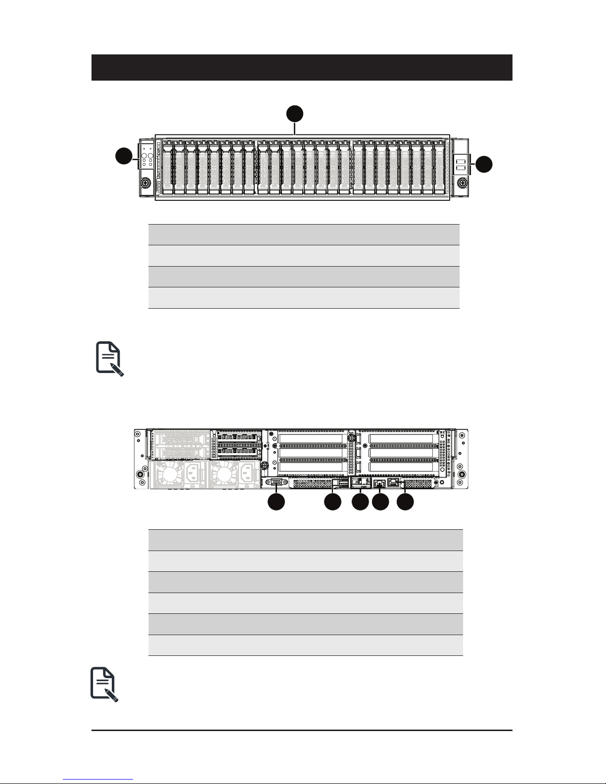
2-1 Front View
No. Description
1.
Front Panel LEDs and buttons
2. HDD Bays
3. Front USB 3.0 ports
• Refer to Chapter
2-3 Front Panel LED
and Buttons for a detailed description of the function
of the LEDs.
2-2 Rear View
No. Description
1. VGA port
2. USB 3.0 ports
3. LAN ports
4. COM port (RJ45 type)
5. 10/100/1000 Server management LAN port
• Refer to Chapter
2-4 Rear System LAN LEDs
for a detailed description of the function of
the LEDs.
1
2
3
2
3
HDD #0
HDD #1
HDD #2
HDD #3
HDD #4
HDD #5
HDD #6
HDD #7
HDD #8
HDD #9
HDD #10
HDD #11
HDD #12
HDD #13
HDD #14
HDD #15
HDD #16
HDD #17
HDD #18
HDD #19
HDD #20
HDD #21
HDD #22
HDD #23
1 2 4 53
Primary
PSU
Secondary
PSU
Rear HDD #0
Rear HDD #1
1 2 4 53
Page 11

System Appearance
- 11 -
2-3 Front Panel LED and Buttons
L1
L2
1
3
5
7
2
4
6
8
No. Name Color Status Description
1.
Reset Button -- -- Press this button to reset the system.
2.
NMI button -- --
Press this button for the server to generate a NMI to the
processor. If multiple-bit ECC errors occur, the server will
effectively be halted.
3.
Power button
with LED
Green On Indicates the system is powered on.
Green Blink System is in ACPI S1 state (sleep mode).
N/A Off
• System is not powered on or in ACPI S5 state (power off)
• System is in ACPI S4 state (hibernate mode)
4.
ID Button
with LED
Blue On Indicates the system identication is active.
N/A Off Indicates the system identication is disabled.
5.
HDD Status
LED
Green
On
Indicates locating the HDD.
Blink
Indicates accessing the HDD.
Amber On
Indicates HDD error.
Green/
Amber
Blink
Indicates HDD rebuilding.
N/A Off
Indicates no HDD access or no HDD error.
6.
System
Status LED
Green On
Indicates system is operating normally.
Amber
On
Indicates a critical condition, may include:
-System fan failure
-System temperature
Blink
Indicates non-critical condition, may include:
-Redundant power module failure
-Temperature and voltage issue
-Chassis intrusion
N/A Off
Indicates system is not ready, may include:
-POST error
-NMI error
-Processor or terminator is missing
Page 12

- 12 -
System Appearance
7.
LAN1 Active/
Link LED
Green On
Indicates a link between the system and the network or
no access.
Green Blink
Indicates data trasmission or receiving is occuring.
N/A Off
Indicates no data transmission or receiving is occuring.
8.
LAN2 Active/
Link LED
Green
On
Indicates a link between the system and the network or
no access.
Green Blink
Indicates data trasmission or receiving is occuring.
N/A Off
Indicates no data transmission or receiving is occuring.
Page 13
System Appearance
- 13 -
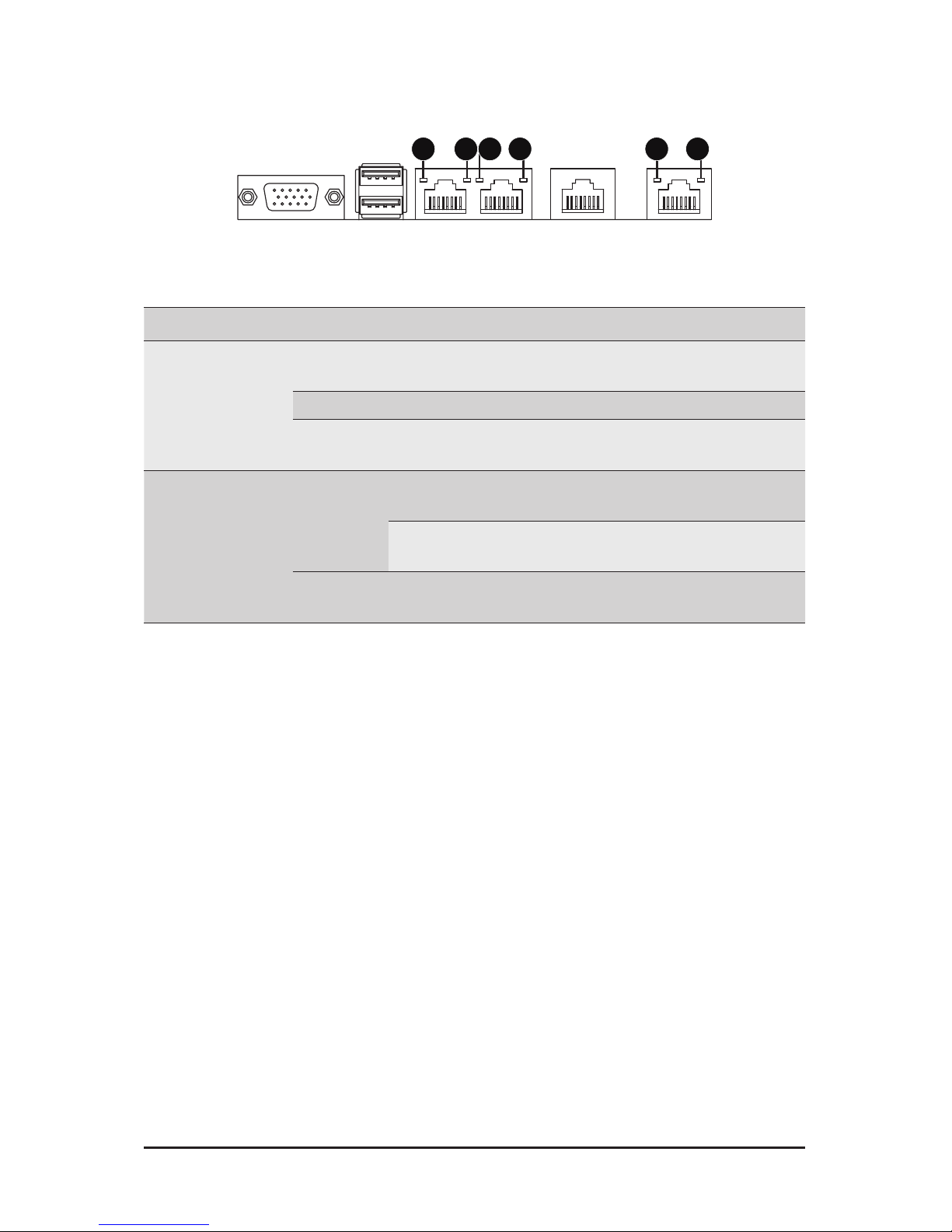
2-4 Rear System LAN LEDs
No. Name Color Status Description
1.
1GbE
Speed LED
Yellow On 1 Gbps data rate
Green On 100 Mbps data rate
N/A Off 10 Mbps data rate
2.
1GbE
Link/
Activity
LED
Green
On Link between system and
network or no access
Blink Data transmission or receiving is occurring
N/A Off No data transmission or
receiving is occurring
1 2 1 221
Page 14
- 14 -
System Appearance
2-5 Hard Disk Drive LEDs
LED#1
LED#2 (Reserved/No Function)
RAID SKU LED #1 Locate HDD
Fault
Rebuilding HDD
Access
HDD Present
(No Access)
No RAID
conguration
(via HBA, ICH)
Disk LED
(LED on
Back Panel)
Green ON(*1) OFF Green OFF
Amber OFF OFF Amber OFF
Removed
HDD Slot
(LED on
Back Panel)
Green ON(*1) OFF Green --
Amber OFF OFF Amber --
RAID
conguration
(via HW RAID
Card, or SW
RAID Card)
Disk LED
Green ON OFF Alternately OFF
Amber OFF ON
(Low Speed:
2 Hz)
OFF
Removed
HDD Slot
Green ON(*1) OFF (*3) --
Amber OFF ON (*3) --
Page 15
System Appearance
- 15 -
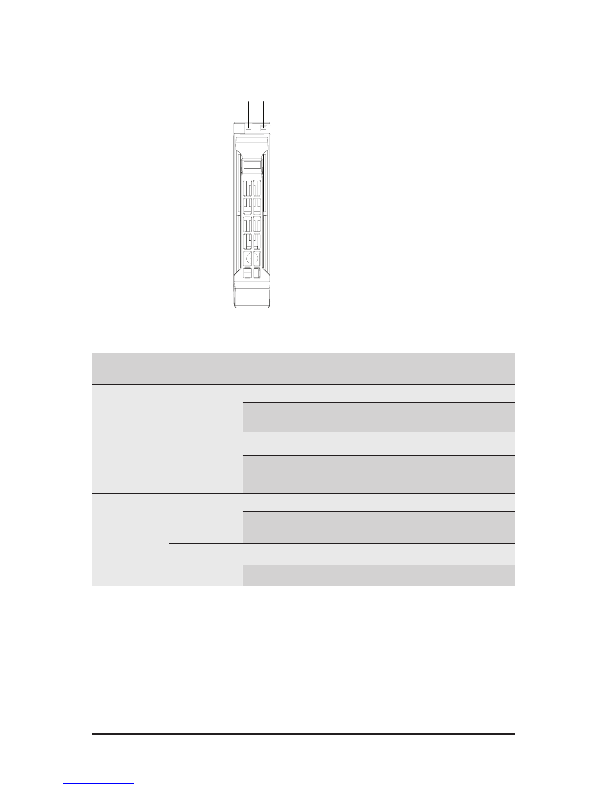
2-6 Power Supply Unit LED
PSU LED
State Description
Green ON Output ON and OK
Off No AC power to all power supplies
Green BLINKING
1 Sec./On
1 Sec./Off
0.5Hz
Standby Mode (normal)
Green BLINKING
0.25 Sec./On
0.25 Sec./Off
2Hz
PSU Sleep Mode (cold Redundant/Ofine mode)
Amber
Standby Mode (with OTP range)
12V Fault (OVP, UVP, OCP, SCP, and OTP)
Power Supply fan lock (15 seconds
including Standby mode)
Amber (*3)
Page 16

- 16 - System Hardware Installation
Pre-installation Instructions
Computer components and electronic circuit boards can be damaged by discharges of static
electricity. Working on computers that are still connected to a power supply can be extremely
dangerous. Follow the simple guidelines below to avoid damage to your computer or injury to
yourself.
• Always disconnect the computer from the power outlet whenever you are working inside the
computer case.
• If possible, wear a grounded wrist strap when you are working inside the computer case.
Alternatively, discharge any static electricity by touching the bare metal system of the computer
case, or the bare metal body of any other grounded appliance.
• Hold electronic circuit boards by the edges only. Do not touch the components on the board
unless it is necessary to do so. Do not ex or stress the circuit board.
• Leave all components inside the static-proof packaging until you are ready to use the component
for the installation.
Chapter 3 System Hardware Installation
Page 17
System Hardware Installation - 17 -
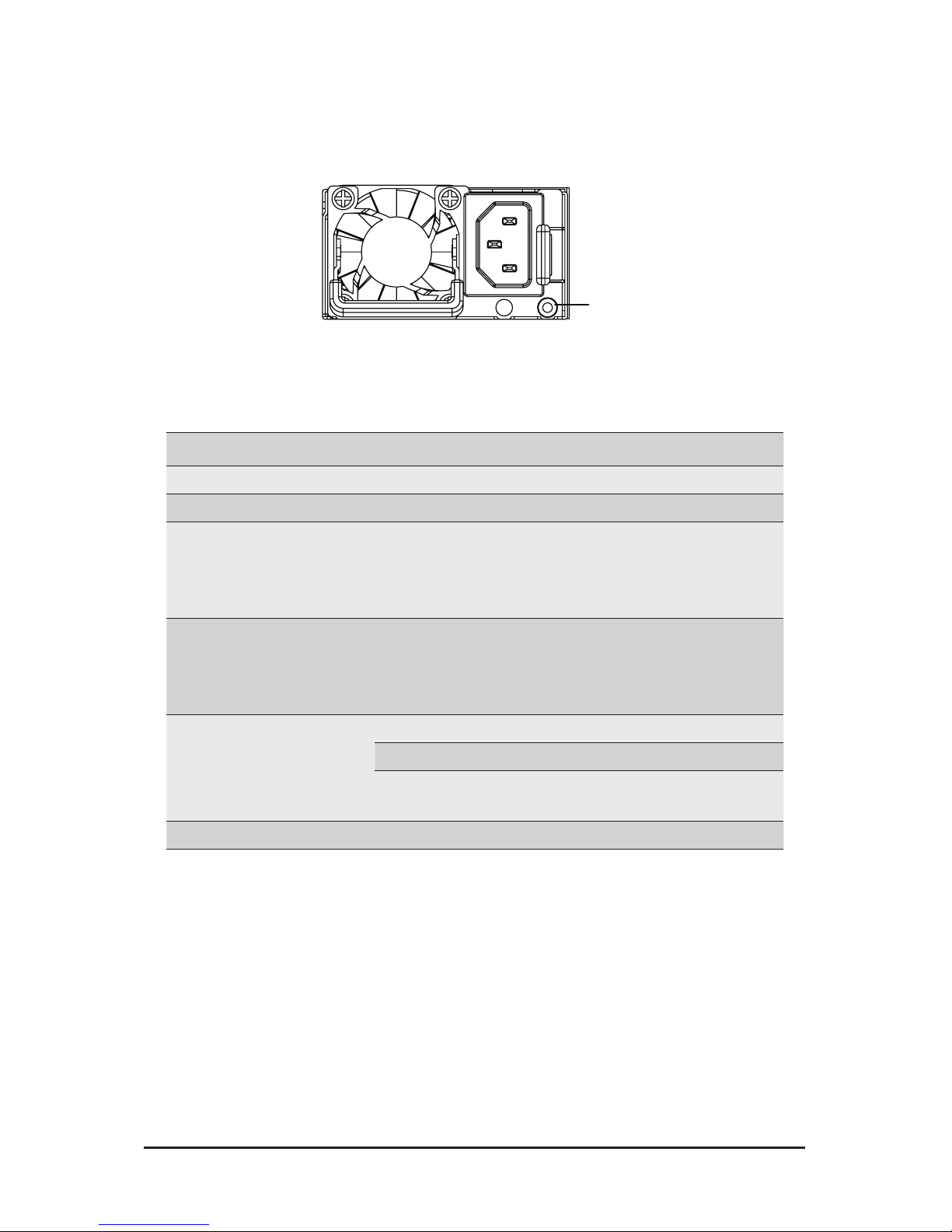
3-1 Removing and Installing the Chassis Cover
Before you remove or install the system cover
• Make sure the system is not turned on or connected to AC power.
Follow these instructions to remove the chassis covers:
1. Loosen and remove the thumbscrew securing the chassis cover.
2. Push down on the indentations located on the side of the chassis cover.
3. Slide the chassis cover to the rear of the system and then remove the cover in the direction of the
arrow.
4. To reinstall the chassis cover follow steps 1-3 in reverse order.
2
1
3
2
2
Page 18
- 16 - System Hardware Installation
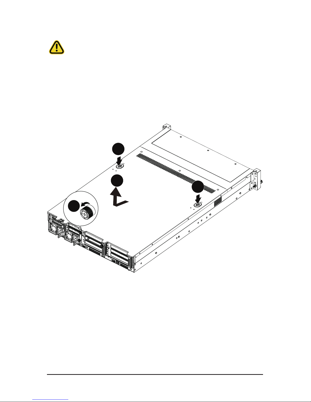
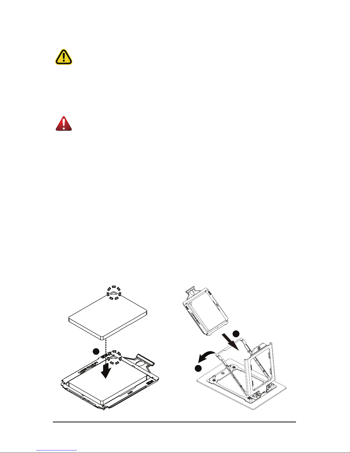
3-2 Removing and Installing the Fan Duct
Follow these instructions to remove the fan duct:
1. Lift up to remove the fan duct.
2. To reinstall the fan duct, align the fan duct with the guiding groove. Push down the fan duct until it is
rmly seated on the system.
Page 19
System Hardware Installation - 19 -
3-3 Removing and Installing the CPU and Heat Sink
Read the following guidelines before you begin to install the CPU:
• Make sure that the motherboard supports the CPU.
• Always turn off the computer and unplug the power cord from the power outlet before installing
the CPU to prevent hardware damage.
• Unplug all cables from the power outlets.
• Disconnect all telecommunication cables from their ports.
• Place the system unit on a at and stable surface.
• Open the system according to the instructions.
WARNING!
Failure to properly turn off the server before you start installing components may cause serious
damage. Do not attempt the procedures described in the following sections unless you are a
qualied service technician.
Follow these instructions to install the CPU:
1. Align and install the processor on the carrier, making sure to line up the triangle markers on the
corner of the CPU to the triangle mark on the corner of the CPU carrier.
2. Slide the carrier assembly into the channels of the carrier bracket
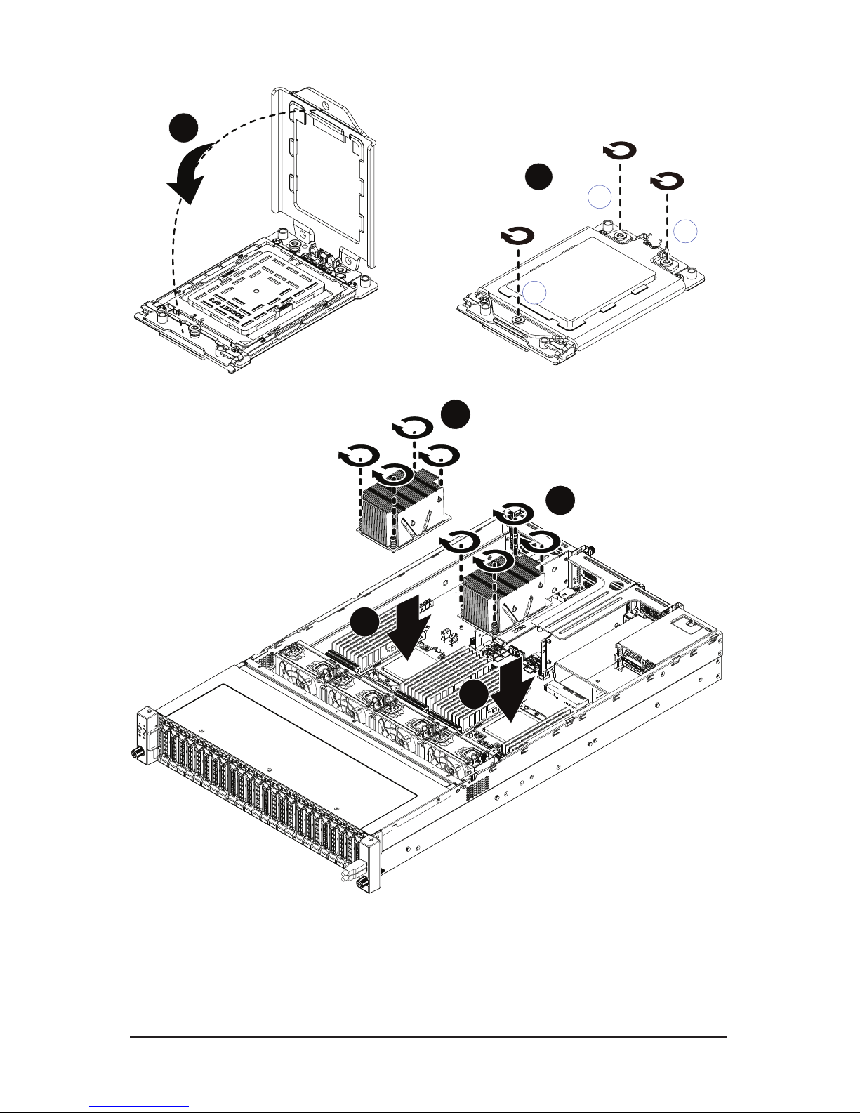
3. Close the carrier bracket so that it rmly latches on to the CPU socket.
4. Close the CPU socket cover.
5. Tighten and secure the CPU socket cover screws in the following order (3g2g1).
NOTE:
When removing the CPU socket cover, loosen the screws in reverse order (1g2g3).
NOTE:
Apply thermal compound evenly on the top of the CPU. Remove the protective cover from
the underside of the heat sink.
6. Align and place the heatsink onto the top of the CPU socket.
7. To secure the heatsink, tighten the four screws to the CPU socket.
8. Repeat steps 1-7 for the second CPU and heatsink.
9. To remove the heatsinks and CPUs, follow steps 1-7 in reverse order.
1
2
3
Page 20
- 16 - System Hardware Installation
6
6
7
7
4
1
3
2
5
Page 21
System Hardware Installation - 21 -
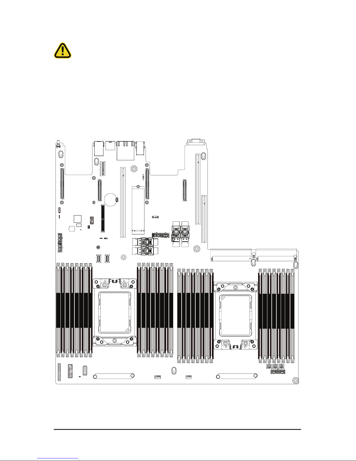
3-4 Removing and Installing Memory
3-4-1 Eight-Channel Memory Conguration
This motherboard provides 32 DDR4 memory sockets and supports Eight Channel Technology. After the
memory is installed, the BIOS will automatically detect the specications and capacity of the memory.
21
&38
3ULPDU\
CPU1
(Secondary)
DIMM_P0_H1
DIMM_P0_H0
DIMM_P0_G1
DIMM_P0_G0
DIMM_P0_F1
DIMM_P0_F0
DIMM_P0_E1
DIMM_P0_E0
DIMM_P0_A0
DIMM_P0_A1
DIMM_P0_B0
DIMM_P0_B1
DIMM_P0_C0
DIMM_P0_C1
DIMM_P0_D0
DIMM_P0_D1
DIMM_P1_N0
DIMM_P1_N1
DIMM_P1_M0
DIMM_P1_M1
DIMM_P1_O0
DIMM_P1_O1
DIMM_P1_P0
DIMM_P1_P1
DIMM_P1_K1
DIMM_P1_K0
DIMM_P1_L1
DIMM_P1_L0
DIMM_P1_J1
DIMM_P1_J0
DIMM_P1_I1
DIMM_P1_I0
Read the following guidelines before you begin to install the memory:
• Make sure that the motherboard supports the memory. It is recommended that memory of the
same capacity, brand, speed, and chips be used.
• Always turn off the computer and unplug the power cord from the power outlet before installing
the memory to prevent hardware damage.
• Memory modules have a foolproof design. A memory module can be installed in only one
direction. If you are unable to insert the memory, switch the direction.
Page 22
- 16 - System Hardware Installation
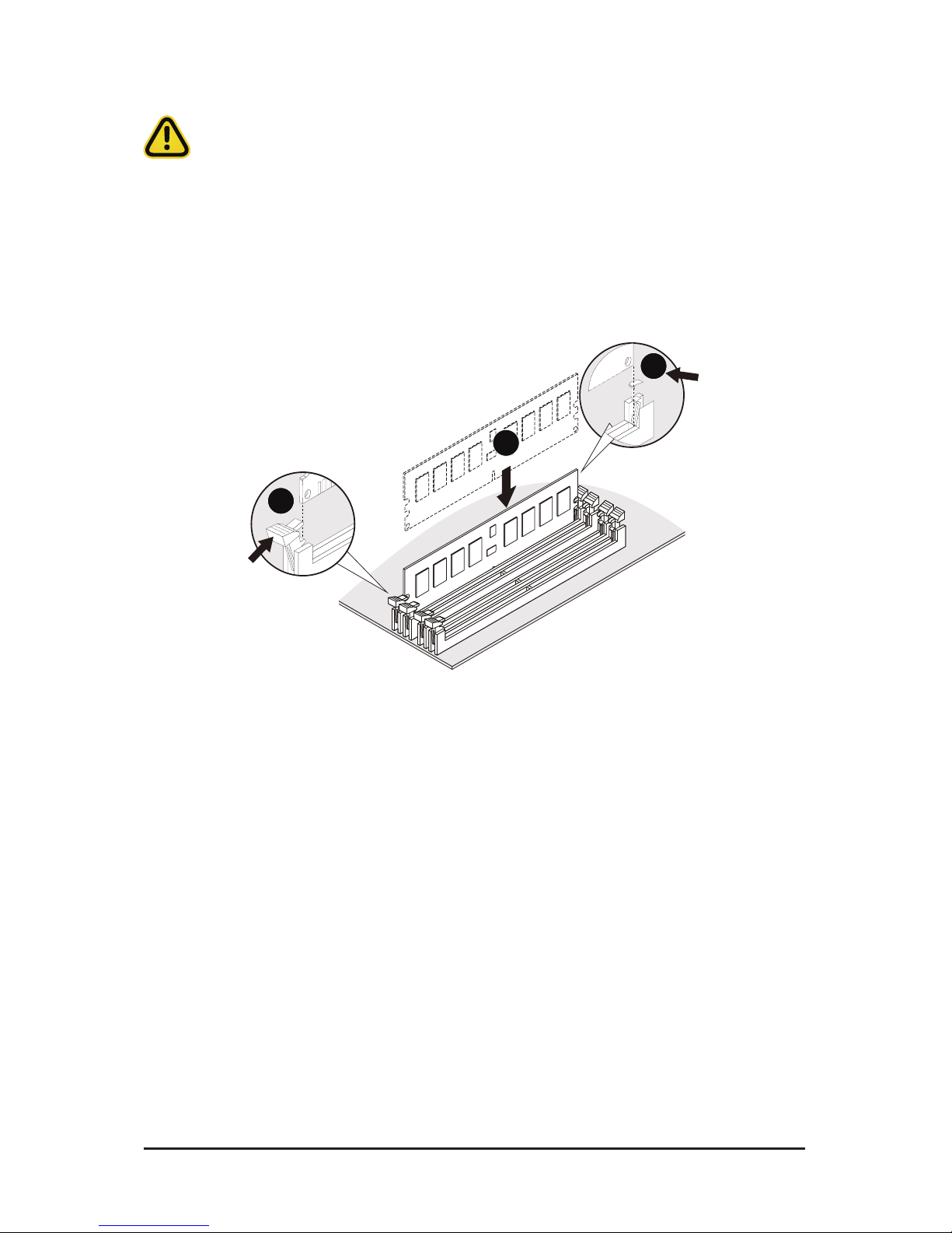
3-4-2 Removing and Installing a Memory Module
Before installing a memory module, make sure to turn off the computer and unplug the power
cord from the power outlet to prevent damage to the memory module.
Be sure to install DDR4 DIMMs on to this motherboard.
Follow these instructions to install a DIMM module:
1. Insert the DIMM memory module vertically into the DIMM slot and push it down.
2. Close the plastic clip at both edges of the DIMM slots to lock the DIMM module.
3. Reverse the installation steps when you want to remove the DIMM module.
1
2
2
Page 23
- 16 - System Hardware Installation
3-4-3 DIMM Population Table
DIMM
DIMMs
Populated
1R
-- --
--
2--
--
-- --
--
--
--
--
2667
2400
Not Supported
2133
2133
2133
1
1
2
1
1
1
-- --
--
--
Not Supported
Not Supported
Not Supported
1
11
1
2
4DR1.2V
2R
2DR
2S2R
2S4R
Frequency (MT/s)
2
1
RDIMM Maximum Frequency Supported Table
LRDIMM Maximum Frequency Supported Table
Population Table
DIMMs
Populated
DIMM
1R
2
1
-- --
2 --
1
--
--
-- --
-- Not Supported
2667
2667
Not Supported
Not Supported
2133
1
1
--
--2
1
1
--
-- --
--
--
2133
Not Supported
2133
1
11
1
2
4DR
1.2V
2S4R
Frequency (MT/s)
DIMMs
Populated
DIMM0DIMM1
-- 11
11
2
Page 24
System Hardware Installation - 24 -
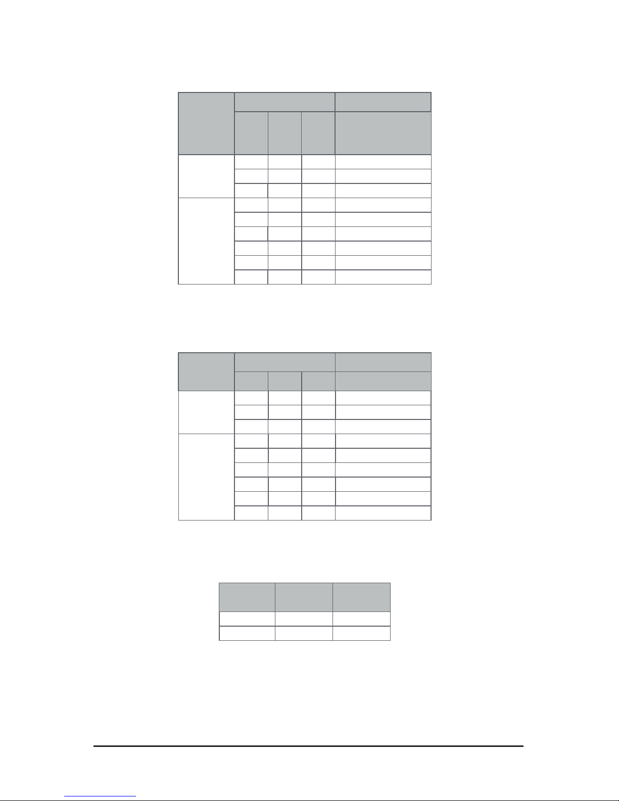
3-5 Removing and Installing the PCI Expansion Card
• Voltages can be present within the server whenever an AC power source is connected. This
voltage is present even when the main power switch is in the off position. Ensure that the system
is powered off and all power sources have been disconnected from the server prior to installing a
PCIe card.
• Failure to observe these warnings could result in personal injury or damage to equipment.
• The PCI riser assembly does not include a riser card or any cabling as standard. To install a
PCIe card, a riser card must be installed.
Follow these instructions to PCI Expansion card:
1. Loosen and remove the thumbscrew on the riser bracket.
2. Remove the screw securing the riser bracket.
3. Lift up the riser bracket out of system.
4. Loosen and remove the screw securing the slot cover from riser bracket.
5. Orient the PCIe card with the riser guide slot and push in the direction of the arrow until the PCIe
card sits in the PCIe card connector.
NOTE:
Some riser brackets allow for single or multiple PCIe cards. Repeat steps 4-5 as necessary.
6. Secure the PCIe card with the screw.
7. Reverse steps 1-3 to install the riser bracket.
2
3
4
5
6
5
5
6
6
4
4
1
Page 25
- 16 - System Hardware Installation
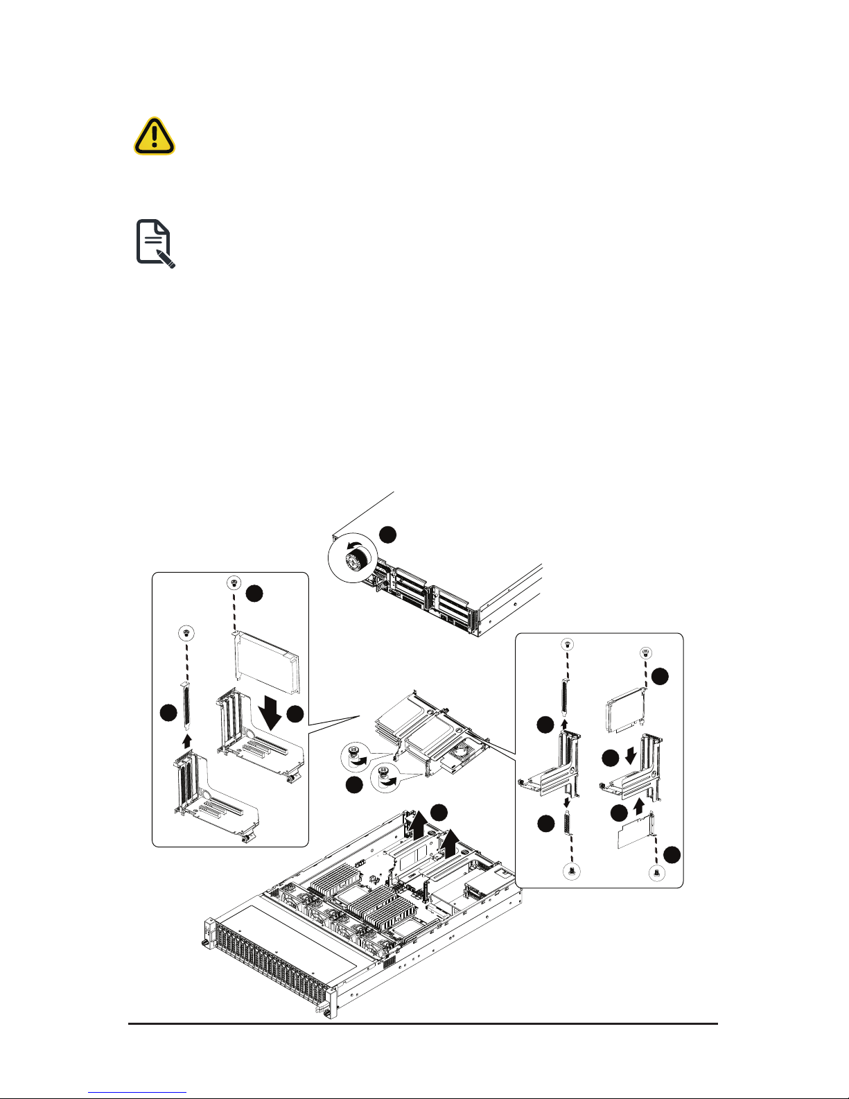
3-6 Removing and Installing the Hard Disk Drive
Read the following guidelines before you begin to install the hard disk drive:
• Take note of the drive tray orientation before sliding it out.
• The tray will not t back into the bay if it is inserted incorrectly.
• Make sure that the HDD is connected to the HDD connector on the backplane.
Follow these instructions to install a hard disk drive:
1. Press the release button.
2. Extend the locking lever.
3. Pull the locking lever in the direction of the arrow to remove the HDD tray.
4. Slide the hard disk into the HDD tray.
5. Install 4 screws to secure the hard drive to the HDD tray.
6. Reinsert the HDD tray into the slot and close the locking lever.
1
3
2
4
5
5
Page 26
System Hardware Installation - 26 -
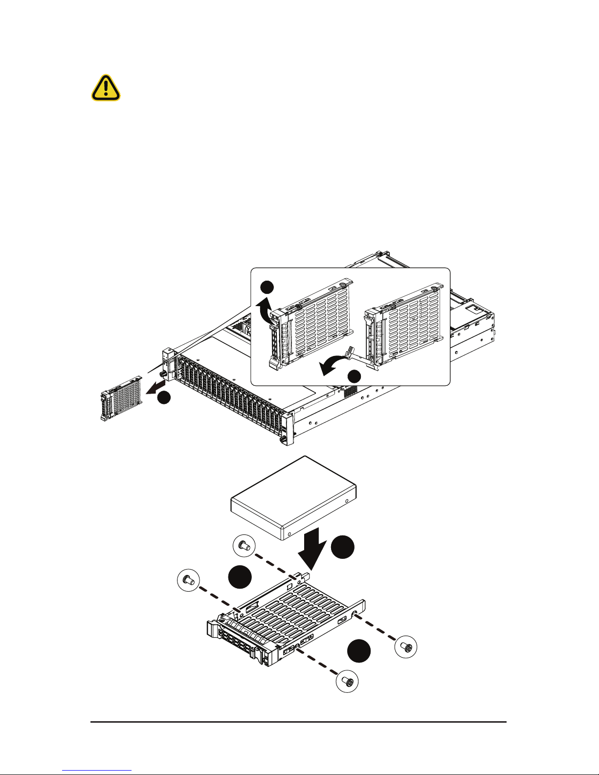
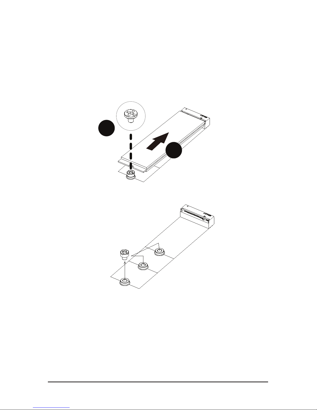
3-7 Installing and Removing an M.2 Solid State Drive
Follow these instructions to install an optional M.2 solid state drive (SSD):
1. Place the solid state drive into the M.2 connector.
2. Secure the solid state drive to the motherboard with a single screw.
NOTE:
The position of the screw will depend on the size of the SSD. Refer to the second image
below for proper placement.
3. Reverse steps 1-2 to remove the solid state drive.
2
1
2260
2240
2280
1
Page 27
- 16 - System Hardware Installation
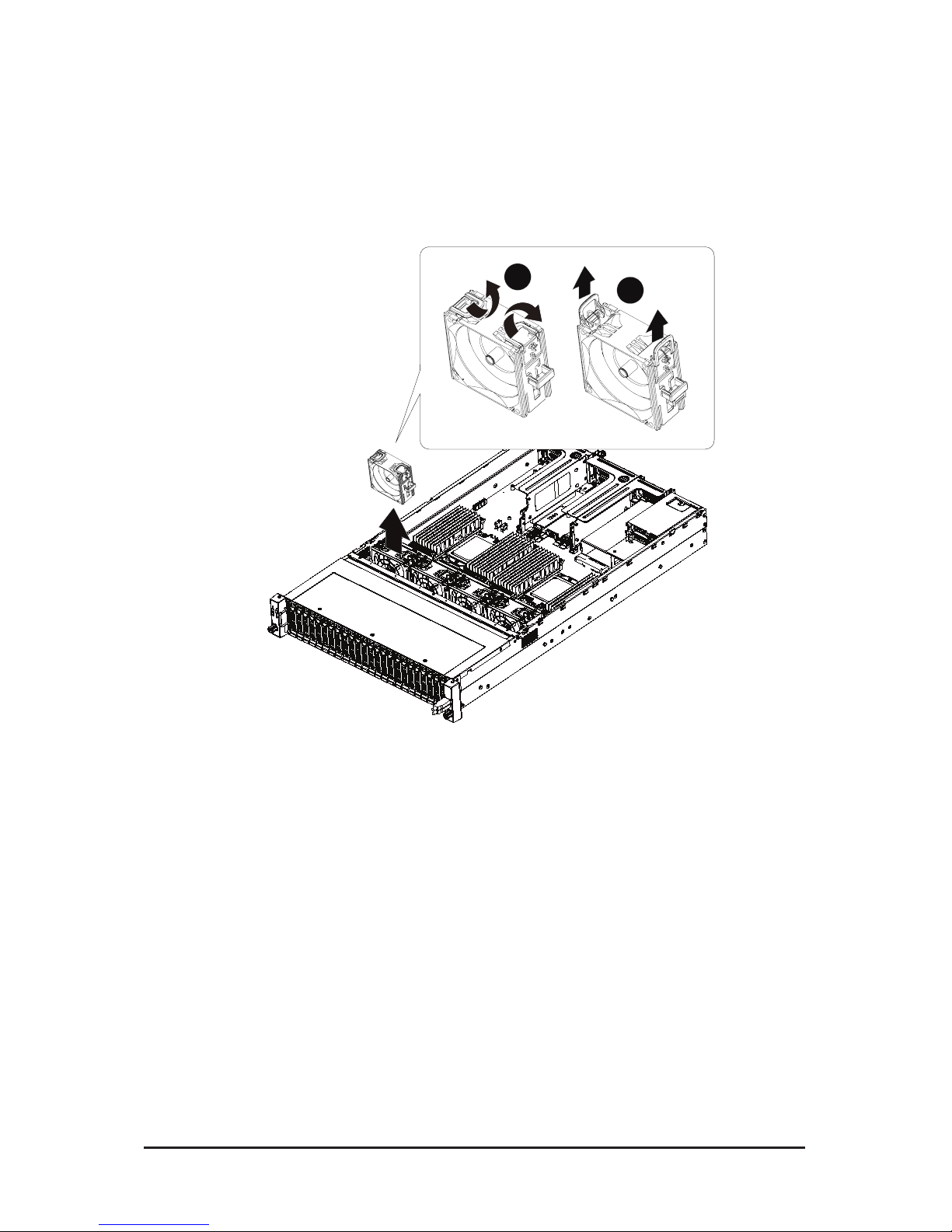
3-8 Replacing the Fan Assembly
Follow these instructions to replace a fan assembly:
1. Flip the latches on the top of the fan outwards.
2. Using the latches, lift up the fan assembly from the chassis.
3. Reverse the previous steps to install the replacement fan assembly.
1
2
Page 28

System Hardware Installation - 28 -
3-9 Removing and Installing the Power Supply
Follow these instructions to replace the power supply:
1. Press the retaining clip on the left side of the power supply unit along the direction of the arrow.
2. Pull the power supply handle at the same time and pull out the power supply unit.
3. Insert the replacement power supply unit rmly into the chassis. Connect the AC power cord to the
replacement power supply.
4. Repeat steps 1-3 for replacement of the second power supply.
1
2
3
Before you remove or install the power supply unit:
• Make sure the system is not turned on or connected to AC power.
Page 29
- 16 - System Hardware Installation
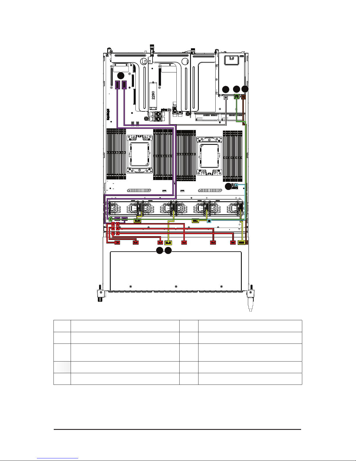
3-10 Cable Routing (1 of 2)
No. Cable No. Cable
1. OCP RAID Card to SAS EXP Card (Purple) 2. Rear Back Plane/ B Power Cable (Grey)
3.
SAS EXP to Rear Back Plane/B Cable
(Green)
4. Rear Back Plane/B Signal Cable (Brown)
5. NVME Card Power Cable (Light Blue) 6. SAS EXP to Back Plane/B Cable (Red)
7. System Fan Power Aable (Yellow)
3
2
1
4
5
7
6
Page 30
System Hardware Installation - 30 -
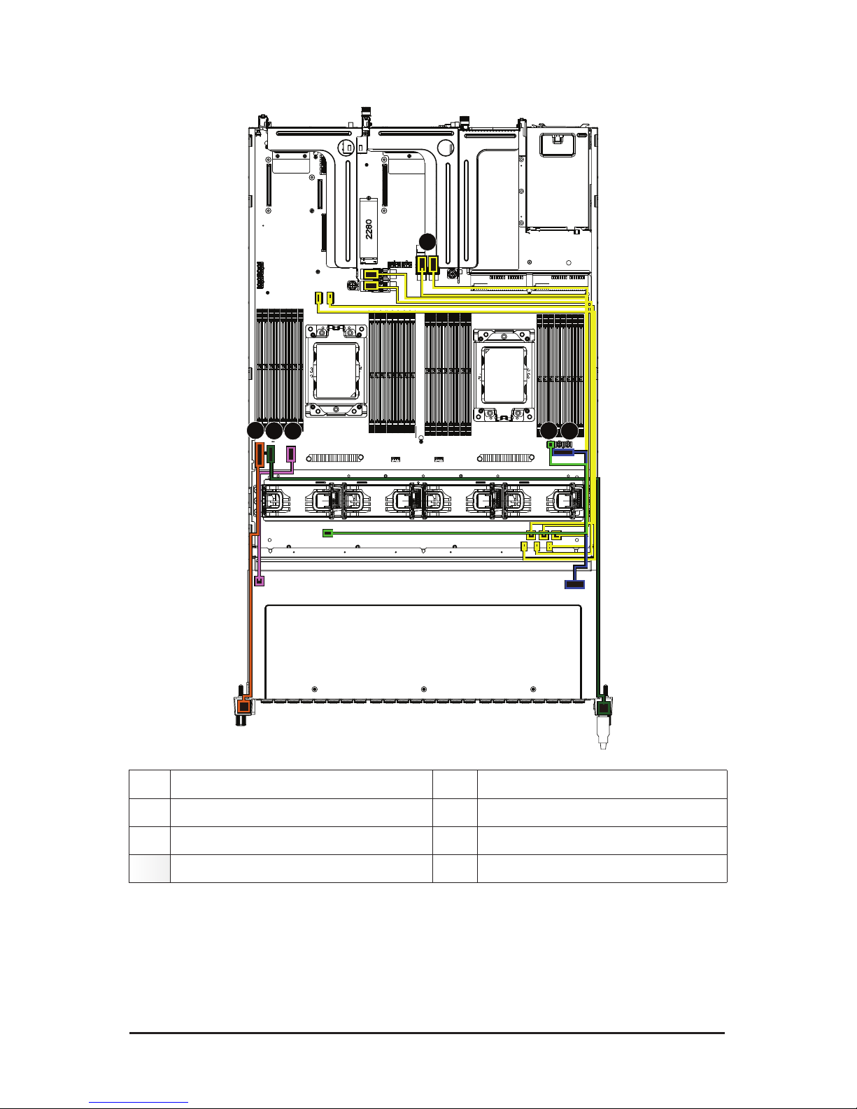
3-11 Cable Routing (2 of 2)
No. Cable No. Cable
8. NVME Cable (Yellow) 9. Front Plane/B cable (Dark Orange)
10. Front USB Cable (Dark Green) 11. Back Plane/B Signal Cable (Pink)
12. SAS EXP Power Cable (Light Green) 13. Back Plane/B PW Cable(Dark Blue)
8
9
10
12
11
13
Page 31

- 37 -
Motherboard Components
Chapter 4 Motherboard Components
4-1 Motherboard Components
21
1
3
2
4
8
6
5
7
9
9
11
10
12
13
14
16
15
1817
19 20
21
21
22
22
23 24
255
26
&38
3ULPDU\
CPU1
(Secondary)
DIMM_P0_H1
DIMM_P0_H0
DIMM_P0_G1
DIMM_P0_G0
DIMM_P0_F1
DIMM_P0_F0
DIMM_P0_E1
DIMM_P0_E0
DIMM_P0_A0
DIMM_P0_A1
DIMM_P0_B0
DIMM_P0_B1
DIMM_P0_C0
DIMM_P0_C1
DIMM_P0_D0
DIMM_P0_D1
DIMM_P1_N0
DIMM_P1_N1
DIMM_P1_M0
DIMM_P1_M1
DIMM_P1_O0
DIMM_P1_O1
DIMM_P1_P0
DIMM_P1_P1
DIMM_P1_K1
DIMM_P1_K0
DIMM_P1_L1
DIMM_P1_L0
DIMM_P1_J1
DIMM_P1_J0
DIMM_P1_I1
DIMM_P1_I0
Item Description
1 HDD back plane board connector
2 Case open intrusion header
3 Front panel USB 3.0 connector)
4 Front panel connector
5 2 x 4 Pin GPGPU power connectors
6 BMC rmware readiness LED
7 TPM modue connector
8 IPMB connector
9 OCP mezzanine connector#1
Page 32

Motherboard Components
- 38 -
10 Riser slot connector #1
11 SGPIO connector
12 M.2 slot (PCIe Gen3 x4, Support NGFF-2280, M-Key)
13 Slimline SAS connector #0 (PCIe/SATA/Congurable and dene SKUs)
14 Slimline SAS connector #1 (PCIe/SATA/Congurable and dene SKUs)
15 Slimline SAS connector #3 (PCIe/SATA/Congurable and dene SKUs)
16 Slimline SAS connector #2 (PCIe/SATA/Congurable and dene SKUs)
17 2 x 4 Pin GPGPU power connector
18 2 x 3 Pin Rear back plane board power connector
19 Slimline SAS connector #4 (PCIe/SATA/Congurable and dene SKUs)
20 Slimline SAS connector #5 (PCIe/SATA/Congurable and dene SKUs)
21* OCP mezzanine connector#2 (Support NCSI)
22 Riser slot connector #2
23 Power supply connector#1 (primary)
24 Power supply connector#2 (secondary)
25 2 x 2 Pin extention card power connectors
26 2 x 7 Pin system main power connector
NOTE! Set the NCSI switch to On to enable NCSI fucnction.
Page 33

- 39 -
Motherboard Components
4-2 Jumper Settings
21
&38
3ULPDU\
CPU1
(Secondary)
HOST_SMBUS_SEL
PMBUS_SEL
ON
CPLD debug mode Normal [Default]
Normal [Default]
BIOS defined
BIOS defined
Clear supervisor password
OFF
BIOS_PWD
DB_PLD
J1
1
2
3
4
21',3
-
NCSI Switch
21
Onboard LAN
OCP MEZZ
ON
OFF
目目
Chapter 4 Mothe r board
Components 36
4-3 Motherboard Components
36
4-4 Jumper Settings 38
Page 34

Motherboard Components
- 40 -
Page 35

- 41 - BIOS Setup
BIOS (Basic Input and Output System) records hardware parameters of the system in the EFI on the
motherboard. Its major functions include conducting the Power-On Self-Test (POST) during system startup,
saving system parameters and loading operating system, etc. BIOS includes a BIOS Setup program that
allows the user to modify basic system conguration settings or to activate certain system features. When the
power is turned off, the battery on the motherboard supplies the necessary power to the CMOS to keep the
conguration values in the CMOS.
To access the BIOS Setup program, press the <F2> key during the POST when the power is turned on.
Chapter 1 BIOS Setup
• BIOS ashing is potentially risky, if you do not encounter problems of using the current BIOS
version, it is recommended that you don't ash the BIOS. To ash the BIOS, do it with caution.
Inadequate BIOS ashing may result in system malfunction.
• It is recommended that you not alter the default settings (unless you need to) to prevent system
instability or other unexpected results. Inadequately altering the settings may result in system's
failure to boot. If this occurs, try to clear the CMOS values and reset the board to default values.
(Refer to the Exit section in this chapter or introductions of the battery/clearing CMOS jumper in
Chapter 1 for how to clear the CMOS values.)
BIOS Setup Program Function Keys
<f><g> Move the selection bar to select the screen
<h><i> Move the selection bar to select an item
<+> Increase the numeric value or make changes
<-> Decrease the numeric value or make changes
<Enter> Execute command or enter the submenu
<Esc> Main Menu: Exit the BIOS Setup program
Submenus: Exit current submenu
<F1> Show descriptions of general help
<F3> Restore the previous BIOS settings for the current submenus
<F9> Load the Optimized BIOS default settings for the current submenus
<F10> Save all the changes and exit the BIOS Setup program
Page 36

BIOS Setup - 42 -
Main
This setup page includes all the items in standard compatible BIOS.
Advanced
This setup page includes all the items of AMI BIOS special enhanced features.
(ex: Auto detect fan and temperature status, automatically congure hard disk parameters.)
AMD CBS
This setup page includes the common items for conguration of AMD motherboard-related information.
Chipset
This setup page includes all the submenu options for conguring the function of processor, network,
North Bridge, South Bridge, and System event logs.
Server Management
Server additional features enabled/disabled setup menus.
Security
Change, set, or disable supervisor and user password. Conguration supervisor password allows you to
restrict access to the system and BIOS Setup.
A supervisor password allows you to make changes in BIOS Setup.
A user password only allows you to view the BIOS settings but not to make changes.
Boot
This setup page provides items for conguration of boot sequence.
Save & Exit
Save all the changes made in the BIOS Setup program to the CMOS and exit BIOS Setup. (Pressing
<F10> can also carry out this task.)
Abandon all changes and the previous settings remain in effect. Pressing <Y> to the confirmation
message will exit BIOS Setup. (Pressing <Esc> can also carry out this task.)
Page 37

- 43 - BIOS Setup
5-1 The Main Menu
Once you enter the BIOS Setup program, the Main Menu (as shown below) appears on the screen. Use
arrow keys to move among the items and press <Enter> to accept or enter other sub-menu.
Main Menu Help
The on-screen description of a highlighted setup option is displayed on the bottom line of the Main Menu.
Submenu Help
While in a submenu, press <F1> to display a help screen (General Help) of function keys available for the
menu. Press <Esc> to exit the help screen. Help for each item is in the Item Help block on the right side of
the submenu.
• When the system is not stable as usual, select the Restore Defaults item to set your system
to its defaults.
• The BIOS Setup menus described in this chapter are for reference only and may differ by
BIOS version.
Project Name
Displays the project name information.
Project Version
Displays version number of the BIOS setup utility.
Build Date and Time
Displays the date and time when the BIOS setup utility was created.
BMC Information
(Note)
BMC Firmware Version
(Note)
Displays BMC rmware version information.
Onboard LAN Information
LAN1 MAC Address
(Note)
Displays LAN1 MAC address information.
LAN2 MAC Address
(Note)
Displays LAN2 MAC address information.
Page 38

BIOS Setup - 44 -
Total Memory
(Note)
Displays the information for the installed memory size.
Memory Speed
(Note)
Displays the information for the installed memory speed.
System Date
Sets the date following the weekday-month-day-year format.
System Time
Sets the system time following the hour-minute-second format.
(Note) Functions available on selected models.
Page 39

- 45 - BIOS Setup
5-2 Advanced Menu
The Advanced menu display submenu options for conguring the function of various hardware components.
Select a submenu item, then press [Enter] to access the related submenu screen.
Page 40

BIOS Setup - 46 -
5-2-1 iSCSI Conguration
iSCSI Initiator Name
Add an Attempt
Press [Enter] for conguration of advanced items.
Delete Attempts
Press [Enter] for conguration of advanced items.
Change Attempt Order
Press [Enter] for conguration of advanced items.
Page 41

- 47 - BIOS Setup
5-2-2 QLogic 577xx/578xx 10 Gb Ethernet BCM57810
Main Conguration Page
Firmware Image Menu
Press [Enter] to view device rmware version information.
Device Hardware Conguration Menu
Press [Enter] to congure device and port specic parameters.
MBA Conguration Menu
Press [Enter] to congure Multiple Boot Agent (MBA) parameters.
iSCSI Boot Conguration Menu
Press [Enter] to congure iSCSI boot parameters.
Page 42

BIOS Setup - 48 -
Multi-Function Mode
Virtualization mode conguration. System must be rebooted in order for changes to take effect.
Options available: SF/SR-IOV. Default setting is SF.
Blink LEDs
Blink LEDs for a duration up to 15 seconds.
Default setting is 0.
Chip Type
Displays the chip type.
PCI Device ID
Displays the PCI device ID.
Bus: Device: Function
Displays the bus number, device number, and function number.
Link Status
Displays the link status.
Parameter MAC Address
Displays the Permanent MAC Address.
Virtual MAC Address
Displays the Virtual MAC Address.
Page 43

- 49 - BIOS Setup
5-2-2-1 Firmware Image Menu
Main Conguration Page > Firmware Image Menu
Displays the device's rmware version information.
Page 44

BIOS Setup - 50 -
5-2-2-2 Device Hardware Conguration Menu
Main Conguration Page > Device Hardware Conguration Menu
Congures the device and port specic parameters. Please refer to help text dened per congurable
parameter for more information.
DCB Protocol
Enable/Disable the DCB Protocol.
Options available: Enabled/Disabled. Default setting is Enabled.
Number of VFs per PF
Displays the number of VFs per PF in multiple of 8 (0 to 64).
Max PF MSI-X Vectors
Displays the maximum number of PF MSI-X Vectors. (0 to 64).
UEFI Boot Mode
Species Driver Boot Mode in UEFI environment.
Default setting is UNDI.
MFW Crash Dump Feature
Enables MFW bootcode to collect critical device and system information during unanticipated system
crash.
Options available: Enabled/Disabled. Default setting is Enabled.
Page 45

- 51 - BIOS Setup
5-2-2-3 MBA Conguration Menu
Main Conguration Page > MBA Conguration Menu
Congures the Multiple Boot Agent (MBA) parameters.
QLogic 577xx/578xx 10 Gb Ethernet BCN57810
Legacy Boot Protocol
Selects a non-UEFI Boot Protocol to be used.
Options available: PXE/iSCSI/None. Default setting is None.
Page 46

BIOS Setup - 52 -
Boot Strap Type
Selects the BIOS interrupt call type.
Auto Detect: Auto Detect interrupt type; BBS: BIOS Boot Specification; Int 18h: Interrupt vector to
execute cassette BASIC; Int 19h: BIOS Interrupt vector used to load OS.
Options available: Auto Detect/BBS/Int 18h/Int 19h. Default setting is Auto Detect.
Hide Setup Prompt
Congures whether Setup Prompt is displayed during ROM initialization.
Options available: Enabled/Disabled. Default setting is Disabled.
Setup Key Stroke
Congure key strokes to invoke conguration menu.
Options available: Ctrl-S/Ctrl-B. Default setting is Ctrl-S.
Banner Message Timeout
Selects the timeout value. (0 defaults to 4 seconds, 15 is no delay, 1-14 is timeout value in seconds).
Default setting is 5.
Link Speed
Congures the link speed.
Default setting is 10 Gbps Full.
Wake On LAN
Congures Wake on LAN (WOL). This setting is per port.
Options available: Enabled/Disabled. Default setting is Disabled.
VLAN Mode
Congures the virtual LAN mode.
Options available: Enabled/Disabled. Default setting is Disabled.
VLAN ID (1..4094)
Displays the virtual LAN ID (1 to 4094).
Boot Retry Count
Selects the number of boot retries.
Options available: No Retry/1 Retry/2 Retries/3 Retries/4 Retries/5 Retries/6 Retries/Indenite Retries.
Default setting is No Retry.
Page 47

- 53 - BIOS Setup
5-2-2-4 iSCSI Boot Conguration Menu
Main Conguration Page > iSCSI Boot Conguration Menu
Congures the iSCSI boot parameters.
iSCSI General Parameters
Press [Enter] for conguration of advanced items.
iSCSI Initiator Parameters
Press [Enter] for conguration of advanced items.
iSCSI First Target Parameters
Press [Enter] for conguration of advanced items.
iSCSI Second Target Parameters
Press [Enter] for conguration of advanced items.
Page 48

BIOS Setup - 54 -
5-2-2-4-1 iSCSI General Parameters
Main Conguration Page > iSCSI Boot Conguration Menu > iSCSI General
Parameters
Congures the iSCSI general boot parameters.
TCP/IP Parameters via DHCP
Acquires the TCP/IP conguration via DHCP.
Options available: Enabled/Disabled. Default setting is Enabled.
IP Autoconguration
Auto-congures the IP conguration.
Options available: Enabled/Disabled. Default setting is Disabled.
Please note that this item is congurable when TCP/IP Parameters via DHCP is set to Disabled.
Page 49

- 55 - BIOS Setup
iSCSI Parameters via DHCP
Acquires the iSCSI parameters via DHCP.
Options available: Enabled/Disabled. Default setting is Enabled.
CHAP Authentication
Enable/Disable the CHAP authentication.
Options available: Enabled/Disabled. Default setting is Disabled.
Boot to Target
Enable/Disable booting to iSCSI target after log-on.
Options available: Disabled/Enabled/One Time Disabled. Default setting is Enabled.
DHCP Vendor ID
Press [Enter] to congures the DHCP vendor ID (up to 32 bytes long).
Link Up Delay Time
Congures the link up to delay time in seconds (0..225).
Use TCP Timestamp
Enable/Disable the TCP timestamp.
Options available: Enabled/Disabled. Default setting is Disabled.
Target as rst HDD
Enable/Disable target appears as a rst hard disk drive (HDD) in the system.
Options available: Enabled/Disabled. Default setting is Disabled.
LUN Busy Retry Count
Congures the number of retries in 2 second intervals when LUN is busy (0..60).
Default setting is 0.
IP Version
Displays the IP version supported. Modifying this parameter will reset all IP-related elds.
Page 50

BIOS Setup - 56 -
5-2-2-4-2 iSCSI Initiator Parameters
Main Conguration Page > iSCSI Boot Conguration Menu > iSCSI Initiator
Parameters
Congures the iSCSI initiator parameters.
IP Address
Congures initiator IP address.
Subnet Mask
Congures IP subnet mask.
Default Gateway
Congures default gateway IP address.
Page 51

- 57 - BIOS Setup
Primary DNS
Congures the primary DNS IP address.
Secondary DNS
Congures the second DNS IP address.
iSCSI Name
Congures the iSCSI name.
CHAP ID
Configures the Challenge-Handshake Authentication Protocol (CHAP) ID (up to 128 characters in
length).
CHAP Secret
Configure the Challenge-Handshake Authentication Protocol (CHAP) Secret (12 to 16 characters in
length).
Page 52

BIOS Setup - 58 -
5-2-2-4-3 iSCSI First Target/Second Target Parameters
Main Conguration Page > iSCSI Boot Conguration Menu > iSCSI First Target/
Second Target arameters
Congures the iSCSI rst target parameters.
Connect
Enable/Disable the target establishment.
Options available: Enabled/Disabled. Default setting is Disabled.
IP Address
Congures the target IP address.
Page 53

- 59 - BIOS Setup
TCP Port
Congures the target TCP port number (13365535).
Boot LUN
Congure the target boot LUN number (0..255).
iSCSI Name
Congures the iSCSI name.
CHAP ID
Configures the Challenge-Handshake Authentication Protocol (CHAP) ID (up to 128 characters in
length).
CHAP Secret
Configure the Challenge-Handshake Authentication Protocol (CHAP) Secret (12 to 16 characters in
length).
Page 54

BIOS Setup - 60 -
5-2-3 VLAN Conguration
Enter Conguration Menu
Press [Enter] to enter conguration menu for VLAN conguration.
Page 55

- 61 - BIOS Setup
5-2-3-1 VLAN Conguration Menu
Create new VLAN
VLAN ID
Sets a VLAN ID of new VLAN or existing VLAN, valid value is 0 to 4094.
Priority
Sets the 802.1Q Priority, valid value is 0 to 7.
Add VLAN
Creates a new VLAN or update existing VLAN.
Congured VLAN List
Displays the congured VLAN list information.
Options available: Enabled/Disabled. Default setting is Disabled.
Remove VLAN
(Note)
Removes the selected VLANs.
Please note that this item is only executable when Congured VLAN List is set to Enabled, and
once executed the Congured VLAN List will be updated accordingly.
(Note) Only Supported when Congured VLAN List is set to Enabled.
Page 56

BIOS Setup - 62 -
5-2-4 CPU Conguration
CPU Conguration
SVM Mode
Enable/disable the CPU Virtualization.
Options available: Enabled/Disabled. Default setting is Enabled.
SMEE
Controls the Secure Memory Encryption Enable (SMEE) function.
Options available: Enabled/Disabled. Default setting is Enabled.
CPU 0 Information
Press [Enter] to view the memory information related to CPU 0.
Page 57

- 63 - BIOS Setup
5-2-4-1 CPU 0 Information
Page 58

BIOS Setup - 64 -
5-2-5 SATA Conguration
Page 59

- 65 - BIOS Setup
5-2-6 USB Conguration
USB Conguration
USB Controllers:
Displays the supported USB controllers.
USB Devices:
Displays the USB devices connected to the system.
Legacy USB Support
Enable/disable the Legacy USB support fuction. AUTO option disables legacy support if no USB devices
are connected. DISABLE option will keep USB devices available only for EFI applications.
Options available: Enabled/Disabled/Auto. Default setting is Enabled.
XHCI Hand-off
This is a workaround for OSes without XHCI hand-off support. The XHCI ownership change should be
claimed by XHCI driver.
Options available: Enabled/Disabled. Default setting is Enabled.
USB Mass Storage Driver Support
(Note)
Enable/Disable the USB Mass Storage Driver Support.
Options available: Enabled/Disabled. Default setting is Enabled.
Port 60/64 Emulation
Enables the I/O port 60h/64h emulation support. This should be enabled for the complete USB Keyboard
Legacy support for non-USB aware OSes.
Options available: Enabled/Disabled. Default setting is Enabled.
USB hardware delays and time-outs:
USB transfer time-out
The time-out value for Control, Bulk, and Interrupt transfers.
Options available: 1 sec/5 sec/10 sec/20 sec. Default setting is 20 sec.
(Note) This item is present only if you attach USB devices.
Page 60

BIOS Setup - 66 -
Device reset time-out
USB mass storage device Start Unit command time-out.
Options available: 10 sec/20 sec/30 sec/40 sec. Default setting is 20 sec.
Device power-up delay
Maximum time the device will take before it properly reports itself to the Host Controller. "Auto" uses
default value: for a Root port it is 100 ms, for a Hub port the delay is taken from Hub descriptor.
Options available: Auto/Manual. Default setting is Auto.
Page 61

- 67 - BIOS Setup
5-2-7 AST2500 Super IO Conguration
AST2500 Super IO Conguration
Super IO Chip
Displays the super IO chip information.
Serial Port 1/2 Conguration
Press [Enter] for conguration of advanced items.
Page 62

BIOS Setup - 68 -
5-2-7-1 Serial Port 1/2 Conguration
Serial Port 1/2 Conguration
Serial Port
(Note1)
Enable/Disable the Serial Port (COM). When set to Enabled allows you to congure the Serial port 1/2
settings. When set to Disabled, displays no conguration for the serial port.
Options available: Enabled/Disabled. Default setting is Enabled.
Devices Settings
(Note2)
Displays the Serial Port 1/2 device settings.
(Note1) Advanced items prompt when this item is dened.
(Note)
(Note2) This item appears when Serial Port is set to Enabled.
Page 63

- 69 - BIOS Setup
Change Settings
(Note2)
Select an optimal settings for Super IO Device.
Options available for Serial Port 1:
Auto
IO=3F8h; IRQ=4;
IO=3F8h; IRQ=3, 4, 5, 6, 7, 9, 10, 11, 12;
IO=2F8h; IRQ=3, 4, 5, 6, 7, 9, 10, 11, 12;
IO=3E8h; IRQ=3, 4, 5, 6, 7, 9, 10, 11, 12;
IO=2E8h; IRQ=3, 4, 5, 6, 7, 9, 10, 11, 12;
Default setting is Auto.
Options available for Serial Port 2:
Auto
IO=2F8h; IRQ=3;
IO=3F8h; IRQ=3, 4, 5, 6, 7, 9, 10, 11, 12;
IO=2F8h; IRQ=3, 4, 5, 6, 7, 9, 10, 11, 12;
IO=3E8h; IRQ=3, 4, 5, 6, 7, 9, 10, 11, 12;
IO=2E8h; IRQ=3, 4, 5, 6, 7, 9, 10, 11, 12;
Default setting is Auto.
Please note that this item is congurable when Serial Port is set to Enabled.
Page 64

BIOS Setup - 70 -
5-2-8 Serial Port Console Redirection
COM1/COM2 Serial Over LAN Console Redirection
(Note)
Select whether to enable console redirection for the specied device. Console redirection enables the
users to manage the system from a remote location.
Options available: Enabled/Disabled. Default setting is Disabled.
Legacy Console Redirection
Selects a COM port for Legacy serial redirection. The options are dependent on the available COM
ports.
Serial Port for Out-of-Band Management/Windows Emergency Management Services
(EMS) Console Redirection
(Note)
Selects a COM port for EMS console redirection. EMS console redirection allows the user to congure
Console Redirection Settings to support Out-of-Band Serial Port management.
Options available: Enabled/Disabled. Default setting is Disabled.
COM1/COM2 Serial Over LAN/Legacy/Serial Port for Out-of-Band EMS Console
Redirection Settings
Press [Enter] for conguration of advanced items.
Please note that this item is congurable when COM1/COM2 Serial Over LAN/Serial Port for Out-
of-Band Management EMS Console Redirection is set to Enabled.
(Note) Advanced items prompt when this item is dened.
Page 65

- 71 - BIOS Setup
5-2-8-1 COM1/COM2 Serial Over LAN/Legacy/Serial Port for Out-of-Band EMS
Console Redirection Settings
Page 66

BIOS Setup - 72 -
COM1/COM2 Serial Over LAN Console Redirection Settings
Terminal Type
Selects a terminal type to be used for console redirection.
Options available: VT100/VT100+/ANSI /VT-UTF8. Default setting is ANSI.
Bits per second
Selects the transfer rate for console redirection.
Options available: 9600/19200/38400/57600/115200. Default setting is 115200.
Data Bits
Selects the number of data bits used for console redirection.
Options available: 7/8. Default setting is 8.
Page 67

- 73 - BIOS Setup
Parity
A parity bit can be sent with the data bits to detect some transmission errors.
Even: parity bit is 0 if the num of 1's in the data bits is even.
Odd: parity bit is 0 if num of 1's in the data bits is odd.
Mark: parity bit is always 1. Space: Parity bit is always 0.
Mark and Space Parity do not allow for error detection.
Options available: None/Even/Odd/Mark/Space. Default setting is None.
Stop Bits
Stop bits indicate the end of a serial data packet. (A start bit indicates the beginning). The standard
setting is 1 stop bit. Communication with slow devices may require more than 1 stop bit.
Options available: 1/2. Default setting is 1.
Flow control
Flow control can prevent data loss from buffer overow. When sending data, if the receiving buffers are
full, a 'stop' signal can be sent to stop the data ow. Once the buffers are empty, a 'start' signal can be
sent to re-start the ow. Hardware ow control uses two wires to send start/stop signals.
Options available: None/Hardware RTS/CTS. Default setting is None.
VT-UTF8 Combo Key Support
Enable/Disable the VT-UTF8 Combo Key Support.
Options available: Enabled/Disabled. Default setting is Enabled.
Recorder Mode
(Note)
When this mode enabled, only texts will be send. This is to capture Terminal data.
Options available: Enabled/Disabled. Default setting is Disabled.
Resolution 100x31
(Note)
Enable/Disable extended terminal resolution.
Options available: Enabled/Disabled. Default setting is Enabled.
Putty KeyPad
(Note)
Selects FunctionKey and KeyPad on Putty.
Options available: T100/LINUX/XTERMR6/SCO/ESCN/VT400. Default setting is VT100.
Legacy Console Redirection Settings
Redirection COM Port
Selects a COM port to display redirection of Legacy OS and Legacy OPROM Messages.
Options available: COM1/COM2 Serial Over LAN. Default setting is COM1.
Resolution
On Legacy OS, the Number of Rows and Columns supported redirection.
Options available: 80x24/80x25. Default setting is 80x24.
Redirect After POST
When Bootloader is selected, then Legacy Console Redirection is disabled before booting to legacy OS.
When Always Enable is selected, then Legacy Console Redirection is enabled for legacy OS.
Options available: Bootloader/Always Enable. Default setting is Always Enable.
(Note) Advanced items prompt when this item is dened.
Page 68

BIOS Setup - 74 -
Serial Port for Out-of-Band EMS Console Redirection Settings
Out-of-Band Mgmt Port
Microsoft Windows Emerency Management Service (EMS) allows for remote management of a Windows
Server OS through a serial port.
Options available: COM1/COM2 Serial Over LAN. Default setting is COM1.
Page 69

- 75 - BIOS Setup
5-2-9 PCI Subsystem Settings
PCI Bus Driver Version
Displays the PCI Bus Driver version information.
PCI Devices Common Settings:
PCI Latency Timer
Sets the value to be programmed into PCI Latency Timer Register.
Options available: 32 PCI Bus Clocks/64 PCI Bus Clocks/96 PCI Bus Clocks/128 PCI Bus Clocks/160
PCI Bus Clocks/192 PCI Bus Clocks/224 PCI Bus Clocks/248 PCI Bus Clocks.
Default setting is 32 PCI Bus Clocks.
PCI-X Latency Timer
Sets the value to be programmed into PCI-X Latency Timer Register.
Options available: 32 PCI Bus Clocks/64 PCI Bus Clocks/96 PCI Bus Clocks/128 PCI Bus Clocks/160
PCI Bus Clocks/192 PCI Bus Clocks/224 PCI Bus Clocks/248 PCI Bus Clocks.
Default setting is 64 PCI Bus Clocks.
VGA Palette Snoop
Enable/Disable VGA Palette Registers Snooping.
Options available: Enabled/Disabled. Default setting is Disabled.
PERR#/SERR# Generation
Enable/Disable PCI Device to Generate PERR#/SERR#.
Options available: Enabled/Disabled. Default setting is Disabled.
Above 4G Decoding
Enable/Disable 64-bit capable Devices to be decoded in Above 4G Address Space (Only if System
Supports 64 bit PCI Decoding).
Options available: Enabled/Disabled. Default setting is Enabled.
Page 70

BIOS Setup - 76 -
SR-IOV Support
If the system has SR-IOV capable PCIe devices, this item Enable/Disable Single Root IO Virtualization
Support.
Options available: Enabled/Disabled. Default setting is Disabled.
Page 71

- 77 - BIOS Setup
5-2-10 Network Stack
Network stack
Enable/Disable the UEFI network stack.
Options available: Enabled/DIsabled. Default setting is Enabled.
Ipv4 PXE Support
(Note)
Enable/Disable the Ipv4 PXE feature.
Options available: Enabled/DIsabled. Default setting is Enabled.
Ipv4 HTTP Support
(Note)
Enable/Disable the Ipv4 HTTP feature.
Options available: Enabled/DIsabled. Default setting is Disabled.
Ipv6 PXE Support
(Note)
Enable/Disable the Ipv6 PXE feature.
Options available: Enabled/DIsabled. Default setting is Disabled.
Ipv6 HTTP Support
(Note)
Enable/Disable the Ipv6 HTTP feature.
Options available: Enabled/DIsabled. Default setting is Disabled.
Ipv6 Conguration Policy
(Note)
Sets the IP6 Conguration Policy.
Options available: Automatic/Manual. Default setting is Manual.
PXE boot wait time
(Note)
Press the <+> / <-> keys to increase or decrease the desired values.
Media detect count
(Note)
Press the <+> / <-> keys to increase or decrease the desired values.
(Note) This item appears when Network Stack is set to Enabled.
Page 72

BIOS Setup - 78 -
5-2-11 CSM Conguration
Compatibility Support Module Conguration
CSM Support
(Note)
Enable/Disable the Compatibility Support Module (CSM) support.
Options available: Enabled/Disabled. Default setting is Disabled.
CSM16 Module Version
Displays the CSM module version information.
Please note that this item is visible when CSM Support is set to Enabled.
(Note) Advanced items prompt when this item is set to Enabled.
Page 73

- 79 - BIOS Setup
GateA20 Active
When set to Upon Request, GA20 can be disabled using BIOS services. When set to Always, GA20
cannot be disabled; this option is useful when any RT code is executed above 1MB.
Options available: Upon Request/Always. Default setting is Upon Request.
Please note that this item is congurable when CSM Support is set to Enabled.
INT19 Trap Response
Configures BIOS reaction on INT19 trapping by Option ROM. When set to Immediate, the system
executes the trap right away. When set to Postponed, the system executes the trap during legacy boot.
Options available: Immediate/Postponed. Default setting is Immediate.
Please note that this item is congurable when CSM Support is set to Enabled.
Boot option lter
Controls the Legacy/UEFI ROMs priority.
Options available: UEFI and Legacy/Legacy only/UEFI. Default setting is UEFI and Legacy.
Please note that this item is congurable when CSM Support is set to Enabled.
Option ROM execution
Network
Controls the execution of UEFI and Legacy PXE Option ROM.
Options available: Do not launch/UEFI/Legacy. Default setting is UEFI.
Please note that this item is congurable when CSM Support is set to Enabled.
Storage
Controls the execution of UEFI and Legacy Storage Option ROM.
Options available: Do not launch/UEFI/Legacy. Default setting is UEFI.
Please note that this item is congurable when CSM Support is set to Enabled.
Video
Controls the execution of UEFI and Legacy Video Option ROM.
Options available: Do not launch/UEFI/Legacy. Default setting is UEFI.
Please note that this item is congurable when CSM Support is set to Enabled.
Other PCI devices
Determines Option ROM execution policy for devices other than Network, Storage, or Video.
Options available: Do not launch/UEFI/Legacy. Default setting is UEFI.
Please note that this item is congurable when CSM Support is set to Enabled.
Page 74

BIOS Setup - 80 -
5-2-12 Trusted Computing
Conguration
Security Device Support
Enable/Disable the TPM support feature.
Options available: Enable/Disable. Default setting is Disable.
Current Status Information
Displays current TPM status information.
Page 75

- 81 - BIOS Setup
5-2-13 NVMe Conguration
NVMe controller and Drive information
Displays the NVMe devices connected to the system.
Page 76

BIOS Setup - 82 -
5-3 AMD CBS Menu
AMD CBS menu displays submenu options for configuring the CPU-related information that the BIOS
automatically sets. Select a submenu item, then press [Enter] to access the related submenu screen.
Page 77

- 83 - BIOS Setup
5-3-1 Zen Common Options
Zen Common Options
Core Performance Boost
Enable/disable the Core Performance Boost.
Options available: Disabled/Auto. Default setting is Auto.
Global C-state Control
Controls the IO based C-state generation and DF C-states.
Options available: Disabled/Enabled/Auto. Default setting is Auto.
Core/Thread Enablement
Press [Enter] for conguration of advanced items.
Page 78

BIOS Setup - 84 -
5-3-1-1 Core/Thread Enablement
Page 79

- 85 - BIOS Setup
Core/Thread Enablement
Displays the Core/Thread Enablement information.
Disagree
Disagrees with the Core/Thread Enablement settings.
Agree
Agrees with the Core/Thread Enablement settings.
Downcore control
Sets the number of cores to be used. Once this option has been used to remove any cores, a POWER
CYCLE is required in order for future selections to take effect.
Options available: Two (1+1) / Two (2+0) / Three (3+0) / Four (2+2) / Four (4+0) / Six (3+3) / Auto.
Default setting is Auto.
Page 80

BIOS Setup - 86 -
5-3-2 DF Common Options
DF Common Options
Memory interleaving
Controls fabric level memory interleaving (AUTO, none, channel, die, socket). Note that channel, die,
and socket options have requirements on memory populations and it will be ignored if the memory
doesn't support the selected option.
Options available: None/Channel/Die/Socket/Auto. Default setting is Auto.
Memory interleaving size
Controls the memory interleaving size. The valid value are AUTO, 256 bytes, 512 bytes, 1Kbytes or
2Kbytes. This determines the starting address of the interleave (bit 8, 9, 10 or 11).
Options available: 256 Bytes/512 Bytes/1 KB/2KB/Aut. Default setting is Auto.
Page 81

- 87 - BIOS Setup
5-3-3 UMC Common Options
UMC Common Options
DDR4 Common Options
Press [Enter] for conguration of advanced items.
DRAM Memory Mapping
Press [Enter] for conguration of advanced items.
Page 82

BIOS Setup - 88 -
5-3-3-1 DDR4 Common Options
DDR4 Common Options
Enforce POR
Press [Enter] to congure the enforce POR.
Common RAS
Press [Enter] to congure the common RAS.
Security
Press [Enter] to congure the security.
Page 83

- 89 - BIOS Setup
5-3-3-1-1 Enforce POR
Page 84

BIOS Setup - 90 -
Enforce POR
Enables enforcement of Plan Of Record (POR) restrictions for DDR4 frequency and voltage
programming. Memory speeds will be capped at Intel guidelines.
WARNING - DAMAGE CAUSED BY USE OF YOUR AMD PROCESSOR OUTSIDE OF
SPECIFICATION OR IN EXCESS OF FACTORY SETTINGS ARE NOT COVERED UNDER YOUR
AMD PRODUCT WARRANTY AND MAY NOT BE COVERED BY YOUR SYSTEM MANUFACTURER'S
WARRANTY.
I Decline
Declines enabling Enforce POR.
I Accept
Accepts enabling Enforce POR.
Overclock
Congures the memory overclock settings.
Options available: Auto/Enabled. Default setting is Auto.
Page 85

- 91 - BIOS Setup
5-3-3-1-2 Common RAS
Common RAS
ECC Conguration
DRAM ECC Symbol Size
Congures the DRAM ECC Symbol Size. (x4/x8) - EMC_CH::EccCtrl[ECCsymbolSize].
Options available: x4/x8/Auto. Default setting is Auto.
DRAM ECC Enable
Enable/disable DRAM ECC. When set to Auto, it will set ECC to enable.
Options available: Disabled/Enabled/Auto. Default setting is Auto.
Page 86

BIOS Setup - 92 -
5-3-3-1-3 Security
Security
TSME
Transparent SME: AddrTweakEn = 1; ForceEncrEn = 1; DataEncrEn= 0.
Options available: Enabled/Disabled/Auto. Default setting is Auto.
Data Scramble
Data scrambling: DataScrambleEn.
Options available: Enabled/Disabled/Auto. Default setting is Auto.
Page 87

- 93 - BIOS Setup
5-3-3-2 DRAM Memory Mapping
DRAM Memory Mapping
Chipselect Interleaving
Interleave memory blocks across the DRAM chip selects for CPU 0.
Options available: Disabled/Auto. Default setting is Auto.
BankGroupSwap
Congures the BankGroupSwap. BankGroupSwap (BGS) is a new memory mapping option in AGESA
that alters how applications get assigned to physical locations within the memory modules. When this
option sets to Auto, it is null: No help string.
Options available: Enabled/Disabled/Auto. Default setting is Auto.
Page 88

BIOS Setup - 94 -
5-3-4 NBIO Common Options
NBIO Common Options
NB Conguration
Press [Enter] to congure the NB conguration.
Determinism Slider
Auto = Use default performance determinism settings.
Options available: Auto/Power/Performance. Default setting is Auto.
cTDP Control
Auto = Use the fused cTDP; Manual = User can set customized cTDP.
Options available: Manual/Auto. Default setting is Auto.
Page 89

- 95 - BIOS Setup
5-3-5 FCH Common Options
FCH Common Options
AC Power Loss Options
Press [Enter] to congure the AC loss control.
Page 90

BIOS Setup - 96 -
5-3-5-1 AC Power Loss Options
AC Power Loss Options
AC Loss Control
Selects the AC Loss Control method.
Options available: Always Off/Always On/Reserved/Previous. Default setting is Always Off.
Page 91

- 97 - BIOS Setup
5-4 Chipset Setup Menu
Chipset Setup menu displays submenu options for conguring the function of the North Bridge. Select a
submenu item, then press [Enter] to access the related submenu screen.
SMT Mode
Enables imultaneous multithreading (SMT). Off=1T single-thread; Auto=2T two-thread if capable.
Options available: Off/Auto. Default setting is Auto.
PCIe Link Training Type
Debugges the PCIe link training issue in 1 or 2 steps.
Options available: 1 Step/2 Step. Default setting is 2 Step.
Onboard LAN Controller
Enable/Disable LAN controller.
Options available: Enabled/Disabled. Default setting is Enabled.
North Bridge
Press [Enter] for conguration of advanced items.
Error Management
Press [Enter] for conguration of advanced items.
Page 92

BIOS Setup - 98 -
5-4-1 North Bridge
North Bridge Conguration
Memory Information
Total Memory
Displays the total memory information.
Memory Conguration
Press [Enter] to congure the north bridge memory.
CPU 0 Information
Press [Enter] to view information related to CPU 0.
Page 93

- 99 - BIOS Setup
5-4-1-1 Memory Conguration
Memory Conguration
Memory Clock
This option allows user to select different memory clock. Default value is 800 Mhz.
Options available: Auto/1333MHz/1600MHz/1866MHz/2133MHz/2400MHz. Default setting is Auto.
Page 94

BIOS Setup - 100 -
5-4-1-2 CPU 0 Information
CPU 0 Information
Displays the Information related to CPU 0.
Page 95

- 101 - BIOS Setup
5-4-2 Error Management
Error Management
Platform First Error Handling
Enable/Disable PFEH.
Options available: Enabled/Disabled. Default setting is Enabled.
MCA Error Threshold Count
MCA Error Threshold Count. 0 - Disable Error.
Options available: 0/1/5/10/100/1000. Default setting is 10.
DRAM Address/Command Parity With Replay
RCD Parity
Enable/disable Registering Clock Driver (RCD) Parity (RDimmParEn).
Options available: Enabled/Disabled. Default setting is Enabled.
DRAM Address Command Parity Retry
Enable/disable DRAM Address Command Parity Retry.
Options available: Enabled/Disabled. Default setting is Disabled.
DRAM Write Data CRC with Retry
Write CRC Enable
If CRC is enabled, the memory is expecting CRC to be sent with the write data.
Options available: Enabled/Disabled. Default setting is Disabled.
Page 96

BIOS Setup - 102 -
5-5 Server Management Menu
FRB-2 Timer
(Note)
Enable/Disable FRB-2 timer (POST timer).
Options available: Enabled/Disabled. Default setting is Disabled.
FRB-2 Timer timeout
Congure the FRB2 Timer timeout.
Options available: 3 minutes/4 minutes/5 minutes/6 minutes. Default setting is 6 minutes.
Please note that this item is congurable when FRB-2 Timer is set to Enabled.
FRB-2 Timer Policy
Congure the FRB2 Timer policy.
Options available: Do Nothing/Reset/Power Down. Default setting is Do Nothing.
Please note that this item is congurable when FRB-2 Timer is set to Enabled.
OS Watchdog Timer
(Note)
Enable/Disable OS Watchdog Timer function.
Options available: Enabled/Disabled. Default setting is Disabled.
OS Wtd Timer Timeout
Congure OS Watchdog Timer.
Options available: 5 minutes/10 minutes/15 minutes/20 minutes. Default setting is 10 minutes.
Please note that this item is congurable when OS Watchdog Timer is set to Enabled.
OS Wtd Timer Policy
Congure OS Watchdog Timer Policy.
Options available: Reset/Do Nothing/Power Down. Default setting is Reset.
Please note that this item is congurable when OS Watchdog Timer is set to Enabled.
(Note) Advanced items prompt when this item is set to Enabled.
Page 97

- 103 - BIOS Setup
System Event Log
Press [Enter] for conguration of advanced items.
View FRU Information
Press [Enter] to view the advanced items.
BMC network conguration
Press [Enter] for conguration of advanced items.
IPv6 BMC Network Conguration
Press [Enter] for conguration of advanced items.
Page 98

BIOS Setup - 104 -
5-5-1 System Event Log
Enabling/Disabling Options
SEL Components
Change this item to enable or disable all features of System Event Logging during boot.
Options available: Enabled/Disabled. Default setting is Enabled.
Erasing Settings
Erasing SEL
Choose options for erasing SEL.
Options available: No/Yes, On next reset/Yes, On every reset. Default setting is No.
When SEL is Full
Choose options for reactions to a full SEL.
Options available: Do Nothing/Erase Immediately. Default setting is Do Nothing.
Custom EFI Logging Options
Log EFI Status Codes
Enable/Disable the logging of EFI Status Codes (if not already converted to legacy).
Options available: Disabled/Both/Error code/Progress code. Default setting is Error code.
NOTE: All values changed here do not take effect until computer is restarted.
Page 99

- 105 - BIOS Setup
5-5-2 View FRU Information
The FRU page is a simple display page for basic system ID information, as well as System product
information. Items on this window are non-congurable.
(Note) The model name will vary depends on the product you purchased
Page 100

BIOS Setup - 106 -
5-5-3 BMC Network Conguration
Select NCSI and Dedicated LAN
Selects to congure LAN channel parameters statically or dynamically (by BIOS or BMC). Do nothing
option will not modify any BMC network parameters during BIOS phase. If you select Mode1, Mode2, or
Mode3 option, it will request you complete the network congurations.
Options available: Do Nothing/Mode1 (Dedicated)/Mode2(NSCI)/Mode3 (Failover).
Default setting is Do Nothing.
 Loading...