

Page 1

R281-T91
R281-T94
Dual ThunderX2 Processors ARM Server
Service Guide
Rev. 1.0
Page 2

Copyright
© 2018 GIGA-BYTE TECHNOLOGY CO., LTD. All rights reserved.
The trademarks mentioned in this manual are legally registered to their respective owners.
Disclaimer
Information in this manual is protected by copyright laws and is the property of GIGABYTE.
Changes to the specications and features in this manual may be made by GIGABYTE without
prior notice. No part of this manual may be reproduced, copied, translated, transmitted, or published in any form or by any means without GIGABYTE's prior written permission.
Documentation Classications
In order to assist in the use of this product, GIGABYTE provides the following types of documentations:
For detailed product information, carefully read the User's Manual.
For More Information
For related product specications, the latest rmware and software, and related information, please visit
our website at:
http://www.gigabyte.com
For GIGABYTE distributors and resellers, additional sales & marketing materials are available from our
reseller portal:
http://reseller.b2b.gigabyte.com
For further information & technical assistance, please contact your GIGABYTE sales representative.
You may also message GIGABYTE server directly by email, Facebook or twitter
Email: server.grp@gigabyte.com
Facebook: https://www.facebook.com/gigabyteserver
Twitter: https://twitter.com/GIGABYTEServer
Page 3
Conventions
The following conventions are used in this user's guide:
NOTE!
Gives bits and pieces of additional
information related to the current topic.
CAUTION!
Gives precautionary measures to
avoid possible hardware or software problems.
WARNING!
Alerts you to any damage that might
result from doing or not doing specic actions.
Page 4

Server Warnings and Cautions
Before installing a server, be sure that you understand the following warnings and cautions.
WARNING!
To reduce the risk of electric shock or damage to the equipment:
• Do not disable the power cord grounding plug. The grounding plug is an important safety
feature.
• Plug the power cord into a grounded (earthed) electrical outlet that is easily accessible at all
times.
• Unplug the power cord from the power supply to disconnect power to the equipment.
• Do not route the power cord where it can be walked on or pinched by items placed against it.
Pay particular attention to the plug, electrical outlet, and the point where the cord extends from
the server.
WARNING!
To reduce the risk of personal injury from hot surfaces, allow the drives
and the internal system components to cool before touching them.
WARNING!
This server is equipped with high speed fans. Keep away from hazardous
moving fan blades during servicing.
CAUTION!
• Do not operate the server for long periods with the access panel open or removed. Operat-
ing the server in this manner results in improper airow and improper cooling that can lead to
thermal damage.
• Danger of explosion if battery is incorrectly replaced.
• Replace only with the same or equivalent type recommended by the manufacturer.
• Dispose of used batteries according to the manufacturer’s instructions.
Page 5

Electrostatic Discharge (ESD)
CAUTION!
ESD CAN DAMAGE DRIVES, BOARDS, AND OTHER PARTS. WE RECOMMEND THAT YOU
PERFORM ALL PROCEDURES AT AN ESD WORKSTATION. IF ONE IS NOT AVAILABLE,
PROVIDE SOME ESD PROTECTION BY WEARING AN ANTI-STATIC WRIST STRAP ATTACHED TO CHASSIS GROUND -- ANY UNPAINTED METAL SURFACE -- ON YOUR SERVER
WHEN HANDLING PARTS.
Always handle boards carefully. They can be extremely sensitive to ESD. Hold boards only by
their edges without any component and pin touching. After removing a board from its protective
wrapper or from the system, place the board component side up on a grounded, static free surface. Use a conductive foam pad if available but not the board wrapper. Do not slide board over
any surface.
System power on/off: To remove power from system, you must remove the system from
rack. Make sure the system is removed from the rack before opening the chassis, adding, or
removing any non hot-plug components.
Hazardous conditions, devices and cables: Hazardous electrical conditions may be
present on power, telephone, and communication cables. Turn off the system and disconnect the
cables attached to the system before servicing it. Otherwise, personal injury or equipment damage can result.
Electrostatic discharge (ESD) and ESD protection: ESD can damage drives,
boards, and other parts. We recommend that you perform all procedures in this chapter only at
an ESD workstation. If one is not available, provide some ESD protection by wearing an antistatic
wrist strap attached to chassis ground (any unpainted metal surface on the server) when handling
parts.
ESD and handling boards: Always handle boards carefully. They can be extremely
sensitive to electrostatic discharge (ESD). Hold boards only by their edges. After removing a
board from its protective wrapper or from the system, place the board component side up on a
grounded, static free surface. Use a conductive foam pad if available but not the board wrapper.
Do not slide board over any surface.
Installing or removing jumpers: A jumper is a small plastic encased conductor that slips
over two jumper pins. Some jumpers have a small tab on top that can be gripped with ngertips
or with a pair of ne needle nosed pliers. If the jumpers do not have such a tab, take care when
using needle nosed pliers to remove or install a jumper; grip the narrow sides of the jumper with
the pliers, never the wide sides. Gripping the wide sides can dam-age the contacts inside the
jumper, causing intermittent problems with the function con-trolled by that jumper. Take care to
grip with, but not squeeze, the pliers or other tool used to remove a jumper, or the pins on the
board may bend or break.
Page 6

CAUTION!
Risk of explosion if battery is replaced incorrectly or with an incorrect type. Replace the battery
only with the same or equivalent type recommended by the manufacturer. Dispose of used batteries according to the manufacturer’s instructions.
Page 7

Table of Contents
Chapter 1 Hardware Installation .....................................................................................9
1-1 Installation Precautions .................................................................................... 9
1-2 Product Specications .................................................................................... 10
1-3 System Block Diagram ................................................................................... 13
Chapter 2 System Appearance ..................................................................................... 15
2-1 Front View ...................................................................................................... 15
2-2 Rear View ....................................................................................................... 15
2-3 Front Panel LED and Buttons ........................................................................ 16
2-4 Rear System LAN LEDs ................................................................................. 18
2-5 Hard Disk Drive LEDs .................................................................................... 19
2-6 Power Supply Unit LED .................................................................................. 20
Chapter 3 System Hardware Installation ......................................................................21
3-1 Removing and Installing the Chassis Cover .................................................. 22
3-2 Removing and Installing the Fan Duct ........................................................... 23
3-3 Removing and Installing Memory ................................................................... 24
3-3-1 Eight-Channel Memory Conguration ....................................................................24
3-3-2 Removing and Installing a Memory Module ...........................................................25
3-3-3 DIMM Population Table ..........................................................................................25
3-4 Removing and Installing the PCI Expansion Card ......................................... 26
3-5 Removing and Installing the Hard Disk Drive ................................................. 28
3-6 Replacing the Fan Assembly ..........................................................................29
3-7 Removing and Installing the Power Supply .................................................... 30
3-8 Cable Routing ................................................................................................ 31
Chapter 4 Motherboard Components ...........................................................................35
4-1 Motherboard Components ............................................................................. 35
4-2 Jumper Settings ............................................................................................. 37
Chapter 5 BIOS Setup .................................................................................................. 39
5-1 The Main Menu .............................................................................................. 41
5-2 Advanced Menu ............................................................................................. 44
5-2-1 Trusted Computing .................................................................................................45
5-2-2 S5 RTC Wake Setting .............................................................................................46
5-2-3 Network Stack Conguration ..................................................................................47
5-2-4 Info Report Conguration .......................................................................................48
5-2-5 NMVe Conguration ...............................................................................................49
- 7 -
Page 8

5-2-6 SATA Conguration.................................................................................................50
5-2-7 USB Conguration ..................................................................................................51
5-2-8 Chipset Conguration .............................................................................................52
5-2-9 Ethernet Adapter Conguration ..............................................................................53
5-2-10 MAC IPv4 Network Conguration ...........................................................................54
5-2-11 MAC IPv6 Network Conguration ...........................................................................55
5-3 Chipset Setup Menu ....................................................................................... 56
5-4 Security Menu ................................................................................................ 57
5-5 Boot Menu ...................................................................................................... 58
5-5-1 UEFI Application Boot Priorities .............................................................................60
5-5-2 UEFI NETWORK Drive BBS Priorities
.......................................................... 61
5-6 Save & Exit Menu ........................................................................................... 62
5-7 Server Management Menu ............................................................................. 64
5-7-1 System Event Log ..................................................................................................65
5-7-2 View Self Test Log ..................................................................................................66
5-7-3 View FRU Information ............................................................................................67
5-7-4 BMC Network Conguration ...................................................................................68
- 8 -
Page 9

Chapter 1 Hardware Installation
1-1 Installation Precautions
The motherboard/system contain numerous delicate electronic circuits and components which
can become damaged as a result of electrostatic discharge (ESD). Prior to installation, carefully
read the service guide and follow these procedures:
• Prior to installation, do not remove or break motherboard S/N (Serial Number) sticker or
warranty sticker provided by your dealer. These stickers are required for warranty validation.
• Always remove the AC power by unplugging the power cord from the power outlet before
installing or removing the motherboard or other hardware components.
• When connecting hardware components to the internal connectors on the motherboard,
make sure they are connected tightly and securely.
• When handling the motherboard, avoid touching any metal leads or connectors.
• It is best to wear an electrostatic discharge (ESD) wrist strap when handling electronic
components such as a motherboard, CPU or memory. If you do not have an ESD wrist
strap, keep your hands dry and rst touch a metal object to eliminate static electricity.
•
Prior to installing the motherboard, please have it on top of an antistatic pad or within an
electrostatic shielding container.
• Before unplugging the power supply cable from the motherboard, make sure the power
supply has been turned off.
• Before turning on the power, make sure the power supply voltage has been set according to
the local voltage standard.
• Before using the product, please verify that all cables and power connectors of your
hardware components are connected.
• To prevent damage to the motherboard, do not allow screws to come in contact with the
motherboard circuit or its components.
• Make sure there are no leftover screws or metal components placed on the motherboard or
within the computer casing.
• Do not place the computer system on an uneven surface
• Do not place the computer system in a high-temperature environment.
• Turning on the computer power during the installation process can lead to damage to
system components as well as physical harm to the user.
• If you are uncertain about any installation steps or have a problem related to the use of the
product, please consult a certied computer technician.
.
- 9 - Hardware Installation
Page 10
1-2 Product Specications
CPU
(R281-T91)
(R281-T94) 2 x Cavium™ ThunderX2® CN9980 ARM processors
Memory 24 x DIMM slots
LAN 2 x 10Gb/s SFP+ LAN ports (QLogic® QL41102)
Expansion Slot Riser Card CRS2131:
2 x Cavium™ ThunderX2® CN9975 ARM processors
64bit ARMv8 architecture
28 cores per processor, 2.0GHz
16nm technology
64bit ARMv8 architecture
32 cores per processor, 2.2GHz
16nm technology
DDR4 memory supported only
8-channel memory architecture per processor
RDIMM modules up to 64GB supported
1.2V modules: 2666/2400/2133 MHz
NOTE: G IGABYTE reco mmends that you foll ow the QVL when select ing memory
modules to avoid any system compatibility issues
NOTE: DDR4 2666 Mhz with 1DPC, DDR4 2400 with 2DPC
1 x 10/100/1000 management LAN port
- 1 x PCIe x16 slot (Gen3 x16 or x8), Full height half-length
- 1 x PCIe x8 slots (Gen3 x0 or x8), Full height half-length
- 1 x PCIe x8 slots (Gen3 x8), Full height half-length
Riser Card CRS2132:
- 1 x PCIe x16 slot (Gen3 x16 or x8), Full height half-length
- 1 x PCIe x8 slots (Gen3 x0 or x8), Full height half-length
- 1 x PCIe x8 slots (Gen3 x8), Full height half-length
Riser Card CRS2124:
- 1 x PCIe x8 slots (Gen3 x0 or x8), Low prole half-length
- 1 x PCIe x16 slot (Gen3 x16 or x8), Low prole half-length
2 x OCP mezzanine slots
- PCIe Gen3 x16
- Type1, P1, P2, P3, P4
Video Integrated in Aspeed® AST2500
2D Video Graphic Adapter with PCIe bus interface
1920x1200@60Hz 32bpp, DDR4 SDR AM
Hardware Installation - 10 -
Page 11
Storage Front side: 24 x 2.5" SATA/SAS hot-swappable HDD/SSD bays
Rear side: 2 x 2.5" SATA only hot-swappable HDD/SSD bays
Onboard Broadcom® SAS3008 controller
Onboard Broadcom® SAS35x36R expander
Bandwidth: SATAIII 6Gb/s or SAS 12Gb/s per port
- NOTE: GIGABYTE recommends that you follow the QVL when selecting hard
drives, to avoid any system compatibility issues
SAS Supported
Internal
Connectors
Front Panel
LED/Buttons
Rear Panel I/O 2 x USB 3.0
Backplane I/O Front side_CBP20O2: 24 x SATA/SAS ports
2 x Power supply connectors
2 x SlimSAS connectors
2 x SATA 7-pin connectors
1 x USB 3.0 header
1 x Front panel header
1 x HDD back plane board header
1 x PMBus connector
1 x IPMB connector
1 x Clear CMOS switch
1 x BIOS recovery switch
2 x USB 3.0
1 x Power button with LED
1 x ID button with LED
1 x Reset button
1 x System status LED
1 x HDD activity LED
2 x LAN activity LEDs
1 x VGA
1 x COM (RJ45 type)
2 x SFP+
1 x MLAN
1 x ID button with LED
Rear side_CBP2020: 2 x SATA/SAS ports
Bandwidth: SATAIII 6Gb/s or SAS 12Gb/s per port
- 11 - Hardware Installation
Page 12

System
Management
Aspeed® AST2500 management controller
Avocent® MergePoint IPMI 2.0 web interface:
Network settings
Network security settings
Hardware information
Users control
Services settings
IPMI settings
Sessions control
LDAP settings
Power control
Fan proles
Voltages, fans and temperatures monitoring
System event log
Events management (platform events, trap settings, email settings)
Serial Over LAN
vKVM & vMedia (HTML5)
Power Supply 2 x 1200W redundant PSUs
80 PLUS Platinum
AC Input:
- 100-240V~/ 12-7A, 50-60Hz
DC Input:
- 240Vdc/ 6A
DC Output:
- Max 1000W/ 100-240V~
+12V/ 80.5A
+12Vsb/ 3A
- Max 1200W/ 200-240V~ or 240Vdc input
+12 V/ 97A
+12Vsb/ 3A
Environment
Ambient
Operating temperature: 10°C to 35°C
Non-operating temperature: -40°C to 60°C
Temperature
Operating humidity: 8-80% (non-condensing)
Relative
Non-operating humidity: 20%-95% (non-condensing)
Humidity
System
Dimension
* We reserves the right to make any changes to the product specications and product-related information without
prior notice.
2U
438mm (W) x 87mm (H) x 730mm (D)
Hardware Installation - 12 -
Page 13

1-3 System Block Diagram
(Rear side)
2-bay 2.5" SATA
(Front side)
24-bay 2.5" SAS/SATA HDD/SDD
2 x SlimLine
CCPI2 x 24 , 25G/s
OCP2
: PCIe x16
OCP1
: PCIe x16
SAS
Expander
SPI Flash
DDR4 512MB
64MB
VRAM
PCIe3.0 X16
VGA
COM
CPU_1
CN9975
DDR - 8 IMC
8
x
16
x
PCIe3.0
PCIe3.0
16
x
PCIe3.0
Switch
Switch
Switch
2 x
SATAIII
CPU_0
8 Channels
DDR4
CN9975
DDR - 8 IMC
2666/2400/2133 MHz 2666/2400/2133 MHz
USB2.0 X1
PCIe 2.0 X1
PCIe 3.0 X4
Front 2 x USB 3.0
Rear 2 x USB 3.0
2 x 10G SFP+ LAN
MLAN
USB3.0 X2
USB3.0 X2
QL41102
RTL8211E
USB 3.0
HUB
PHY
8
x
16
x
PCIe3.0
PCIe3.0
ASPEED
AST2500
MAC BMC
SAS3008
PCIe3.0 X16
CRS2124
CRS2132
CRS2131
PCIe x8
PCIe x8
PCIe x8
PCIe x8
PCIe x8
8 Channels
DDR4
PCIe x16
PCIe x16
PCIe x16
- 13 - Hardware Installation
Page 14

This page intentionally left blank
Hardware Installation - 14 -
Page 15
Chapter 2 System Appearance
1
2
3
2
3
HDD #0
HDD #1
HDD #2
HDD #3
HDD #4
HDD #5
HDD #6
HDD #7
HDD #8
HDD #9
HDD #10
HDD #11
HDD #12
HDD #13
HDD #14
HDD #15
HDD #16
HDD #17
HDD #18
HDD #19
HDD #20
HDD #21
HDD #22
HDD #23
Primary
PSU
Secondary
PSU
Rear HDD #0
Rear HDD #1
1 2 4 53
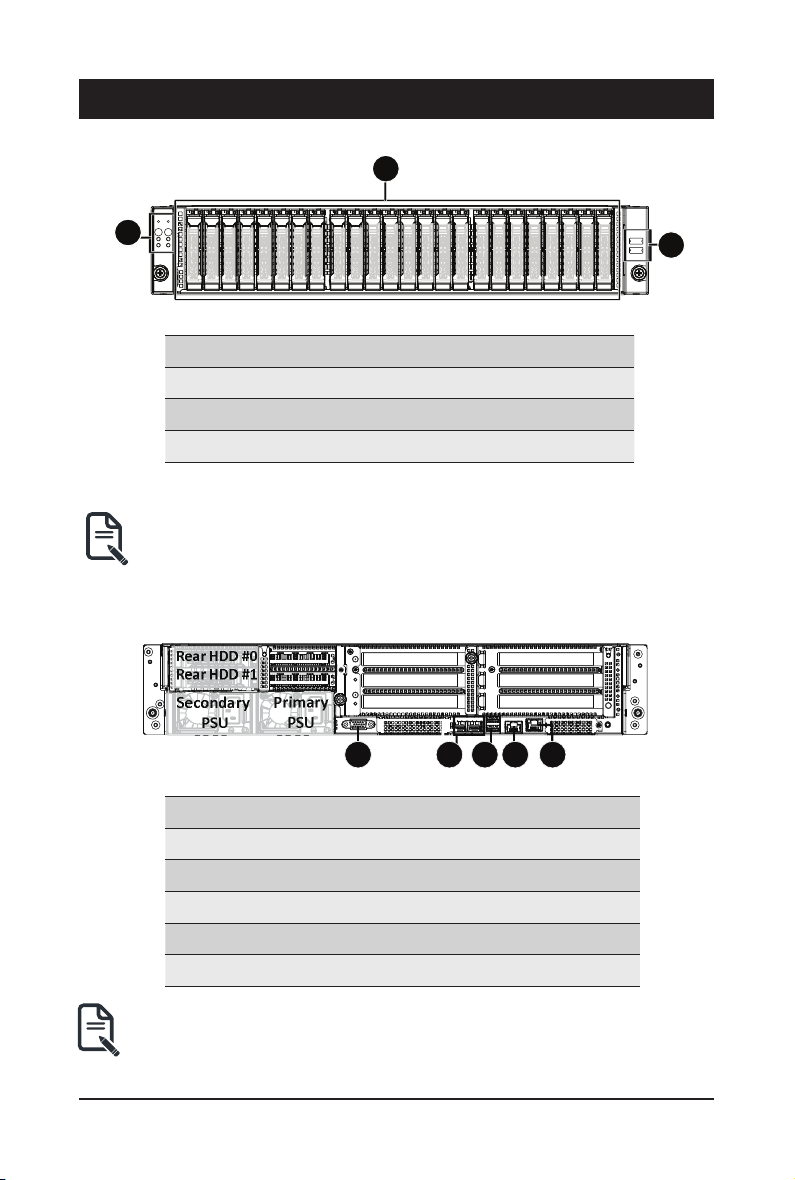
2-1 Front View
No. Description
1.
2. HDD Bays
3. Front USB 3.0 ports
• Refer to Chapter 2-3 Front Panel LED and Buttons for a detailed description of the function
of the LEDs.
2-2 Rear View
Rear HDD #0
Rear HDD #1
Secondary
PSU
Front Panel LEDs and buttons
Primary
PSU
1 2 4 53
No. Description
1. VGA port
2. 10 GbE SFP+ LAN Port x 2
3. USB 3.0 Port x 2
4. COM Port (RJ45 type)
5. 10/100/1000 Server management LAN port
• Refer to Chapter 2-4 Rear System LAN LEDs for a detailed description of the function of
the LEDs.
- 15 - System Appearance
Page 16
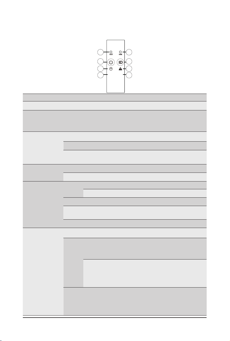
2-3 Front Panel LED and Buttons
1
3
5
L1
7
2
4
6
L2
8
No. Name Color Status Description
Reset Button -- -- Press this button to reset the system.
1.
Press this button for the server to generate a NMI to the
NMI button -- --
2.
Green On Indicates the system is powered on.
3.
4.
5.
6.
Power button
with LED
ID Button
with LED
HDD Status
LED
System
Status LED
Green Blink System is in ACPI S1 state (sleep mode).
N/A Off
Blue On Indicates the system identication is active.
N/A Off Indicates the system identication is disabled.
Green
Amber On
Green/
Amber
N/A Off
Green On
Amber
processor. If multiple-bit ECC errors occur, the server will
effectively be halted.
• System is not powered on or in ACPI S5 state (power off)
• System is in ACPI S4 state (hibernate mode)
On
Indicates locating the HDD.
Blink
Indicates accessing the HDD.
Indicates HDD error.
Blink
Indicates HDD rebuilding.
Indicates no HDD access or no HDD error.
Indicates system is operating normally.
Indicates a critical condition, may include:
On
-System fan failure
-System temperature
Indicates non-critical condition, may include:
Blink
-Redundant power module failure
-Temperature and voltage issue
Indicates system is not ready, may include:
N/A Off
System Appearance - 16 -
-POST error
-NMI error
-Processor or terminator is missing
Page 17

7.
8.
LAN1 Active/
Link LED
LAN2 Active/
Link LED
Green On
Green Blink
N/A Off
Green
Green Blink
N/A Off
On
Indicates a link between the system and the network or
no access.
Indicates data trasmission or receiving is occuring.
Indicates no data transmission or receiving is occuring.
Indicates a link between the system and the network or
no access.
Indicates data trasmission or receiving is occuring.
Indicates no data transmission or receiving is occuring.
- 17 - System Appearance
Page 18

2-4 Rear System LAN LEDs
3 4
1 2
No. Name Color Status Description
Yel low On 10 Gbps data rate
10GbE
1.
2.
3.
4.
Speed LED
10GbE
Link/
Activity
LED
1GbE
Speed LED
1GbE
Link/
Activity
LED
Green On 1 Gbps data rate
N/A Off 100 Mbps data rate
On Link between system and
Green
Blink Data transmission or receiving is occurring
N/A Off No data transmission or
Yel low On 1 Gbps data rate
Green On 100 Mbps data rate
N/A Off 10 Mbps data rate
On Link between system and
Green
Blink Data transmission or receiving is occurring
N/A Off No data transmission or
21
network or no access
receiving is occurring
network or no access
receiving is occurring
System Appearance - 18 -
Page 19
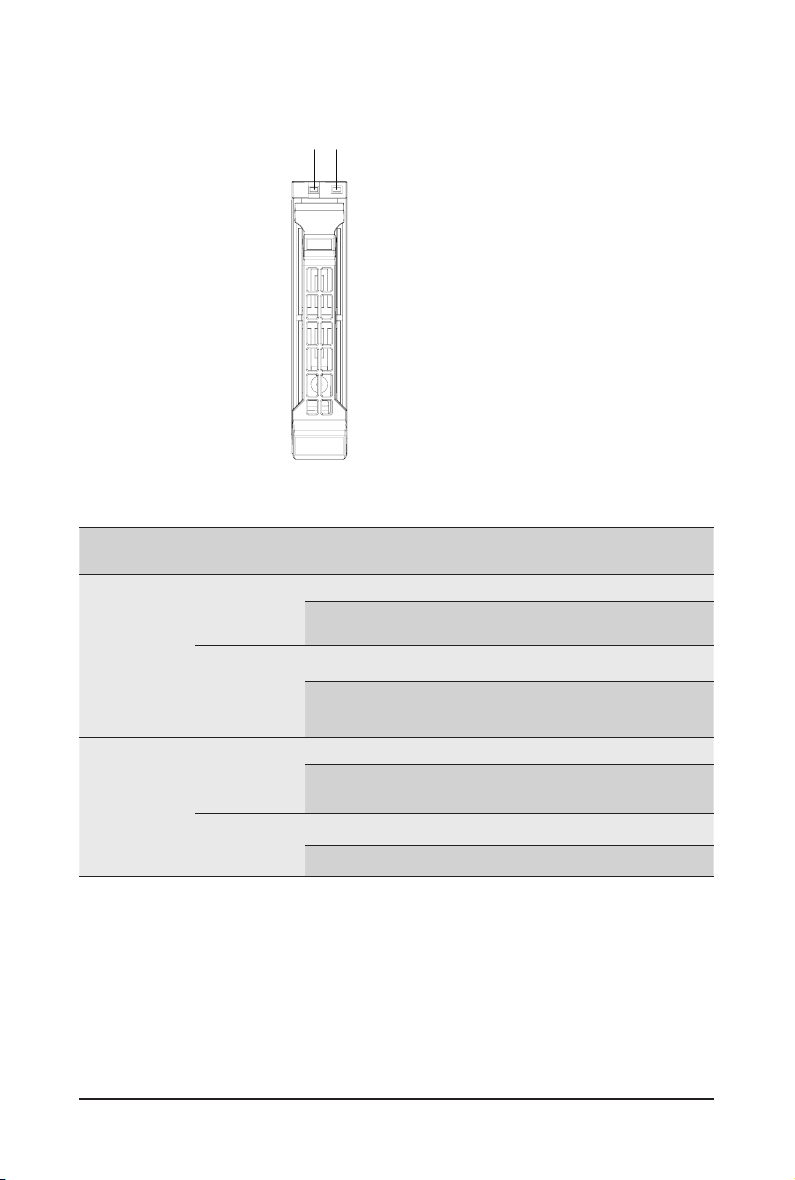
2-5 Hard Disk Drive LEDs
LED#1
LED#2 (Reserved/No Function)
RAID SKU LED #1 Locate HDD
No RAID
conguration
(via HBA, ICH)
conguration
(via HW RAID
Card, or SW
RAID Card)
NOTE:
*1: Depends on HBA/Utility Spec.
*2: Blink cycle depends on HDD's activity signal.
*3: If HDD is pulled out during rebuilding, the disk status of this HDD is regarded as faulty.
RAID
Disk LED
(LED on
Back Panel)
Removed
HDD Slot
(LED on
Back Panel)
Disk LED
Removed
HDD Slot
Rebuilding HDD
Fault
Access
HDD Present
(No Access)
Green O N(*1) OFF Green OFF
Amber OFF OFF Amber OFF
Green O N(*1) OFF Green --
Amber OFF OFF Amber --
Green ON OFF Alternately OFF
Amber OFF ON
(Low Speed:
2 Hz)
OFF
Green O N(*1) OFF (*3) --
Amber OFF ON (*3) --
- 19 - System Appearance
Page 20
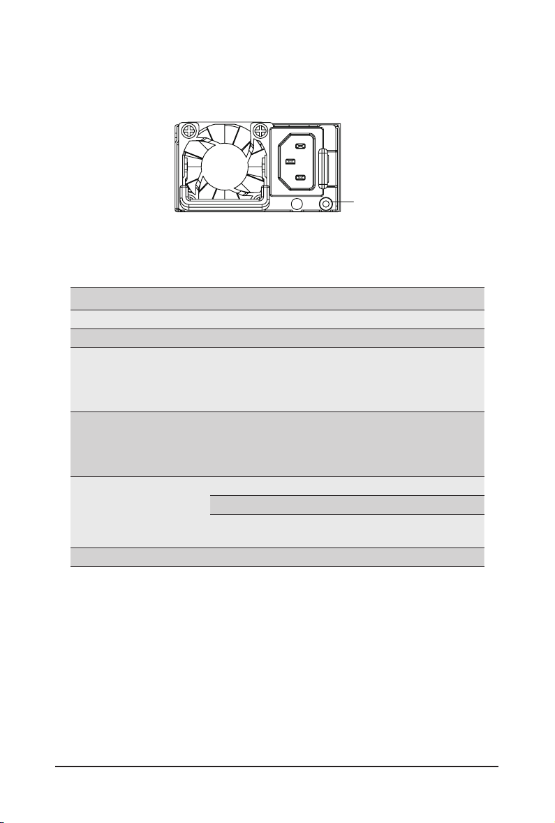
2-6 Power Supply Unit LED
State Description
Green ON Output ON and OK
Off No AC power to all power supplies
Green BLINKING
1 Sec./On
1 Sec./Off
0.5Hz
Green BLINKING
0.25 Sec./On
0.25 Sec./Off
2Hz
Amber
Amber (*3)
PSU Sleep Mode (cold Redundant/Ofine mode)
PSU LED
Standby Mode (normal)
Standby Mode (with OTP range)
12V Fault (OVP, UVP, OCP, SCP, and OTP)
Power Supply fan lock (15 seconds
including Standby mode)
System Appearance - 20 -
Page 21

Chapter 3 System Hardware Installation
Pre-installation Instructions
Computer components and electronic circuit boards can be damaged by discharges of static
electricity. Working on computers that are still connected to a power supply can be extremely
dangerous. Follow the simple guidelines below to avoid damage to your computer or injury to
yourself.
• Always disconnect the computer from the power outlet whenever you are working inside the
computer case.
• If possible, wear a grounded wrist strap when you are working inside the computer case.
Alternatively, discharge any static electricity by touching the bare metal system of the computer
case, or the bare metal body of any other grounded appliance.
• Hold electronic circuit boards by the edges only. Do not touch the components on the board
unless it is necessary to do so. Do not ex or stress the circuit board.
• Leave all components inside the static-proof packaging until you are ready to use the component
for the installation.
- 21 - System Hardware Installation
Page 22

3-1 Removing and Installing the Chassis Cover
Before you remove or install the system cover
• Make sure the system is not turned on or connected to AC power.
Follow these instructions to remove the chassis covers:
1. Loosen and remove the thumbscrew securing the chassis cover.
2. Push down on the indentations located on the side of the chassis cover.
3. Slide the chassis cover to the rear of the system and then remove the cover in the direction of the
arrow.
4. To reinstall the chassis cover follow steps 1-3 in reverse order.
2
3
2
2
1
System Hardware Installation - 22 -
Page 23

3-2 Removing and Installing the Fan Duct
Follow these instructions to remove the fan duct:
1. Lift up to remove the fan duct.
2. To reinstall the fan duct, align the fan duct with the guiding groove. Push down the fan duct until it is
rmly seated on the system.
1
2
- 23 - System Hardware Installation
Page 24

3-3 Removing and Installing Memory
Read the following guidelines before you begin to install the memory:
• Make sure that the motherboard supports the memory. It is recommended that memory of the
same capacity, brand, speed, and chips be used.
• Always turn off the computer and unplug the power cord from the power outlet before installing
the memory to prevent hardware damage.
• Memory modules have a foolproof design. A memory module can be installed in only one
direction. If you are unable to insert the memory, switch the direction.
3-3-1 Eight-Channel Memory Conguration
This motherboard provides 32 DDR4 memory sockets and supports Eight Channel Technology. After the
memory is installed, the BIOS will automatically detect the specications and capacity of the memory.
21
CPU0
(Primary)
DIMM_P0_A0
DIMM_P0_A1
DIMM_P0_C0
DIMM_P0_C1
DIMM_P0_E0
DIMM_P0_D1
DIMM_P0_D0
DIMM_P0_B1
DIMM_P0_B0
DIMM_P0_H0
DIMM_P0_F0
DIMM_P0_G0
System Hardware Installation - 24 -
DIMM_P1_L1
DIMM_P1_L0
DIMM_P1_J1
DIMM_P1_J0
DIMM_P1_P0
DIMM_P1_N0
CPU1
(Secondary)
DIMM_P1_K0
DIMM_P1_K1
DIMM_P1_M0
DIMM_P1_O0
DIMM_P1_I0
DIMM_P1_I1
Page 25

3-3-2 Removing and Installing a Memory Module
Before installing a memory module, make sure to turn off the computer and unplug the power
cord from the power outlet to prevent damage to the memory module.
Be sure to install DDR4 DIMMs on to this motherboard.
Follow these instructions to install a DIMM module:
1. Insert the DIMM memory module vertically into the DIMM slot and push it down.
2. Close the plastic clip at both edges of the DIMM slots to lock the DIMM module.
3. Reverse the installation steps when you want to remove the DIMM module.
2
1
2
3-3-3 DIMM Population Table
Speed (MT/s); Voltage (V)
Slot Per Channel (SPC)
Type
Ranks Per
DIMM and
Data Width
DIMM
Capacity
(GB)
DIMM Per Channel (DPC)
1 Slot per
Channel
2 Slots per
Channel
RDIMM
RDIMM
RDIMM
SRx4
DRx8
DRx4
DIMM Density
4Gb8Gb
NA 16GB
8GB 16GB
16GB 32GB
- 25 - System Hardware Installation
1DPC
1.2V
2666
1DPC
1.2V
2666
2DPC
1.2V
2400
Page 26

3-4 Removing and Installing the PCI Expansion Card
• Voltages can be present within the server whenever an AC power source is connected. This
voltage is present even when the main power switch is in the off position. Ensure that the system
is powered off and all power sources have been disconnected from the server prior to installing a
PCIe card.
• Failure to observe these warnings could result in personal injury or damage to equipment.
• The PCI riser assembly does not include a riser card or any cabling as standard. To install a
PCIe card, a riser card must be installed.
Follow these instructions to PCI Expansion card:
1. Loosen and remove the thumbscrew on the riser bracket.
2. Remove the screw securing the riser bracket.
3. Lift up the riser bracket out of system.
4. Loosen and remove the screw securing the slot cover from riser bracket.
5. Orient the PCIe card with the riser guide slot and push in the direction of the arrow until the PCIe
card sits in the PCIe card connector.
NOTE: Some riser brackets allow for single or multiple PCIe cards. Repeat steps 4-5 as necessary.
6. Secure the PCIe card with the screw.
7. Reverse steps 1-3 to install the riser bracket.
1
System Hardware Installation - 26 -
1
2
2
Page 27

7
5
6
3
3
3
4
4
5
7
6
6
5
7
- 27 - System Hardware Installation
Page 28

3-5 Removing and Installing the Hard Disk Drive
Read the following guidelines before you begin to install the hard disk drive:
• Take note of the drive tray orientation before sliding it out.
• The tray will not t back into the bay if it is inserted incorrectly.
• Make sure that the HDD is connected to the HDD connector on the backplane.
Follow these instructions to install a hard disk drive:
1. Press the release button.
2. Extend the locking lever.
3. Pull the locking lever in the direction of the arrow to remove the HDD tray.
4. Slide the hard disk into the HDD tray.
5. Install 4 screws to secure the hard drive to the HDD tray.
6. Reinsert the HDD tray into the slot and close the locking lever.
1
2
3
5
System Hardware Installation - 28 -
4
5
Page 29

3-6 Replacing the Fan Assembly
Follow these instructions to replace a fan assembly:
1. Flip the latches on the top of the fan outwards.
2. Using the latches, lift up the fan assembly from the chassis.
3. Reverse the previous steps to install the replacement fan assembly.
1
2
- 29 - System Hardware Installation
Page 30

3-7 Removing and Installing the Power Supply
Before you remove or install the power supply unit:
• Make sure the system is not turned on or connected to AC power.
Follow these instructions to replace the power supply:
1. Press the retaining clip on the left side of the power supply unit along the direction of the arrow.
2. Pull the power supply handle at the same time and pull out the power supply unit.
3. Insert the replacement power supply unit rmly into the chassis. Connect the AC power cord to the
replacement power supply.
4. Repeat steps 1-3 for replacement of the second power supply.
1
2
System Hardware Installation - 30 -
3
Page 31

3-8 Cable Routing
Front Panel Board Cable
Rear HDD Back Panel Board Power Cable
Front Panel USB 3.0 Cable
Rear HDD Back Panel Board Signal Cable
- 31 - System Hardware Installation
Page 32

SAS Expansion Card to Back Plane Board
Cable #0/#1/#2
SAS Expansion Card to Back Plane Board
Cable #3/#4/#5
0
1
2
SAS Expansion Card Power Cable
3
4
5
On-Board SATA to HDD Back Plane Board
Cable #0/#1
01
System Hardware Installation - 32 -
Page 33

HDD Back Panel Board Power Cable HDD Back Panel Board Signal Cable
System Fan Cable
- 33 - System Hardware Installation
Page 34

This page intentionally left blank
System Hardware Installation - 34 -
Page 35

Chapter 4 Motherboard Components
ON
4-1 Motherboard Components
OFF
10
8
21
7
6
8
9
5
4
2
DIMM_P0_D1
DIMM_P0_D0
DIMM_P0_B1
DIMM_P0_B0
1
DIMM_P0_H0
DIMM_P0_F0
CPU0
(Primary)
3
11
14
12
13
DIMM_P0_E0
DIMM_P0_G0
DIMM_P0_A1
DIMM_P0_C0
DIMM_P0_C1
2223
14
17
DIMM_P1_J1
DIMM_P1_J0
DIMM_P0_A0
15
16
DIMM_P1_P0
DIMM_P1_N0
DIMM_P1_L1
DIMM_P1_L0
18 19
CPU1
(Secondary)
DIMM_P1_K0
DIMM_P1_K1
DIMM_P1_M0
DIMM_P1_O0
2021
DIMM_P1_I0
DIMM_P1_I1
Item Description
1 2 x 4 Pin GPGPU Power Connector
2 2 x 4 Pin GPGPU Power Connector
3 Front Panel Header
4 Front Panel USB 3.0 Connector
5 BMC Firmware Readiness LED
6 HDD Back Plane Board Connector
7 IPMB Connector
8* OCP Mezzanine Connector #1 (Supports NCSI Function)
9 System Battery
- 35 - Motherboard Components
Page 36

10 Riser Connector #2
11 SlimLine SAS Connector (SATA3/SAS/#4~#7/From LSI)
12 SlimLine SAS Connector (SATA3/SAS/#0~#3/From LSI)
13 2 x 4 Pin GPGPU Power Connector
14 OCP Mezzanine Connector #2
15 Riser Connector #3
16 Riser Connector #4
17 TPM Module Connector
18 Power Supply Connector #1 (Primary)
19 Power Supply Connector #2 (Secondary)
20 HDD Back Plane Board Power Connector (Rear HDD)
21* HDD Back Plane Board Power Connector (Front HDD)
22 SATA3 6Gb/s Connector #0
23 SATA3 6Gb/s Connector #1 (From CPU0)
24 Power supply connector#2 (secondary)
25 2 x 2 Pin extention card power connectors
26 2 x 7 Pin system main power connector
NOTE! Set the NCSI switch to On to enable NCSI fucnction.
Motherboard Components - 36 -
Page 37

4-2 Jumper Settings
NCSI Switch
Onboard LAN
21
OCP Connector #1
21
2&3B6(7
21',3
SLOT
PCIe Bandwidth
PCIe x16
PCIe x8/x8
PCIe x4/x4/x4/x4
OCP #1
Switch 4 and 3
ON and ON
ON and OFF ON and OFF
OFF and OFF
OCP #2
Switch 2 and 1
ON and ON
OFF and OFF
DIMM_P0_D0
DIMM_P0_D1
DIMM_P0_F0
DIMM_P0_H0
6<6B-3
DIMM_P0_B0
DIMM_P0_B1
21',3
1
2
3
4
CPU0
(Primary)
RVSD
CLR_PASSWD
RVSD
RVSD
DIMM_P1_J0
DIMM_P1_J1
DIMM_P1_L0
DIMM_P1_L1
DIMM_P1_N0
DIMM_P1_P0
DIMM_P0_G0
DIMM_P0_E0
DIMM_P0_C1
DIMM_P0_C0
DIMM_P0_A1
DIMM_P0_A0
ON
Reserved/No Function
Clear supervisor password
Reserved/No Function
Reserved/No Function Reserved/No Function
OFF
Reserved/No Function
Normal [Default]
Reserved/No Function
- 37 - Motherboard Components
CPU1
(Secondary)
DIMM_P1_K1
DIMM_P1_K0
DIMM_P1_I1
DIMM_P1_I0
DIMM_P1_O0
DIMM_P1_M0
Page 38

This page intentionally left blank
Motherboard Components - 38 -
Page 39

Chapter 5 BIOS Setup
BIOS (Basic Input and Output System) records hardware parameters of the system in the EFI on the
motherboard. Its major functions include conducting the Power-On Self-Test (POST) during system startup,
saving system parameters and loading operating system, etc. BIOS includes a BIOS Setup program that
allows the user to modify basic system conguration settings or to activate certain system features. When the
power is turned off, the battery on the motherboard supplies the necessary power to the CMOS to keep the
conguration values in the CMOS.
To access the BIOS Setup program, press the <F2> or <ESC> key during the POST when the power is
turned on.
• BIOS ashing is potentially risky, if you do not encounter problems of using the current BIOS
version, it is recommended that you don't ash the BIOS. To ash the BIOS, do it with caution.
Inadequate BIOS ashing may result in system malfunction.
• It is recommended that you not alter the default settings (unless you need to) to prevent system
instability or other unexpected results. Inadequately altering the settings may result in system's
failure to boot. If this occurs, try to clear the CMOS values and reset the board to default values.
(Refer to the Exit section in this chapter or introductions of the battery/clearing CMOS jumper in
Chapter 1 for how to clear the CMOS values.)
BIOS Setup Program Function Keys
<f><g> Move the selection bar to select the screen
<h><i> Move the selection bar to select an item
<+> Increase the numeric value or make changes
<-> Decrease the numeric value or make changes
<Enter> Execute command or enter the submenu
<Esc> Main Menu: Exit the BIOS Setup program
Submenus: Exit current submenu
<F1> Show descriptions of general help
<F3> Restore the previous BIOS settings for the current submenus
<F9> Load the Optimized BIOS default settings for the current submenus
<F10> Save all the changes and exit the BIOS Setup program
- 39 - BIOS Setup
Page 40

Main
This setup page includes all the items in standard compatible BIOS.
Advanced
This setup page includes all the items of AMI BIOS special enhanced features.
(ex: Auto detect fan and temperature status, automatically congure hard disk parameters.)
Chipset
This setup page includes all the submenu options for conguring the function of processor, network,
North Bridge, South Bridge, and System event logs.
Security
Change, set, or disable supervisor and user password. Conguration supervisor password allows you to
restrict access to the system and BIOS Setup.
A supervisor password allows you to make changes in BIOS Setup.
A user password only allows you to view the BIOS settings but not to make changes.
Boot
This setup page provides items for conguration of boot sequence.
Save & Exit
Save all the changes made in the BIOS Setup program to the CMOS and exit BIOS Setup. (Pressing
<F10> can also carry out this task.)
Abandon all changes and the previous settings remain in effect. Pressing <Y> to the confirmation
message will exit BIOS Setup. (Pressing <Esc> can also carry out this task.)
Server Management
Server additional features enabled/disabled setup menus.
BIOS Setup - 40 -
Page 41

5-1 The Main Menu
Once you enter the BIOS Setup program, the Main Menu (as shown below) appears on the screen. Use
arrow keys to move among the items and press <Enter> to accept or enter other sub-menu.
Main Menu Help
The on-screen description of a highlighted setup option is displayed on the bottom line of the Main Menu.
Submenu Help
While in a submenu, press <F1> to display a help screen (General Help) of function keys available for the
menu. Press <Esc> to exit the help screen. Help for each item is in the Item Help block on the right side of
the submenu.
• When the system is not stable as usual, select the Restore Defaults item to set your system
to its defaults.
• The BIOS Setup menus described in this chapter are for reference only and may differ by
BIOS version.
- 41 - BIOS Setup
Page 42

Parameter Description
BIOS Information
Access Level Displays the access privilege level information.
Project Name
(Note)
Displays the project name information.
Project Version Displays version number of the BIOS setup utility.
Build Date and Time Displays the date and time when the BIOS setup utility was created.
BMC Information
BMC Firmware Version
(Note)
(Note)
Displays BMC rmware version information.
Processor Information
Displays the technical specications for the installed processor(s).
Memory Information
Total Memory
Memory Frequency
(Note)
(Note)
Displays the total memory size of the installed memory.
Displays the frequency information of the installed memory.
Memory Slot Information Press [Enter] to view the installed memory information.
Onboard LAN MAC Address
Information
LAN1 MAC Address
LAN2 MAC Address
(Note)
(Note)
(Note)
Displays LAN MAC address information.
Displays LAN MAC address information.
(Note) Corresponds to the model name of GIGABYTE server you are using.
BIOS Setup - 42 -
Page 43

Parameter Description
System Date Sets the date following the weekday-month-day-year format.
System Time Sets the system time following the hour-minute-second format.
- 43 - BIOS Setup
Page 44

5-2 Advanced Menu
The Advanced menu display submenu options for conguring the function of various hardware components.
Select a submenu item, then press [Enter] to access the related submenu screen.
BIOS Setup - 44 -
Page 45

5-2-1 Trusted Computing
Parameter Description
Conguration
Security Device Support
Current Status Information Displays current TPM status information.
Enable/Disable the TPM support feature.
Options available: Enable/Disable. Default setting is Enable.
- 45 - BIOS Setup
Page 46

5-2-2 S5 RTC Wake Setting
Parameter Description
Enable or disable System wake on alarm event. When enabled, System
(Note)
Wake system from S5
Wake up year Press <+> and <-> to dene the wake up year.
Wake up month Press <+> and <-> to dene the wake up month.
Wake up Date Press <+> and <-> to dene the wake up date.
Wake up hour Press <+> and <-> to dene the wake up hour.
Wake up minute Press <+> and <-> to dene the wake up minute.
Wake up second Press <+> and <-> to dene the wake up second.
will wake on the hr:min:sec specied.
Default setting is Disabled.
(Note) This item appears when Wake system from S5 is set to Enabled.
BIOS Setup - 46 -
Page 47

5-2-3 Network Stack Conguration
Parameter Description
Network Stack
Ipv4 PXE Support
Ipv4 HTTP Support
Ipv6 PXE Support
Ipv6 HTTP Support
PXE boot wait time
Media detect count
(Note)
(Note)
(Note)
(Note)
(Note)
(Note)
Enable/Disable the UEFI network stack.
Options available: Enabled/Disabled. Default setting is Enabled.
Enable/Disable the Ipv4 PXE feature.
Options available: Enabled/Disabled. Default setting is Enabled.
Enable/Disable the Ipv4 HTTP feature.
Options available: Enabled/Disabled. Default setting is Disabled.
Enable/Disable the Ipv6 PXE feature.
Options available: Enabled/Disabled. Default setting is Disabled.
Enable/Disable the Ipv6 HTTP feature.
Options available: Enabled/Disabled. Default setting is Disabled.
Press the <+> / <-> keys to increase or decrease the desired values.
Press the <+> / <-> keys to increase or decrease the desired values.
(Note) This item appears when Network Stack is set to Enabled.
- 47 - BIOS Setup
Page 48

5-2-4 Info Report Conguration
Parameter Description
Info Report Conguration
Post Report
Post Report
Delay Time
Error Message Report
Post Error Message
Enable/Disable the POST Report support.
Options available: Enabled/Disabled. Default setting is Enabled.
Post Report wait time 0~10 seconds.
Options available: 0/1/2/3/4/5/6/7/8/9/Until Press ESC.
Enable/Disable the POST Error Message support.
Options available: Enabled/Disabled. Default setting is Enabled.
BIOS Setup - 48 -
Page 49

5-2-5 NMVe Conguration
Parameter Description
NVMe Conguration Displays the NVMe devices connected to the system.
- 49 - BIOS Setup
Page 50

5-2-6 SATA Conguration
Parameter Description
SATA Conguration
SATA Controller # Displays the SATA device connected to the system.
BIOS Setup - 50 -
Page 51

5-2-7 USB Conguration
Parameter Description
USB Conguration
USB Module Version Displays the USB module version information.
USB Controller Displays the USB controller information.
USB Devices: Displays the USB devices connected to the system.
XHCI Hand-off
USB Mass Storage Driver
(Note)
Support
Enable/Disable the XHCI (USB 3.0) Hand-off support.
Options available: Enabled/Disabled. Default setting is Enabled.
Enable/Disable the USB Mass Storage Driver Support.
Options available: Enabled/Disabled. Default setting is Enabled.
(Note) This item is present only if you attach USB devices.
- 51 - BIOS Setup
Page 52

5-2-8 Chipset Conguration
Parameter Description
Denes the power state to resume to after a system shutdown that is
due to an interruption in AC power. When set to Last State, the system
will return to the active power state prior to shutdown. When set to
Restore on AC Power Loss
Skip Above 4G Decoding for VGA
P2P Bridge IO Size
Chassis Opened Warning
(Note)
Power Off, the system remains off after power shutdown.
Options available: Last State/Power Off/Power On. The default setting
depends on the BMC setting.
Enable/Disable 64bit capable devices to be decoded in Skip Above 4G
Address VGA Space.
Options available: Enabled/Disabled. Default setting is Disabled.
Sets P2P Bridge IO aligned to the size.
Options available: 0x100/0x150/0x1000. Default setting is 0x1000.
Enable/Disable the chassis intrusion alter function.
Options available: Enabled/Disabled/Clear. Default setting is
Disabled.
(Note) When the power policy is controlled by BMC, please wait for 15-20 seconds for BMC to save the
last power state.
BIOS Setup - 52 -
Page 53

5-2-9 Ethernet Adapter Conguration
Parameter Description
Firmware Image Properties Press [Enter] to access the related submenu screen.
Device Level Conguration Press [Enter] to access the related submenu screen.
Port Level Conguration Press [Enter] to access the related submenu screen.
Partitioning Mode
Device Name
Chipset Type
PCI Device ID
PCI Address
Link Status
Link Speed
Permanent MAC Address
Virtual MAC Address
Options available: Default/NPAR.
Default setting is Default.
Displays the technical specications for the Network Interface
Controller.
Displays the technical specications for the Network Interface
Controller.
Displays the technical specications for the Network Interface
Controller.
Displays the technical specications for the Network Interface
Controller.
Displays the technical specications for the Network Interface
Controller.
Displays the technical specications for the Network Interface
Controller.
Displays the technical specications for the Network Interface
Controller.
Displays the technical specications for the Network Interface
Controller.
- 53 - BIOS Setup
Page 54

5-2-10 MAC IPv4 Network Conguration
Parameter Description
Conguraed
Enable DHCP
Local IP Address Press [Enter] to congigure Local IP address.
Local NetMask Press [Enter] to congigure Local NetMask.
Local Gateway Press [Enter] to congigure Local Gateway.
Local DNS Servers Press [Enter] to congigure Local DNS Server.
Save Changes and Exit
Option available: Enabled/Disabled.
Default setting is Enabled.
Option available: Enabled/Disabled.
Default setting is Enabled.
When you nish the conguration in this page, press enter to save and
to exit the conguration.
BIOS Setup - 54 -
Page 55

5-2-11 MAC IPv6 Network Conguration
Parameter Description
Enter Conguration Menu Press [Enter] to access the related submenu screen.
- 55 - BIOS Setup
Page 56

5-3 Chipset Setup Menu
Parameter Description
SOC Conguration
Selects CPPC OS Scaling for Turbo and Non-Turbo options.
Default will run cores ar a nomimal supported frequency.
Turbo/CCPC Mode
Symmertic Multi-Treading
DDR Speed
Option avaiable: Default/Autonomous - CPPC off/Autonomous - CPPC
On/ OSPM Turbo/ OSPM Non-Turbo.
Default setting is Default.
Option avaiable: 4/2/1.
Default setting is 4.
Option avaiable: Auto/1600/1866/2133/2400/2666
Default setting is Auto.
BIOS Setup - 56 -
Page 57

5-4 Security Menu
The Security menu allows you to safeguard and protect the system from unauthorized use by setting up
access passwords.
There are two types of passwords that you can set:
• Administrator Password
Entering this password will allow the user to access and change all settings in the Setup Utility.
• User Password
Entering this password will restrict a user’s access to the Setup menus. To enable or disable
this eld, a Administrator Password must rst be set. A user can only access and modify the
System Time, System Date, and Set User Password elds.
Parameter Description
Administrator Password Press [Enter] to congure the administrator password.
User Password Press [Enter] to congure the user password.
- 57 - BIOS Setup
Page 58

5-5 Boot Menu
The Boot menu allows you to set the drive priority during system boot-up. BIOS setup will display an error
message if the legacy drive(s) specied is not bootable.
BIOS Setup - 58 -
Page 59

Parameter Description
Boot Conguration
Number of seconds to wait for setup activation key. 65535 (0xFFFF)
Setup Prompt Timeout
Bootup NumLock State
Quiet Boot
FIXED BOOT ORDER
Priorities
Boot Option #1 / #2 / #3 / #4 /
#5
UEFI sUEFI Application Boot
Priorities
UEFI Network Drive BBS
Prioritie
means indenite waiting.
Press the numeric keys to input the desired values.
Enable/Disable the Bootup NumLock function.
Options available: On/Off. Default setting is On.
Enable/Disable showing the logo during POST.
Options available: Enabled/Disabled. Default setting is Enabled.
Press [Enter] to congure the boot priority.
By default, the server searches for boot devices in the following
sequence:
1. Hard drive.
2. CD-COM/DVD drive.
3. USB device.
4. Network.
5. UEFI.
Press [Enter] to congure the boot priority.
Press [Enter] to congure the boot priority.
- 59 - BIOS Setup
Page 60

5-5-1 UEFI Application Boot Priorities
The UEFI application boot priorities submenu allows you to specify the boot device priority from the available
UEFI applications during system boot-up. BIOS setup will display an error message if the legacy drive(s)
specied is not bootable.
BIOS Setup - 60 -
Page 61

5-5-2 UEFI NETWORK Drive BBS Priorities
The UEFI network drive BBS priorities submenu allows you to specify the boot device priority from the
available UEFI network drives during system boot-up. BIOS setup will display an error message if the legacy
drive(s) specied is not bootable.
- 61 - BIOS Setup
Page 62

5-6 Save & Exit Menu
The Exit menu displays the various options to quit from the BIOS setup. Highlight any of the exit options then
press Enter.
BIOS Setup - 62 -
Page 63

Parameter Description
Save Options
Save Changes and Exit
Discard Changes and Exit
Save Changes and Reset
Discard Changes and Reset
Save Changes
Discard Changes
Default Options
Restore Defaults
Save as User Defaults
Restore User Defaults
Boot Override Press [Enter] to congure the device as the boot-up drive.
Saves changes made and closes the BIOS setup.
Options available: Yes/No.
Discards changes made and exits the BIOS setup.
Options available: Yes/No.
Restarts the system after saving the changes made.
Options available: Yes/No.
Restarts the system without saving any changes.
Options available: Yes/No.
Saves changes made in the BIOS setup.
Options available: Yes/No.
Discards changes made and closes the BIOS setup.
Options available: Yes/No.
Loads the default settings for all BIOS setup parameters. Setup Defaults
are quite demanding in terms of resources consumption. If you are using
low-speed memory chips or other kinds of low-performance components
and you choose to load these settings, the system might not function
properly.
Options available: Yes/No.
Saves the changes made as the user default settings.
Options available: Yes/No.
Loads the user default settings for all BIOS setup parameters.
Options available: Yes/No.
- 63 - BIOS Setup
Page 64

5-7 Server Management Menu
Parameter Description
BMC Self Test
Status
BMC Device ID Displays BMC device ID information.
BMC Device
Revision
BMC Firmware
Revision
IPMI Version Displays IPMI version information.
BMC Interface (s) Displays BMC interface information.
System Event Log Press [Enter] to congure advanced items.
BMC Self Test Log Press [Enter] to congure advanced items.
View FRU
Information
BMC network
conguration
Displays BMC Self Test status information.
Displays BMC device revision information.
Displays BMC rmware revision information.
Press [Enter] to view the advanced items.
Press [Enter] to congure advanced items.
(Note) Advanced items prompt when this item is set to Enabled.
BIOS Setup - 64 -
Page 65

5-7-1 System Event Log
Parameter Description
Enabling / Disabling Options
Change this item to enable or disable all features of System Event
SEL Components
Erasing Settings
Erasing SEL
When SEL is Full
Custom EFI Logging Options
Log EFI Status Codes
Logging during boot.
Options available: Enabled/Disabled. Default setting is Enabled.
Choose options for erasing SEL.
Options available: No/Yes, On next reset/Yes, On every reset. Default
setting is No.
Choose options for reactions to a full SEL.
Options available: Do Nothing/Erase Immediately. Default setting is Do
Nothing.
Enable/Disable the logging of EFI Status Codes (if not already converted
to legacy).
Options available: Disabled/Both/Error code/Progress code. Default
setting is Error code.
- 65 - BIOS Setup
Page 66

5-7-2 View Self Test Log
Parameter Description
Log area usage = 00 out of 20
logs
Choose options for erasing log.
Erase Log
When log is full
Options available: No/Yes, On next reset/Yes, On every reset. Default
setting is No..
Choose options for reactions to a full log.
Options available: Do Nothing/Clear Log. Default setting is Clear Log.
BIOS Setup - 66 -
Page 67

5-7-3 View FRU Information
The FRU page is a simple display page for basic system ID information, as well as System product
information. Items on this window are non-congurable.
(Note) Corresponds to the model name of GIGABYTE server you are using.
- 67 - BIOS Setup
Page 68

5-7-4 BMC Network Conguration
Parameter Description
BMC network conguration
Switch NCSI and dedicated LAN and send KCS command.
Select NCSI and Dedicated
LAN
Lan Channel 1
Conguration Address source
Station IP address Displays IP Address information.
Subnet mask
Router IP address Displays the Router IP Address information.
Station MAC address Displays the MAC Address information.
Real-time synchronize BMC
network parameter values
Options available: Do Nothing/Mode1 (Dedicated)/Mode2(NSCI)/Mode3
(Failover).
Default setting is Mode1 (Dedicated).
Select to congure LAN channel parameters statically or dynamically
(DHCP). Do nothing option will not modify any BMC network parameters
during BIOS phase.
Options available: Unspecied/Static/DynamicBmcDhcp. Default setting
is DynamicBmcDhcp.
Displays Subnet Mask information.
Please note that the IP address must be in three digitals, for example,
192.168.000.001.
Press [Enter] to synchronize the BMC network parameter values.
BIOS Setup - 68 -
 Loading...