


MBBZ1AI
AMD® Fusion APU E-450 processor motherboard
User's Manual
Rev. 1201

Copyright
© 2012 GIGA-BYTE TECHNOLOGY CO., LTD. All rights reserved.
The trademarks mentioned in this manual are legally registered to their respective owners.
Disclaimer
Information in this manual is protected by copyright laws and is the property of GIGABYTE.
Changes to the specifications and features in this manual may be made by GIGABYTE
without prior notice. No part of this manual may be reproduced, copied, translated, transmitted, or
published in any form or by any means without GIGABYTE's prior written permission.
Documentation Classications
In order to assist in the use of this product, GIGABYTE provides the following types of documentation:
For detailed product information, carefully read the User's Manual.
For product-related information, check on our website at:
http://www.gigabyte.com

Table of Contents
Box Contents ...................................................................................................................4
MBBZ1AI Motherboard Layout ........................................................................................5
Chapter 1 Hardware Installation .....................................................................................7
1-1 Installation Precautions .................................................................................... 7
1-2 ProductSpecications ...................................................................................... 8
1-3 Installing the Memory ..................................................................................... 10
1-3-1 SingleChannelMemoryConguration ...................................................................10
1-3-2 Installing a Memory ...............................................................................................11
1-4 Back Panel Connectors .................................................................................. 12
1-5 Internal Connectors ........................................................................................ 14
Chapter 2 BIOS Setup ..................................................................................................24
2-1 The Main Menu .............................................................................................. 26
2-2 Advanced Menu ............................................................................................. 28
2-2-1 ACPI Settings .........................................................................................................29
2-2-2 CPUConguration ..................................................................................................30
2-2-3 SATAConguration.................................................................................................32
2-2-4 USBConguration ..................................................................................................33
2-2-5 F81214FirstSuperIOConguration ......................................................................34
2-2-6 F81214SecondSuperIOConguration ................................................................36
2-2-7 Network Stack ........................................................................................................38
2-3 Chipset Menu ................................................................................................. 39
2-3-1 SB Hardware Monitor .............................................................................................41
2-4 Boot Menu ...................................................................................................... 42
2-4-1 CSM parameters ...................................................................................................44
2-5 Security Menu ................................................................................................ 46
2-5-1 Secure Boot menu (Optional) .................................................................................47
2-5-1-1 Image Execution policy ..........................................................................................48
2-5-1-2 Key Management ..................................................................................................49
2-6 Save & Exit Menu ........................................................................................... 51
- 3 -

Box Contents
MBBZ1AI motherboard
Driver CD
Two SATA cables
I/O Shield
• The box contents above are for reference only and the actual items shall depend on the product package you obtain.
The box contents are subject to change without notice.
• The motherboard image is for reference only.
- 4 -
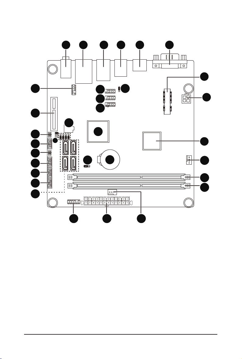
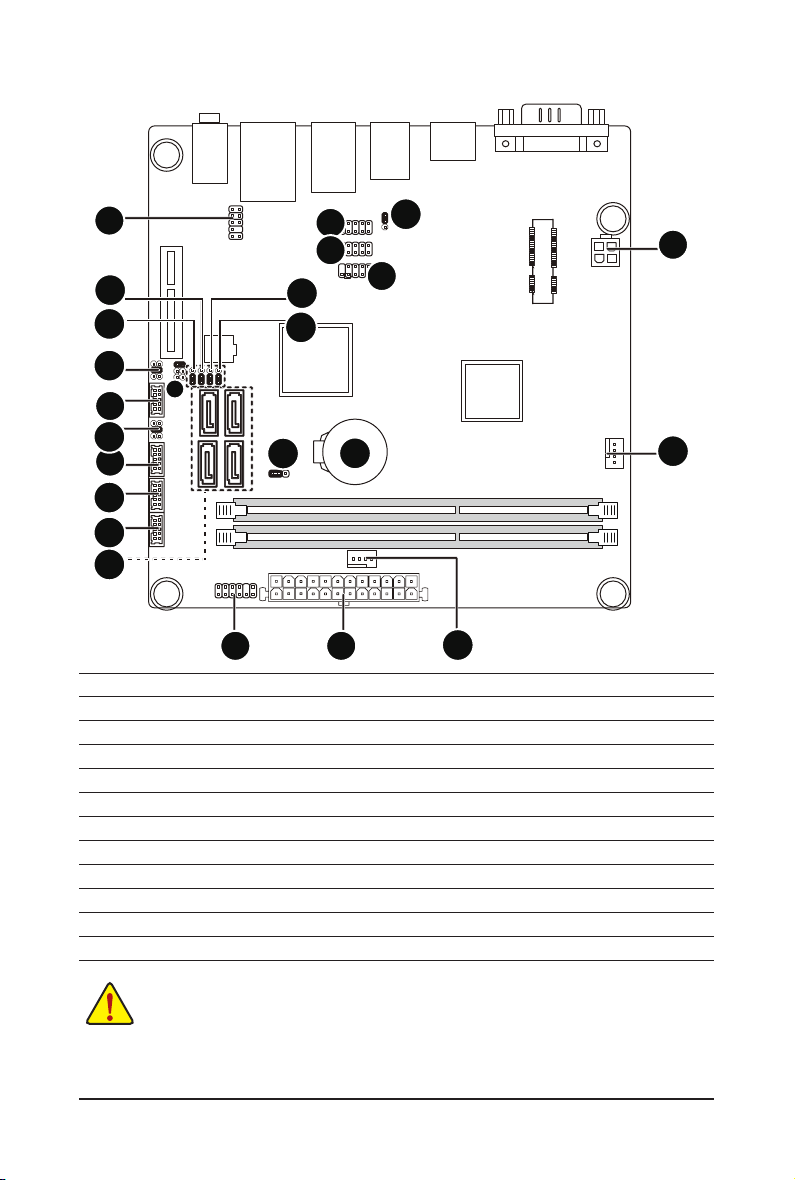
MBBZ1AI Motherboard Layout
29
28
26
24
23
22
21
20
19
1 2 3 4 6
30
31
32
27
18
25
17
16
5
33
131415
7
8
9
10
11
12
- 5 -

Item Code Description
1 AUDIO Audio connectors
2 USB_LAN
3 USB2 USB 2.0 ports
4 USB3 USB 3.0 ports
5 HDMI HDMI port
6 VGAVGA_DVI VGA port (top) / DVI-D port (buttom)
7 MPCIE1X Mini PCI Express connector
8 ATX_12V 4 pin power connector
9 U1 Embedded porcessor
10 CPU_FAN CPU fan connector
11 DDRIII_1 DDR3 SO-DIMM slot
12 DDRIII_2 DDR3 SO-DIMM slot
13 SYS_FAN System fan connector
14 ATX 24 pin power connector
15 F_PANEL Front panel header
16 BATTERY Battery socket
17 CLR_CMOS Clear CMOS jumper
18
U3
19 SATAIII_0/12/3 SATA 6Gb/s connectors
20 COM1 Serial port cable header
21 COM2 Serial port cable header
22 COM4 Serial port cable header
23
JCOM4
24 COM3 Serial port cable header
25 JRS4 RS232,RS422,RS485 Select jumper
26
JCOM3
27 BIOS BIOS Upgrade ROM
28 PCIE4X PCI Express x1 slot
29 F_AUDIO Audio cable connector
30 F_USB_1 Front USB header
31 F_USB_2 Front USB header
32 F_USB_3 Front USB header
33 USB_PWR USB header #1 power select jumper
RJ45 LAN port (top) / USB 2.0 ports
(buttom)
AMD Hudsion-M1 Fusion Controller
Hub (A50M)
Serial port #4 5V,12V, RI select
jumper
Serial port #3 5V,12V, RI select
jumper
- 6 -

Chapter 1 Hardware Installation
1-1 Installation Precautions
The motherboard contains numerous delicate electronic circuits and components which can
become damaged as a result of electrostatic discharge (ESD). Prior to installation, carefully read
the user's manual and follow these procedures:
• Prior to installation, do not remove or break motherboard S/N (Serial Number) sticker or
warranty sticker provided by your dealer. These stickers are required for warranty validation.
• Always remove the AC power by unplugging the power cord from the power outlet before
installing or removing the motherboard or other hardware components.
• When connecting hardware components to the internal connectors on the motherboard,
make sure they are connected tightly and securely.
• When handling the motherboard, avoid touching any metal leads or connectors.
• It is best to wear an electrostatic discharge (ESD) wrist strap when handling electronic com-
ponents such as a motherboard, CPU or memory. If you do not have an ESD wrist strap,
keep your hands dry and rst touch a metal object to eliminate static electricity.
• Prior to installing the motherboard, please have it on top of an antistatic pad or within an
electrostatic shielding container.
• Before unplugging the power supply cable from the motherboard, make sure the power sup-
ply has been turned off.
• Before turning on the power, make sure the power supply voltage has been set according to
the local voltage standard.
• Before using the product, please verify that all cables and power connectors of your hard-
ware components are connected.
• To prevent damage to the motherboard, do not allow screws to come in contact with the
motherboard circuit or its components.
• Make sure there are no leftover screws or metal components placed on the motherboard or
within the computer casing.
• Do not place the computer system on an uneven surface
• Do not place the computer system in a high-temperature environment.
• Turning on the computer power during the installation process can lead to damage to sys-
tem components as well as physical harm to the user.
• If you are uncertain about any installation steps or have a problem related to the use of the
product, please consult a certied computer technician.
.
- 7 - Hardware Installation
1-2 ProductSpecications
CPU Supports single AMD® Fusion APU E-450 processor
Supports Dual Core up to 1.65GHz
TDP 18W
Supports 1M Cache
Chipset AMD® FCH Hudson-D3 chipset
Memory 2 x 1.5V DDR3 slots
Max. to 8GB (4GB x 2)
Support for DDR3 800/1066 MHz
Display 1 x HDMI 1.3a
1 x DVI-D port
1 x VGA port
Audio Realtek ALC887 codec
High Denition Audio
5.1 Channel/Line in/Line out/MIC
LAN 1 x Realtek RTL8111E supports 10/100/1000 Mbps
Expansion Slots 1 x Mini PCI Express slot (Fullsize)
Onboard
Graphics
Storage Interface 4 x SATA 6Gb/s connectors
USB 2 x USB 3.0 ports (Rear I/O)
Internal
Connectors
Back Panel
Connectors
1 x PCI Express x4 solt
Build in Intel® processor
4 x USB 2.0 ports (Rear I/O)
3 x USB 2.0 headers
1 x 4 pin 12V power connector
1 x 10 pin power connector
4 x SATA 6Gb/s connectors
1 x CPU fan header
1 x System fan header
1 x Front panel header
1 x Front Audio header
3 x USB 2.0 header
4 x Serial port headers
3 x Serial port headers
1 x VGA Port
1 x DVI-D port
1 x HDMI port
2 x USB 3.0 ports
4 x USB 2.0 ports
3 x Audio connectors (1 x Line-out/ 1 x Line-in/ 1 x MIC)
- 8 - Hardware Installation

I/O Controller iTE IT81214 chip
Hardware
Monitor
CPU/System temperature detection
CPU fan speed detection
BIOS 1 x 16 Mbit ash
AMI BIOS
Form Factor Mini ITX Form Factor; 170cm x 170cm
* GIGA BYTE reserves the right to make any changes to the product specications and produc t-related infor mation
without prior notice.
Hardware Installation - 9 -
1-3 Installing the Memory
Read the following guidelines before you begin to install the memory:
• Make sure that the motherboard supports the memory. It is recommended that memory of the
same capacity, brand, speed, and chips be used.
• Always turn off the computer and unplug the power cord from the power outlet before installing
the memory to prevent hardware damage.
• Memory modules have a foolproof design. A memory module can be installed in only one
direction. If you are unable to insert the memory, switch the direction.
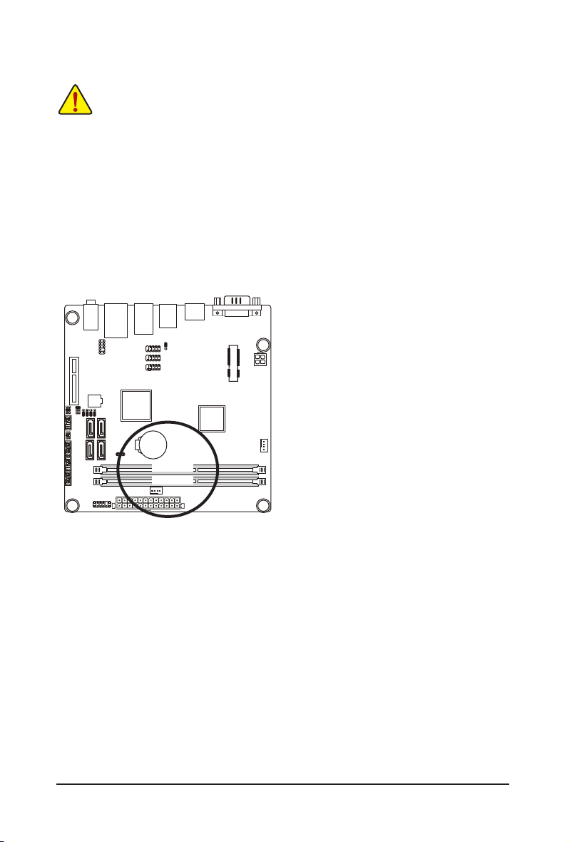
1-3-1 SingleChannelMemoryConguration
This motherboard provides two DDR3 memory sockets and supports Single Channel Technology. After the
memory is installed, the BIOS will automatically detect the specications and capacity of the memory. Enabling Dual Channel memory mode will double the original memory bandwidth.
DDRIII1
DDRIII2
Hardware Installation - 10 -
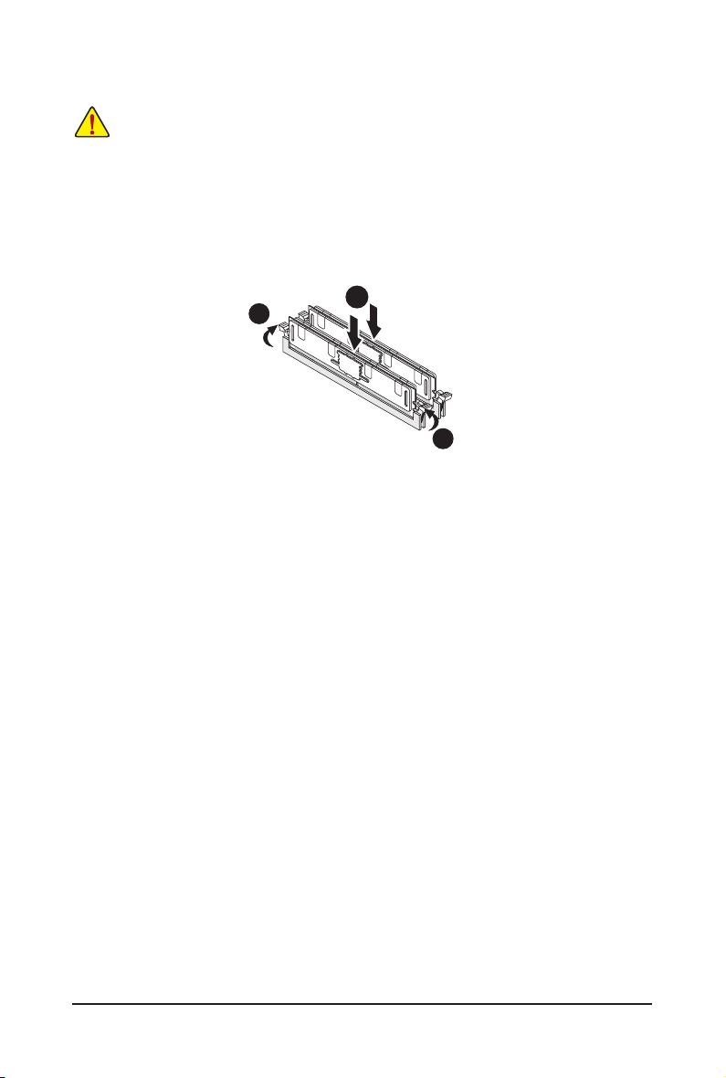
1-3-2 Installing a Memory
Before installing a memory module, make sure to turn off the computer and unplug the power
cord from the power outlet to prevent damage to the memory module.
Be sure to install DDR3 DIMMs on this motherboard.
Installation Step:
Step 1. Insert the DIMM memory module vertically into the DIMM slot, and push it down.
Step 2. Close the plastic clip at both edges of the DIMM slots to lock the DIMM module.
Note: For dual-channel operation, DIMMs must be installed in matched pairs.
Step 3. Reverse the installation steps when you wish to remove the DIMM module.
2
1
2
- 11 - Hardware Installation
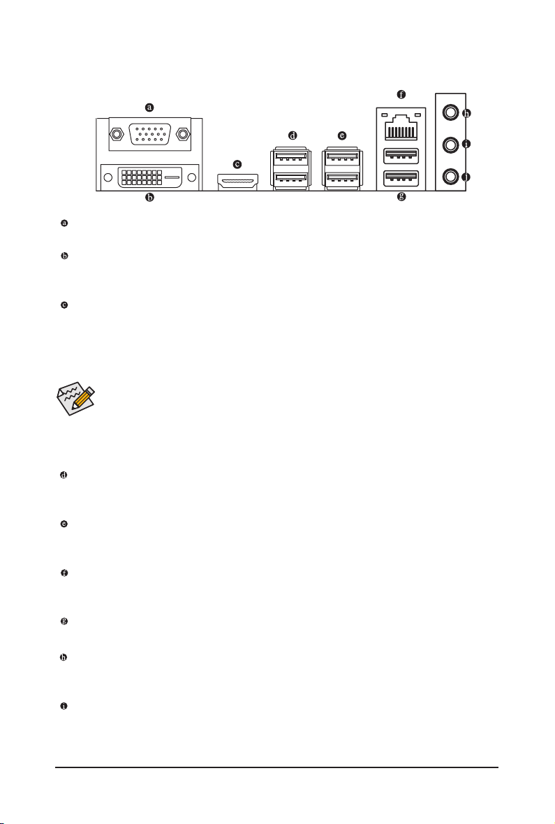
1-4 Back Panel Connectors
Video Port
The video in port allows connect to video in, which can also apply to video loop thru function.
DVI-D Port
The DVI-D port supports DVI-D specictation. Connect a monitor that supports DVI-D connectionto this
port.
HDMI Port
The HDMI (High-Denition Multimedia Interface) provides an all-digital audio/video interface to
transmit the uncompressed audio/video signals and is HDCP compliant. Connect the HDMI
audio/video device to this port. The HDMI Technology can support a maximum resolution of
1920x1200 pixel but the actual resolutions supported depend on the monitor being used.
• When After installing the HDMI device, make sure the default device for sound playback is the
HDMI device. (The item name may differ by operating system. Refer the gures below
for details.), and enter BIOS Setup, then set Onboard VGA output connect to D-SUB/
HDMI under Advanced BIOS Features..
• Please note the HDMI audio output only supports AC3, DTS and 2-channel-LPCM
formats. (AC3 and DTS require the use of an external decoder for decoding.)
USB 3.0 Port
The USB port supports the USB 3.0 specication. Use this port for USB devices such as a USB keyboard/mouse, USB printer, USB ash drive and etc.
USB 2.0 Port
The USB port supports the USB 2.0 specication. Use this port for USB devices such as a USB keyboard/mouse, USB printer, USB ash drive and etc.
RJ-45 LAN Port
The Gigabit Ethernet LAN port provides Internet connection at up to 1 Gbps data rate. The following
describes the states of the LAN port LEDs.
Line In Jack (Blue)
The default line in jack. Use this audio jack for line in devices such as an optical drive, walkman, etc.
Line Out Jack (Green)
The default line out jack. Use this audio jack for a headphone or 2-channel speaker. This jack can be
used to connect front speakers in a 4/5.1/7.1-channel audio conguration.
MIC In (Pink)
The default MIC In jack. Microphone cab be connected to MIC In jack.
- 12 - Hardware Installation

Connection/
Speed LED
LAN Port
Activity LED
State Description
Orange 1 Gb ps data rate
Green 100 Mbps data rate
Off 10 Mbps data rate
Activity LED:Connection/Speed LED:
State Description
Blinking Data transmission or receiving is occurring
Off No data tr ansmission o r receiving is oc curring
• When removing the cable connected to a back panel connector, rst remove the cable from your
device and then remove it from the motherboard.
• When removing the cable, pull it straight out from the connector. Do not rock it side to side to
prevent an electrical short inside the cable connector.
Hardware Installation - 13 -
1-5 Internal Connectors
7
4
24
5
21
20
18
22
23
17
6
9
19
10
16
11
12
8
1 2
1) F_PANEL
2) ATX
3) ATX_12V
4) F_USB2_1
5) F_USB2_2
6) F_USB2_3
7) F_AUDIO
8) SATAIII_0/1/2/3
9) COM3
10) COM4
11) COM2
12) COM1
Read the following guidelines before connecting external devices:
• First make sure your devices are compliant with the connectors you wish to connect.
• Before installing the devices, be sure to turn off the devices and your computer. Unplug the
power cord from the power outlet to prevent damage to the devices.
• After installing the device and before turning on the computer, make sure the device cable has
Hardware Installation - 14 -
been securely attached to the connector on the motherboard.
15
14
13) CPU_FAN
14) SYS_FAN
15) BATTERY
16) CLR_CMOS
17) JRS1
18) JCOMC3
19) JCOMC4
20) JRS4
21) JRS5
22) JRS3
23) JRS2
24) USB_PWR
3
13
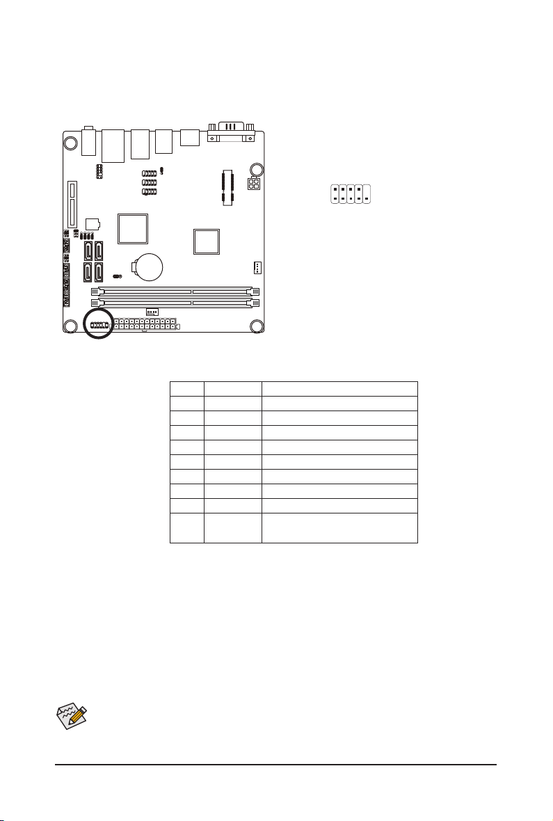
1) F_PANEL (Front Panel Header)
Connect the power switch, reset switch, speaker, LAN LED sensor and system status indicator on the
chassis to this header according to the pin assignments below. Note the positive and negative pins before connecting the cables.
2
1
Pin No. Signal Name Denition
1 HD+ Hard Disk LED Signal anode (+)
2 MPD+ Power LED Signal anode (+)
3 HD- Hard Disk LED Signal cathode(-)
4 MPD- Power LED Signal cathode(-)
5 GND Ground
6 PW+ Power Button anode (+)
7 RESET Reset Button
8 PW- Power Button cathode(-)
9 NC Reserved
10 NC No Pin
10
9
The front panel design may differ by chassis. A front panel module mainly consists of power switch,
reset switch, power LED, hard drive activity LED, speaker and etc. When connecting your chassis
front panel module to this header, make sure the wire assignments and the pin assignments are
matched correctly.
- 15 - Hardware Installation
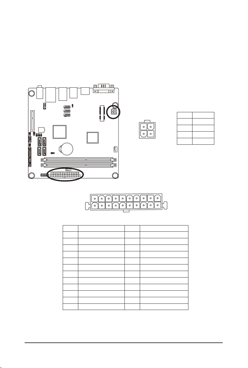
2/3) ATX/ATX_12V (2x2 12V Power Connector and 2x10 Main Power Connector)
With the use of the power connector, the power supply can supply enough stable power to all the com-
ponents on the motherboard. Before connecting the power connector, rst make sure the power supply
is turned off and all devices are properly installed. The power connector possesses a foolproof design.
Connect the power supply cable to the power connector in the correct orientation. The 12V power connector mainly supplies power to the CPU. If the 12V power connector is not connected, the computer will
not start.
ATX
Pin No. Denition
1 3.3V
2 3.3V
3 GND
4 +5V
5 GND
6 +5V
7 GND
8 Power Good
9 5VSB (stand by +5V)
10 +12V
11 +12V
12 3.3V
1
10
ATX_12V
3 4
1 2
Pin No. Denition
13 3.3V
14 -12V
15 GND
16 PS_ON
17 GND
18 GND
19 GND
20 -5V
21 +5V
22 +5V
23 +5V
24 GND
Pin No. Denition
1 GND
2 GND
3 +12V
4 +12V
12
1
- 16 - Hardware Installation

4/5/6) F_USB_1/2/3 (USB Headers)
The headers conform to USB 2.0/1.1 specication. Each USB header can provide two USB ports via an
optional USB bracket. For purchasing the optional USB bracket, please contact the local dealer.
F_USB_1
F_USB_2
F_USB_3
1
9
2
10
F_USB_1
Pin No. Denition
1 VCC
2 VCC
3 USB P0-
4 USB P1-
5 USB P0+
6 USB P1+
7 GND
8 GND
9 No Pin
10 NC
F_USB_2
F_USB_3
Pin No. Denition
1 VCC
2 VCC
3 USB P10-
4 USB P11-
5 USB P10+
6 USB P11+
7 GND
8 GND
9 No Pin
10 NC
Hardware Installation - 17 -

7) F_AUDIO (Front Panel Audio Header)
DEBUG
PORT
G.QBOFM
The front panel audio header supports Intel High Denition audio (HD) and AC'97 audio. You may connect
your chassis front panel audio module to this header. Make sure the wire assignments of the module connector match the pin assignments of the motherboard header. Incorrect connection between the module
connector and the motherboard header will make the device unable to work or even damage it.
Pin No. Denition
1 F_MIC2_L
1 2
9 10
2 GND
3 F_MIC2_R
4 -ACZ_DET
5 F_LINE2_R
6 F_MIC_JD
7 GND
8 No Pin
9 F_LINE2_L
10 F_LINE2__JD
• The front panel audio header supports HD audio by default.
• Audio signals will be present on both of the front and back panel audio connections simultaneously.
• Some chassis provide a front panel audio module that has separated connectors on each wire
instead of a single plug. For information about connecting the front panel audio module that has
different wire assignments, please contact the chassis manufacturer.
8) SATAIII_0/SATAIII_1/SATAIII_2/SATAIII_3(SATAˊGb/sConnectors)
The SATA connectors conform to SATA 6Gb/s standard and are compatible with SATA 3Gb/s standard.
Each SATA connector supports a single SATA device.
SATAIII_0
SATAIII_1
SATAIII_2
SATAIII_3
Hardware Installation - 18 -
1
7
Pin No. Denition
1 GND
2 TXP
3 TXN
4 GND
5 RXN
6 RXP
7 GND

9/10/11/12) COM3/COM4/COM2/COM1 (Serial Port Headers)
The COM headers can provide one serial port via an optional COM port cable. For purchasing the op-
tional COM port cable, please contact the local dealer.
192
COM3
COM4
COM2
COM1
10
COM1
Pin No. Denition
1 NDCDA-
2 NDSRA-
3 NSINA
4 NRTSA-
5 NSOUTA
6 NCTSA-
7 NDTDA-
8 NRIA-
9 GND
10 No Pin
COM3
Pin No. Denition
1 NDCDC-
2 NDSRC-
3 NSINC
4 NRTSC-
5 NSOUTC
6 NCTSC-
7 NDTDC-
8 NRIC-
9 GND
10 No Pin
COM2
Pin No. Denition
1 NDCDB-
2 NDSRB-
3 NSINB
4 NRTSB-
5 NSOUTB
6 NCTSB-
7 NDTDB-
8 NRIB-
9 GND
10 No Pin
COM4
Pin No. Denition
1 NDCDD-
2 NDSRD-
3 NSIND
4 NRTSD-
5 NSOUTD
6 NCTSD-
7 NDTDD-
8 NRID-
9 GND
10 No Pin
- 19 - Hardware Installation

13/14) CPU_FAN/SYS_FAN (CPU Fan/System Fan Headers)
DEBUG
PORT
The motherboard has a 4-pin CPU fan header (CPU_FAN) and a 4-pin System fan header (SYS_FAN)
header. Most fan headers possess a foolproof insertion design. When connecting a fan cable, be sure
to connect it in the correct orientation (the black connector wire is the ground wire). The motherboard
supports CPU fan speed control, which requires the use of a CPU fan with fan speed control design. For
optimum heat dissipation, it is recommended that a system fan be installed inside the chassis.
1
Pin No. Denition
1 GND
2 +12V
1
CPU_FAN
SYS_FAN
3 Sense
4 Speed Control
• Be sure to connect fan cables to the fan headers to prevent your CPU and system from
overheating. Overheating may result in damage to the CPU or the system may hang.
• These fan headers are not conguration jumper blocks. Do not place a jumper cap on the headers.
15) BATTERY (Battery)
The battery provides power to keep the values (such as BIOS congurations, date, and time information)
in the CMOS when the computer is turned off. Replace the battery when the battery voltage drops to a
low level, or the CMOS values may not be accurate or may be lost.
• Always turn off your computer and unplug the power cord before replacing the battery.
• Replace the battery with an equivalent one. Danger of explosion if the battery is replaced with an incorrect model.
• Contact the place of purchase or local dealer if you are not able to replace the battery by yourself or uncertain about the battery
model.
• When installing the battery, note the orientation of the positive side (+) and the negative side (-) of the battery (the positive side
should face up).
• Used batteries must be handled in accordance with local environmental regulations.
- 20 - Hardware Installation

16) CLR_CMOS (Clearing CMOS Jumper)
Use this jumper to clear the CMOS values (e.g. date information and BIOS congurations) and reset
the CMOS values to factory defaults. To clear the CMOS values, place a jumper cap on the two pins to
temporarily short the two pins or use a metal object like a screwdriver to touch the two pins for a few
seconds.
1
1-2 Close: Normal operation (Default setting)
2-3 Close: Clear CMOS data.
1
• After clearing the CMOS values and before turning on your computer, be sure to remove the jumper cap from
the jumper. Failure to do so may cause damage to the motherboard.
17) JRS1 (RS232/RS422/RS485 Select Headers)
- 21 - Hardware Installation
Pin No. Denition
1562
1 RXD232
2 RXD
3 RXD422
4 RXD
5 RS485
6 RXD

18/19) JCOMC3/JCOMC4 (Serial Port #3/#4 5V/12V/RI Select Headers)
1
2
1-2 Close: 5V (Power COM)
5
6
1
2
3-4 Close: RI (STAND COM)
JCOMC3
JCOMC4
5
6
1
2
5-6 Close: 12V (Power COM)
5
6
20/21/22/23) JRS4/JRS5/JRS3/JRS2 (RS232/RS422/RS485 Mode Select Jumper)
JRS2
Pin No. Denition
1 RS485_B
2 -DCD IN
3 RS232 -RXD OUT
1
JRS4
JRS3
JRS2
JRS5
JRS3
Pin No. Denition
1 RS485_A
2 -RXD IN
3 RS232 -RXD OUT
JRS4
Pin No. Denition
1 RS422_A
2 -TXD IN
3 RS232 -DTR OUT
JRS5
Pin No. Denition
1 RS422_B
2 -DTR IN
3 RS232 -DTR OUT
- 22 - Hardware Installation

USB_PWR (USB Stand-by 5V/VCC 5V Select Jumper
24)
)
1
1-2 Close: VCC 5V. (Default setting)
1
2-3 Close: Stand-by 5V.
Pin No. Denition
1 12V
2 VCC
3 Stand-by 5V
- 23 - Hardware Installation

Chapter 2 BIOS Setup
BIOS (Basic Input and Output System) records hardware parameters of the system in the CMOS on the
motherboard. Its major functions include conducting the Power-On Self-Test (POST) during system startup,
saving system parameters and loading operating system, etc. BIOS includes a BIOS Setup program that
allows the user to modify basic system conguration settings or to activate certain system features. When
the power is turned off, the battery on the motherboard supplies the necessary power to the CMOS to keep
the conguration values in the CMOS.
To access the BIOS Setup program, press the <F2> key during the POST when the power is turned on.
• BIOS ashing is potentially risky, if you do not encounter problems of using the current BIOS
version, it is recommended that you don't ash the BIOS. To ash the BIOS, do it with caution.
Inadequate BIOS ashing may result in system malfunction.
• It is recommended that you not alter the default settings (unless you need to) to prevent system
instability or other unexpected results. Inadequately altering the settings may result in system's
failure to boot. If this occurs, try to clear the CMOS values and reset the board to default values.
(Refer to the "Load Optimized Defaults" section in this chapter or introductions of the battery/
clearing CMOS jumper in Chapter 1 for how to clear the CMOS values.)
BIOS Setup Program Function Keys
<h><i> Move the selection bar to select an item
<f><g> Move the selection bar to select the screen
<Enter> Execute command or enter the submenu
<Esc> Main Menu: Exit the BIOS Setup program
Submenus: Exit current submenu
<+> Increase the numeric value or make changes
<-> Decrease the numeric value or make changes
<F1> General Help
<F2> Restore the previous BIOS settings for the current submenus
<F3> Load the Optimized BIOS default settings for the current submenus
<F4> Save all the changes and exit the BIOS Setup program
BIOS Setup - 24 -

Main
This setup page includes all the items in standard compatible BIOS.
Advanced
This setup page includes all the items of AMI BIOS special enhanced features.
(ex: Auto detect fan and temperature status, automatically congure hard disk parameters.)
Chipset
Northbridge and Southbridge additional features conguration.
Boot
This setup page provides items for conguration of boot sequence.
Security
Change, set, or disable supervisor and user password. Conguration supervisor password allows you to
restrict access to the system and BIOS Setup.
A supervisor password allows you to make changes in BIOS Setup.
A user password only allows you to view the BIOS settings but not to make changes.
Save & Exit
Save all the changes made in the BIOS Setup program to the CMOS and exit BIOS Setup. (Pressing
<F10> can also carry out this task.)
Abandon all changes and the previous settings remain in effect. Pressing <Y> to the confirmation
message will exit BIOS Setup. (Pressing <Esc> can also carry out this task.)
- 25 - BIOS Setup

2-1 The Main Menu
Once you enter the BIOS Setup program, the Main Menu (as shown below) appears on the screen. Use
arrow keys to move among the items and press <Enter> to accept or enter other sub-menu.
Main Menu Help
The on-screen description of a highlighted setup option is displayed on the bottom line of the Main Menu.
Submenu Help
While in a submenu, press <F1> to display a help screen (General Help) of function keys available for the
menu. Press <Esc> to exit the help screen. Help for each item is in the Item Help block on the right side of
the submenu.
• If you do not nd the settings you want in the Main Menu or a submenu, press <Ctrl>+<F1> to
access more advanced options.
• When the system is not stable as usual, select the Restore Defaults item to set your system to
its defaults.
• The BIOS Setup menus described in this chapter are for reference only and may differ by BIOS
version.
BIOS Setup - 26 -

BIOS Information
BIOS Vendor
Display BIOS vendor information.
BIOS Version
Display version number of the BIOS setup utility.
Core Version
Display version of the processor.
Compliency
Display compliency information.
Project Version
Display version number of the project.
BIOS Build Date and Time
Displays the date and time when the BIOS setup utility was created.
Memory Information
Total Memory
Determines how much total memory is present during the POST.
System Date
Set the date following the weekday-month-day- year format.
System Time
Set the system time following the hour-minute- second format.
- 27 - BIOS Setup

2-2 Advanced Menu
The Advanced menu display submenu options for conguring the function of various hardware components.
Select a submenu item, then press Enter to access the related submenu screen.
BIOS Setup - 28 -

2-2-1 ACPI Settings
ACPI Settings
EnableACPIAutoConguration
Enable/Disable BIOS ACPI Auto Conguration.
Option available: Enabled/Disabled. Default setting is Disabled.
ACPI Sleep State
Select the highest ACPI sleep state the system will enter, when the suspend button is pressed.
Suspend Disabled/S1 only (CPU Stop Clock)/S3 only (Suspend to RAM).
Default setting is S3 only (Suspend to RAM).
Lock Legacy Resources
When enabled (locked), this option prevents the operating system from modifying assignments for
legacy resources (serial, parallel, and PS/2 ports).
Option available: Enabled/Disabled. Default setting is Disabled.
BIOS Setup - 29 -

2-2-2 CPUConguration
BIOS Setup - 30 -

CPUConguration
PSS Support (Performance Support States/P-states Support)
Enable/Disable PSS support.
Options available: Enabled/Disabled. Default setting is Disabled.
PSTATE Adjustment
P-states level adjustment.
Options available: PState 0/PState 1/PState 2/PState 3/PState 4/PState 5/PState 6/PState 7/PState 8.
Default setting is PState 0.
NX Mode
This BIOS feature is a toggle for AMD processor's No Execute feature.
When enabled, the processor prevents the execution of code in data-only memory pages. This provides
some protection against buffer overow attacks.
When disabled, the processor will not restrict code execution in any memory area.
Options available: Enable/Disabled. Default setting is Enabled.
SVM Mode
Enable AMD CPU virtualization function. allows a single platform to run multiple operating systems in
independent hardware by decouping OS and physical hardware with hypervisor layer.
Options available: Enable/Disabled. Default setting is Enabled.
C6 Mode
Allows you to determine whether to let the CPU enter C6 mode in system halt state. When enabled,
the CPU core frequency and voltage will be reduced during system halt state to decrease power
consumption. The C6 state is a more enhanced power-saving state than C1.
Options available: Enabled/Disabled. Default setting is Enabled.
CPB Mode (Core Performance Boost)
Auto detect or disable CPB Mode.
Options available: Auto/Disabled. Default setting is Auto.
Node 0 Information
Displays the CPU L1/L2/L3 Cache information.
- 31 - BIOS Setup

2-2-3 SATAConguration
IDEConguration
OnChip SATA Type
Select the on chip SATA type.
IDE Mode: When set to IDE, the SATA controller disables its AHCI function and runs in the IDE emulation
mode.
AHCI Mode: When set to AHCI,the SATA controller enables its AHCI functionality.
Options available: IDE/AHCI/Disabled. Default setting is AHCI Mode.
SATA1/SATA2/SATA3/SATA4
The category identies Serial ATA and mSATA types of hard disk that are installed in the computer.
System will automatically detect HDD type.
Note that the specications of your drive must match with the drive table. The hard disk will not work
properly if you enter improper information for this category.
Hard drive information should be labeled on the outside device casing. Enter the appropriate option
based on this information.
BIOS Setup - 32 -

2-2-4 USBConguration
USBConguration
USB Device
Dispay the connected USB devices information.
Legacy USB Support
Enables or disables support for legacy USB devices.
Options available: Auto/Enabled/Disabled. Default setting is Enabled.
USB Mass Storage Drive Support
Enables/Disable USB Mass Storage Drive Support.
Options available: Enabled/Disabled. Default setting is Enabled.
Mass Storage Device
This BIOS feature determines if the USB ash drive be treated as a oppy disk drive or a hard drive.
Options available: Auto.
(Note)
(Note) This item is present only if you attach USB types of device.
BIOS Setup - 33 -

2-2-5 F81214FirstSuperIOConguration
BIOS Setup - 34 -

F81214FirstSuperIOConguration
SIO
Display the mode name of Super IO chip.
F81214SerialPort1/2Conguration
Press [Enter] to enter advanced meun for serial port 1 and serial port 2 settings.
Serial Port
When enabled allows you to congure the serial port settings. When set to Disabled, displays no
conguration for the serial port.
Options available: Enabled/Disabled. Default setting is Enabled.
Device Settings
Congure the Port 1/2 base I/O address and IRQ.
Options available: Auto/IO=3F8; IRQ=4/IO=3F8h; IRQ=3,4,5,6,7,10,11,12/
IO=2F8h; IRQ=3,4,5,6,7,10,11,12 /IO=3E8h; IRQ=3,4,5,6,7,10,11,12/IO=2E8h; IRQ=3,4,5,6,7,10,11,12.
Device Mode
Change Serial Port 1/2 device mode.
Options available: Serial Port Function Mode
IR Mode, Pusle 1.6us,Full Duplex/IR Mode, Pusle 1.6us,Half Duplex
IR Mode, Pusle 3/16 Bit Time, Full Duplex/IR Mode, Pusle 3/16 Bit Time, Half Duplex
BIOS Setup - 35 -

2-2-6 F81214SecondSuperIOConguration
BIOS Setup - 36 -

F81214SecondSuperIOConguration
F81214 Second Super IO Chip
Display the mode name of Super IO chip.
F81214SerialPort3/4Conguration
Press [Enter] to enter advanced meun for serial port 2 and serial port 4 settings.
Serial Port
When enabled allows you to congure the serial port settings. When set to Disabled, displays no
conguration for the serial port.
Options available: Enabled/Disabled. Default setting is Enabled.
Device Settings
Displays the Serial Port 3/4 base I/O addressand IRQ.
Device Mode
Change Serial Port 1/2 device settings.
Options available: Auto/IO=3F8; IRQ=4/IO=3F8h; IRQ=3,4,5,6,7,10,11,12/
IO=2F8h; IRQ=3,4,5,6,7,10,11,12 /IO=3E8h; IRQ=3,4,5,6,7,10,11,12/IO=2E8h; IRQ=3,4,5,6,7,10,11,12.
BIOS Setup - 37 -

2-2-7 Network Stack
Network stack
Enable/Disable the network stack (PXE and UEFI).
Option available: Enabled/Disabled. Default setting is Disabled.
BIOS Setup - 38 -

2-3 Chipset Menu
Integrated Graphics
Congure the onboard integrated graphic device.
Options available: Auto/Disabled/Force. Default setting is Auto.
UMA Frame buffer Size
Congure the UMA frame buffer size for onboard integrated graphic device.
Please note that this item appears when the Integrated Graphics is set to force.
Options available: 32M/64M/128M256M/512M/1G/2G. Default settingi is 256M.
Restore AC Power Loss
This option provides user to set the mode of operation if an AC / power loss occurs.
Power On: System power state when AC cord is re-plugged.
Power Off: Do not power on system when AC power is back.
Last State: Set system to the last sate when AC power is removed.
Options available: Power On/Power Off/Last State. Default setting is Power Off.
Azalia HD Audio
Enable/Disable onboard audio controller.
Options available: Enabled/Disabled. Default setting is Enabled.
Onboard LAN
Enable/Disable onboard LAN controller.
Options available: Enabled/Disabled. Default setting is Enabled.
LAN PXE ROM
Enable/Disable Boot Option for PXE device with option ROM.
Options available: Enabled/Disabled. Default setting is Disabled.
(Note) This item is present only when Integrated Graphics is set to Force.
(Note)
- 39 - BIOS Setup

LAN MAC Address
Display the information of LAN1 MAC address.
Erp Function
Enable/Disable Erp support function.
Options available: Enabled/Disabled. Default setting is Enabled.
SB Clock Spread Spectrum
Enable/Disable South Bridge Clock Spread Spectrum function.
Options available: Enabled/Disabled. Default setting is Enabled.
- 40 - BIOS Setup

2-3-1 SB Hardware Monitor
CPU FAN Fail Detect
Enable CPU Fan Stop Warning function.
Option available: Enabled/Disabled. Default setting is Enabled.
System FAN Fail Detect
Enable System Fan Stop Warning function.
Option available: Enabled/Disabled. Default setting is Disabled.
CPU/System Fan Speed (RPM)
Displays current CPU/System fan speed.
- 41 - BIOS Setup

2-4 Boot Menu
The Boot menu allows you to set the drive priority during system boot-up. BIOS setup will display an error
message if the drive(s) specied is not bootable.
BIOS Setup - 42 -

BootConguration
Setup Prompt Timeout
Press <+> and <-> keys to adjust the desired number.
Bootup NumLock State
Allows you to select power-on state for NumLock function.
Options available: On/Off. Default setting is On.
Quiet Boot
This BIOS feature determines if the BIOS should hide the normal POST message with the motherboard
or system manufacturer's full-screen.
When it is enabled, the BIOS will display the full-screen logo during the boot-up sequence, hiding normal
POST message.
When it is disabled, the BIOS will display the normal POST messages, instead of the full-screen logo,
Options available: Enabled/Disabled. Default setting is Disabled.
Fast Boot
If enabled, the system will speed the boot up time.
Options available: Enabled/Disabled. Default setting is Enabled.
• The following four items appears and congurable when the Fast Boot is set to Enabled.
VGA Support
All VGA devices will not be available until OS boot up for a fastest POST time.
Options available: Enabled/Disabled. Default setting is Enabled.
USB Support
All USB devices will not be available until OS boot up for a fastest POST time.
Options available: Enabled/Disabled. Default setting is Enabled.
PS2 Devices Support
The PS/2 keyboard and mouse devices will not be available until OS boot up for a fastest POST time.
Options available: Enabled/Disabled. Default setting is Enabled.
Network Stack Drive Support
When enabled, the system will load the network stack driver during POST.
When disabled, the system will skip the network stack driver from loading during POST.
Options available: Enabled/Disabled. Default setting is Disabled.
Boot Option Priorities
Boot Option #1/2/3
Press Enter to congure the boot priority.
Hard Drive BBS Priorities
Press Enter to congure the boot priority.
- 43 - BIOS Setup

2-4-1 CSM parameters
CSM parameters
Press Enter to congure the advanced items.
Launch
CSM (Compatibility Support Module)
Enable/Disable Compatibility Support Module (CSM) launch.
Options available: Enabled/Disabled. Default setting is Enabled.
• The following ve items appears and congurable when the Launch CSM is set to Enabled.
• If the Launch CSM is set to Disabled, the following ve items will not be able to support Legacy
mode.
Bootoptionlter
Determines which devices system will boot to.
Options available: UEFI and Legacy/Legacy only/UEFI only. Default setting is UEFI and Legacy.
Launch PXE OpROM policy
Determines which devices system will boot to.
Options available: Do not launch/UEFI only/Legacy only/Legacy rst/UEFI rst. Default setting is
Do not launch.
Launch Storage OpROM policy
Determines which devices system will boot to.
Options available: Do not launch/UEFI only/Legacy only/Legacy rst/UEFI rst. Default setting is Legacy
only.
Launch Video OpROM policy
Determines which devices system will boot to.
Options available: Do not launch/UEFI only/Legacy only/Legacy rst/UEFI rst. Default setting is Legacy
only.
- 44 - BIOS Setup

Other PCI device ROM priority
For PCI devices other than Network, Mass storage or Video device, denes which OpROM to launch.
Options available: UEFI OpROM/Legacy OpROM. Default setting is UEFI OpROM.
- 45 - BIOS Setup

2-5 Security Menu
The Security menu allows you to safeguard and protect the system from unauthorized use by setting up access passwords.
There are two types of passwords that you can set:
• Adminstrator Password
Entering this password will allow the user to access and change all settings in the Setup Utility.
• User Password
Entering this password will restrict a user’s access to the Setup menus. To enable or disable
this eld, a Administrator Password must rst be set. A user can only access and modify the
System Time, System Date, and Set User Password elds.
AdministratorPassword
Press Enter to congure the Administrator password.
User Password
Press Enter to congure the user password.
BIOS Setup - 46 -

2-5-1 Secure Boot menu (Optional)
The Secure Boot Menu appears when your device is installed the Windows® 8 operatin system.
Secure Boot menu
Platform Mode
Display the System Platform Mode State.
Secure Boot
Display the status of Secure Boot.
Secure Boot Control
Enable/Disable Secure Boot function.
Options available: Enabled/Disabled. Default setting is Enabled.
Secure Boot Mode
Secure Boot requires all the applications that are running during the booting process to be pre-signed
with valid digital certicates. This way, the system knows all the les being loaded before Windows 8
loads and gets to the login screen have not been tampered with.
When set to Standard, it will automatically load the Secure Boot keys form the BIOS databases.
When set to Custom, you can customize the Secure Boot settings and manually load its keys from the
BIOS database.
Options available: Standard/Custom. Default setting is Standard.
BIOS Setup - 47 -

2-5-1-1 Image Execution policy
Internal FV
Image Execution Policy per device path on Security Violation.
Options available: Always Execute/Always Deny/Allow Execute/Defer Execute/ Deny Execute/ Query
User. Default setting is Deny Execute.
Option ROM
Image Execution Policy per device path on Security Violation.
Options available: Always Execute/Always Deny/Allow Execute/Defer Execute/ Deny Execute/ Query
User. Default setting is Deny Execute.
Removable Media
Image Execution Policy per device path on Security Violation.
Options available: Always Execute/Always Deny/Allow Execute/Defer Execute/ Deny Execute/ Query
User. Default setting is Deny Execute.
Fixed Media
Image Execution Policy per device path on Security Violation.
Options available: Always Execute/Always Deny/Allow Execute/Defer Execute/ Deny Execute/ Query
User. Default setting is Deny Execute.
BIOS Setup - 48 -

2-5-1-2 Key Management
Key Management
This item appears only when the Secure Boot Mode is set to Custom.
Factory Default Key Provisioning
Force the system to Setup Mode. This will clear all Secure Boot Variables such as Platform Key (PK),
Key-exchange Key (KEK), Authorized Signature Database (db), and Forbidden Signaures Database (dbx).
Options available: Enabled/Disabled. Default setting is Disabled.
Platform Key (PK)
Display the status of Platform Key.
Set new PK
Press [Enter] to congure a new PK.
Delete PK
Press [Enter] to delete the existed PK. Once the PK is deleted, all the system's Secure Boot keys will not
be activated.
Key Exchange Key Database (KEK)
Display the status of Platform Key.
Set new KEK
Press [Enter] to congure a new KEK.
Delete KEK
Press [Enter] to delete the KEK from your system.
Append Var to KEK
Press [Enter] to load additional KEK from a storage devices for an additional db and dbx management.
BIOS Setup - 49 -

Authorized Signature Database (DB)
Display the status of Authorized Signature Database.
Set new DB
Press [Enter] to congure a new db.
Delete DB
Press [Enter] to delete the db from your system.
Append Var to DB
Press [Enter] to load additional db from a storage devices.
Forbidden Signature Database (DBX)
Display the status of Forbidden Signature Database.
Set new DB
Press [Enter] to congure a new dbx.
Delete DB
Press [Enter] to delete the dbx from your system.
Append Var to DB
Press [Enter] to load additional db from a storage devices.
Save Secure Boot Keys
Press [Enter] to store content of each Secure Boot Variable.
BIOS Setup - 50 -

2-6 Save & Exit Menu
The Exit menu displays the various options to quit from the BIOS setup. Highlight any of the exit options then
press Enter.
Save Changes and Exit
Saves changes made and close the BIOS setup and exit system setup.
Options available: Yes/No.
Discard Changes and Exit
Discards changes made and close the BIOS setup and exit system setup .
Options available: Yes/No.
Save Changes and Reset
Active this option to reset system after saving the changes.
Options available: Yes/No.
Discard Changes and Reset
Active this option to reset system after without saving any changes.
Options available: Yes/No.
Save Changes
Active this option to save all the changes.
Discard Changes
Discards changes made and close the BIOS setup.
Restore Defaults
Press <Enter> on this item and then press the <Y> key to load the default BIOS settings.
Options available: Yes/No.
- 51 - BIOS Setup

Save as User Defaults
Press <Enter> on this item and then press the <Y> key to save as user default settings.
Options available: Yes/No.
Restore User Defaults
Press <Enter> on this item and then press the <Y> key to restore user default settings.
Options available: Yes/No.
Boot Override
Press Enter to congure the device as the boot-up drive.
UEFI: Built-in in EFI Shell
Press <Enter> on this item to Launch EFI Shell from lesystem device.
BIOS Setup - 52 -
 Loading...