

Page 1

Page 2

FCC Complicance Statement / FCC 聲明
For Users in the USA
This equipment has been tested and found to comply with the limits
for a Class B digital device, pursuant to Part 15 of FCC Rules. These
rules are designed to provide reasonable protection against harmful
interference when the equipment is operated in a residential
installation. This equipment generates, uses, and can radiate radio
frequency energy, and if not installed a nd used in acc orda nce with the
installation, may cause harmful interference to radio communications.
However, there is no guarantee that interference will not occur in
a particular installation. If this equi pment does cause harmful
interference to radio or television reception, which can be determined
by turning the equipment off and on, you are encouraged to try to
correct the interference by one or more of the following measures:
Reorient the receiving antenna.
Increase the separation between the equipment and receiver.
Connect the equipment into an outlet on a circuit different from
that to which the receiver is connected.
Consult the dealer or an experienced radio/TV technician for
help.
Notes:
Unauthorized changes or modifications may void the user's right to operate the
equipment.
Only equipment certified to comply with Class B (computer input/output devices,
terminals, printers, etc.) should be attached to this equipment and all such
equipment must be connected with shielded interface cable.
Page 3

Preface / 前言
Thank you for purchasing and adopting the SB Series as your favorite computer
product. To assure the safe application of this product, please carefully read the
following:
感謝您採購與愛用 MB 系列電腦產品。為確保您能安全地使用本產品,請您仔細閱讀以下說明:
Please strictly follow the labeled warnings and instructions given.
請務必遵守產品中的標示警告及指示。
Before disassembling or cleaning this product, make sure the power
connector is unplugged.
拆卸及清理本產品前,切記拔掉電源插頭。
Never wipe the interior of the system with water or dip the system in water.
在任何情況下,請勿用水擦拭機器內部或浸濕機體。
Before connecting to any peripheral, please turn off the power of the system.
連接或組裝任何週邊設備前,請先關閉電源。
Ensure that the voltage select switch is in the correct position for the type of
voltage you use (115V/230V). If you are not sure which kind of voltage you
are using, please contact your dealer.
本產品須使用標示上所指定的電源種類,如果您不確定使用何種電源,請與您的經銷商
聯絡。
July / 2004
If the battery is not properly handled, there may be a risk of
WARNING / 警告
explosion; make sure you are using the same or equivalent battery.
Please dispose the used battery according to the instructions given
by the manufacturer.
電池若處理不當,可能有爆炸的危險。替換時請務必使用相同或同等的電池。
請依據製造商指示處理廢棄電池。
☞ Please be aware that cracked, deeply scratched or other poor
quality disk used in this drive may cause damage to the drive and
data in the disk. Such discs may break at high speed rotation. If full
care is not exercised in relation to this matter you may void the
warranty to this product.
請注意:若於本光碟機使用破裂、嚴重刮傷或其他劣質光碟片,可能導致機器
損壞或資料流失。請小心使用機器,如因不當操作或使用劣質光碟片而造成機
器損壞,將可能導致保固失效。
Page 4

Items included in the package / 系統包裝說明圖
Power
Cord
/ 電源線
Software & Manual /
程式光碟與使用手冊
0 Specification with “Option” are subject to change without notice.
以”*”所標示的規格與實際產品有差異時,以實際出貨產品為準。
*Mouse (Option) /
滑鼠(選購)
*Keyboard (Option)
/ 鍵盤(選購)
PC / 主機
Other Product Specifications / 其他產品規格
- Micro ATX chassis / Micro ATX 電腦外殼
- Micro ATX main board of GIGABYTE / 技嘉之 Micro A TX 主機板
- Power Supply / 電源供應器
- DVD-ROM / CD-ROM / Optical Device Drives / DVD-ROM / CD-ROM /(選購)
- 3.5” 1.44MB FDD / 3.5” 1.44MB 軟碟機
- Card Reader (Option) / 讀卡機(選購)
- Assembly Box Content / (附件盒)
①Cable Tie / 束線帶 ②Scre w bag / 螺絲包
Page 5

I. Chassis / 電腦機殼
Dimension= 350(D)mm x 195(W)mm x 370(H)mm
外觀尺寸= 350(D)mm x 195(W)mm x 370(H)mm
This chassis is made with material complied with UL specification. There are two
5.25” and four 3.5” drive bays. This chassis complies with corresponding EMC
and safety regulations.
本電腦機殼採用通過 UL 規格之材料,可裝置兩個 5.25”及四個 3.5”的存取設備。本電腦機
殼的設計兼具電磁波防制及電腦安全規格之需求。
II. Motherboard / 主機板
See Motherboard Manual for details.
關於本系統配備之主機板規格及相關介紹,請見主機板使用手冊。
III. Power Supply / 電源供應器
The ATX switching power supply included with this product supports soft off
function. Hence, the system can be shut down automatically. Default input
voltage setting is 230V.
本產品採用 A.T.X 電源供應器,支援軟體關機功能。出廠電壓預設值為 230V。
0 Note: Please check the voltage requirements in the country you reside
before turning on the PC. Select the correct voltage setting for your local
area voltage before the computer system is plug to the power source.
注意:開機前請先確認各國的電壓預設值。請在接上電源前先確定是否已將電壓開關設
定為 115V。
WARNING: Select incorrect setting will cause the Power
supply failure!
警告:若開關設定錯誤,可能導致電源供應器毀損!
Page 6
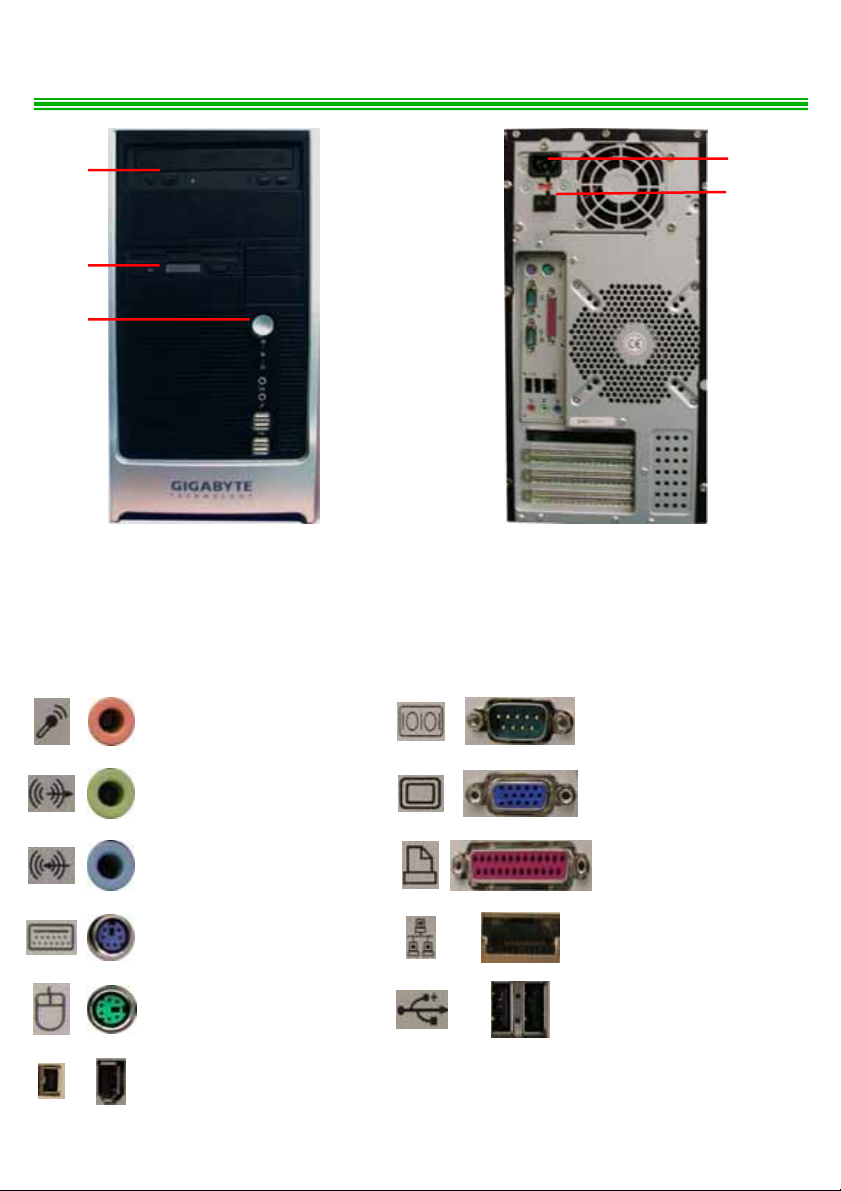
IV. Front and Rear Panel Components / 前後面板的裝置
➀
➁
➂
Front & Rear Panel Components / 前後面板圖
1. DVD-ROM (Option) / 光碟機(選購)
2. Floppy Disc (Option) / 軟碟機(選購)
3. Power Button / 電源按鈕
I/O Ports / 輸出入埠
MIC In / 麥克風
➃
➄
4. AC Inlet / 電源接頭
5. Voltage Switch / 電壓開關
COM Port / 串列埠
Line Out (Audio Out or
Earphone)
Line In (Audio In) / 音源輸入
Keyboard Port (PS/2)
鍵盤孔(PS/2)
Mouse Port (PS/2)
滑鼠埠(PS/2)
IEEE 1394 / IEEE 1394 插座
/ 音源輸出 (耳機)
VGA Port / VGA埠
LPT Port / 並列埠
LAN Port / 網路埠
USB Port / USB埠
Page 7

V. Installing the System / 系統設備安裝
1. Remove the screws of both side covers of the chassis, push backward to dismount
the covers.
將機殼後方側板的螺絲卸下,並將兩片側板向後推出。
2. Remove 3 screws of the disc drive chassis and dismount chassis.
卸下磁碟機支架上的 3 顆螺絲,並取出磁碟機支架。
Page 8

3. Memory / 記憶體
There are fixing grooves on both sides / 兩側有固定凹槽
DDR
Make sure the direction of the foolproof groove must be the same as that of the
memory slot on the motherboard. The hooks must be fixed into the grooves before the
installation is considered complete.
安裝主機板上的記憶體插槽時,其方向必須與防呆凹槽的方向相同才能順利安裝。請務必將卡勾固
定在凹槽上,才是正確安裝的方式。
4. HDD / FDD /ODD Installation / 安裝硬碟機/軟碟機/選購光碟機
4-1. There are four 3.5” drive bays in the disc drive chassis. The left 2 bays are for FDD,
and the right 2 bays are for HDD. Select a place and fix the HDD / FDD with
screws.
本磁碟機支架可擴充 4 個 3.5”的儲存裝置。左側兩槽專供軟碟機使用,右側兩槽則供硬碟機
使用。請在選定位置後將硬碟機/軟碟機放入支架中,並對準螺絲孔位鎖上螺絲。
Page 9

n o p q n( o(( p( q n( o( p q(
((
Put HDD into the
disc driver chassis
將硬碟機放入磁碟機支架中
0 Note: Bay
n and o are for FDD. Bay p and q are for HDD.
Put FDD into the
disc driver chassis
將軟碟機放入磁碟機支架中
注意:n、o槽專供軟碟機使用。p、q槽專供硬碟機使用。
4-2. Put the ODD (DVD-ROM / CD-ROM) into the rack of front panel, align the screws
at the screw holes of the rack.
將您所選購的光碟機 (DVD-ROM / CD-ROM) 放入前面板支架中,並對準支架的螺絲孔位
鎖上螺絲。
Align the screws at
the screw holes
鎖上螺絲
Page 10

4-3. T ake out the IDE / FDD bus cables bundled in the accessory kit. Connect the black
connector to the hard disk drive and floppy disk drive / option devices, and to the
corresponding locations in the motherboard. Align the first pin of the red
Pin 1 labeled on the hard disk and floppy disk / option devices, also to Pin 1
labeled on the corresponding locations in the motherboard.
取出附件盒內的 IDE 匯流排排線,將排線兩端的黑色連接頭分別連接於硬碟及軟碟機/選購光
碟機,以及前述裝置在主機板上的對應位置。請將排線上有紅色標示
及軟碟機/選購光碟機上標示為 1 的腳位,以及主機板對應位置上標示為 1 的腳位。
的第一腳分別對齊硬碟
cable to
Fix the HDD cable to
motherboard
將硬碟機排線接至主機板
Fix the HDD cable to HDD
將硬碟機排線接至硬碟機
0 Note: If the first pin of the red
hard disk and floppy disk drive / option devices, your hard disk and floppy
disk drive / option devices will not work and may cause damage to the disk.
注意:若您未將連接線上有紅色標示
1 的腳位,您的硬碟及軟碟機/選購光碟機將無法啟動且可能導致損壞。
Fix the FDD cable to
motherboard
將軟碟機排線接至主機板
Fix the FDD cable to FDD
將軟碟機排線接至軟碟機
cable doesn’t align to Pin 1 labeled on th e
的第一腳對齊硬碟及軟碟機/選購光碟機上標示為
Fix the ODD cable to
motherboard
將光碟機排線接至主機板
Fix the ODD cable to ODD
將光碟機排線接至光碟機
Page 11

4-4. Connect the connector of the power supply to the power supply socket of the hard
disk drive and floppy disk drive / option device. When you finished, align the disc
drive chassis back with screws. Follow above note.
請將電源供應器上的電源接頭連接到硬碟及軟碟機/選購光碟機上的電源插座。當您完成後,
請將磁碟機支架以螺絲鎖回原處。注意事項同前。
Fix the HDD cable to HDD
將硬碟機排線接至硬碟機
5. CPU / 中央處理器
5-1. Evenly spread the heat dispersion paste on the CPU and make sure it totally
covers the CPU. Insert the CPU on the CPU socket. Make sure that you have lifted
the transversal lever and aligned the aslant side of the CPU along the aslant side
of the CPU socket.
將散熱膏均勻塗抹在 CPU 上,並確保完全覆蓋住 CPU。將 CPU 置於主機板上的 CPU 插座。
請務必將橫桿拉起,並將 CPU 斜邊處與 CPU 插座的斜邊處對齊。
A. For LGA 755 processors / 安裝 LGA 755 處理器
Fix the FDD cable to FDD
將軟碟機排線接至軟碟機
Fix the ODD cable to ODD
將光碟機排線接至光碟機
Evenly spread the heat dispersion paste
on the CPU / 將散熱膏均勻塗抹於 CPU 上
B. For Socket 478 processors / 安裝 Socket 478 處理器
CPU Pin
Evenly spread the heat dispersion paste
on the CPU / 將散熱膏均勻塗抹於 CPU 上
Lift the transversal lever / 拉起橫桿
Lift the
transversal
lever
拉起橫桿
Page 12

5-2. After CPU is secured tightly onto the CPU socket, release the transversal lever and
attach it to the CPU socket The CPU fan must be tightly attached on the CPU to
maximize the effect of heat dispersion. Connect fan power connector to CPU FAN
on the motherboard.
當CPU 與插座已完全密合後,請將橫桿放下並勾緊 CPU 插座。組裝 CPU 風扇時必須將風扇
盡可能貼緊 CPU,以達最佳散熱效果。將 CPU 風扇接頭連接到主機板上標示為 CPU FAN 處。
A. For LGA 755 processor / 安裝 LGA 755 處理器
Connect the cooler power connector to CPU FAN on the motherboard
將 CPU 風扇接頭連接到主機板上標示為 CPU FAN處
B. For Socket 478 processors / 安裝 Socket 478 處理器
Click the heat sink locker to
the motherboard retention
module.
將風扇卡勾固定在風扇支架上
Install fan on top of CPU / 將 CPU 風扇放在 CPU 上
Press the 4
black tubes
on cooler to
fix it on the
rank / 將風扇
上的四個黑色
短管壓下,好將
風扇固定在
CPU 上
0 When connecting the cooler power connector, please locate a 4-pins socket
next to the “CPU FAN” mark on motherboard.
連接風扇接頭時,主機板上標示”CPU FAN”字樣旁的4 針插座即為風扇接頭連接處。
■ Other Instructions / 其他注意事項
For those models with front audio module:
系統已安裝前方USB+音源模組者:
If you use microphone for recording, please insert it in the Front Audio Port.
若您要使用麥克風錄音,請將麥克風連接至前方的麥克風插孔。
 Loading...