How it Works
Log In / Sign Up
Buy Points
How it Works
FAQ
Contact Us
Questions and Suggestions
Users
Gigabyte
Loading...
G
GZ-AA1CB-SNB
GZ-AA1CB-SNG
GZ-AA1CB-SNS
GZ-AA2CB-SNB
GZ-AA2CB-SNG
GZ-AA2CB-SNS
GZ-AA3CB-SJB
GZ-AA3CB-SJS
GZ-AABC61-CNB Black
GZ-FADA51-CJB
GZ-FAEA41-CJB
GZ-FSCA1-AN
GZ-FSCA1-SN
GZ-FW1CA-AJS
GZ-KX1
GZ-KX5
3
GZ-KX9
GZ-KXA
GZ-X1
GZ-X2
GZ-X3
GZ-X4
GZ-X5
GZ-X6
GZ-X7
GZ-X8
GZ-X9
GZ-XX1CA-SNS
H
H110TN-ZM
H231-G20
H252-Z12
H261-NO0
H261-PC0
H310 D3
H310M A
H310M A 2.0
H310M D3H
H310M DS2
H310M DS2 2.0
H310M H
2
H310M H 2.0 (rev. 1.0)
H310M HD3 2.0
H310M M.2 2.0
2
H310M S2 2.0 (rev. 1.0)
H310M S2H
H310M S2H 2.0
H310M S2P
H310M S2V
H310M S2V 2.0 (rev. 1.0)
H310N
H310N 2.0
H370 AORUS GAMING 3
H370 Aorus Gaming 3 WIFI
H370 HD3
H370M D3H GSM
H370M DS3H
H410M DS2V V2
H410M H
H410M H V2
2
H410M S2
H410M S2H
H410M S2H V2
H410M S2 V2
H470 Aorus Pro AX
H470 HD3
H470I Aorus Pro AX
H470M DS3H
H510M DS2V
H510M H
2
H510M H V2
H510M K V2
H510M S2H
H510M S2H V3
H510M S2 V2
H55M-S2
H610I DDR4
H610M H
H610M H V2 DDR4
H610M K DDR4
2
H610M S2H
H610M S2H V2 DDR4
H61M-S1
H61M-S2PV
2
H663
H663-RH
H81
H81M-DS2
H81M-S2PV
H971
2
H971-RH
HA-91
3
HAKATA
HAKATA_FRONT
I
I1320
2
I1520M
2
I1520N
3
i1520 Series
i3140
i350
I915P-A7 combo
Loading...
Loading...
Nothing found
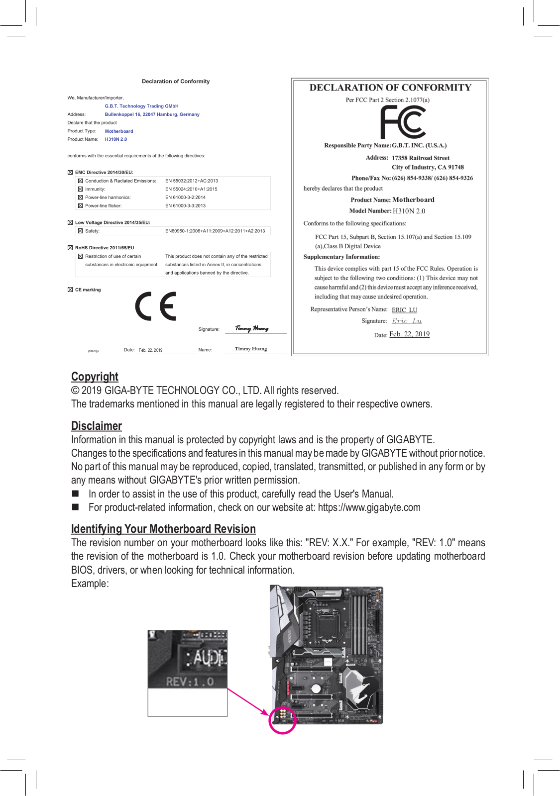
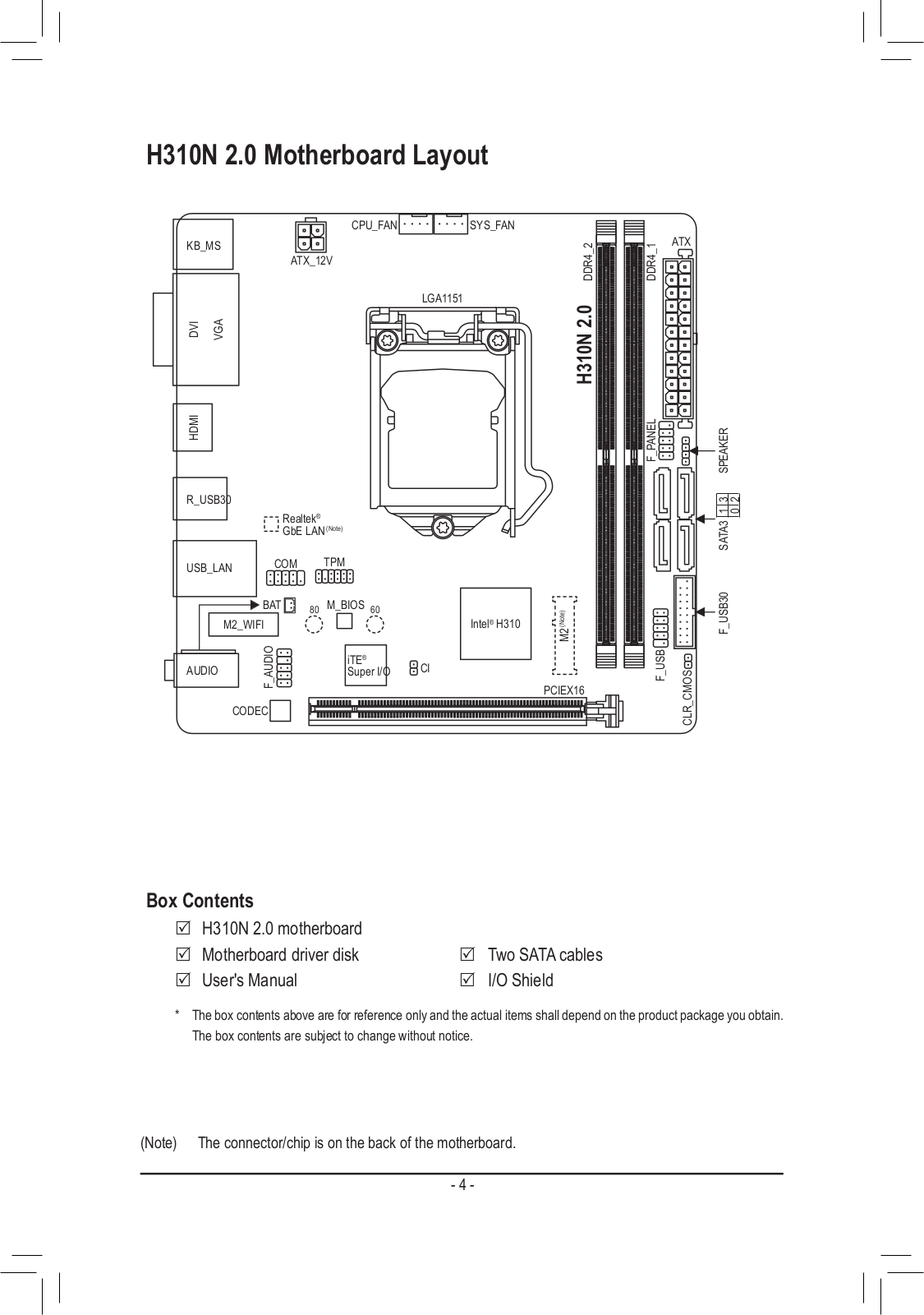
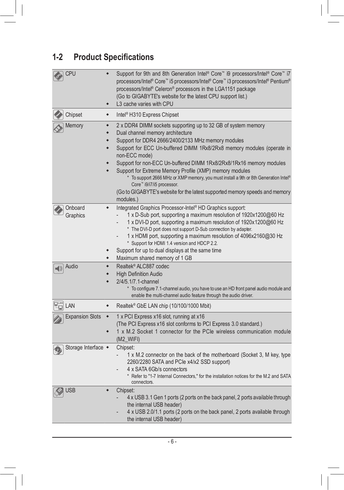
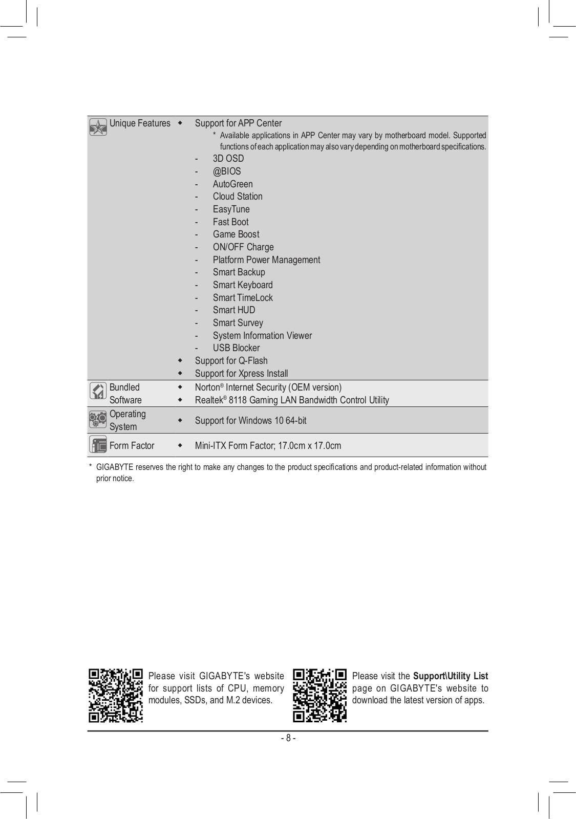
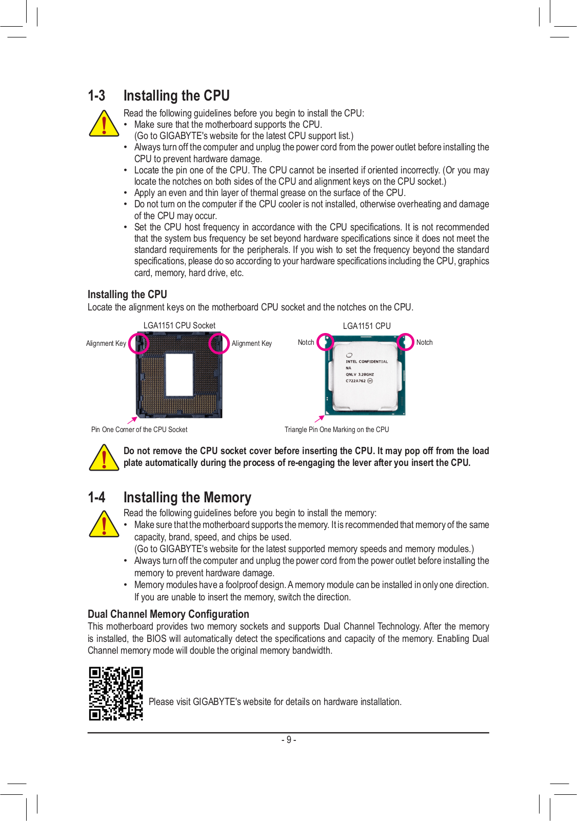
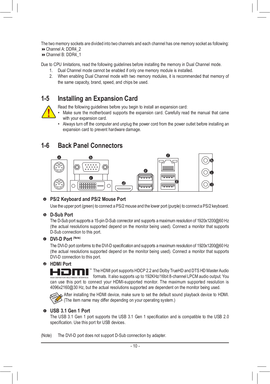
H310N 2.0
operation manual
40 pgs
11.07 Mb
1
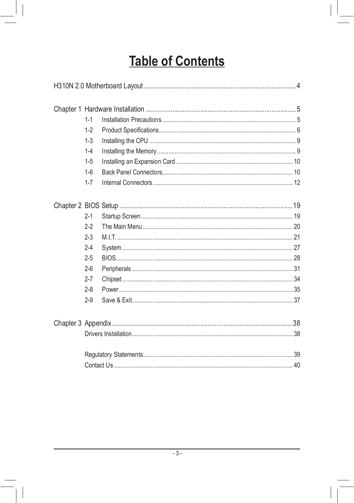
Table of contents
Loading...
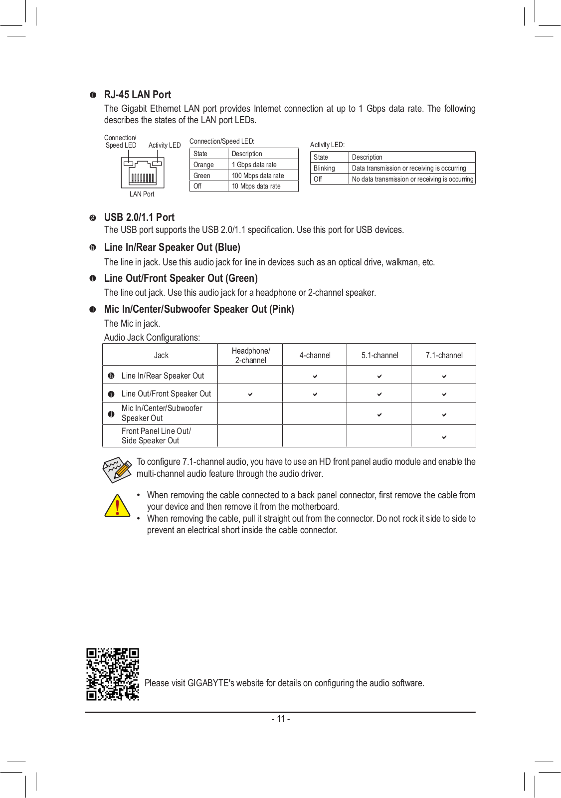
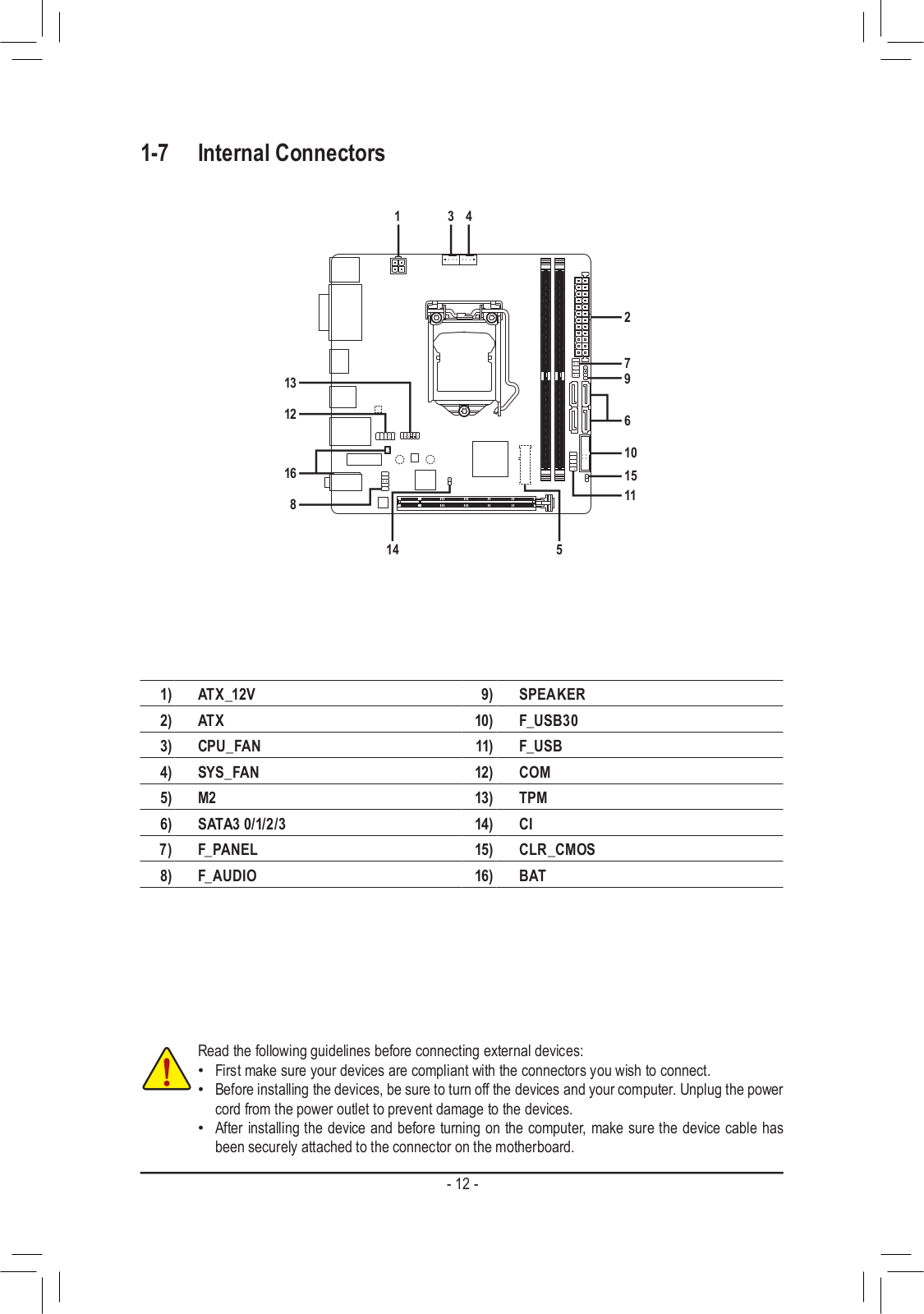
Gigabyte H310N 2.0 operation manual
...
Gigabyte operation manual
Download
Specifications and Main Features
Frequently Asked Questions
User Manual
Download
Loading...
+
hidden pages
Unhide
You need points to download manuals.
1 point = 1 manual.
You can buy points or you can get point for every manual you upload.
Buy points
Upload your manuals