

Page 1

H261-NO0
H261-PC0
HCI Server – Intel DP 2U 4 Nodes Server
User Manual
Rev. 1.0
Page 2

Copyright
© 2019 GIGA-BYTE TECHNOLOGY CO., LTD. All rights reserved.
The trademarks mentioned in this manual are legally registered to their respective owners.
Disclaimer
Information in this manual is protected by copyright laws and is the property of GIGABYTE.
Changes to the specications and features in this manual may be made by GIGABYTE without prior
notice. No part of this manual may be reproduced, copied, translated, transmitted, or published in any
form or by any means without GIGABYTE's prior written permission.
Documentation Classications
In order to assist in the use of this product, GIGABYTE provides the following types of documentation:
User Manual: detailed information & steps about the installation, conguration and use this
product (motherboard), covering hardware & BIOS
Service Guide: detailed information & steps about the installation, conguration and use of
this product (server barebones), covering hardware & BIOS
User Guide: information about a particular rmware or software package that can be used
with this product (such as BMC rmware)
Quick Installation Guide: a short guide with visual diagrams that you can reference easily for
installation purposes
Please see the support section of the online product page to check the current availability of these documents
For More Information
For related product specications, the latest rmware and software, and related information, please visit our
website at:
http://www.gigabyte.com
For GIGABYTE distributors and resellers, additional sales & marketing materials are available from our re-
seller portal:
http://reseller.b2b.gigabyte.com
- 2 -
Page 3

Conventions
The following conventions are used in this user's guide:
NOTE!
Pieces of additional
information related to the current topic.
CAUTION!
Precautionary measures to
avoid possible hardware or software problems.
WARNING!
Alerts to any damage that might
result from doing or not doing specic actions.
Page 4
Server Warnings and Cautions
Before installing a server, be sure that you understand the following warnings and cautions.
WARNING!
To reduce the risk of electric shock or damage to the equipment:
• Do not disable the power cord grounding plug. The grounding plug is an important safety
feature.
• Plug the power cord into a grounded (earthed) electrical outlet that is easily accessible at all
times.
• Unplug the power cord from the power supply to disconnect power to the equipment.
• Do not route the power cord where it can be walked on or pinched by items placed against it.
Pay particular attention to the plug, electrical outlet, and the point where the cord extends from
the server.
WARNING!
To reduce the risk of personal injury from hot surfaces, allow the drives and the internal
system components to cool before touching them.
WARNING!
This server is equipped with high speed fans. Keep away from hazardous moving fan
blades during servicing.
CAUTION!
• Do not operate the server for long periods with the access panel open or removed. Operat-
ing the server in this manner results in improper airow and improper cooling that can lead to
thermal damage.
• Danger of explosion if battery is incorrectly replaced.
• Replace battery with the same or equivalent type recommended by the manufacturer.
• Dispose of used batteries according to the manufacturer’s instructions.
CAUTION!
Risk of explosion if battery is replaced incorrectly or with an incorrect type. Replace the battery
only with the same or equivalent type recommended by the manufacturer. Dispose of used batteries according to the manufacturer’s instructions.
Page 5

Electrostatic Discharge (ESD)
CAUTION!
ESD CAN DAMAGE DRIVES, BOARDS, AND OTHER PARTS. WE RECOMMEND THAT YOU
PERFORM ALL PROCEDURES AT AN ESD WORKSTATION. IF ONE IS NOT AVAILABLE,
PROVIDE SOME ESD PROTECTION BY WEARING AN ANTI-STATIC WRIST STRAP ATTACHED TO CHASSIS GROUND -- ANY UNPAINTED METAL SURFACE -- ON YOUR SERVER
WHEN HANDLING PARTS.
Always handle boards carefully, they can be extremely sensitive to ESD. Hold boards only by
their edges without touching any components or connectors. After removing a board from its
protective ESD bag or from the system, place the board component side up on a grounded, static
free surface. Use a conductive foam pad if available but not the ESD bag. Do not slide the board
over any surface.
System power on/off: To service components within the server, please ensure the power has
been disconnected.
e.g. Remove the node from the server chassis (to disconnect power) or disconnect the power
from the server chassis.
Make sure the system is removed from the rack before opening the chassis, adding, or removing
any non hot-plug components.
Hazardous conditions, devices and cables: Hazardous electrical conditions may be present
on power, telephone, and communication cables. Turn off the system chassis and disconnect the
cables attached to the system before servicing the chassis. Otherwise, personal injury or equip-
ment damage can result.
Electrostatic discharge (ESD) and ESD protection: ESD can damage drives, boards, and
other parts. We recommend that you perform all procedures in this chapter only at an ESD work-
station. If one is not available, provide some ESD protection by wearing an antistatic wrist strap
attached to chassis ground (any unpainted metal surface on the server) when handling parts.
ESD and handling boards: Always handle boards carefully. They can be extremely sensi-tive to
electrostatic discharge (ESD). Hold boards only by their edges. After removing a board from its
protective wrapper or from the system, place the board component side up on a grounded, static
free surface. Use a conductive foam pad if available but not the board wrapper. Do not slide
board over any surface.
Page 6

Installing or removing jumpers: A jumper is a small plastic encased conductor that slips over
two jumper pins. Some jumpers have a small tab on top that can be gripped with n-gertips or
with a pair of ne needle nosed pliers. If the jumpers do not have such a tab, take care when us-
ing needle nosed pliers to remove or install a jumper; grip the narrow sides of the jumper with the
pliers, never the wide sides. Gripping the wide sides can dam-age the contacts inside the jumper,
causing intermittent problems with the function con-trolled by that jumper. Take care to grip with,
but not squeeze, the pliers or other tool used to remove a jumper, or the pins on the board may
bend or break.
Page 7

Table of Contents
Chapter 1 Hardware Installation ...................................................................................11
1-1 Installation Precautions .................................................................................. 11
1-2 Product Specications .................................................................................... 12
1-3 System Block Diagram ................................................................................... 18
Chapter 2 System Appearance ..................................................................................... 19
2-1 Front View ...................................................................................................... 19
2-2 Rear View ....................................................................................................... 20
2-3 Front Panel LED and Buttons ........................................................................ 21
2-4 Rear System LAN LEDs ................................................................................. 22
2-5 Hard Disk Drive LEDs .................................................................................... 23
2-6 Power Supply LED Behavior .......................................................................... 24
Chapter 3 System Hardware Installation ......................................................................25
3-1 Installing the Hard Disk Drive ......................................................................... 26
3-2 Removing the Node ....................................................................................... 27
3-3 Removing Chassis Cover ............................................................................... 28
3-4 Removing and Installing the Fan Duct ........................................................... 29
3-5 Removing and Installing the Heatsink ............................................................ 30
3-6 Installing the CPU .......................................................................................... 32
3-7 Installing Memory ........................................................................................... 34
3-7-1 Six Channel Memory Conguration ........................................................................34
3-7-2 Installing the Memory ............................................................................................35
3-7-3 DIMM Population Table ..........................................................................................35
3-8 Installing the PCI Expansion Card ................................................................. 36
3-9 Installing the OCP Card ................................................................................. 38
3-10 Replacing the Fan Assembly .......................................................................... 39
3-11 Replacing the Power Supply .......................................................................... 40
3-11-1 Power Supply LED Behavior ..................................................................................41
3-12 Replacing Power Distribution Board Cage ..................................................... 42
3-13 Cable Routing ................................................................................................43
3-13-1 H261-NO0 ..............................................................................................................43
3-13-2 H261-PC0 ...............................................................................................................48
Chapter 4 Motherboard Components ...........................................................................51
4-1 Motherboard Components ............................................................................. 51
4-2 Jumper Setting .............................................................................................. 52
- 7 -
Page 8

Chapter 5 BIOS Setup ..................................................................................................53
5-1 The Main Menu .............................................................................................. 55
5-2 Advanced Menu ............................................................................................. 58
5-2-1 Trusted Computing .................................................................................................59
5-2-2 Serial Port Console Redirection .............................................................................60
5-2-3 SIO Conguration ...................................................................................................64
5-2-4 PCI Subsystem Settings .........................................................................................65
5-2-5 USB Conguration ..................................................................................................66
5-2-6 Post Report Conguration ......................................................................................67
5-2-7 NVMe Conguration ...............................................................................................68
5-2-8 Chipset Conguration .............................................................................................69
5-2-9 Network Stack Conguration ..................................................................................70
5-2-10 iSCSI Conguration ................................................................................................71
5-2-11 Driver Health ...........................................................................................................72
5-3 Chipset Setup Menu ....................................................................................... 73
5-3-1 Processor Conguration .........................................................................................74
5-3-2 Common RefCode Conguration ...........................................................................76
5-3-3 UPI Conguration ...................................................................................................77
5-3-4 Memory Conguration ............................................................................................79
5-3-5 IIO Conguration ....................................................................................................81
5-3-6 Advanced Power Management Conguration ........................................................83
5-3-7 PCH Conguration ..................................................................................................85
5-3-8 Miscellaneous Conguration ..................................................................................87
5-3-9 Server ME Conguration ........................................................................................88
5-3-10 Runtime Error Logging Settings .............................................................................89
5-3-11 Power Policy ...........................................................................................................91
5-4 Server Management Menu ............................................................................. 93
5-4-1 System Event Log ..................................................................................................95
5-4-2 View FRU Information ............................................................................................96
5-4-3 BMC VLAN Conguration .......................................................................................97
5-4-4 BMC Network Conguration ...................................................................................98
5-4-5 IPv6 BMC Network Conguration ...........................................................................99
5-5 Security Menu .............................................................................................. 100
5-5-1 Secure Boot .........................................................................................................101
5-6 Boot Menu .................................................................................................... 103
5-7 Save & Exit Menu ......................................................................................... 105
5-8 BIOS POST Codes ...................................................................................... 107
5-8-1 AMI Standard - PEI ...............................................................................................107
5-8-2 AMI Standard - DXE .............................................................................................107
5-8-3 AMI Standard - ERROR .......................................................................................109
5-8-4 Intel UPI POST Codes ..........................................................................................110
- 8 -
Page 9

5-8-5 Intel UPI Error Codes ...........................................................................................11 0
5-8-6 Intel MRC POST Codes .......................................................................................111
5-8-7 Intel MRC Error Codes ......................................................................................... 111
5-8-8 Intel PM POST Codes ..........................................................................................112
5-8-9 Intel PM POST Codes ..........................................................................................112
5-9 BIOS POST Beep code (AMI standard) ....................................................... 113
5-9-1 PEI Beep Codes ...................................................................................................11 3
5-9-2 DXE Beep Codes .................................................................................................11 3
- 9 -
Page 10

This page intentionally left blank
Page 11

Chapter 1 Hardware Installation
1-1 Installation Precautions
The motherboard/system contain numerous delicate electronic circuits and components which
can become damaged as a result of electrostatic discharge (ESD). Prior to installation, carefully
read the service guide and follow these procedures:
• Prior to installation, do not remove or break motherboard S/N (Serial Number) sticker or
warranty sticker provided by your dealer. These stickers are required for warranty validation.
• Always remove the AC power by unplugging the power cord from the power outlet before
installing or removing the motherboard or other hardware components.
• When connecting hardware components to the internal connectors on the motherboard,
make sure they are connected tightly and securely.
• When handling the motherboard, avoid touching any metal leads or connectors.
• It is best to wear an electrostatic discharge (ESD) wrist strap when handling electronic
components such as a motherboard, CPU or memory. If you do not have an ESD wrist
strap, keep your hands dry and rst touch a metal object to eliminate static electricity.
• Prior to installing the motherboard, please have it on top of an antistatic pad or within an
electrostatic shielding container.
• Before unplugging the power supply cable from the motherboard, make sure the power
supply has been turned off.
• Before turning on the power, make sure the power supply voltage has been set according to
the local voltage standard.
• Before using the product, please verify that all cables and power connectors of your
hardware components are connected.
• To prevent damage to the motherboard, do not allow screws to come in contact with the
motherboard circuit or its components.
• Make sure there are no leftover screws or metal components placed on the motherboard or
within the computer casing.
• Do not place the computer system on an uneven surface
• Do not place the computer system in a high-temperature environment.
• Turning on the computer power during the installation process can lead to damage to
system components as well as physical harm to the user.
• If you are uncertain about any installation steps or have a problem related to the use of the
product, please consult a certied computer technician.
.
- 11 - Hardware Installation
Page 12

1-2 Product Specications
System
Dimension
CPU 2nd Generation Intel® Xeon® Scalable and Intel® Xeon® Scalable Processors
Socket Per Node:
Chipset Intel® C621 Express Chipset
2U 4 Nodes - Rear access
440 (W) x 87 (H) x 840 (D) mm
Intel® Xeon® Platinum Processor, Intel® Xeon® Gold Processor, Intel® Xeon®
Silver Processor and Intel® Xeon® Bronze Processor
CPU TDP up to 165W
NOTE:
* If only 1 CPU is in stalled, some PCIe or m emory functio ns might be unavailable
* This device does not support Intel Omni-Path function
2 x LGA 3647
Total:
8 x LGA 3647
Socket P
Hardware Installation - 12 -
Page 13

Memory Per Node:
16 x DIMM slots
Total:
64 x DIMM slots
DDR4 memory supported only
6-channel memory architecture
RDIMM modules up to 64GB supported
LRDIMM modules up to 128GB supported
Supports Intel® Optane™ DC Persistent Memory (DCPMM)
1.2V modules: 2933( 1DPC)/2666/2400/2133 MHz
Maximum veried DCPMM conguration:
* Ambient temperature 35°C
* 2nd Generation Intel® Xeon® Scalable processor 165W (Max.)
* DCPMM 256GB x2 pcs (Per Node)
DCPMM installation locations:
DIMM_P1_( G1, J1)
NOTE:
1. 2933MHz for 2nd Generation Intel® Xeon® Scalable Processors only
2. Intel® Optane™ DC Persistent Memory for 2nd Generation Intel® Xeon®
Scalable Processors only
3. The maximum numb er of DCPMM that can be i nstalled is based on a ma ximum
operating (ambient) temperature of 35°C
4. To enquire about installing a greater number of DCPMM, please consult with
your GIGABYTE technical or sales representative
LAN Per Node:
1 x Dedicated management port
Per Node:
4 x Dedicated management ports
1 x 10/100/1000 *CMC global management port
* CMC: Chassis Management Controller, to monitor all status of computing nodes
* Please contact FAE if NCSI function of OCP mezzanine card is needed
Hardware Installation - 13 -
Page 14

Expansion Slots Per node:
Riser Card CRSH010:
1 x Half-length low-prole slot with PCIe x16 (Gen3 x16 bus)
Riser Card CRSH011:
1 x Half-length low-prole slots with PCIe x8 (Gen3 x8 bus)
1 x OCP mezzanine slot with PCIe Gen3 x16 bus
Tot al:
4 x Half-length low-prole slots with PCIe x16 (Gen3 x16 bus)
4 x Half-length low-prole slots with PCIe x8 (Gen3 x8 bus)
4 x OCP mezzanine slots with PCIe Gen3 x16 bus
Video Integrated in Aspeed® AST2500
2D Video Graphic Adapter with PCIe bus interface
1920x1200@60Hz 32bpp, DDR4 SDRAM
Management chip on CMC board:
Integrated in Aspeed® AST2520A2-GP
Storage
(H261- NO0)
(H261-PC0) Per node:
Per node:
6 x U.2 hot-swappable bays
Onboard SATA DOM support (PIN_7, PIN_8 or external cable)
Tot al:
24 x U.2 hot-swappable bays
6 x 2.5" SAS/SATA hot-swappable HDD/SSD bays
Onboard SATA DOM support (PIN_7, PIN_8 or external cable)
Tot al:
24 x 2.5" SAS/SATA hot-swappable HDD/SSD bays
SAS card is required for SAS devices support
RAID
(H261- NO0)
(H261-PC0) Intel® SATA RAID 0/1/5/10
For SATA drives:
Intel® SATA RAID 0/1/5/10
For U.2 drives:
Intel® Virtual RAID On CPU (VROC) RAID 0, 1, 10, 5
Note:
1. VROC module is compatible for Intel®SSD only
2. Default 1 PCS VROC module for one 2U 4 Nodes server syste
- 14 - Hardware Installation
m
Page 15

Internal I/O Per Node:
1 x COM header
2 x SATA 7-pin connectors
1 x TPM header
1 x BMC SGPIO header
1 x JTAG BMC header
1 x PLD header
1 x Clear CMOS jumper
1 x IPMB connector
1 x Buzzer
Front I/O Per node:
1 x Power button with LED
1 x ID button with LED
1 x Status LED
1 x Reset button
Tot al:
4 x Power button with LED
4 x ID button with LED
4 x Status LED
4 x Reset button
*1 x CMC Status LED
*1 x CMC Reset button
*Only one CMC Status LED and Reset button per system
Rear Panel I/O Per node:
2 x USB 3.0
1 x VGA
1 x RJ45 MLAN
1 x ID LED
Tot al:
8 x USB 3.0
4 x VGA
4 x RJ45 MLAN
4 x ID LEDs
*1 x CMC global management port
*Only one CMC global management port per system
- 15 - Hardware Installation
Page 16

Backplane I/O
(H261- NO0)
(H261-PC0) 24 x ports
TPM 1 x TPM header with LPC interface
System
Management
Power Supply 2 x 2200W redundant PSUs
24 x ports
12Gb/s & 6Gb/s compatible
PCIe Gen3 x4 U.2 port
Optional TPM2.0 kit: CTM000
Aspeed® AST2500 management controller
Avocent® MergePoint IPMI 2.0 web interface:
Network settings
Network security settings
Hardware information
Users control
Services settings
IPMI settings
Sessions control
LDAP settings
Power control
Fan proles
Voltages, fans and temperatures monitoring
System event log
Events management (platform events, trap settings, email settings)
Serial Over LAN
vKVM & vMedia (HTML5)
80 PLUS Platinum
AC Input:
100-127V~/ 14A, 47- 63Hz
200-240V~/ 12.6A, 47-63Hz
DC Output:
Max 120 0W/ 10 0-127V~
+12.12V/ 95.6A
+12Vsb/ 3.5A
- Max 2200W/ 200 -240V
+12 .12 V/ 178.1A
+12Vsb/ 3.5A
Hardware Installation - 16 -
Page 17

Ambient
Temperature
Operating temperature: 10°C to 35°C
Operating humidity: 8-80% (non-condensing)
Relative
Humidity
* We reserves the right to make any changes to the product specications and product-related information without prior
notice.
Non-operating temperature: -40°C to 60°C
Non-operating humidity: 20%-95% (non-condensing)
Hardware Installation - 17 -
Page 18
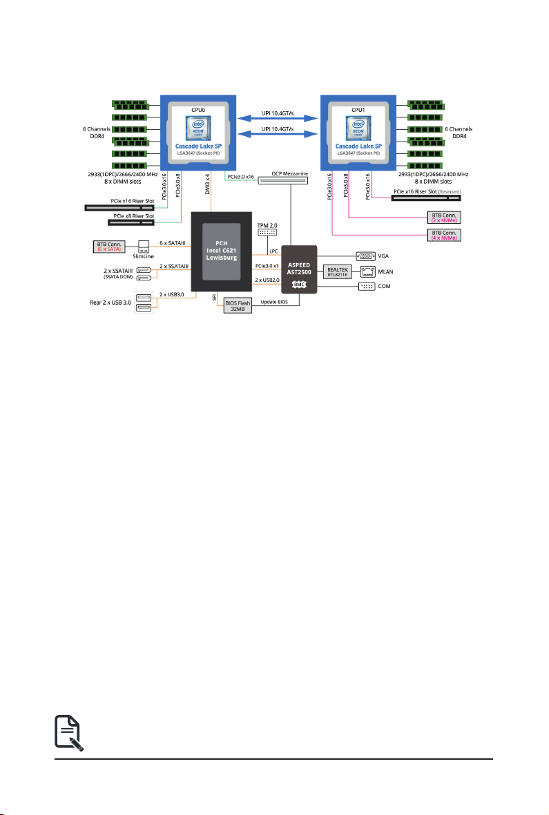
1-3 System Block Diagram
• Please Go to Chapter 4 Motherboard Components for Riser Slot information.
- 18 - Hardware Installation
Page 19
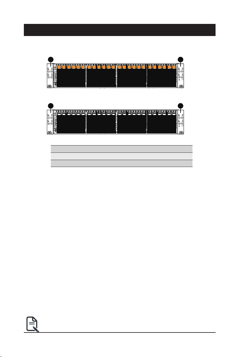
Chapter 2 System Appearance
2-1 Front View
H261-NO0
H261-PC0
1 1
NODE1
RST
NODE2
RST
HDD #0
HDD #1
HDD #2
HDD #3
HDD #4
HDD #5
HDD #6
HDD #7
HDD #8
HDD #9
HDD #10
HDD #11
HDD #12
HDD #13
HDD #14
HDD #18
HDD #15
HDD #19
HDD #16
HDD #17
HDD #20
HDD #21
HDD #22
HDD #23
1 1
NODE1
RST
NODE2
RST
HDD #0
HDD #1
HDD #2
HDD #3
HDD #4
HDD #5
HDD #6
HDD #7
HDD #8
HDD #9
HDD #10
HDD #11
HDD #12
HDD #13
HDD #14
HDD #18
HDD #15
HDD #19
HDD #16
HDD #17
HDD #20
HDD #21
HDD #22
HDD #23
No. Decription
Front Panel LEDs and buttons
1.
Orange HDD Latches Support NVMe
NODE3
RST
NODE4
RST
C
RST
NODE3
RST
NODE4
RST
C
RST
• Please Go to Chapter 2-3 Front Panel LED and Buttons for detail description of
function LEDs.
- 19 - System Appearance
Page 20
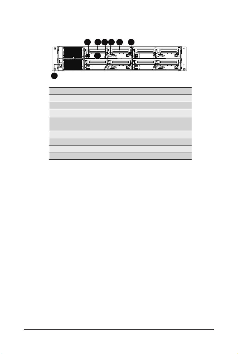
2-2 Rear View
1
No. Decription
1. CMC LAN Port
2. USB 3.0 Port x 2
3. PCIe Card Slot #1
4. Mezzanine Card Slot
5. ID LED
6. VGA Port
7. PCIe Card Slot #2
8. 10/100/1000 Server management LAN port
2 3465 7 8
PSU2
PSU1
(Optional/Supports OCP V2.0 Card)
System Appearance - 20 -
Page 21
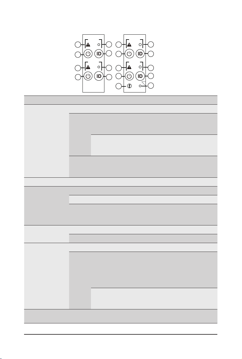
2-3 Front Panel LED and Buttons
NODE1
RST
RST
2
4
2
4
1 1
3
NODE2
1
3
No. Name Color Status Description
Green On System is operating normally.
On
System
1.
Status LED
Reset Button -- -- Press this button to reset the system.
2.
Power button
3.
with LED
ID Button
4.
with LED
Enclosure
5.
CMC
6.
Reset Button
Amber
Blink
N/A Off
Green On System is powered on
Green Blink System is in ACPI S1 state (sleep mode)
N/A Off
Blue On System identication is active.
N/A Off System identication is disabled.
Green On System is operating normally.
On
Amber
Blink
-- -- Press this button to reset the CMC.
NODE3
RST
2
RST
4
2
4
C
RST
6
3
NODE4
1
3
5
Critical condition, may indicates:
System fan failure
System temperature
Non-critical condition, may indicates:
Redundant power module failure
Temperature and voltage issue
Non-critical condition, may indicates:
Redundant power module failure
Temperature and voltage issue
• System is not powered on or in ACPI S5 state (power
off)
• System is in ACPI S4 state (hibernate mode)
Critical condition, may indicates:
Power module failure
System fan failure
Power supply voltage issue
System temperature
Non-critical condition, may indicates:
Redundant power module failure
Temperature and voltage issue
- 21 - System Appearance
Page 22

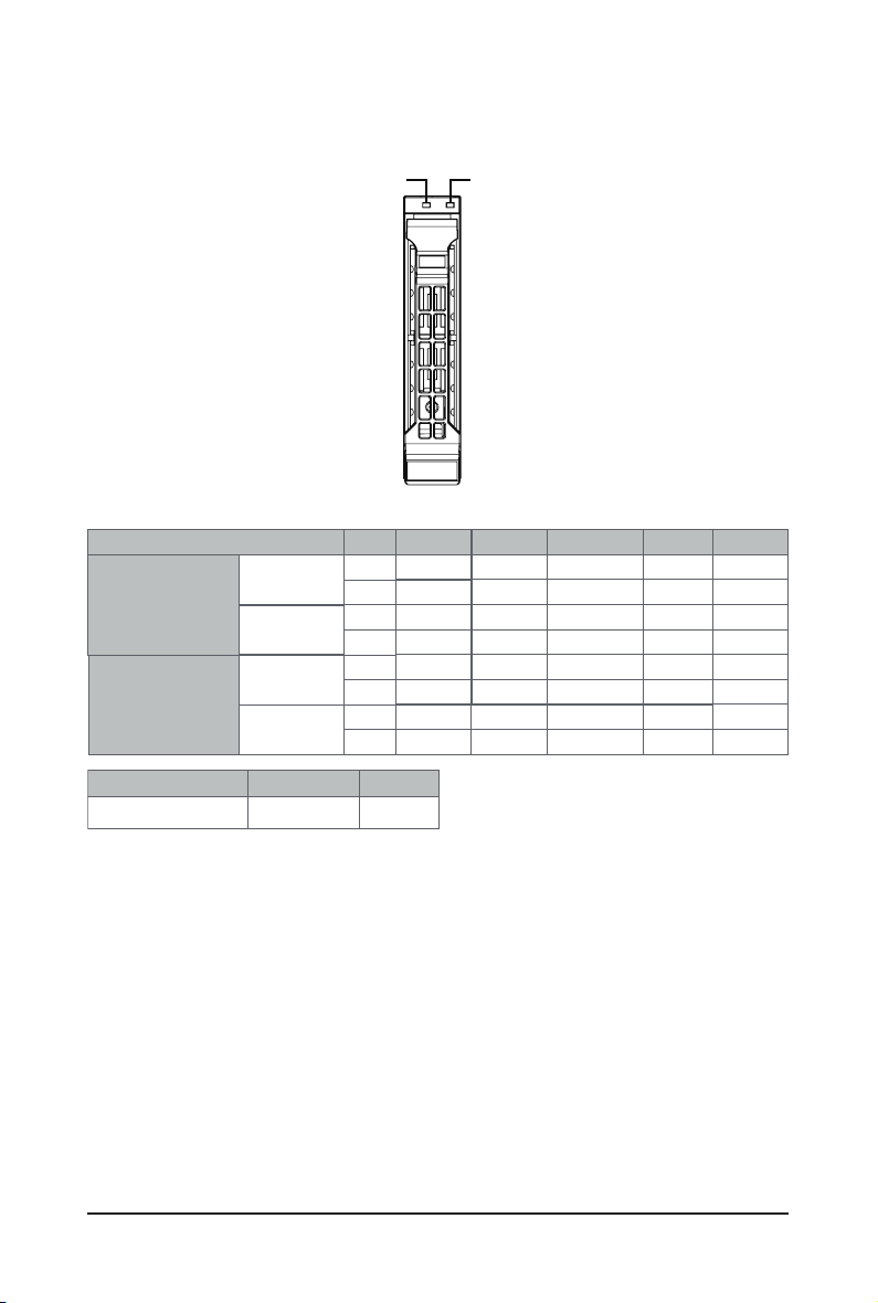
2-4 Rear System LAN LEDs
No. Name Color Status Description
Yel l ow On 1Gbps data rate
Green On 100 Mbps data rate
N/A Off 10 Mbps data rate
On Link between system and
Green
Blink Data transmission or receiving is occurring
N/A Off No data transmission or receiving is occurring
network or no access
1.
2.
1GbE
Speed LED
1GbE
Link/
Activity LED
1 2
System Appearance - 22 -
Page 23
2-5 Hard Disk Drive LEDs
RAID SKU
Disk LED
(LED on
No RAID configuration
(via HBA)
RAID configuration
(via HW RAID Card or
SW RAID Card)
Back Panel)
Removed HDD Slot
(LED on Back Panel)
Disk LED
Removed HDD Slot
/(' /('
OFF
OFF
OFF
OFF
ON
OFF
ON
Rebuilding
(Low Speed: 2 Hz)
(*3)
(*3)
LED1
Locate
ON(*1)
Green
Amber
ON(*1) OFF --
Green
Amber
Green
Amber
ON(*1)
Green
Amber
HDD Fault
OFF
OFF
ON
OFF
OFF
HDD
Access
BLINK (*2)
OFF
--
--
BLINK (*2)
OFF
--
--
HDD Present
(No Access)
OFF
OFF
--
OFF
OFF
--
--
LED 2
Green
HDD Present No HDD
ON
OFF
NOTE:
*1: Depends on HBA/Utility Spec.
*2: Blink cycle depends on HDD's activity signal.
*3: If HDD is pulled out during rebuilding, the disk status of this HDD is regarded as faulty.
- 23 - System Appearance
Page 24
2-6 Power Supply LED Behavior
Power Supply LED
State
OFF No AC power to all power supplies
1Hz Green Blinking AC present / only standby on / Cold redundant mode
2Hz Green Blinking Power supply rmware updateing mode
AC cord unplugged or AC power lost; with a second
Amber
1Hz Amber Blinking
power supply in parallel still with AC input power
Power supply critical event causing shut down:
failure, OCP, OVP, fan failure and UVP
Power supply warning events where the
power supply continues to operate:
high temp, high power, high current and slow fan
Description
System Appearance - 24 -
Page 25

Chapter 3 System Hardware Installation
Pre-installation Instructions
Computer components and electronic circuit boards can be damaged by discharges of static
electricity. Working on computers that are still connected to a power supply can be extremely
dangerous. Follow the simple guidelines below to avoid damage to your computer or injury to
yourself.
• Always disconnect the computer from the power outlet whenever you are working inside the
computer case.
• If possible, wear a grounded wrist strap when you are working inside the computer case.
Alternatively, discharge any static electricity by touching the bare metal system of the computer
case, or the bare metal body of any other grounded appliance.
• Hold electronic circuit boards by the edges only. Do not touch the components on the board
unless it is necessary to do so. Do not ex or stress the circuit board.
• Leave all components inside the static-proof packaging until you are ready to use the component
for the installation.
- 25 - System Hardware Installation
Page 26
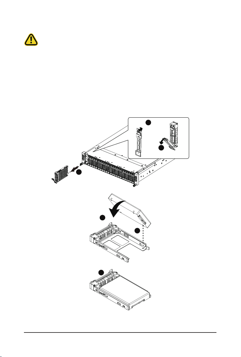
3-1 Installing the Hard Disk Drive
Read the following guidelines before you begin to install the Hard disk drive:
• Take note of the drive tray orientation before sliding it out.
• The tray will not t back into the bay if inserted incorrectly.
• Make sure that the HDD is connected to the HDD connector on the backplane.
Follow these instructions to install the Hard disk drive:
1. Press down the colored release button.
2. Pull out the black locking lever.
3. Use the black locking lever to slide out the HDD tray.
4. Place one side of the HDD at a 45 degree angle into the tray, and align the guiding stand-offs in the
tray with the installation holes of the HDD.
5. Once aligned, push down the other side of the HDD and press it until it clicks.
1
Press
2
Pull
2
5
6
System Hardware Installation - 26 -
4
Page 27
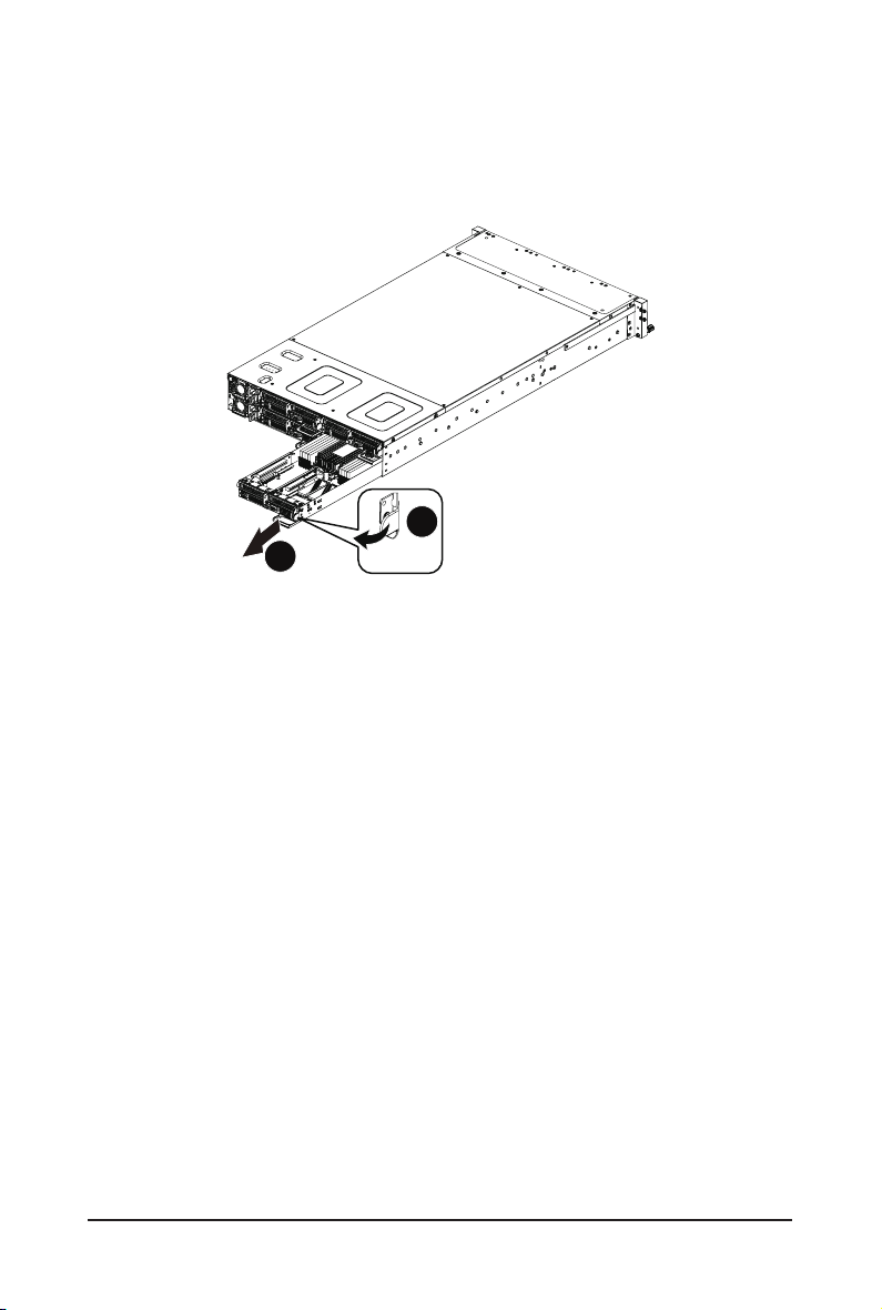
3-2 Removing the Node
Follow these instructions to remove a node:
1. Press the release retaining clip on the right side of the node along the direction of the arrow,
2. Pulling out the node using its handle.
1
2
Press
Pull
- 27 - System Hardware Installation
Page 28
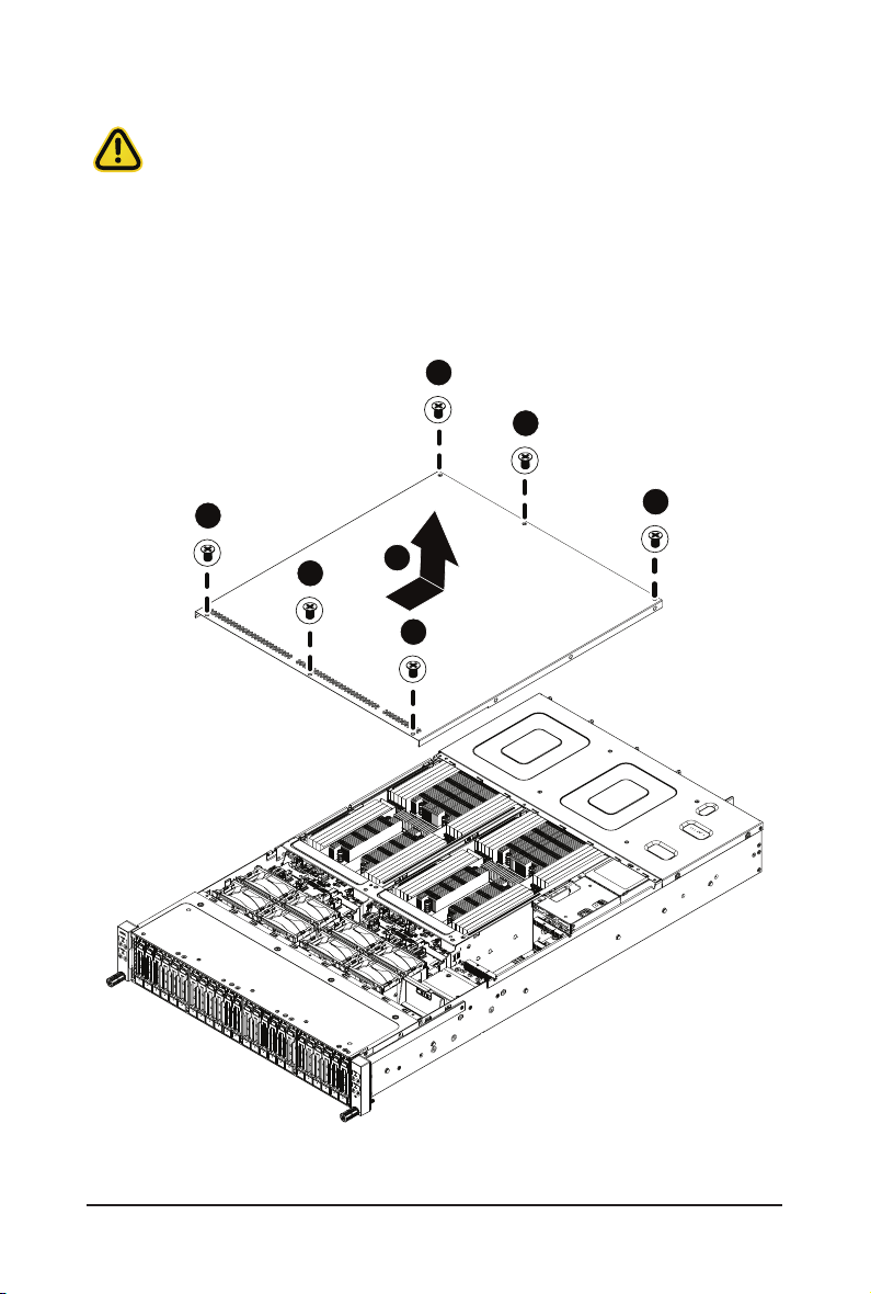
3-3 Removing Chassis Cover
Before you remove or install the system cover
• Make sure the system is not turned on or connected to AC power.
Follow these instructions to remove the system cover:
1. Loosen and remove the six screws securing the back cover.
2. Slide the cover to the rear of the system and remove the cover in the direction of the arrow.
1
1
1
1
2
1
1
System Hardware Installation - 28 -
Page 29

3-4 Removing and Installing the Fan Duct
Follow these instructions to remove/install the fan duct:
1. Remove the two screws securing the fan ducts.
2. Lift up to remove the fan ducts
3. To install the fan duct, align the fan duct with the guiding groove. Push down the fan duct into
chassis until its rmly seats, then install the four screws to secure the fan ducts in place.
1
1
- 29 - System Hardware Installation
Page 30
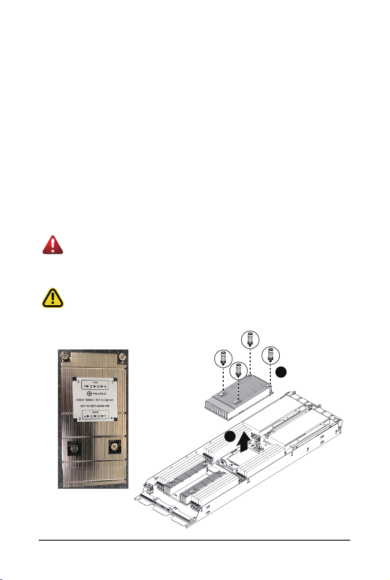
3-5 Removing and Installing the Heatsink
Read the following guidelines before you begin to install the heatsink:
• Always turn off the computer and unplug the power cord from the power outlet before
installing the heatsink to prevent hardware damage.
• Unplug all cables from the power outlets.
• Disconnect all telecommunication cables from their ports.
• Place the system unit on a at and stable surface.
• Open the system according to the instructions.
WARNING!
Failure to properly turn off the server before you start installing components may cause seri-
ous damage. Do not attempt the procedures described in the following sections unless you
are a qualied service technician.
Follow these instructions to remove the heatsink:
1. Loosen the four captive screws securing the heatsink to the system.
2. Lift and remove the heatsink.
WARNING!
CPU0 and CPU1 use different CPU heatsinks. See the following images for
using the correct heatsink.
Failure to observe the warning could result in damage to the equipment.
• When installing the heatsink to CPU, use PHILLIPS #2-Lobe driver to tighten 4 captive
nuts in sequence as 1-4.
• The screw tightening torque: 0 ± 0.5 kgf-cm (22.0± 1.0 lbf-in).
CPU0 Heatsink
System Hardware Installation - 30 -
1
2
Page 31

CPU1 Heatsink:
4
4
1
2
To install the heatsink, reverse the steps above while ensuring that you tighten the captive screws in
sequential order (1g2g3g4) as seen in the image below.
CPU0 Heatsink CPU1 Heatsink:
2
3
1
2
3
- 31 - System Hardware Installation
1
Page 32

3-6 Installing the CPU
Read the following guidelines before you begin to install the CPU:
• Make sure that the motherboard supports the CPU.
• Always turn off the computer and unplug the power cord from the power outlet before
installing the CPU to prevent hardware damage.
• Unplug all cables from the power outlets.
• Disconnect all telecommunication cables from their ports.
• Place the system unit on a at and stable surface.
• Open the system according to the instructions.
WARNING!
Failure to properly turn off the server before you start installing components may cause seri-
ous damage. Do not attempt the procedures described in the following sections unless you
are a qualied service technician.
• When installing the heatsink to CPU, use PHILLIPS #2-Lobe driver to tighten 4 captive nuts
in sequence as 1-4. The screw tightening torque: 14 ± 0.5 kgf-cm (30.0± 1.0 lbf-in).
Follow these instructions to install the CPU:
1. Aligntheprocessortothecarriersothatthegoldtriangleontheprocessoraligns
withthetriangleonthecarrier,andtheninstalltheprocessorintothecarrier.
NOTE: ApplythermalcompoundevenlyonthetopoftheCPU.
2. Carefully flip the heatsink over.Align the carrier assembly so that the triangle
onthe carrieralignswiththe triangle ontheheatsink,and then installthecarrier
assemblyontothebottomoftheheatsink.
3. RemovetheCPUsocketcover.
NOTE: SaveandreplacetheCPUsocketcoveriftheprocessorisremovedfrom
itssocket.
4. AligntheheatsinktotheCPUsocketusingtheguidepinsandmakesurethegold
triangleisinthe correct orientation. Then place the heatsink onto thetopofthe
CPUsocket.
5. Securetheheatsinkbytighteningthescrewsinsequentialorder(1g2g3g4).
NOTE: Whenremovingtheheatsink,loosenthescrewsinreverseorder
(4g3g2g1).
System Hardware Installation - 32 -
Page 33

1
2
3
4
3
2
System Hardware Installation - 33 -
1
4
Page 34

3-7 Installing Memory
Read the following guidelines before you begin to install the memory:
• Make sure that the motherboard supports the memory. It is recommended that memory of
the same capacity, brand, speed, and chips be used.
• Always turn off the computer and unplug the power cord from the power outlet before
installing the memory to prevent hardware damage.
• Memory modules have a foolproof design. A memory module can be installed in only one
direction. If you are unable to insert the memory, switch the direction.
3-7-1 Six Channel Memory Conguration
This motherboard provides 16 DDR4 memory sockets and supports Six Channel Technology. After the
memory is installed, the BIOS will automatically detect the specifications and capacity of the memory.
Enabling eight Channel memory mode will be eight times of the original memory bandwidth.
DIMM_P0_C0
DIMM_P0_B0
DIMM_P0_A0
DIMM_P0_A1
21
&38
DIMM_P0_D1
DIMM_P0_D0
DIMM_P0_E0
DIMM_P0_F0
DIMM_P1_I0
DIMM_P1_H0
DIMM_P1_G0
DIMM_P1_G1
CPU1
DIMM_P1_J1
DIMM_P1_J0
DIMM_P1_K0
DIMM_P1_L0
- 34 - System Hardware Installation
Page 35

3-7-2 Installing the Memory
Before installing a memory module, make sure to turn off the computer and unplug the power
cord from the power outlet to prevent damage to the memory module.
Be sure to install DDR4 DIMMs on this motherboard.
Follow these instructions to install the Memory:
1. Insert the DIMM memory module vertically into the DIMM slot, and push it down.
2. Close the plastic clip at both edges of the DIMM slots to lock the DIMM module.
3. Reverse the installation steps when you want to remove the DIMM module.
2
1
2
3-7-3 DIMM Population Table
Ranks Per DIMM
Type
and Data Width
RDIMM SRx8 4GB 8GB 16GB
RDIMM SRx4 8GB 16GB 32GB
RDIMM DRx8 8GB 16GB 32GB
RDIMM DRx4 16GB 32GB 64GB
RDIMM3DS
LRDIMM QRx4 32GB 64GB 128GB
LRDIMM
3DS
QRx4 N/A 2H-64GB 2H-128GB
8Rx4 N/A 4H-128GB 4H-256GB
QRx4 N/A 2H-64GB 2H-128GB
8Rx4 N/A 4H-128GB 4H-256GB
DIMM Capacity (GB)
DRAM Density 1DPC
4Gb* 8Gb 16Gb 1.2V
System Hardware Installation - 35 -
Speed (MT/s); Voltage (V);
Slots per Channel(SPC) and
DIMM per Channel (DPC)
1 Slot Per Channel
2933
Page 36

3-8 Installing the PCI Expansion Card
• The PCI riser assembly does not include a riser card or any cabling as standard. To install
a PCI card, a riser card must be installed.
Follow these instructions to install the left PCI Expansion card:
1. Remove the three screws securing the riser bracket to the system.
2. Lift up the riser bracket out of system.
3. Align the PCI-E card to the riser guide slot and push in the direction of the arrow until the PCI-E
card sits in the PCI card connector.
4. Secure the PCI-E card with a screw.
5. Reverse steps 1 - 3 to install the riser bracket back into the system.
1
1
1
2
3
4
System Hardware Installation - 36 -
Page 37

Follow these instructions to install the right PCI Expansion card:
1. Remove the two screws on the riser bracket to the system.
2. Lift up the riser bracket out of system.
3. Remove the screw securing the side bracket to the riser bracket.
4. Remove the side bracket
5. Align the PCI-E card to the riser guide slot and push in the direction of the arrow until the PCI-E
card sits in the PCI card connector.
6. Secure the PCI-E card with a screw.
7. Install the side bracket to the riser bracket.
8. Secure the side bracket to the riser bracket with a screw.
9. Reverse steps 1 - 2 to install the riser bracket back into the system.
3
4
2
2
1
5
8
7
6
- 37 - System Hardware Installation
Page 38

3-9 Installing the OCP Card
• Before installing the OCP card the left PCI-E riser assembly must be rst removed, see
the 「Installing the PCI Expansion Card「 section for instructions on removing the PCI-E
riser assembly.
• Use the following type of OCP 2.0 NIC: Type1, P1, P2, P3, P4
Follow these instructions to install the OCP card:
1. Install the OCP card bracket.
2. Secure the OCP card bracket with a screw.
3. Align the OCP card to the connector on the system board and push in the direction of the arrow
until the OCP card sits rmly in the system.
4. Secure the OCP card with three screws.
4
3
1
2
System Hardware Installation - 38 -
Page 39

3-10 Replacing the Fan Assembly
Follow these instructions to replace the fan assembly:
1. Pull the fan ear outward.
2. Lift up the fan assembly from the chassis.
3. Reverse the previous steps to install the replacement fan assembly.
- 39 - System Hardware Installation
Page 40

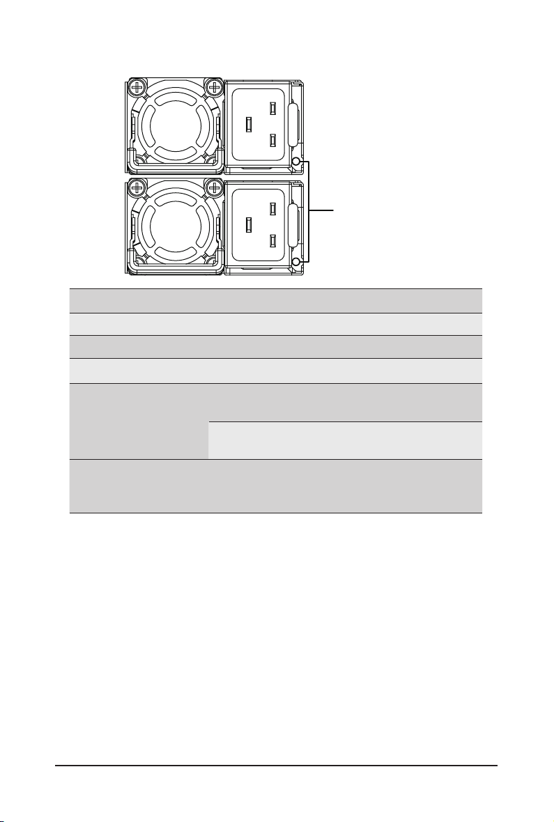
3-11 Replacing the Power Supply
Follow these instructions to replace the power supply:
1. Pull up the power supply handle and press the retaining clip on the right side of the power supply
along the direction of the arrow. At the same time, pull out the power supply by using its handle.
2. Insert the replacement power supply rmly into the chassis. Connect the AC power cord to the
replacement power supply.
PSU2
PSU1
1
3
2
System Hardware Installation - 40 -
Page 41

3-11-1 Power Supply LED Behavior
Power Supply LED
State
OFF No AC power to all power supplies
1Hz Green Blinking AC present / only standby on / Cold redundant mode
2Hz Green Blinking Power supply rmware updateing mode
AC cord unplugged or AC power lost; with a second
Amber
1Hz Amber Blinking
power supply in parallel still with AC input power
Power supply critical event causing shut down:
failure, OCP, OVP, fan failure and UVP
Power supply warning events where the
power supply continues to operate:
high temp, high power, high current and slow fan
Description
- 41 - System Hardware Installation
Page 42

3-12 Replacing Power Distribution Board Cage
1
Before you remove or install the power distribution board cage:
• Make sure the system is not turned on or connected to AC power.
Follow these instructions to remove the power distribution board cage:
1. Loosen and remove the four screws securing the cage.
2. While holding the cage, vertically lift it from the system.
2
System Hardware Installation - 42 -
Page 43

3-13 Cable Routing
3-13-1 H261-NO0
Front Switch Cable/Front LED Cable
PMBus Cable
Power Distribution Board to Middle Board-
Cable (Top)
Power Distribution Board to Middle Board-
Cable (Bottom)
- 43 - System Hardware Installation
Page 44

Top Middle Board to HDD Back Plane Board
Cable (SATA1)
Bottom Middle Board to HDD Back Plane
Board Cable (SATA2)
Top Middle Board to HDD Back Plane Board
Cable (SATA3)
System Hardware Installation - 44 -
Bottom Middle Board to HDD Back Plane
Board Cable (SATA4)
Page 45

Top Middle Board to HDD Back Plane Board
Cable (NVMe/Node1)
Top Middle Board to HDD Back Plane Board
Cable (NVMe/Node1)
Top Middle Board to HDD Back Plane Board
Cable (NVMe/Node3)
Top Middle Board to HDD Back Plane Board
Cable (NVMe/Node3)
- 45 - System Hardware Installation
Page 46

Bottom Middle Board to HDD Back Plane
Board Cable (NVMe/Node2)
Bottom Middle Board to HDD Back Plane
Board Cable (NVMe/Node2)
Bottom Middle Board to HDD Back Plane
Board Cable (NVMe/Node4)
System Hardware Installation - 46 -
Bottom Middle Board to HDD Back Plane
Board Cable (NVMe/Node4)
Page 47

LAN Bridge Cable On-Board SATA to HDD Back Plane Board
Cable
- 47 - System Hardware Installation
Page 48

3-13-2 H261-PC0
Front Switch Cable/Front LED Cable
PMBus Cable
Power Distribution Board to Middle Board-
Cable (Top)
System Hardware Installation - 48 -
Power Distribution Board to Middle Board-
Cable (Bottom)
Page 49

Top Middle Board to HDD Back Plane Cable
(SATA1)
Bottom Middle Board to HDD Back Plane
Cable (SATA2)
Top Middle Board to HDD Back Plane Cable
(SATA3)
Bottom Middle Board to HDD Back Plane
Cable (SATA4)
- 49 - System Hardware Installation
Page 50

LAN Bridge Cable On-Board SATA to HDD Back Plane Board
Cable
System Hardware Installation - 50 -
Page 51

Chapter 4 Motherboard Components
4-1 Motherboard Components
1
2
3
4
5
Item Description
1 USB 3.0 Ports
2 PCI Express x8 Slot
3 Serial Port Connector
4 VGA Port
5 Server Management LAN Port
6 SlimLine SAS Connector
7 NSCI Switch
8 SATA 6Gb/s Connector (suppport SATA DOM)
9 SATA DOM Power Connector
10 Intel Software RIAD Upgrade Key Connector (VROC)
11 Mezzanine Slot #1 (x16 bandwidth)
12 Buzzer
13 SlimLine SAS Connector
14 SATA SGPIO Connector #1
15 SATA SGPIO Connector #2
16 NVMe SSD Connector
17 Battery Socket
18 NVMe SSD Connector
19 NVMe SSD Connector
20 PCI Express x8 Slot #2
21 IPMB Connector
22 TPM Connector
23 SGPIO Connector
24 OCP 2.0 Connector
25 PCI Express x1 Slot #1
24
25
24
20
22
23
21
6
21
9
7
8
10
DIMM_P0_C0
DIMM_P0_B0
DIMM_P0_A0
DIMM_P0_A1
&38
DIMM_P0_D1
DIMM_P0_D0
DIMM_P0_E0
DIMM_P0_F0
11
DIMM_P1_I0
DIMM_P1_H0
DIMM_P1_G0
DIMM_P1_G1
CPU1
DIMM_P1_J1
DIMM_P1_J0
DIMM_P1_K0
DIMM_P1_L0
19
18
17
15
13
13
16
12
Hardware Installation - 51 -
Page 52

4-2 Jumper Setting
Clear
CMOS
CLR_CMOS
BIOS
Recovery
BIOS_RCVR
PMBus
Address Selecon
BIOS_PWD
Intel ME
1
1
Enable
2
Default
3
1
Default
2
Enable
3
Recovery
ME_RCVR
ME
Force
Update
ME_UPDATE
Default
Password
1
2
Enable
3
1
Default
2
Enable
3
Clear
BIOS_PWD
Default
2
Enable
3
1
PCH
2
BMC
3
- 52 - Hardware Installation
Page 53

Chapter 5 BIOS Setup
BIOS (Basic Input and Output System) records hardware parameters of the system in the EFI on the
motherboard. Its major functions include conducting the Power-On Self-Test (POST) during system startup,
saving system parameters, loading the operating system etc. The BIOS includes a BIOS Setup program that
allows the user to modify basic system conguration settings or to activate certain system features. When the
power is turned off, the battery on the motherboard supplies the necessary power to the CMOS to keep the
conguration values in the CMOS.
To access the BIOS Setup program, press the <DEL> key during the POST when the power is turned on.
• BIOS ashing is potentially risky, if you do not encounter any problems when using the current
BIOS version, it is recommended that you don't ash the BIOS. To ash the BIOS, do it with
caution. Inadequate BIOS ashing may result in system malfunction.
• It is recommended that you not alter the default settings (unless you need to) to prevent system
instability or other unexpected results. Inadequately altering the settings may result in system's
failure to boot. If this occurs, try to clear the CMOS values and reset the board to default values.
(Refer to the Exit section in this chapter or introductions of the battery/clearing CMOS jumper in
Chapter 4 for how to clear the CMOS values.)
BIOS Setup Program Function Keys
<f><g> Move the selection bar to select the screen
<h><i> Move the selection bar to select an item
<+> Increase the numeric value or make changes
<-> Decrease the numeric value or make changes
<Enter> Execute command or enter the submenu
<Esc> Main Menu: Exit the BIOS Setup program
Submenus: Exit current submenu
<F1> Show descriptions of general help
<F3> Restore the previous BIOS settings for the current submenus
<F9> Load the Optimized BIOS default settings for the current submenus
<F10> Save all the changes and exit the BIOS Setup program
- 53 - BIOS Setup
Page 54

Main
This setup page includes all the items of the standard compatible BIOS.
Advanced
This setup page includes all the items of AMI BIOS special enhanced features.
(ex: Auto detect fan and temperature status, automatically congure hard disk parameters.)
Chipset
This setup page includes all the submenu options for conguring the functions of the Platform Controller
Hub.
Server Management
Server additional features enabled/disabled setup menus.
Security
Change, set, or disable supervisor and user password. Conguration supervisor password allows you to
restrict access to the system and BIOS Setup.
A supervisor password allows you to make changes in BIOS Setup.
A user password only allows you to view the BIOS settings but not to make changes.
Boot
This setup page provides items for conguration of the boot sequence.
Save & Exit
Save all the changes made in the BIOS Setup program to the CMOS and exit BIOS Setup. (Pressing
<F10> can also carry out this task.)
Abandon all changes and the previous settings remain in effect. Pressing <Y> to the confirmation
message will exit BIOS Setup. (Pressing <Esc> can also carry out this task.)
BIOS Setup - 54 -
Page 55

5-1 The Main Menu
Once you enter the BIOS Setup program, the Main Menu (as shown below) appears on the screen. Use
arrow keys to move among the items and press <Enter> to accept or enter other sub-menu.
Main Menu Help
The on-screen description of a highlighted setup option is displayed on the bottom line of the Main Menu.
Submenu Help
While in a submenu, press <F1> to display a help screen (General Help) of function keys available for the
menu. Press <Esc> to exit the help screen. Help for each item is in the Item Help block on the right side of
the submenu.
• When the system is not stable as usual, select the Restore Defaults item to set your system to
its defaults.
• The BIOS Setup menus described in this chapter are for reference only and may differ by BIOS
version.
- 55 - BIOS Setup
Page 56

Parameter
Description
BIOS Information
Project Name
Project Version
Build Date and Time
BMC Information
(Note)
BMC Firmware Version
(Note)
Displays the project name information.
Displays version number of the BIOS setup utility.
Displays the date and time when the BIOS setup utility was created.
Displays BMC rmware version information.
Processor Information
CPU0 Brand String/ CPU1 Brand
String/ Max CPU Speed / CPU
Signature / Processor Core /
Displays the technical specications for the installed processor(s).
Microcode Patch
Platform Information
Processor/ PCH/ RC Revision
Displays the platform information of the installed processor(s) and
PCH.
(Note) Functions available on selected models.
BIOS Setup - 56 -
Page 57

Parameter
Memory Information
Total Memory
(Note)
Memory Frequency
System Date
System Time
(Note)
Description
Displays the total memory size of the installed memory.
Displays the frequency information of the installed memory.
Sets the date following the weekday-month-day-year format.
Sets the system time following the hour-minute-second format.
(Note)
This section will display capacity and frequency information of the memory that the customer has
installed.
- 57 - BIOS Setup
Page 58

5-2 Advanced Menu
The Advanced Menu displays submenu options for conguring the function of various hardware components.
Select a submenu item, then press <Enter> to access the related submenu screen.
BIOS Setup - 58 -
Page 59

5-2-1 Trusted Computing
Parameter
Conguration
Security Device Support
Disable Block Sid
Description
Enable/Disable the TPM support feature.
Options available: Enable/Disable. Default setting is Enable.
Override to allow SID authentication in TCG storage device.
Options available: Enabled/Disabled. Default setting is Disable.
- 59 - BIOS Setup
Page 60

5-2-2 Serial Port Console Redirection
Parameter
COM1 Console
Redirection
(Note))
Description
Console redirection enables the users to manage the system from a
remote location.
Options available: Enabled/Disabled. Default setting is Disabled.
Press [Enter] to congure advanced items.
Please note that this item is congurable when COM1 Console
Redirection is set to Enabled.
Terminal Type
– Selects a terminal type to be used for console redirection.
– Options available: VT100, VT100+, ANSI, VT-UTF8. Default setting
COM1 Console Redirection
Settings
is VT100+.
Bits per second
– Selects the transfer rate for console redirection.
– Options available: 9600, 19200, 38400, 57600, 115200. Default
setting is 115200.
Data Bits
– Selects the number of data bits used for console redirection.
– Options available: 7/8. Default setting is 8.
(Note) Advanced items prompt when this item is dened.
BIOS Setup - 60 -
Page 61

Parameter
COM1 Console Redirection
Settings (continued)
Description
Parity
– A parity bit can be sent with the data bits to detect some
transmission errors.
– Even: parity bit is 0 if the num of 1's in the data bits is even.
– Odd: parity bit is 0 if num of 1's in the data bits is odd.
– Mark: parity bit is always 1. Space: Parity bit is always 0.
– Mark and Space Parity do not allow for error detection.
– Options available: None, Even, Odd, Mark, Space. Default setting
is None.
Stop Bits
– Stop bits indicate the end of a serial data packet. (A start bit
indicates the beginning). The standard setting is 1 stop bit.
Communication with slow devices may require more than 1 stop
bit.
– Options available: 1/2. Default setting is 1.
Flow Control
– Flow control can prevent data loss from buffer overow. When
sending data, if the receiving buffers are full, a 'stop' signal can
be sent to stop the data ow. Once the buffers are empty, a 'start'
signal can be sent to re-start the ow. Hardware ow control uses
two wires to send start/stop signals.
– Options available: None, Hardware RTS/CTS. Default setting is
None.
VT-UTF8 Combo Key Support
– Enable/Disable the VT-UTF8 Combo Key Support.
– Options available: Enabled/Disabled. Default setting is Enabled.
Recorder Mode
(Note)
– When this mode enabled, only texts will be send. This is to capture
Terminal data.
– Options available: Enabled/Disabled. Default setting is Disabled.
Resolution 100x31
(Note)
– Enable/Disable extended terminal resolution.
– Options available: Enabled/Disabled. Default setting is Enabled.
Putty KeyPad
(Note)
– Selects FunctionKey and LeyPad on Putty.
– Options available: VT100, LINUX, XTERMR6, SC0, ESCN, VT400.
Default setting is VT100.
(Note) Advanced items prompt when this item is dened.
- 61 - BIOS Setup
Page 62

Parameter
Legacy Console Redirection
Legacy Console Redirection
Settings
Serial Port for Out-of-Band
Management / Windows
Emergency Management
Services (EMS) Console
Redirection
(Note)
Serial Port for Out-of-Band
EMS Console Redirection
Settings
Description
Press [Enter] to congure advanced items.
Redirection COM Port
– Selects a COM port for Legacy serial redirection.
– Default setting is COM1.
Resolution
– Selects the number of rows and columns used in Console
Redirection for legacy OS support.
– Options available: 80x24, 80x25. Default setting is 80x24.
Redirect After POST
– When Bootloader is selected, then Legacy Console Redirection
is disabled before booting to legacy OS. When Always Enable is
selected, then Legacy Console Redirection is enabled for legacy
OS.
– Options available: Always Enable, BootLoader. Default setting is
Always Enable.
EMS console redirection allows the user to congure Console Redirection
Settings to support Out-of-Band Serial Port management.
Options available: Enabled/Disabled. Default setting is Disabled.
Press [Enter] to congure advanced items.
Please note that this item is congurable when Serial Port for Out-of-
Band Management EMS Console Redirection is set to Enabled.
Out-of-Band Mgmt Port
– Microsoft Windows Emerency Management Service (EMS) allows
for remote management of a Windows Server OS through a serial
port.
– Default setting is COM1.
Terminal Type
– Selects a terminal type to be used for console redirection.
– Options available: VT100, VT100+, ANSI, VT-UTF8. Default setting
is VT100+.
Bits per second
– Selects the transfer rate for console redirection.
– Options available: 9600, 19200, 38400, 57600, 115200. Default
setting is 115200.
(Note) Advanced items prompt when this item is dened.
BIOS Setup - 62 -
Page 63

Parameter
Serial Port for Out-of-Band
EMS Console Redirection
Settings(continued)
Description
Flow Control
– Flow control can prevent data loss from buffer overow. When
sending data, if the receiving buffers are full, a 'stop' signal can
be sent to stop the data ow. Once the buffers are empty, a 'start'
signal can be sent to re-start the ow. Hardware ow control uses
two wires to send start/stop signals.
– Options available: None, Hardware RTS/CTS, Software Xon/Xoff.
Default setting is None.
BIOS Setup - 63 -
Page 64

5-2-3 SIO Conguration
Parameter
AMI SIO Driver Version
Super IO Chip Logical
Device(s) Conguration
[*Active*] Serial Port
BIOS Setup - 64 -
Description
Displays the AMI SIO driver version information.
Press [Enter] to congure advanced items.
Use This Device
– When set to Enabled allows you to congure the serial port settings.
When set to Disabled, displays no conguration for the serial port.
– Options available: Enabled/Disabled. Default setting is Enabled.
Current:
– Displays the serial port base I/O address and IRQ.
Possible:
– Congures the serial port base I/O address and IRQ.
Use Automatic Settings
IO=3F8h; IRQ=4; DMA;
IO=3F8h; IRQ=3, 4, 5, 7, 9, 10, 11, 12; DMA;
IO=2F8h; IRQ=3, 4, 5, 7, 9, 10, 11, 12; DMA;
IO=3E8h; IRQ=3, 4, 5, 7, 9, 10, 11, 12; DMA;
IO=2E8h; IRQ=3, 4, 5, 7, 9, 10, 11, 12; DMA;
Default setting is Use Automatic Settings.
Page 65

5-2-4 PCI Subsystem Settings
Parameter
PCI Bus Driver Version
PCI Express Slot # I/O ROM
(Note1)
Description
Displays the PCI Bus Driver version information.
When enabled, this setting will initialize the device expansion
ROM for the related PCI-E slot.
Options available: Enabled/Disabled. Default setting is Enabled.
When enabled, this setting will initialize the device expansion
ROM for the related NVME devices.
NVME1/2/3/4/5/6 I/O ROM
(Note2)
Options available: Enabled/Disabled. Default setting is Enabled.
PCI Devices Common Settings
Enable/Disable memory mapped I/O to 4GB or greater address
Above 4G Decoding
space (Above 4G Decoding).
Options available: Enabled/Disabled. Default setting is Enabled.
If the system has SR-IOV capable PCIe devices, this item
SR-IOV Support
Enable/Disable Single Root IO Virtualization Support.
Options available: Enabled/Disabled. Default setting is Enabled.
(Note1) This section is dependent on the available PCIe Slot.
(Note2) Functions available on selected models.
BIOS Setup - 65 -
Page 66

5-2-5 USB Conguration
Parameter
Description
USB Conguration
USB Devices:
XHCI Hand-off
USB Mass Storage Driver
(Note)
Support
Displays the USB devices connected to the system.
Enable/Disable the XHCI (USB 3.0) Hand-off support.
Options available: Enabled/Disabled. Default setting is Enabled.
Enable/Disable the USB Mass Storage Driver Support.
Options available: Enabled/Disabled. Default setting is Enabled.
Enables the I/O port 60h/64h emulation support. This should be
Port 60/64 Emulation
enabled for the complete USB Keyboard Legacy support for nonUSB aware OS.
Options available: Enabled/Disabled. Default setting is Enabled.
(Note) This item is present only if you attach USB devices.
BIOS Setup - 66 -
Page 67

5-2-6 Post Report Conguration
Parameter
Post Report Conguration
Error Message Report
Post Error Message
Description
Enable/Disable the POST Error Message support.
Options available: Enabled/Disabled. Default setting is Enabled.
- 67 - BIOS Setup
Page 68

5-2-7 NVMe Conguration
Parameter
NVMe Conguration
NVMe OPROM Select
Description
Displays the NVMe devices connected to the system
Options available: BIOS Build-In, NVMe Device. Default setting is BIOS
Build-In.
- 68 - BIOS Setup
Page 69

5-2-8 Chipset Conguration
Parameter
Description
Denes the power state to resume to after a system shutdown that is
due to an interruption in AC power. When set to Last State, the system
will return to the active power state prior to shutdown. When set to
Restore on AC Power Loss
(Note)
Power Off, the system remains off after power shutdown.
Options available: Last State, Power Off, Power On, Unspecied. The
default setting depends on the BMC setting.
Enable/Disable 64bit capable devices to be decoded in Skip Above 4G
Skip Above 4G Decoding for VGA
Address VGA Space.
Options available: Enabled/Disabled. Default setting is Disabled.
P2P Bridge IO Size
Sets P2P Bridge IO aligned to the size.
Options available: 0x100, 0x150, 0x1000. Default setting is 0x1000.
Enable/Disable the chassis intrusion alert function.
Chassis Opened Warning
Options available: Enabled, Disabled, Clear. Default setting is
Disabled.
(Note) When the power policy is controlled by BMC, please wait for 15-20 seconds for BMC to save the
last power state.
- 69 - BIOS Setup
Page 70

5-2-9 Network Stack Conguration
Parameter
Network Stack
Ipv4 PXE Support
Ipv4 HTTP Support
Ipv6 PXE Support
Ipv6 HTTP Support
IPSEC Certicate
PXE boot wait time
Media detect count
(Note)
(Note)
(Note)
(Note)
(Note)
(Note)
(Note)
Description
Enable/Disable the UEFI network stack.
Options available: Enabled/Disabled. Default setting is Enabled.
Enable/Disable the Ipv4 PXE feature.
Options available: Enabled/Disabled. Default setting is Enabled.
Enable/Disable the Ipv4 HTTP feature.
Options available: Enabled/Disabled. Default setting is Disabled.
Enable/Disable the Ipv6 PXE feature.
Options available: Enabled/Disabled. Default setting is Disabled.
Enable/Disable the Ipv6 HTTP feature.
Options available: Enabled/Disabled. Default setting is Disabled.
Enable/Disable the IPSEC Certicate feature.
Options available: Enabled/Disabled. Default setting is Enabled.
Press the <+> / <-> keys to increase or decrease the desired values.
Press the <+> / <-> keys to increase or decrease the desired values.
(Note) This item appears when Network Stack is set to Enabled.
- 70 - BIOS Setup
Page 71

5-2-10 iSCSI Conguration
Parameter
iSCSI Initiator Name
Add an Attempt
Delete Attempts
Change Attempt Order
BIOS Setup - 71 -
Description
Press [Enter] to congure advanced items.
Press [Enter] to congure advanced items.
Press [Enter] to congure advanced items.
Page 72

5-2-11 Driver Health
Parameter
Driver Health
BIOS Setup - 72 -
Description
Displays driver health status of the devices/controllers if installed
Page 73

5-3 Chipset Setup Menu
Chipset Setup menu displays submenu options for conguring the function of Platform Controller Hub(PCH).
Select a submenu item, then press <Enter> to access the related submenu screen.
- 73 - BIOS Setup
Page 74

5-3-1 Processor Conguration
BIOS Setup - 74 -
Page 75

Parameter
Processor Conguration
Per-Socket Conguration
Processor Socket / Processor ID /
Processor Frequency / Processor
Max Ratio / Processor Min Ratio
/ Microcode Revision / L1 Cache
RAM / L2 Cache RAM / L3 Cache
RAM / Processor 0 Version /
Processor 1 Version
Hyper-Threading [All]
Enable Intel(R) TXT
VMX (Vanderpool Technology)
Enable SMX
Hardware Prefetcher
L2 RF0 Prefetch Disable
Adjacent Cache Prefetch
DCU Streamer Prefetcher
DCU IP Prefetcher
AES-NI
Description
Press [Enter] to congure advanced items.
CPU Socket 0/1 Conguration
– Press [Enter] to congure advanced items.
Core Disable Bitmap(Hex) (for CPU socket 0/1)
– Number of Cores to enable. 0 means all cores. FFFFFFF
means to disable all cores. The maximum value depends on the
number of CPUs available. Press the numeric keys to adjust
desired values.
Displays the technical specications for the installed processor(s).
The Hyper Threading Technology allows a single processor to execute
two or more separate threads concurrently. When hyper-threading is
enabled, multi-threaded software applications can execute their threads,
thereby improving performance.
Options available: Enable/Disable. Default setting is Enable.
Enable/Disable the Intel Trusted Execution Technology support function.
Options available: Enable/Disable. Default setting is Disable.
Enable/Disable the Vanderpool Technology. This will take effect after
rebooting the system.
Options available: Enable/Disable. Default setting is Enable.
Enable/Disable the Secure Mode Extensions (SMX) support function.
Options available: Enable/Disable. Default setting is Disable.
Select whether to enable the speculative prefetch unit of the processor.
Options available: Enable/Disable. Default setting is Disable.
Options available: Enable/Disable. Default setting is Disable.
When enabled, cache lines are fetched in pairs. When disabled, only
the required cache line is fetched.
Options available: Enable/Disable. Default setting is Enable.
Prefetches the next L1 data line based upon multiple loads in same
cache line.
Options available: Enable/Disable. Default setting is Enable.
Prefetches the next L1 Data line based upon sequential load history.
Options available: Enable/Disable. Default setting is Enable.
Enable/Disable the AES-NI (Intel Advanced Encryption Standard New
Instructions) support function.
Options available: Enable/Disable. Default setting is Enable.
BIOS Setup - 75 -
Page 76

5-3-2 Common RefCode Conguration
Parameter
Common RefCode Conguration
MMIO High Base
MMIO High Granularity Size
Isoc Mode
Numa (Non-Uniform Memory
Access)
Description
Selects the MMIO High Base setting.
Options available: 56T, 40T, 24T, 16T, 4T, 1T. Default setting is 56T.
Selects the allocation size used to assign mmioh resources.
Total mmioh space can be up to 32xgranularity. Per stack mmioh
resource assignments are multiples of the granularity where 1 unit
per stack is the default allocation.
Options available: 1G, 4G, 16G, 64G, 256G, 1024G. Default setting
is 256G.
Enable/Disable the Isochronous support in order to meet the QoS
requirements (Quality of Service).
Options available: Auto, Enable, Disable. Default setting is Auto.
Enable/Disable Non-uniform Memory Access (NUMA) support to
improve the system performance.
Options available: Enable/Disable. Default setting is Enable.
- 76 - BIOS Setup
Page 77

5-3-3 UPI Conguration
BIOS Setup - 77 -
Page 78

Parameter
UPI Conguration
UPI General Conguration
Description
Press [Enter] to congure advanced items.
UPI Status
– Press [Enter] to view the UPI status.
Link Frequency Select
– Selects the UPI link frequency.
– Options available: 9.6GB/s, 10.4GB/s, Auto. Default setting is Auto.
SNC
– Enable/Disable Sub NUMA Cluster function.
– Options available: Disable, Enable, Auto. Default setting is Disable.
Stale AtoS
– Enable/Disable Stale A to S directory optimization.
– Options available: Disable, Enable, Auto. Default setting is Disable.
LLC dead line alloc
– Enable/Disable ll dead lines in LLC.
– Options available: Disable, Enable, Auto. Default setting is Auto.
- 78 - BIOS Setup
Page 79

5-3-4 Memory Conguration
Parameter
Integrated Memory Controller (iMC)
Enforce POR
Memory Frequency
Enable ADR
Legacy ADR Mode
ADR Data Save Mode
Erase-ARM NVDIMMs
Restore NVDIMMs
Description
When set to Enable, the system enforces Plan Of Record restrictions
for DDR4 frequency and voltage programming. When set to Auto,
the system sets it to the MRC default settings.
Options available: Auto, POR, Disable. Default setting is Auto.
Congures the maximum memory frequency.
Options available: Auto, 2133, 2400, 2666, 2933.
Default setting is Auto.
Enables the detecting and enabling of ADR (Asynchronous DRAM
Refresh) function.
Options available: Enable/Disable. Default setting is Enable.
Enable/Disable the Legacy ADR Mode.
Options available: Enable/Disable. Default setting is Disable.
Species the Data Save Mode for ADR. Batterybacked or Type 01
NVDIMM.
Options available: Disable, Batterybacked DIMMs, NVDIMMs.
Default setting is NVDIMMs.
Enable/Disable Erasing and Arming NVDIMMs.
Options available: Enable/Disable. Default setting is Enable.
Enable/Disable Automatic restoring of NVDIMMs.
Options available: Enable/Disable. Default setting is Enable.
- 79 - BIOS Setup
Page 80

Parameter
Interleave NVDIMMs
Assert ADR on Reset
Assert ADR on S5
Memory Topology
Memory Map
Memory RAS Conguration
Description
Controls if NVDIMMs are interleaved together or not.
Options available: Enable/Disable. Default setting is Disable.
Enable/Disable Assert ADR on Reset.
Options available: Enable/Disable. Default setting is Disable.
Enable/Disable Assert ADR on S5.
Options available: Enable/Disable. Default setting is Disable.
Press [Enter] to view memory topology with DIMM population
information.
Press [Enter] to congure advanced items.
IMC Interleaving
– controls the interleaving between the Integrated Memory
Controllers (IMCs).
– Options available: Auto, 1-way Interleave, 2-way Interleave.
Default setting is Auto.
Press [Enter] to congure advanced items.
RAS Type
– Displays the RAS type.
Static Virtual Lockstep Mode
– Enable/Disable the Static Virtual Lockstep mode.
– Options available: Disable/Enable. Default setting is Disable.
Mirror Mode
– Mirror Mode will set entire 1LM/2LM memory in system to be
mirrored, consequently reducing the memory capacity by half.
Enables the Mirror Mode will disable the XPT Prefetch.
– Options available: Disable/Enable Mirror Mode (1LM). Default
setting is Disable.
Memory Rank Sparing
– Enable/Disable Memory Rank Sparing. This feature is only
available on 1LM.
– Options available: Disable/Enable. Default setting is Disable.
Correctable Error Threshold
– Correctable Error Threshold (1-32767) used for sparing, tagging,
and leaky bucket.
– Press the <+> / <-> keys to increase or decrease the desired
values.
SDDC Plus One
– Enable/Disable SDDC Plus One.
– Options available: Disable/Enable. Default setting is Disable.
- 80 - BIOS Setup
Page 81

5-3-5 IIO Conguration
Parameter
IIO Conguration
Intel
VT for Directed I/O (VT-d)
®
Description
Press [Enter] to congure advanced items.
Intel
VT for Directed I/O (VT-d)
®
– Enable/Disable the Intel VT for Directed I/O (VT-d) support
function by reporting the I/O device assignment to VMM through
DMAR ACPI Tables.
– Options available: Enable/Disable. Default setting is Enable.
ACS Control
– Enable: Programs ACS only to Chipset Pcie Root Ports Bridges.
– Disable: Programs ACS to all PCIe bridges.
– Default setting is Enable.
Interrupt Remapping
– Enable/Disable the interrupt remapping support function.
– Options available: Enable/Disable. Default setting is Enable.
PassThrough DMA
– Enable/Disable the Non-Isoch VT_D Engine PassThrough DMA
support function.
– Options available: Enable/Disable. Default setting is Enable.
ATS
– Enable/Disable Non-Isoch VT_D Engine ATS support.
– Options available: Enable/Disable. Default setting is Enable.
- 81 - BIOS Setup
Page 82

Parameter
Intel
VT for Directed I/O (VT-d)
®
(continued)
Intel
VMD technology
®
MCTP
Description
Post Interrupt
– Enable/Disable VT_D posted interrupt.
– Options available: Enable/Disable. Default setting is Enable.
Coherency Support (Non-Isoch)
– Enable/Disable Non-Isoch VT_D Engine Coherency support.
– Options available: Enable/Disable. Default setting is Enable.
Press [Enter] to congure advanced items.
Intel
VMD technology
®
Intel® VMD Conguration
– Enable/Disable the Intel VMD support function.
– Options available: Enable/Disable. Default setting is Disable.
Intel
VMD for Non-Hotplug NVMe
®
– Enable/Disable the Intel VMD support for Non-Hotplug NVMe.
– Options available: Enable/Disable. Default setting is Enable.
Enable/Disable MCTP (Management Component Transport Protocol).
Options available: Enable/Disable. Default setting is Disable.
(Note)
(Note) This item appears when Intel® VMD Conguration is set to Enabled.
- 82 - BIOS Setup
Page 83

5-3-6 Advanced Power Management Conguration
Parameter
Advanced Power Management
Conguration
CPU P State Control
Description
Press [Enter] to congure advanced items.
SpeedStep (Pstates)
– Conventional Intel SpeedStep Technology switches both voltage
and frequency in tandem between high and low levels in response
to processor load.
– Options available: Enable/Disable. Default setting is Enable.
Turbo Mode
– When this item is enabled, the processor will automatically ramp
up the clock speed of 1-2 of its processing cores to improve its
performance. When this item is disabled, the processor will not
overclock any of its core.
– Options available: Enable/Disable. Default setting is Enable.
- 83 - BIOS Setup
Page 84

Parameter
Description
Press [Enter] to congure advanced items.
Hardware P-States
– When this item is disabled, the processor hardware chooses a
P-state based on OS Request (Legacy P-States).
Hardware PM State Control
– In Native mode, the processor hardware chooses a P-state based
on OS guidance.
– In Out of Band mode, the processor hardware autonomously
chooses a P-state (with no OS guidance).
– Options available: Disable, Native Mode, Out of Band Mode, Native
Mode with No Legacy Support. Default setting is Native Mode.
Press [Enter] to congure advanced items.
Autonomous Core C-State
– Enable/Disable the Autonomous Core C-State Control.
– Options available: Enable/Disable. Default setting is Disable.
CPU C6 Report
– Allows you to determine whether to let the CPU enter C6 mode
CPU C State Control
in system halt state. When enabled, the CPU core frequency and
voltage will be reduced during system halt state to decrease power
consumption. The C6 state is a more enhanced power-saving state
than C1.
– Options available: Disable, Enable, Auto. Default setting is Auto.
Enhanced Halt State (C1E)
– Core C1E auto promotion control. Takes effect after reboot.
– Options available: Enable/Disable. Default setting is Enable.
Congures the state for the C-State package limit.
Package C State Control
Options available: C0/C1 state, C2 state, C6(non Retention) state,
C6(Retention) state, No Limit, Auto.
Default setting is Auto.
Press [Enter] to congure advanced items.
Energy Perf BIAS
– Enters the Energy Perf BIAS submenu.
Power Performance Tuning
– Tunes the Power Performance Conguration mode. When enabled,
uses IA32_ENERGY_PERF_BIAS input from the core. When
disabled, uses alternate performance BIAS input from ENERGY_
CPU - Advanced PM Tuning
PERF_BIAS_CONFIG.
– Options available: OS Controls EPB, BIOS Controls EPB. Default
setting is OS Controls EPB.
Energy_PERF_BIAS_CFG mode
– Selects the Energy Performance Bias Conguration Mode.
– Options available: Performance, Balanced Performance, Balanced
Power, Power. Default setting is Balanced Performance.
– Please note that this item is congurable when Power Performance
Tuning is set to BIOS Controls EPB.
(Note) Advanced items prompt when this item is dened.
- 84 - BIOS Setup
(Note)
(Note)
Page 85

5-3-7 PCH Conguration
Parameter
PCH Conguration
PCH SATA Conguration
Description
Press [Enter] to congure advanced items.
SATA Controller
– Enable/Disable SATA controller.
– Options available: Enable/Disable. Default setting is Enable.
Congure SATA as
– Congures on chip SATA type.
– AHCI Mode: When set to AHCI, the SATA controller enables its AHCI
functionality. Then the RAID function is disabled and cannot be
access the RAID setup utility at boot time.
– RAID Mode: When set to RAID, the SATA controller enables both its
RAID and AHCI functions. You will be allowed to access the RAID
setup utility at boot time.
– Options available: AHCI, RAID. Default setting is AHCI.
Alternate Device ID on RAID
(Note 1)
– Enable/Disable Alternate Device ID on RAID mode.
– Options available: Enable/Disable. Default setting is Disabled
– Please note that this option appears when HDD is in RAID Mode.
SATA Port 0/1/2/3/4/5/6/7
– The category identies SATA hard drives that are installed in the
computer. System will automatically detect HDD type.
- 85 - BIOS Setup
Page 86

Parameter
PCH SATA Conguration
(continued)
PCH sSATA Conguration
Description
Port 0/1/2/3/4/5/6/7
– Enable/Disable Port 0/1/2/3/4/5/6/7 device.
– Options available: Enable/Disable. Default setting is Enable.
Hot Plug (for Port 0/1/2/3/4/5/6/7)
(Note 2)
– Enable/Disable HDD Hot-Plug function.
– Options available: Enable/Disable. Default setting is Disable.
Spin Up Device (for Port 0/1/2/3/4/5/6/7)
(Note 2)
– On an edge detect from 0 to 1, the PCH starts a COM reset
initialization to the device.
– Options available: Enable/Disable. Default setting is Disable.
sSATA Controller
– Enable/Disable sSATA controller.
– Options available: Enable/Disable. Default setting is Enable.
Congure sSATA as
– Congures on chip SATA type.
– AHCI Mode: When set to AHCI, the SATA controller enables its AHCI
functionality. Then the RAID function is disabled and cannot be access
the RAID setup utility at boot time.
– RAID Mode: When set to RAID, the SATA controller enables both its
RAID and AHCI functions. You will be allowed to access the RAID
setup utility at boot time.
– Options available: AHCI, RAID. Default setting is AHCI.
Alternate Device ID on RAID
(Note 1)
– Enable/Disable Alternate Device ID on RAID mode.
– Options available: Enable/Disable. Default setting is Disabled.
– Please note that this option appears when HDD is in RAID Mode.
sSATA Port 0/1/2/3/4/5
– The category identies sSATA hard drives that are installed in the
computer. System will automatically detect HDD type.
Port 0/1/2/3/4/5
– Enable/Disable Port 0/1/2/3/4/5 device.
– Options available: Enable/Disable. Default setting is Enable.
Hot Plug (for Port 0/1/2/3/4/5)
(Note 2)
– Enable/Disable HDD Hot-Plug function.
– Options available: Enable/Disable. Default setting is Disable.
Spin Up Device (for Port 0/1/2/3/4/5)
(Note 2)
– On an edge detect from 0 to 1, the PCH starts a COM reset
initialization to the device.
– Options available: Enable/Disable. Default setting is Disabled.
(Note 1) Only appears when HDD sets to RAID Mode.
(Note 2) Only Supported when HDD is in AHCI or RAID Mode.
- 86 - BIOS Setup
Page 87

5-3-8 Miscellaneous Conguration
Parameter
Miscellaneous Conguration
Active Video
Description
Selects the active video type.
Options available: Auto, Onboard Device, PCIE Device. Default setting is
Auto.
- 87 - BIOS Setup
Page 88

5-3-9 Server ME Conguration
Parameter
General ME Conguration
Oper. Firmware Version
ME Firmware Status #1/#2
Current State (for ME Firmware)
Error Code (for ME Firmware)
Recovery Cause (for ME Firmware)
PTT Support
Suppress PTT Commands
BIOS Setup - 88 -
Description
Displays the operational rmware version.
Displays ME Firmware status information.
Displays ME Firmware current status information.
Displays ME Firmware status error code.
Displays ME Firmware recovery cause.
Displays if the system supports the Intel® Platform Trust
Technology.
Displays if the system supports to Bypass TPM2 commands
submitting to PTT Firmware.
Page 89

5-3-10 Runtime Error Logging Settings
Parameter
Runtime Error Logging
System Errors
S/W Error Injection Support
Whea Settings
Memory Error Enabling
Description
Enable/Disable system error logging function.
Options available: Enable/Disable. Default setting is Enable.
Enable/Disable software injection error logging function.
Options available: Enable/Disable. Default setting is Disable.
Press [Enter] to congure advanced items.
WHEA (Windows Hardware Error Architecture) Support
– Enable/Disable WHEA Support.
– Options available: Enable/Disable. Default setting is Enable.
Press [Enter] to congure advanced items.
Memory Error
– Enable/Disable Memory Error.
– Options available: Enable/Disable. Default setting is Enable.
Memory Corrected Error
– Enable/Disable Memory Corrected Error.
– Options available: Enable/Disable. Default setting is Enable.
Uncorrected Error disable Memory
– Enable/Disable the Memory that triggers Uncorrected Error.
– Options available: Enable/Disable. Default setting is Disable.
- 89 - BIOS Setup
Page 90

Parameter
PCIe Error Enabling
Description
Press [Enter] to congure advanced items.
Corrected Error
– Enables and escalates Correctable Errors to error pins.
– Options available: Enable/Disable. Default setting is Enable.
Uncorrected Error
– Enables and escalates Uncorrectable/Recoverable Errors to error pins.
– Options available: Enable/Disable. Default setting is Enable.
Fatal Error Enable
– Enables and escalates Fatal Errors to error pins.
– Options available: Enable/Disable. Default setting is Enable.
SERR Propagation
– Enable/Disable SERR propagation.
– Options available: Enable/Disable. Default setting is Enable.
PERR Propagation
– Enable/Disable PERR propagation.
– Options available: Enable/Disable. Default setting is Enable.
- 90 - BIOS Setup
Page 91

5-3-11 Power Policy
Parameter
Description
Selects a Power Policy Quick Setting.
Power Policy Quick Settings
Options available: Standard, Best Performance, Energy Efcient, Turbo
Lock. Default setting is Standard.
Conventional Intel SpeedStep Technology switches both voltage and
SpeedStep (Pstates)
frequency in tandem between high and low levels in response to processor
load.
Options available: Enable/Disable. Default setting is Enable.
When this item is enabled, the processor will automatically ramp up the
Turbo Mode
clock speed of 1-2 of its processing cores to improve its performance.
When this item is disabled, the processor will not overclock any of its core.
Options available: Enable/Disable. Default setting is Enable.
Allows you to determine whether to let the CPU enter C6 mode in system
halt state. When enabled, the CPU core frequency and voltage will be
CPU C6 report
reduced during system halt state to decrease power consumption. The C6
state is a more enhanced powersaving state than C1.
Options available: Disable, Enable, Auto. Default setting is Auto.
Core C1E auto promotion control. Takes effect after reboot.
Enhanced Halt State (C1E)
(Note)
Options available: Enable/Disable. Default setting is Enable.
(Note) Advanced items prompt when this item is dened.
- 91 - BIOS Setup
Page 92

Parameter
Package C State
Hyper-Threading [ALL]
Hardware Prefetcher
Adjacent Cache Prefetch
DCU Streamer Prefetcher
Isoc Mode
Intel
VT for Directed I/O (VT-d)
®
Link Frequency Select
Description
Congures the state for the C-State package limit.
Options available: C0/C1 state, C2 state, C6(non Retention) state,
C6(Retention) state, No Limit, Auto. Default setting is Auto.
The Hyper Threading Technology allows a single processor to execute
two or more separate threads concurrently. When hyper-threading is
enabled, multi-threaded software applications can execute their threads,
thereby improving performance.
Options available: Enable/Disable. Default setting is Enable.
Select whether to enable the speculative prefetch unit of the processor.
Options available: Enable/Disable. Default setting is Disable.
When enabled, cache lines are fetched in pairs. When disabled, only the
required cache line is fetched.
Options available: Enable/Disable. Default setting is Enable.
Prefetches the next L1 data line based upon multiple loads in same cache
line.
Options available: Enable/Disable. Default setting is Enable.
Enable/Disable the Isochronous support in order to meet the QoS
requirements (Quality of Service).
Options available: Auto, Enable, Disable. Default setting is Auto.
Enable/Disable the Intel VT for Directed I/O (VT-d) support function by
reporting the I/O device assignment to VMM through DMAR ACPI Tables.
Options available: Enable/Disable. Default setting is Enable.
Selects the UPI link frequency.
Options available: 9.6GB/s, 10.4GB/s, Auto. Default setting is Auto.
- 92 - BIOS Setup
Page 93

5-4 Server Management Menu
Parameter
FRB-2 Timer
FRB-2 Timer
timeout
FRB-2 Timer Policy
OS Watchdog
Timer
OS Wtd Timer
Timeout
BIOS Setup - 93 -
Description
Enable/Disable FRB-2 timer (POST timer).
Options available: Enabled/Disabled. Default setting is Disabled.
Congure the FRB2 Timer timeout.
Options available: 3 minutes, 4 minutes, 5 minutes, 6 minutes. Default setting is 6
minutes.
Please note that this item is congurable when FRB-2 Timer is set to Enabled.
Congure the FRB2 Timer policy.
Options available: Do Nothing, Reset, Power Down, Power Cycle.
Default setting is Do Nothing.
Please note that this item is congurable when FRB-2 Timer is set to Enabled.
Enable/Disable OS Watchdog Timer function.
Options available: Enabled/Disabled. Default setting is Disabled.
Congure OS Watchdog Timer.
Options available: 5 minutes, 10 minutes, 15 minutes, 20 minutes. Default setting is
5 minutes.
Please note that this item is congurable when OS Watchdog Timer is set to
Enabled.
Page 94

Parameter
OS Wtd Timer
Policy
Wait BMC Ready
System Event Log
View FRU
Information
BMC VLAN
Conguration
BMC network
conguration
IPv6 BMC Network
Conguration
Description
Congure OS Watchdog Timer Policy.
Options available: Reset, Do Nothing, Power Down, Power Cycle. Default setting is
Reset.
Please note that this item is congurable when OS Watchdog Timer is set to
Enabled.
POST wait BMC ready and reboot system.
Options available: Disabled, 2 minutes, 4 minutes, 6 minutes.
Default setting is 2 minutes.
Press [Enter] to congure advanced items.
Press [Enter] to view the advanced items.
Press [Enter] to congure advanced items.
Press [Enter] to congure advanced items.
Press [Enter] to congure advanced items.
- 94 - BIOS Setup
Page 95

5-4-1 System Event Log
Parameter
Enabling / Disabling Options
SEL Components
Erasing Settings
Erase SEL
When SEL is Full
Custom EFI Logging Options
Log EFI Status Codes
BIOS Setup - 95 -
Description
Change this item to enable or disable all features of System Event
Logging during boot.
Options available: Enabled/Disabled. Default setting is Enabled.
Choose options for erasing SEL.
Options available: No/Yes, On next reset/Yes, On every reset. Default
setting is No.
Choose options for reactions to a full SEL.
Options available: Do Nothing, Erase Immediately, Delete Oldest Record.
Default setting is Do Nothing.
Enable/Disable the logging of EFI Status Codes (if not already converted
to legacy).
Options available: Disabled, Both, Error code, Progress code. Default
setting is Error code.
Page 96

5-4-2 View FRU Information
The FRU page is a simple display page for basic system ID information, as well as System product
information. Items on this window are non-congurable.
(Note) The model name will vary depends on the product you purchased
- 96 - BIOS Setup
Page 97

5-4-3 BMC VLAN Conguration
Parameter
BMC VLAN Conguration
BMC VLAN ID
BMC VLAN Priority
Description
Select to congure BMC VLAN ID. The valid range is from 0 to 4094. When
set to 0, BMC VLAN ID will be disabled.
Select to congure BMC VLAN Priority. The valid range is from 0 to 7.
When BMC VLAN ID is set to 0, BMC VLAN Priority will not be selected.
- 97 - BIOS Setup
Page 98

5-4-4 BMC Network Conguration
Parameter
BMC network conguration
Lan Channel 1
Conguration Address source
Station IP address
Subnet mask
Router IP address
Station MAC address
Real-time get BMC network
address
BIOS Setup - 98 -
Description
Select to congure LAN channel parameters statically or dynamically
(DHCP). Do nothing option will not modify any BMC network parameters
during BIOS phase.
Options available: Unspecied, Static, DynamicBmcDhcp. Default setting
is DynamicBmcDhcp.
Displays IP Address information.
Displays Subnet Mask information.
Please note that the IP address must be in three digitals, for example,
192.168.000.001.
Displays the Router IP Address information.
Displays the MAC Address information.
Press [Enter] to synchronize the BMC network parameter values.
Page 99

5-4-5 IPv6 BMC Network Conguration
Parameter
IPv6 BMC Network
Conguration
IPv6 BMC Lan Channel 1
IPv6 BMC Lan Option
IPv6 BMC Lan IP Address
Source
IPv6 BMC Lan IP Address/
Prex Length
Description
Enable/Disable IPv6 BMC LAN channel function. When this item is disabled,
the system will not modify any BMC network during BIOS phase.
Options available: Unspecied, Enable, Disable. Default setting is Enable.
Select to configure LAN channel parameters statically or dynamically (by
BIOS or BMC).
Options available: Unspecied, Static, Dynamic-Obtained by BMC running
DHCP.
Default setting is Dynamic-Obtained by BMC running DHCP.
Check if the IPv6 BMC LAN IP address matches those displayed on the
screen.
- 99 - BIOS Setup
Page 100

5-5 Security Menu
The Security menu allows you to safeguard and protect the system from unauthorized use by setting up
access passwords.
There are two types of passwords that you can set:
• Administrator Password
Entering this password will allow the user to access and change all settings in the Setup Utility.
• User Password
Entering this password will restrict a user’s access to the Setup menus. To enable or disable
this eld, a Administrator Password must rst be set. A user can only access and modify the
System Time, System Date, and Set User Password elds.
Parameter
Administrator Password
User Password
Secure Boot
BIOS Setup - 100 -
Description
Press [Enter] to congure the administrator password.
Press [Enter] to congure the user password.
Press [Enter] to congure advanced items.
 Loading...