

Page 1

H252-Z12
HCI Server – AMD UP 2U 4 Nodes Server with 12 x SATA
User Manual
Rev. 1.0
Page 2

Copyright
© 2021 GIGA-BYTE TECHNOLOGY CO., LTD. All rights reserved.
The trademarks mentioned in this manual are legally registered to their respective owners.
Disclaimer
Information in this manual is protected by copyright laws and is the property of GIGABYTE.
Changes to the specications and features in this manual may be made by GIGABYTE without prior
notice. No part of this manual may be reproduced, copied, translated, transmitted, or published in any
form or by any means without GIGABYTE's prior written permission.
Documentation Classications
In order to assist in the use of this product, GIGABYTE provides the following types of documentation:
User Manual: detailed information & steps about the installation, conguration and use of this
product (e.g. motherboard, server barebones), covering hardware and BIOS.
User Guide: detailed information about the installation & use of an add-on hardware or
software component (e.g. BMC rmware, rail-kit) compatible with this product.
Quick Installation Guide: a short guide with visual diagrams that you can reference easily for
installation purposes of this product (e.g. motherboard, server barebones).
Please see the support section of the online product page to check the current availability of these documents
For More Information
For related product specications, the latest rmware and software, and other information please visit our website at http://
www.gigabyte.com
For GIGABYTE distributors and resellers, additional sales & marketing materials are available from our reseller
portal: http://reseller.b2b.gigabyte.com
For further technical assistance, please contact your GIGABYTE representative or visit
https://esupport.gigabyte.com/ to create a new support ticket
For any general sales or marketing enquiries, you may also message GIGABYTE server directly by email:
server.grp@gigabyte.com
- 2 -
Page 3

Conventions
The following conventions are used in this user's guide:
NOTE!
Gives bits and pieces of additional
information related to the current topic.
CAUTION!
Gives precautionary measures to
avoid possible hardware or software problems.
WARNING!
Alerts you to any damage that might
result from doing or not doing specic actions.
Page 4
Server Warnings and Cautions
Before installing a server, be sure that you understand the following warnings and cautions.
WARNING!
To reduce the risk of electric shock or damage to the equipment:
• Do not disable the power cord grounding plug. The grounding plug is an important safety
feature.
• Plug the power cord into a grounded (earthed) electrical outlet that is easily accessible at all
times.
• Unplug all the power cords from the power supplies to disconnect power to the equipment.
• Shock Hazard! Disconnect all power supply cords before servicing.
• Do not route the power cord where it can be walked on or pinched by items placed against it.
Pay particular attention to the plug, electrical outlet, and the point where the cord extends from
the server.
WARNING!
To reduce the risk of personal injury from hot surfaces, allow the drives and the internal
system components to cool before touching them.
WARNING!
This server is equipped with high speed fans. Keep away from hazardous moving fan
blades during servicing.
WARNING!
This equipment is not suitable for use in locations where children are likely to be present.
WARNING!
This equipment is intended to be used in Restrict Access Location. The access can only
be gained by Skilled person.
Only authorized by well trained professional person can access the restrict access location.
CAUTION!
• Do not operate the server for long periods with the access panel open or removed.
Operating the server in this manner results in improper airow and improper cooling that can
lead to thermal damage.
• Danger of explosion if battery is incorrectly replaced.
• Replace only with the same or equivalent type recommended by the manufacturer.
• Dispose of used batteries according to the manufacturer’s instructions.
Page 5

Electrostatic Discharge (ESD)
CAUTION!
ESD CAN DAMAGE DRIVES, BOARDS, AND OTHER PARTS. WE RECOMMEND THAT YOU
PERFORM ALL PROCEDURES AT AN ESD WORKSTATION. IF ONE IS NOT AVAILABLE,
PROVIDE SOME ESD PROTECTION BY WEARING AN ANTI-STATIC WRIST STRAP ATTACHED TO CHASSIS GROUND -- ANY UNPAINTED METAL SURFACE -- ON YOUR SERVER
WHEN HANDLING PARTS.
Always handle boards carefully. They can be extremely sensitive to ESD. Hold boards only by
their edges without any component and pin touching. After removing a board from its protective
wrapper or from the system, place the board component side up on a grounded, static free surface. Use a conductive foam pad if available but not the board wrapper. Do not slide board over
any surface.
System power on/off: To remove power from system, you must remove the system from rack.
Make sure the system is removed from the rack before opening the chassis, adding, or removing
any non hot-plug components.
Hazardous conditions, devices and cables: Hazardous electrical conditions may be present
on power, telephone, and communication cables. Turn off the system and discon-nect the cables
attached to the system before servicing it. Otherwise, personal injury or equipment damage can
result.
Electrostatic discharge (ESD) and ESD protection: ESD can damage drives, boards, and
other parts. We recommend that you perform all procedures in this chapter only at an ESD work-
station. If one is not available, provide some ESD protection by wearing an antistatic wrist strap
attached to chassis ground (any unpainted metal surface on the server) when handling parts.
ESD and handling boards: Always handle boards carefully. They can be extremely sensi-tive to
electrostatic discharge (ESD). Hold boards only by their edges. After removing a board from its
protective wrapper or from the system, place the board component side up on a grounded, static
free surface. Use a conductive foam pad if available but not the board wrapper. Do not slide
board over any surface.
Installing or removing jumpers: A jumper is a small plastic encased conductor that slips over
two jumper pins. Some jumpers have a small tab on top that can be gripped with n-gertips or
with a pair of ne needle nosed pliers. If the jumpers do not have such a tab, take care when us-
ing needle nosed pliers to remove or install a jumper; grip the narrow sides of the jumper with the
Page 6

pliers, never the wide sides. Gripping the wide sides can dam-age the contacts inside the jumper,
causing intermittent problems with the function con-trolled by that jumper. Take care to grip with,
but not squeeze, the pliers or other tool used to remove a jumper, or the pins on the board may
bend or break.
CAUTION!
Risk of explosion if battery is replaced incorrectly or with an incorrect type. Replace the battery
only with the same or equivalent type recommended by the manufacturer. Dispose of used batteries according to the manufacturer’s instructions.
Page 7

Table of Contents
Chapter 1 Hardware Installation ...................................................................................11
1-1 Installation Precautions .................................................................................. 11
1-2 Product Specications .................................................................................... 12
1-3 System Block Diagram ................................................................................... 17
Chapter 2 System Appearance ..................................................................................... 19
2-1 Front View ...................................................................................................... 19
2-2 Rear View ....................................................................................................... 19
2-3 Front Panel LED and Buttons ........................................................................ 20
2-4 System LAN LEDs ......................................................................................... 21
2-5 Hard Disk Drive LEDs .................................................................................... 22
2-6 Power Supply Unit (PSU) LED ....................................................................... 23
Chapter 3 System Hardware Installation ......................................................................23
3-1 Installing the Hard Disk Drive ......................................................................... 24
3-2 Removing the Node ....................................................................................... 26
3-3 Removing Chassis Cover ............................................................................... 27
3-4 Removing and Installing the Fan Duct ........................................................... 28
3-5 Removing and Installing the Heatsink ............................................................ 29
3-6 Installing the CPU .......................................................................................... 30
3-7 Installing Memory ........................................................................................... 31
3-7-1 Eight Channel Memory Conguration .....................................................................31
3-7-2 Installing the Memory ............................................................................................32
3-7-3 Processor and Memory Module Matrix Table .........................................................32
3-7-4 Memory Population Table .......................................................................................33
3-8 Installing the PCI Expansion Card ................................................................. 34
3-9 Installing the M.2 Device and Heat Sink ........................................................ 37
3-10 Replacing the Fan Module ............................................................................. 38
3-11 Replacing the Power Supply .......................................................................... 39
3-12 Cable Routing ................................................................................................40
Chapter 4 Motherboard Components ...........................................................................43
4-1 Motherboard Components ............................................................................. 43
4-2 Jumper Setting .............................................................................................. 44
Chapter 5 BIOS Setup ..................................................................................................45
5-1 The Main Menu .............................................................................................. 47
5-2 Advanced Menu ............................................................................................. 50
- 7 -
Page 8

5-2-1 Trusted Computing .................................................................................................51
5-2-2 PSP Firmware Versions ..........................................................................................52
5-2-3 Legacy Video Select ...............................................................................................53
5-2-4 AST2500 Super IO Conguration ...........................................................................54
5-2-5 S5 RTC Wake Settings ...........................................................................................56
5-2-6 Serial Port Console Redirection .............................................................................57
5-2-7 CPU Conguration ..................................................................................................60
5-2-8 PCI Subsystem Settings .........................................................................................61
5-2-9 USB Conguration ..................................................................................................63
5-2-10 NVMe Conguration ...............................................................................................65
5-2-11 SATA Conguration.................................................................................................66
5-2-12 Network Stack Conguration ..................................................................................67
5-2-13 UEFI POST LOGO Conguration ...........................................................................68
5-2-14 AMD Mem Conguration Status .............................................................................69
5-2-15 Tls Auth Conguration ............................................................................................70
5-2-16 Intel(R) I350 Gigabit Network Connection ..............................................................71
5-2-17 VLAN Conguration ................................................................................................73
5-2-18 MAC IPv4 Network Conguration ...........................................................................75
5-2-19 MAC IPv6 Network Conguration ...........................................................................76
5-3 AMD CBS Menu ............................................................................................. 77
5-3-1 CPU Common Options ...........................................................................................78
5-3-2 DF Common Options ..............................................................................................81
5-3-3 UMC Common Options ..........................................................................................84
5-3-4 NBIO Common Options ..........................................................................................86
5-3-5 FCH Common Options ...........................................................................................91
5-1-1 NTB Common Options ...........................................................................................94
5-1-1 SOC Miscellaneous Control ...................................................................................95
5-4 AMD PBS Option Menu ................................................................................. 96
5-1-1 RAS ........................................................................................................................97
5-5 Chipset Setup Menu ....................................................................................... 99
5-6 Server Management Menu ........................................................................... 100
5-6-1 System Event Log ................................................................................................102
5-6-2 View FRU Information ..........................................................................................103
5-6-3 BMC Network Conguration .................................................................................104
5-6-4 IPv6 BMC Network Conguration .........................................................................105
5-7 Security Menu .............................................................................................. 106
5-7-1 Secure Boot ..........................................................................................................107
5-8 Boot Menu .................................................................................................... 109
5-8-1 UEFI NETWORK Drive BBS Priorities ................................................................. 111
5-8-2 UEFI Application Boot Priorities ............................................................................112
5-9 Save & Exit Menu ......................................................................................... 11 3
- 8 -
Page 9

5-10 BIOS POST Beep code (AMI standard) ....................................................... 11 4
5-10-1 PEI Beep Codes ...................................................................................................11 4
5-10-2 DXE Beep Codes .................................................................................................11 4
- 9 -
Page 10

This page left intentionally blank
Page 11

Chapter 1 Hardware Installation
1-1 Installation Precautions
The motherboard/system contain numerous delicate electronic circuits and components which
can become damaged as a result of electrostatic discharge (ESD). Prior to installation, carefully
read the service guide and follow these procedures:
• Prior to installation, do not remove or break motherboard S/N (Serial Number) sticker or
warranty sticker provided by your dealer. These stickers are required for warranty validation.
• Always remove the AC power by unplugging the power cord from the power outlet before
installing or removing the motherboard or other hardware components.
• When connecting hardware components to the internal connectors on the motherboard,
make sure they are connected tightly and securely.
• When handling the motherboard, avoid touching any metal leads or connectors.
• It is best to wear an electrostatic discharge (ESD) wrist strap when handling electronic
components such as a motherboard, CPU or memory. If you do not have an ESD wrist
strap, keep your hands dry and rst touch a metal object to eliminate static electricity.
• Prior to installing the motherboard, please have it on top of an antistatic pad or within an
electrostatic shielding container.
• Before unplugging the power supply cable from the motherboard, make sure the power
supply has been turned off.
• Before turning on the power, make sure the power supply voltage has been set according to
the local voltage standard.
• Before using the product, please verify that all cables and power connectors of your
hardware components are connected.
• To prevent damage to the motherboard, do not allow screws to come in contact with the
motherboard circuit or its components.
• Make sure there are no leftover screws or metal components placed on the motherboard or
within the computer casing.
• Do not place the computer system on an uneven surface
• Do not place the computer system in a high-temperature environment.
• Turning on the computer power during the installation process can lead to damage to
system components as well as physical harm to the user.
• If you are uncertain about any installation steps or have a problem related to the use of the
product, please consult a certied computer technician.
.
- 11 - Hardware Installation
Page 12
1-2 Product Specications
NOTE:
We reser ve the right to make any changes to t he product specications and product-related
information without prior notice.
CPU AMD EPYC™ 7003 series processor family
Single processor, 7nm technology
Up to 64-core, 128 threads per processor
TDP up to 225W, cTDP up to 240W
Conditional support 280W
Non-supported M.2 devices if using 280W CPU
Compatible with AMD EPYC™ 7002 series processor family
Per Node:
1 x LGA 4094
Socket
Chipset System on Chip
Memory Per Node:
LAN Per Node:
Total:
4 x LGA 4094
Socket SP3
8 x DIMM slots
Total:
32 x DIMM slots
DDR4 memory supported only
8-Channel memory architecture
RDIMM modules up to 128GB supported
LRDIMM modules up to 128GB supported
3DS RDIMM/LRDIMM modules up to 256GB supported
Memory speed: Up to 3200 MHz
2 x 1GbE LAN ports (1 x Intel® I350-AM2)
1 x Dedicated management port
Total:
8 x 1GbE LAN ports (1 x Intel® I350-AM2)
4 x Dedicated management ports
1 x 10/100/1000 *CMC global management port
*CMC: Chassis Management Controller, to monitor all status of computing nodes
Hardware Installation - 12 -
Page 13

Video Integrated in Aspeed® AST2500
2D Video Graphic Adapter with PCIe bus interface
1920x1200@60Hz 32bpp, DDR4 SDRAM
Storage Per node:
3 x3.5" SATA hot-swappable SSD bays
Tot al:
12 x 3.5" SATA hot-swappable SSD bays
Expansion Slots Per node:
1 x Low prole half-length slots with PCIe x16 (Gen4 x16 bus)
1 x Low prole half-length slots with PCIe x16 (Gen3 x16 bus)
1 x OCP 2.0 mezzanine slot with PCIe Gen3 x16 bandwidth (Type1, P1, P2, P3,
P4 with NCSI supported)
2 x M.2 slots:
M-key
PCIe Gen3 x4
Supports NGFF-2242/2260/2280/22110 cards
CPU TDP is limited to 155W if using M.2 device
Tot al:
4 x Low prole half-length slots with PCIe x16 (Gen4 x16 bus)
4 x Low prole half-length slots with PCIe x16 (Gen3 x16 bus)
4 x OCP 2.0 mezzanine slot with PCIe Gen3 x16 bandwidth (Type1, P1, P2, P3,
P4 with NCSI supported)
8 x M.2 slots:
M-key
PCIe Gen3 x4
Supports NGFF-2242/2260/2280/22110 cards
CPU TDP is limited to 155W if using M.2 device
Internal I/O Per Node:
2 x M.2 slot
1 x USB 3.0 header
1 x TPM header
1 x OCP 2.0 mezzanine slots
1 x Front panel header
1 x Back plane board header
1 x IPMB connector
1 x Clear CMOS jumper
1 x BIOS recovery jumper
- 13 - Hardware Installation
Page 14

Front I/O Per node:
1 x Power button with LED
1 x ID button with LED
1 x Status LED
Tot al:
4 x Power button with LED
4 x ID button with LED
4 x Status LED
*1 x CMC status LED
*Only one CMC status LED per system
Rear Panel I/O Per node:
2 x USB 3.0
1 x VGA
2 x RJ45
1 x MLAN
1 x ID LED
Tot al:
8 x USB 3.0
4 x VGA
8 x RJ45
4 x MLAN
4 x ID LEDs
*1 x CMC global management port
*Only one CMC global management port per system
Backplane I/O 12 x ports
Speed and bandwidth: SATA 6Gb/s per port
TPM 1 x TPM header with SPI interface
Optional TPM2.0 kit: CTM010
Hardware Installation - 14 -
Page 15

System
Management
Power Supply 2 x 1600W redundant PSUs
Aspeed® AST2500 management controller
GIGABYTE Management Console (AMI MegaR AC SP-X) web interface
Dashboard
JAVA Based Serial Over LAN
HTML5 KVM
Sensor Monitor (Voltage, RPM, Temperature, CPU Status …etc.)
Sensor Reading History Data
FRU Information
SEL Log in Linear Storage / Circular Storage Policy
Hardware Inventory
Fan Prole
System Firewall
Power Consumption
Power Control
LDAP / AD / RADIUS Support
Backup & Restore Conguration
Remote BIOS/BMC/CPLD Update
Event Log Filter
User Management
Media Redirection Settings
PAM Order Settings
SSL Settings
SMTP Settings
80 PLUS Platinum
AC Input:
100-127V~/ 14A, 47-63Hz
200-240V~/ 12.6A, 47-63Hz
DC Output:
Max 1000W/ 100-120V~
+12V/ 81.5A
+12Vsb/ 2.5A
- Max 1600W/ 200-240V or 240Vdc Input
+12V/ 133A
+12Vsb/ 2.5A
System power supply requires C19 type power cord
- 15 - Hardware Installation
Page 16

Ambient
Temperature
Operating temperature: 10°C to 35°C
Operating humidity: 8%-80% (non-condensing)
Relative
Humidity
System
Dimension
Non-operating temperature: -40°C to 60°C
Non-operating humidity: 20%-95% (non-condensing)
Ambient temperature limited to 30°C if using 280W CPU
2U 4 Nodes - Rear access
440mm (W) x 87.5mm (H) x 650mm (D)
Hardware Installation - 16 -
Page 17
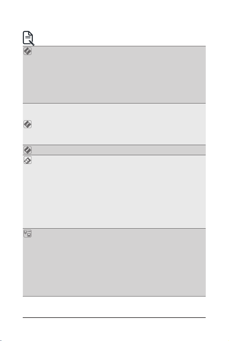
1-3 System Block Diagram
- 17 - Hardware Installation
Page 18

This page intentionally left blank
Hardware Installation - 18 -
Page 19
Chapter 2 System Appearance
1
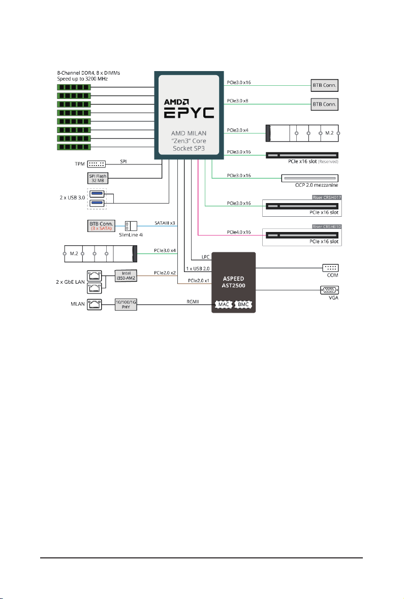
2-1 Front View
HDD0
HDD1
HDD2
No. Decription
1.
• Please Go to Chapter 2-3 Front Panel LED and Buttons for detail description of
function LEDs.
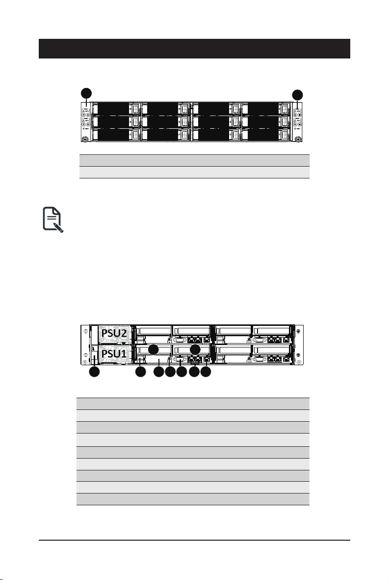
2-2 Rear View
PSU2
PSU1
HDD3
HDD4
HDD5
Front Panel LEDs and Buttons
3
HDD6
HDD7
HDD8
3
HDD9
HDD10
HDD11
1
21
No. Decription
1. CMC LAN Port
2. USB 3.0 Port x 2
3.
PCIe Card Slot x 2
4. Mezzanine Card Slot (Optional/ OCP 2.0)
5. ID LED
6. VGA Port
7. GbE LAN Port x 2
8. Server Management LAN Port
64 5 7 8
- 19 - System Appearance
Page 20
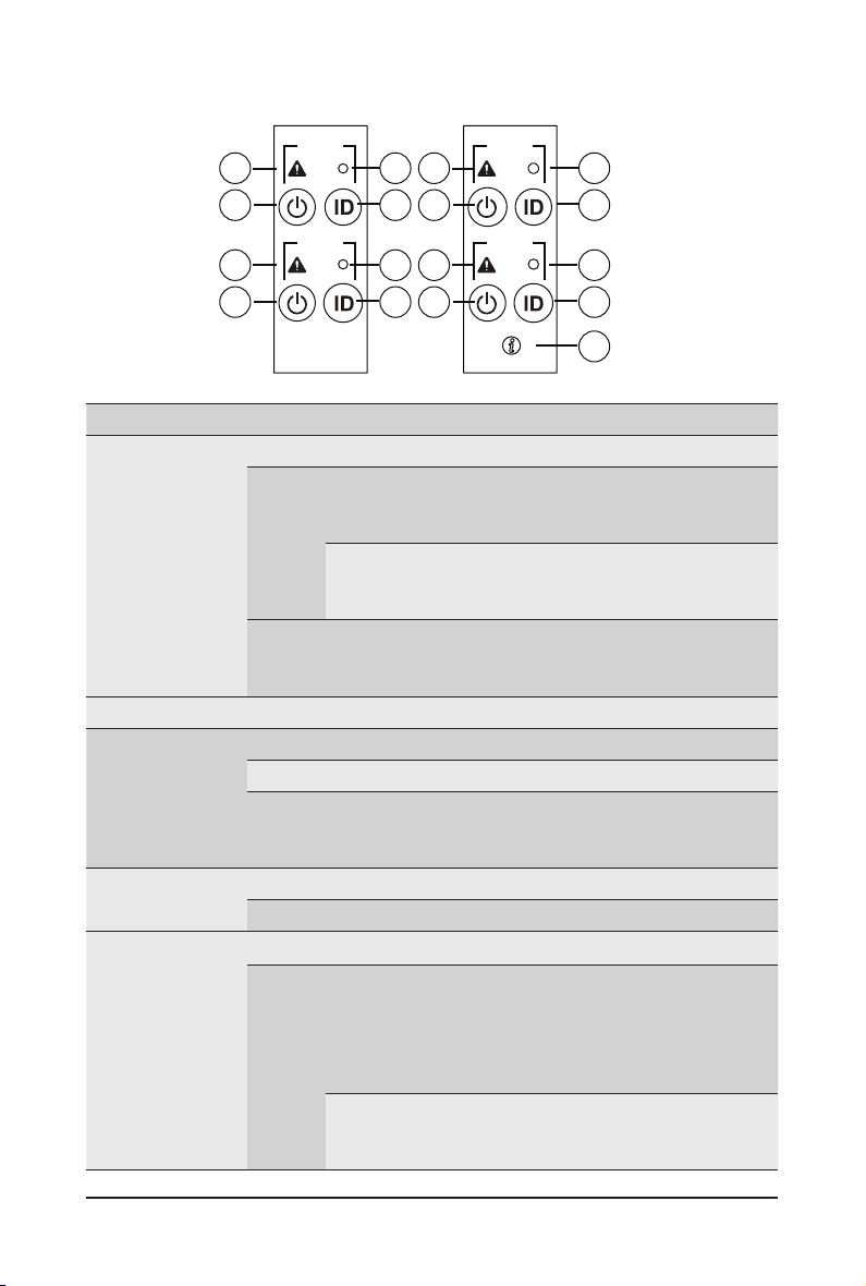
2-3 Front Panel LED and Buttons
NODE1
1
3
1
3
RST
NODE2
RST
2
4
2
4
NODE3
1
3
1
3
RST
NODE4
RST
2
4
2
4
5
No. Name Color Status Description
Green On System is operating normally.
Critical condition, may indicates:
On
System fan failure
System
1.
Status LED
Reset Button -- -- Press this button to reset the system.
2.
Power button
3.
with LED
ID Button
4.
with LED
Enclosure
5.
Status LED
Amber
N/A Off
Green On System is powered on
Green Blink System is in ACPI S1 state (sleep mode)
N/A Off
Blue On System identication is active.
N/A Off System identication is disabled.
Green On System is operating normally.
Amber
System temperature
Non-critical condition, may indicates:
Blink
Redundant power module failure
Temperature and voltage issue
Non-critical condition, may indicates:
Redundant power module failure
Temperature and voltage issue
• System is not powered on or in ACPI S5 state (power
off)
• System is in ACPI S4 state (hibernate mode)
Critical condition, may indicates:
Power module failure
On
System fan failure
Power supply voltage issue
System temperature
Non-critical condition, may indicates:
Blink
Redundant power module failure
Temperature and voltage issue
System Appearance - 20 -
Page 21
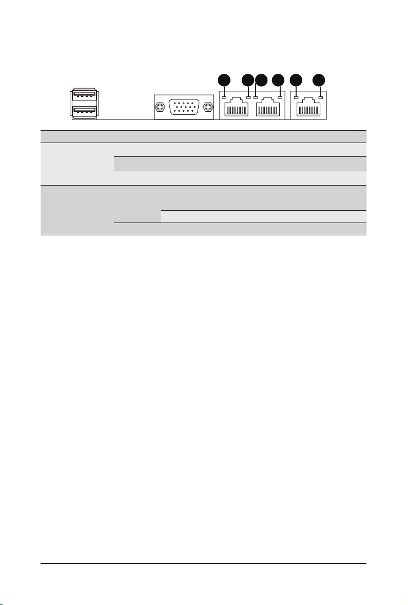
2-4 System LAN LEDs
1 2 1 221
No. Name Color Status Description
Yel l ow On 1Gbps data rate
Green On 100 Mbps data rate
N/A Off 10 Mbps data rate
On Link between system and
Green
Blink Data transmission or receiving is occurring
N/A Off No data transmission or receiving is occurring
network or no access
1.
2.
1GbE
Speed LED
1GbE
Link/
Activity LED
- 21 - System Appearance
Page 22
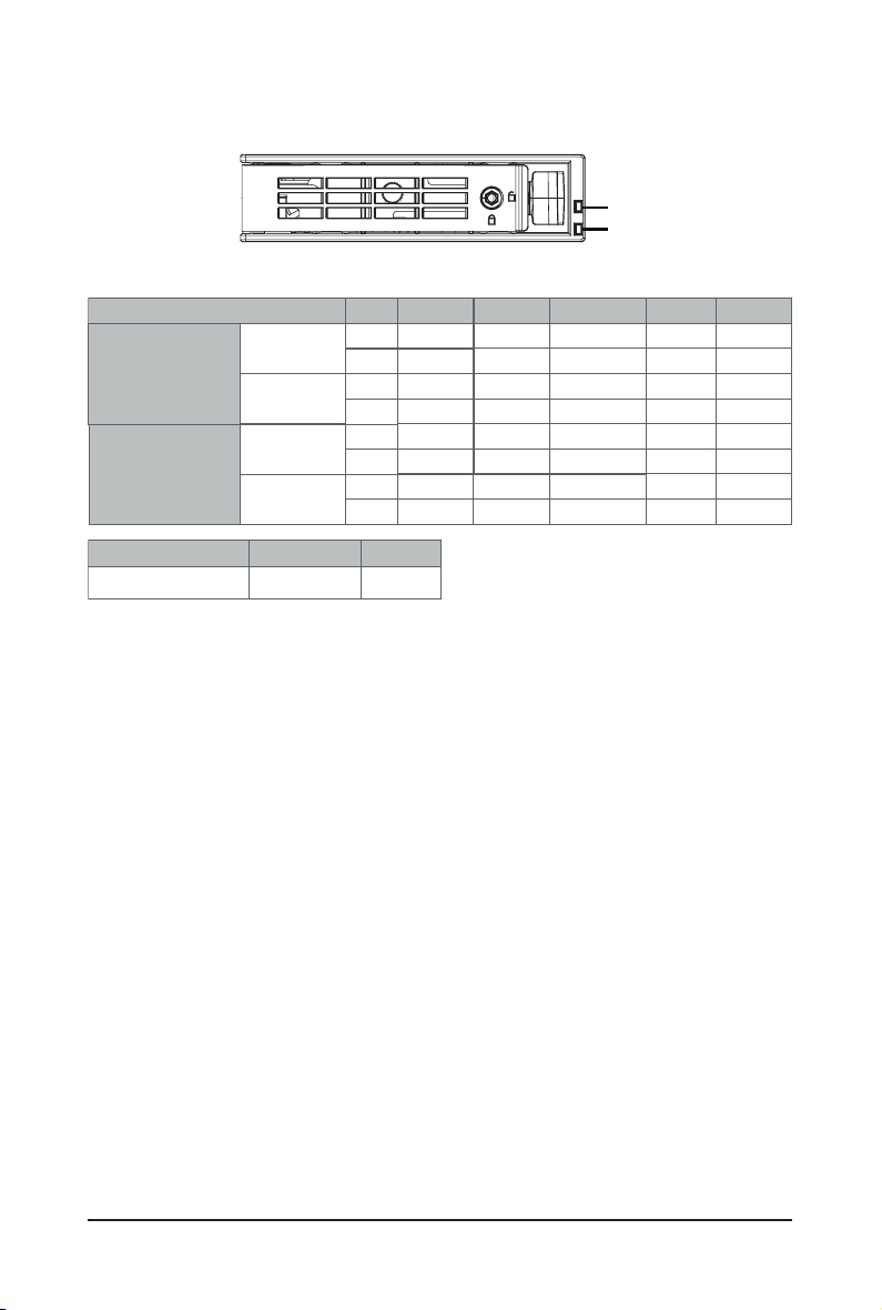
2-5 Hard Disk Drive LEDs
RAID SKU
Disk LED
(LED on
No RAID configuration
(via HBA)
RAID configuration
(via HW RAID Card or
SW RAID Card)
Back Panel)
Removed HDD Slot
(LED on Back Panel)
Disk LED
Removed HDD Slot
LED#1
LED#2
OFF
OFF
OFF
OFF
ON
OFF
ON
Rebuilding
(Low Speed: 2 Hz)
(*3)
(*3)
LED1
Locate
ON(*1)
Green
Amber
ON(*1) OFF --
Green
Amber
Green
Amber
ON(*1)
Green
Amber
HDD Fault
OFF
OFF
ON
OFF
OFF
HDD
Access
BLINK (*2)
OFF
--
--
BLINK (*2)
OFF
--
--
HDD Present
(No Access)
OFF
OFF
--
OFF
OFF
--
--
LED 2
Green
HDD Present No HDD
ON
OFF
NOTE:
*1: Depends on HBA/Utility Spec.
*2: Blink cycle depends on HDD's activity signal.
*3: If HDD is pulled out during rebuilding, the disk status of this HDD is regarded as faulty.
System Appearance - 22 -
Page 23
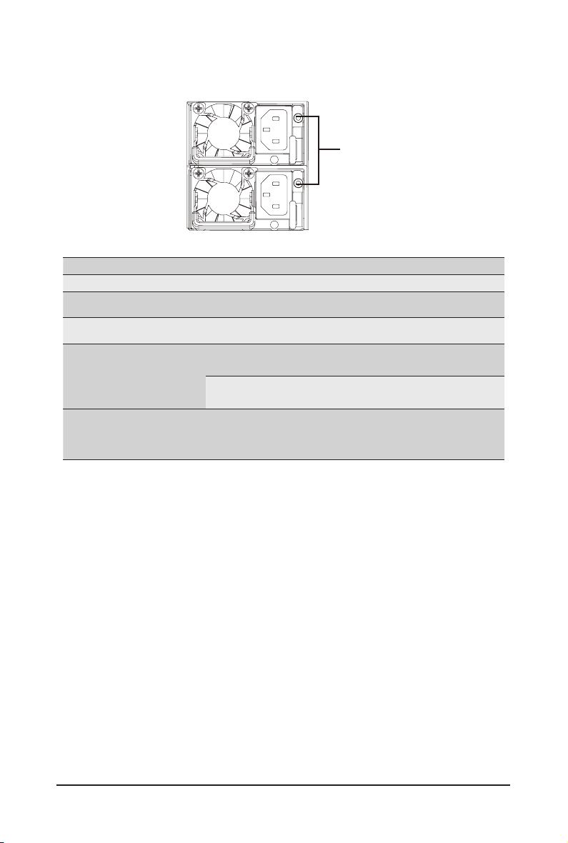
2-6 Power Supply Unit (PSU) LED
PSU LED
State Description
OFF Indicates no AC power to all power supplies
1Hz Blink GREEN Indicates AC present/ only standby on/ Cold redundant mode
2Hz Blink GREEN Indicates power supply rmware in updating mode
Indicates AC cord unplugged or AC power lost; with a
Amber
1Hz Blink Amber
second power supply in parallel still with AC input power
Indicates power supply critical event causing shut down:
failure, OCP, OVP, Fan Fail, UVP
Indicates power supply warning events where
the power supply continues to operate:
high temp, high power, high current, slow fan
System Appearance - 23 -
Page 24

This page intentionally left blank
System Appearance - 24 -
Page 25

Chapter 3 System Hardware Installation
Pre-installation Instructions
Computer components and electronic circuit boards can be damaged electrostatic discharge.
Working on computers that are still connected to a power supply can be extremely
dangerous. Follow the simple guidelines below to avoid damage to your computer or injury to
yourself.
• Always disconnect the computer from the power outlet whenever you are working inside the
computer case.
• If possible, wear a grounded wrist strap when you are working inside the computer case.
Alternatively, discharge any static electricity by touching the bare metal system of the computer
case, or the bare metal body of any other grounded appliance.
• Hold electronic circuit boards by the edges only. Do not touch the components on the board
unless it is necessary to do so. Do not ex or stress the circuit board.
• Leave all components inside the static-proof packaging until you are ready to use the component
for the installation.
- 23 - System Hardware Installation
Page 26
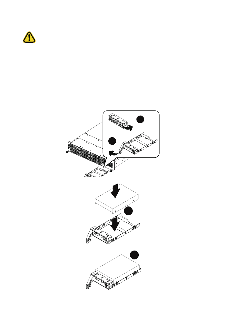
3-1 Installing the Hard Disk Drive
5
Read the following guidelines before you begin to install the Hard disk drive:
• Take note of the drive tray orientation before sliding it out.
• The tray will not t back into the bay if inserted incorrectly.
• Make sure that the HDD is connected to the HDD connector on the backplane.
Follow these instructions to install a 3.5" hard disk drive:
1. Press the release button.
2. Extend the locking lever.
3. Pull the locking lever in the direction indicated to remove the HDD tray.
4. Align the hard disk drive with the positioning stud on the HDD tray.
5. Slide the hard disk drive into the HDD tray.
6. Reinsert the HDD tray into the slot and close the locking lever.
1
2
System Hardware Installation - 24 -
4
Page 27
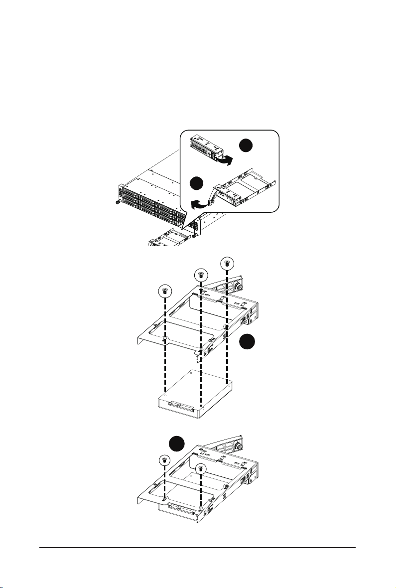
Follow these instructions to install a 2.5" hard disk drive into 3.5" HDD tray:
5
1. Press the release button.
2. Extend the locking lever.
3. Pull the locking lever in the direction indicated to remove the HDD tray.
4. Align the hard disk drive with the positioning stub on the HDD tray.
5. Secure the hard disk drive with ve screws.
6. Reinsert the HDD tray into the slot and close the locking lever.
1
2
4
- 25 - System Hardware Installation
Page 28
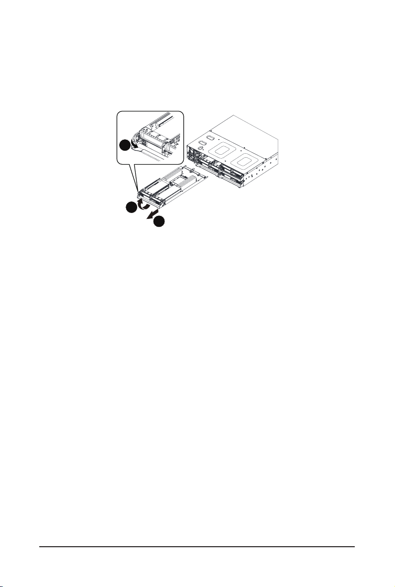
3-2 Removing the Node
Follow these instructions to remove a node:
1. Press the release retaining clip on the right side of the node along the direction of the arrow,
2. Pulling out the node using its handle.
1
Press
2
Pull
3
System Hardware Installation - 26 -
Page 29
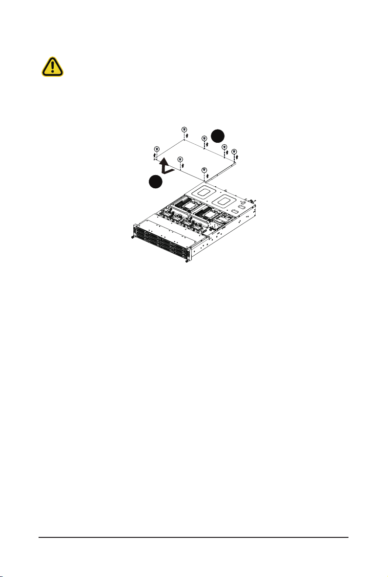
3-3 Removing Chassis Cover
Before you remove or install the system cover
• Make sure the system is not turned on or connected to AC power.
Follow these instructions to remove the system cover:
1. Loosen and remove the seven screws securing the middle cover.
2. Slide the cover to the rear of the system and remove the cover in the direction of the arrow.
1
2
- 27 - System Hardware Installation
Page 30
3-4 Removing and Installing the Fan Duct
Follow these instructions to remove/install the fan duct:
1. Remove the four screws securing the fan ducts.
2. Lift up to remove the fan ducts
3. To install the fan duct, align the fan duct with the guiding groove. Push down the fan duct into
chassis until its rmly seats, then install the four screws to secure the fan ducts in place.
1
2
1
System Hardware Installation - 28 -
Page 31

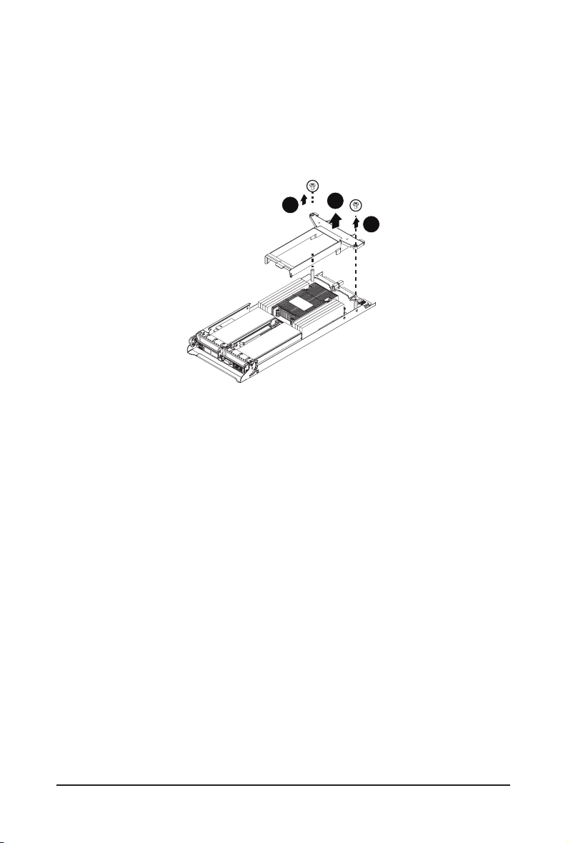
3-5 Removing and Installing the Heatsink
3
Read the following guidelines before you begin to install the heatsink:
• Always turn off the computer and unplug the power cord from the power outlet before
installing the heatsink to prevent hardware damage.
• Unplug all cables from the power outlets.
• Disconnect all telecommunication cables from their ports.
• Place the system unit on a at and stable surface.
• Open the system according to the instructions.
WARNING!
Failure to properly turn off the server before you start installing components may cause seri-
ous damage. Do not attempt the procedures described in the following sections unless you
are a qualied service technician.
Follow these instructions to remove the heatsink:
1. Loosenthecaptivescrews securingtheheatsink inplaceinreverseorder
(4g3g2g1).
2. Liftandremovetheheatsinkfromthesystem.
3. Toreinstall the heat sink reverse steps 1-2 while ensuring that you tighten the
captivescrewsinsequentialorder(1g2g3g4)asseenintheimagebelow.
2
1
4
- 29 - System Hardware Installation
Page 32

3-6 Installing the CPU
External cap
Read the following guidelines before you begin to install the CPU:
• Make sure that the motherboard supports the CPU.
• Always turn off the computer and unplug the power cord from the power outlet before
installing the CPU to prevent hardware damage.
• Unplug all cables from the power outlets.
• Disconnect all telecommunication cables from their ports.
• Place the system unit on a at and stable surface.
• Open the system according to the instructions.
WARNING!
Failure to properly turn off the server before you start installing components may cause seri-
ous damage. Do not attempt the procedures described in the following sections unless you
are a qualied service technician.
Follow these instructions to install the CPU:
1. Loosen the three captive screws in sequential order (1g2g3) securing the CPU cover.
2. Flip open the CPU cover.
3. Remove the CPU cap with CPU from the CPU frame using the handle on the CPU cap.
4. Using the handle on the CPU cap insert the new CPU cap with CPU installed into the CPU frame.
NOTE: Ensure the CPU is installed in the CPU cap in the correct orientation, with the gold triangle
on the CPU aligned to the top left corner of the CPU cap.
5. Flip the CPU frame with CPU installed into place in the CPU socket.
6. Flip the CPU cover into place over the CPU socket.
7. Tighten the CPU cover screws in sequential order (1g2g3) to secure the CPU cover in place.
1
2
1
3
6
• When installing the heat sink over the CPU, use T30-Lobe driver to tighten the 4 captive nuts
in sequential order (1g2g3g4).
• The screw tightening torque: 8 ± 0.5kgf-cm (17.0± 1.0 lbf-in)
System Hardware Installation - 30 -
3
CPU
4
2
5
7
2
3
1
Page 33

3-7 Installing Memory
Read the following guidelines before you begin to install the memory:
• Make sure that the motherboard supports the memory. It is recommended that memory of
the same capacity, brand, speed, and chips be used.
• Always turn off the computer and unplug the power cord from the power outlet before
installing the memory to prevent hardware damage.
• Memory modules have a foolproof design. A memory module can be installed in only one
direction. If you are unable to insert the memory, switch the direction.
3-7-1 Eight Channel Memory Conguration
This motherboard provides 8 DDR4 memory sockets and supports Eight Channel Technology. After the
memory is installed, the BIOS will automatically detect the specifications and capacity of the memory.
Enabling eight Channel memory mode will be eight times of the original memory bandwidth.
DIMM_P0_D0
DIMM_P0_C0
DIMM_P0_B0
DIMM_P0_A0
21
CPU
DIMM_P0_E0
DIMM_P0_F0
DIMM_P0_G0
DIMM_P0_H0
- 31 - System Hardware Installation
Page 34

3-7-2 Installing the Memory
Before installing a memory module, make sure to turn off the computer and unplug the power
cord from the power outlet to prevent damage to the memory module.
Be sure to install DDR4 DIMMs on this motherboard.
Follow these instructions to install the Memory:
1. Insert the DIMM memory module vertically into the DIMM slot, and push it down.
2. Close the plastic clip at both edges of the DIMM slots to lock the DIMM module.
3. Reverse the installation steps when you want to remove the DIMM module.
2
1
2
3-7-3 Processor and Memory Module Matrix Table
Processor and Memory Module Matrix Table
CPU#
Channel A/I Channel B/J Channel C/K Channel D/L Channel E/M Channel F/N Channel G/O Channel H/P
8 DIMMs
CPU0 A1 B1 C1 D1 E1 F1 G1 H1
16 DIMMs
CPU0 A1A0 B1B0 C1C0 D1D0 E1E0 F1F0 G1G0 H1H0
16 DIMMs
CPU0 A1 B1 C1 D1 E1 F1 G1 H1
CPU1 I1 J1 K1 L1 M1 N1 O1 P1
32 DIMMs
CPU0 A1 B1 C1 D1 E1 F1 G1 H1A0 B0 C0 D0 E0 F0 G0 H0
CPU1 I1 J1 K1 L1 M1 N1 O1 P1I0 J0 K0 L0 M0 N0 O0 P0
System Hardware Installation - 32 -
Page 35

3-7-4 Memory Population Table
• When only one DIMM is used, it must be populated in memory slot DIMM1.
EPYC Memory Speed based on DIMM Population (One DIMM per Channel)
DIMM
Typ e
RDIMM
LRDIMM
DIMM Population
DIMM 0
1R(1Rank) 3200
2Ror2DR(2Ranks) 3200
4DR(4Ranks) 3200
2S2R(4Ranks) 3200
2S4R(8Ranks) 3200
Max EPYC 7003
DDR Frequency (MHz)
EPYC Memory Speed based on DIMM Population (Two DIMM per Channel)
DIMM
Typ e
RDIMM
LRDIMM
DIMM Population
DIMM 0 DIMM 1
-- 1R 3200
1R 1R 2933
-- 2Ror2DR 3200
1R 2Ror2DR 2933
2Ror2DR 2Ror2DR 2933
-- 4DR 3200
4DR 4DR 2933
-- 2S2R(4Ranks) 3200
-- 2S4R(8Ranks) 3200
2S2R(4Ranks) 2S2R(4Ranks) 2933
Max EPYC 7003
DDR Frequency (MHz)
- 33 - System Hardware Installation
Page 36

3-8 Installing the PCI Expansion Card
• Voltages can be present within the server whenever an AC power source is connected.
This voltage is present even when the main power switch is in the off position. Ensure
that the system is powered-down and all power sources have been disconnected from the
server prior to installing a PCI card.
Failure to observe these warnings could result in personal injury or damage to equipment.
• The PCI riser assembly does not include a riser card or any cabling as standard. To install
a PCI card, a riser card must be installed.
Follow these instructions to install the left PCI Expansion card:
1. Remove the ve screws securing the riser bracket to the system.
2. Remove the the screw securing the riser bracket to the system.
3. Lift up the riser bracket out of system.
4. Align the PCIe card to the riser guide slot and push in the direction of the arrow until the PCIe card
sits in the PCI card connector.
5. Secure the PCIe card with a screw.
6. Reverse steps 1 - 3 to install the riser bracket back into the system.
1
1
2
System Hardware Installation - 34 -
3
Page 37

2
1
3
5
4
- 35 - System Hardware Installation
Page 38

Follow these instructions to install the right PCI Expansion card:
1. Remove the two screws on the riser bracket to the system.
2. Lift up the riser bracket out of system.
3. Remove the screw securing the side bracket to the riser bracket.
4. Remove the side bracket
5. Align the PCIe card to the riser guide slot and push in the direction of the arrow until the PCIe card
sits in the PCI card connector.
6. Secure the PCIe card with a screw.
7. Install the side bracket to the riser bracket.
8. Secure the side bracket to the riser bracket with a screw.
9. Reverse steps 1 - 2 to install the riser bracket back into the system.
1
1
3
2
2
1
3
5
System Hardware Installation - 36 -
4
Page 39

3-9 Installing the M.2 Device and Heat Sink
WARNING:
Installation of the thermal pad over the M.2 device is required when installing an M.2 device.
Lack of the thermal pad may result in system overheat and throttle the system performance.
CAUTION
The position of the stand-off screw will depend on the size of the M.2 device. The stand-off screw
is pre-installed for 22110 cards as standard. Refer to the size of the M.2 device and change the
position of the stand-off screw accordingly.
Follow these instructions to install the M.2 device and heat sink:
1. Insert the M.2 device into the M.2 connector.
2. Press down on the M.2 device.
3. Install the thermal pad of the M.2 device to the M.2 device.
4. Press down on the thermal pad.
5. Secure the M.2 device and its thermal pad to the motherboard with a single screw.
6. Reverse steps 1-4 to remove the M.2 device.
2
4
3
1
5
- 37 - System Hardware Installation
Page 40

3-10 Replacing the Fan Module
Follow these instructions to replace the fan assembly:
1. Lift up the fan assembly from the chassis.
2. Reverse the previous steps to install the replacement fan assembly.
System Hardware Installation - 38 -
Page 41

3-11 Replacing the Power Supply
Follow these instructions to replace the power supply:
1. Pull up the power supply handle and press the retaining clip on the right side of the power supply
along the direction of the arrow. At the same time, pull out the power supply by using its handle.
2. Insert the replacement power supply rmly into the chassis. Connect the AC power cord to the
replacement power supply.
3
2
1
- 39 - System Hardware Installation
Page 42

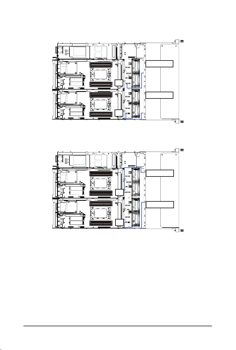
3-12 Cable Routing
Front Panel IO
Rear LAN
System Hardware Installation - 40 -
Page 43

HDD Back Plane Board Power (Top/Bottom Middle Board)
HDD Back Plane Board Signal
- 41 - System Hardware Installation
Page 44
On-Board SATA (Top)
On-Board SATA (Bottom)
SL4_SAS_3
S3
SL4_SAS_1
S1
SL4_SAS_4
S4
S2
System Hardware Installation - 42 -
SL4_SAS_2
Page 45

Chapter 4 Motherboard Components
4-1 Motherboard Components
18
1
19
DIMM_P0_D0
DIMM_P0_C0
DIMM_P0_B0
DIMM_P0_A0
1718
16
2
3
4
5
6
7
19
21
20
21
22
9
8
Item Description
1 USB 3.0 Port x 2
2 ID LED
3 IPMB Connector
4 VGA Port
5 Serial Port Cable Connector
6 GbE LAN Port x 2
7 Server Management LAN Port
8 M.2 Connector (PCIe3 x4, Supports NGFF-22110)
9 M.2 Connector (PCIe3 x4, Supports NGFF-22110)
10 SlimLine SAS Connector (SL_SATA1/SATA)
11 SGPIO Connector
12 Power & PCIe/SATA Connector
13 Power & PCIe/SATA Connector
14 TPM Module Connector (SPI Inter face)
15 SGPIO Connector
16 Power & PCIe/SATA Connector
17 Proprietary PCIe x16 Slot (Gen3 x16)
18 Riser Slot #1
19 OCP Mezzanine Connector (OCP 2.0/Gen3 x16)
20 Riser Slot #2
21 System Battery Power Cable Connector
22 SlimLine SAS Connector (SL_SATA0/SATA)
CPU
DIMM_P0_E0
DIMM_P0_F0
DIMM_P0_G0
DIMM_P0_H0
15
13
14
11
12
10
- 43 - Motherboard Components
Page 46

4-2 Jumper Setting
21
Clear CMOS
CLR_CMOS
321
Default Enable
NCSI Switch
ON
OFF
21
OCP Mezzanine
Onboard LAN
-
21',3
Motherboard Components - 44 -
Page 47

Chapter 5 BIOS Setup
BIOS (Basic Input and Output System) records hardware parameters of the system in the EFI on the
motherboard. Its major functions include conducting the Power-On Self-Test (POST) during system startup,
saving system parameters and loading operating system, etc. BIOS includes a BIOS Setup program that
allows the user to modify basic system conguration settings or to activate certain system features. When the
power is turned off, the battery on the motherboard supplies the necessary power to the CMOS to keep the
conguration values in the CMOS.
To access the BIOS Setup program, press the <DEL> key during the POST when the power is turned on.
• BIOS ashing is potentially risky, if you do not encounter problems of using the current BIOS
version, it is recommended that you don't ash the BIOS. To ash the BIOS, do it with caution.
Inadequate BIOS ashing may result in system malfunction.
• It is recommended that you not alter the default settings (unless you need to) to prevent system
instability or other unexpected results. Inadequately altering the settings may result in system's
failure to boot. If this occurs, try to clear the CMOS values and reset the board to default values.
(Refer to the Exit section in this chapter or introductions of the battery/clearing CMOS jumper in
Chapter 4 for how to clear the CMOS values.)
BIOS Setup Program Function Keys
<f><g> Move the selection bar to select the screen
<h><i> Move the selection bar to select an item
<+> Increase the numeric value or make changes
<-> Decrease the numeric value or make changes
<Enter> Execute command or enter the submenu
<Esc> Main Menu: Exit the BIOS Setup program
Submenus: Exit current submenu
<F1> Show descriptions of general help
<F3> Restore the previous BIOS settings for the current submenus
<F9> Load the Optimized BIOS default settings for the current submenus
<F10> Save all the changes and exit the BIOS Setup program
- 45 - BIOS Setup
Page 48

Main
This setup page includes all the items in standard compatible BIOS.
Advanced
This setup page includes all the items of AMI BIOS special enhanced features.
(ex: Auto detect fan and temperature status, automatically congure hard disk parameters.)
AMD CBS
This setup page includes the common items for conguration of AMD motherboard-related information.
AMD PBS Option
This setup page includes the common items for conguration of AMD CPM RAS related settings.
Chipset
This setup page includes all the submenu options for conguring the function of processor, network,
main chipset, and system event logs.
Server Management
Server additional features enabled/disabled setup menus.
Security
Change, set, or disable supervisor and user password. Conguration supervisor password allows you to
restrict access to the system and BIOS Setup.
A supervisor password allows you to make changes in BIOS Setup.
A user password only allows you to view the BIOS settings but not to make changes.
Boot
This setup page provides items for conguration of boot sequence.
Save & Exit
Save all the changes made in the BIOS Setup program to the CMOS and exit BIOS Setup. (Pressing
<F10> can also carry out this task.)
Abandon all changes and the previous settings remain in effect. Pressing <Y> to the confirmation
message will exit BIOS Setup. (Pressing <Esc> can also carry out this task.)
BIOS Setup - 46 -
Page 49

5-1 The Main Menu
Once you enter the BIOS Setup program, the Main Menu (as shown below) appears on the screen. Use
arrow keys to move among the items and press <Enter> to accept or enter other sub-menu.
Main Menu Help
The on-screen description of a highlighted setup option is displayed on the bottom line of the Main Menu.
Submenu Help
While in a submenu, press <F1> to display a help screen (General Help) of function keys available for the
menu. Press <Esc> to exit the help screen. Help for each item is in the Item Help block on the right side of
the submenu.
• When the system is not stable as usual, select the Restore Defaults item to set your system
to its defaults.
• The BIOS Setup menus described in this chapter are for reference only and may differ by
BIOS version.
- 47 - BIOS Setup
Page 50

Parameter Description
BIOS Information
Project Name Displays the project name information.
Project Version Displays version number of the BIOS setup utility.
Build Date and Time Displays the date and time when the BIOS setup utility was created.
BMC Information
BMC Firmware Version Displays version number of the BIOS setup utility.
Processor Information
CPU 0 Brand String / CPU 1 Brand
String / CPU Speed / Processor
Core / Microcode Patch
BIOS Setup - 48 -
Displays the technical information for the installed processor(s).
Page 51

Parameter Description
Total Memory
Memory Speed
(Note1)
(Note1)
Displays the total memory size of the installed memory.
Displays the frequency information of the installed memory.
VR Information
Version Displays VR version information.
AGESA PI Version
PI Version Displays AGESA PI version information.
Onboard LAN Information
LAN1 MAC Address
LAN2 MAC Address
(Note2)
(Note2)
Displays LAN MAC address information.
Displays LAN MAC address information.
System Date Sets the date following the weekday-month-day-year format.
System Time Sets the system time following the hour-minute-second format.
(Note1) The number of LAN ports listed will depend on the motherboard / system model.
(Note2) This section will display capacity and frequency information of the memory that the customer has
installed.
- 49 - BIOS Setup
Page 52

5-2 Advanced Menu
The Advanced menu display submenu options for conguring the function of various hardware components.
Select a submenu item, then press [Enter] to access the related submenu screen.
BIOS Setup - 50 -
Page 53

5-2-1 Trusted Computing
Parameter Description
Conguration
Security Device Support
SPI TPM Support Options available: Enabled/Disabled. Default setting is Enabled
Select Enable to activate TPM support feature.
Options available: Enable/Disable. Default setting is Enable.
- 51 - BIOS Setup
Page 54

5-2-2 PSP Firmware Versions
The PSP Firmware Versions page displays the basic PSP rmware version information. Items on this window
are non-congurable.
BIOS Setup - 52 -
Page 55

5-2-3 Legacy Video Select
Parameter Description
OnBrd/Ext VGA Select
Select between onboard or external VGA support.
Options available: Auto/Onboard/External. Default setting is Onboard.
- 53 - BIOS Setup
Page 56

5-2-4 AST2500 Super IO Conguration
Parameter Description
AST2500 Super IO Conguration
Super IO Chip Displays the super IO chip information.
BIOS Setup - 54 -
Page 57

Parameter Description
Press [Enter] to congure advanced items.
Serial Port
– Enable/Disable the Serial Port (COM). When set to Enabled allows
you to congure the Serial port 1/2 settings. When set to Disabled,
displays no conguration for the serial port.
– Options available: Enabled/Disabled. Default setting is Enabled.
Devices Settings
– Displays the serial port 1/2 device settings.
Change Settings
– Select an optimal setting for the Super I/O device:
– Options available for Serial Port 1:
Auto
IO=3F8h; IRQ=4;
Serial Port 1/2
Conguration
IO=3F8h; IRQ=3, 4, 5, 6, 7, 9, 10, 11, 12;
IO=2F8h; IRQ=3, 4, 5, 6, 7, 9, 10, 11, 12;
IO=3E8h; IRQ=3, 4, 5, 6, 7, 9, 10, 11, 12;
IO=2E8h; IRQ=3, 4, 5, 6, 7, 9, 10, 11, 12;
Default setting is Auto.
Options available for Serial Port 2:
Auto
IO=2F8h; IRQ=3;
IO=3F8h; IRQ=3, 4, 5, 6, 7, 9, 10, 11, 12;
IO=2F8h; IRQ=3, 4, 5, 6, 7, 9, 10, 11, 12;
IO=3E8h; IRQ=3, 4, 5, 6, 7, 9, 10, 11, 12;
IO=2E8h; IRQ=3, 4, 5, 6, 7, 9, 10, 11, 12;
Default setting is Auto.
(Note1)
:
(Note2)
(Note2)
:
:
(Note1) Advanced items will appear when this item is set to Enabled.
(Note2) This item will appear when Serial Port is set to Enabled.
- 55 - BIOS Setup
Page 58

5-2-5 S5 RTC Wake Settings
Parameter Description
Enable or disable system wake on alarm event. Select Fixed Time, system
Wake system from S5
will wake on the time (HH:MM:SS) specied. Select Dynamic Time and the
system will wake at the current time plus an increase in minute(s).
Options available: Disabled/Fixed Time. Default setting is Disabled.
BIOS Setup - 56 -
Page 59

5-2-6 Serial Port Console Redirection
Parameter Description
COM1/SOL / COM2 Console
Redirection
(Note)
Legacy Console Redirection
Serial Port for Out-of-Band
Management / Windows
Emergency Management
Services (EMS) Console
Redirection
(Note)
COM1/SOL / COM2 Console
Redirection Settings
Select whether to enable console redirection for specied device. Console
redirection enables the users to manage the system from a remote location.
Options available: Enabled/Disabled. Default setting is Disabled.
Selects a COM port for Legacy serial redirection. The options are
dependent on the available COM ports.
Selects a COM port for EMS console redirection. EMS console redirection
allows the user to congure Console Redirection Settings to support Out-of-
Band Serial Port management.
Options available: Enabled/Disabled. Default setting is Disabled.
Press [Enter] to congure advanced items.
Please note that this item is congurable when COM1/SOL / COM2
Console Redirection is set to Enabled.
Terminal Type
– Selects a terminal type to be used for console redirection.
– Options available: VT100/VT100+/ANSI /VT-UTF8. Default setting
is ANSI.
(Note) Advanced items prompt when this item is set to Enabled.
- 57 - BIOS Setup
Page 60

Parameter Description
Bits per second
– Selects the transfer rate for console redirection.
– Options available: 9600/19200/38400/57600/115200. Default setting
is 115200.
Data Bits
– Selects the number of data bits used for console redirection.
– Options available: 7/8. Default setting is 8.
Parity
– A parity bit can be sent with the data bits to detect some
transmission errors.
– Even: parity bit is 0 if the num of 1's in the data bits is even.
– Odd: parity bit is 0 if num of 1's in the data bits is odd.
– Mark: parity bit is always 1. Space: Parity bit is always 0.
– Mark and Space Parity do not allow for error detection.
– Options available: None/Even/Odd/Mark/Space. Default setting is
None.
Stop Bits
– Stop bits indicate the end of a serial data packet. (A start bit
indicates the beginning). The standard setting is 1 stop bit.
Communication with slow devices may require more than 1 stop bit.
COM1/SOL / COM2 Console
Redirection Settings
(continued)
– Options available: 1/2. Default setting is 1.
Flow Control
– Flow control can prevent data loss from buffer overow. When
sending data, if the receiving buffers are full, a 'stop' signal can
be sent to stop the data ow. Once the buffers are empty, a 'start'
signal can be sent to re-start the ow. Hardware ow control uses
two wires to send start/stop signals.
– Options available: None/Hardware RTS/CTS. Default setting is
None.
VT-UTF8 Combo Key Support
– Enable/Disable the VT-UTF8 Combo Key Support.
– Options available: Enabled/Disabled. Default setting is Enabled.
Recorder Mode
– When this mode enabled, only texts will be send. This is to capture
Terminal data.
– Options available: Enabled/Disabled. Default setting is Disabled.
Resolution 100x31
– Enable/Disable extended terminal resolution.
– Options available: Enabled/Disabled. Default setting is Enabled.
Putty KeyPad
– Selects FunctionKey and KeyPad on Putty.
– Options available: T100/LINUX/XTERMR6/SCO/ESCN/VT400.
– Default setting is VT100.
(Note)
(Note)
(Note)
(Note) Advanced items prompt when this item is dened.
BIOS Setup - 58 -
Page 61

Parameter Description
Redirection COM Port
– Selects a COM port to display redirection of Legacy OS and Legacy
OPROM Messages.
– Options available: COM1/SOL / COM2. Default setting is COM1/
SOL.
Resolution
Legacy Console Redirection
Settings
Serial Port for Out-of-Band
Management / Windows
Emergency Management
Services (EMS) Console
Redirection Settings
– On Legacy OS, the number of rows and columns supported in
redirection.
Options available: 80x24/80x25. Default setting is 80x24.
Redirection After BIOS POST
– This item allows user to enable console redirection after OS has
loaded.
– Options available: Always Enable/Boot Loader. Default setting is
Always Enable.
Out-of-Band Mgmt Port
– Selects a serial port to remotely manage a Windows server OS.
– Options available: COM1/SOL / COM2. Default setting is COM1/
SOL.
Terminal Type
– Selects a terminal type to be used for console redirection.
– Options available: VT100/VT100+/ANSI /VT-UTF8. Default setting
is VT-UTF8.
Bits per second
– Selects the transfer rate for console redirection.
– Options available: 9600/19200/38400/57600/115200. Default setting
is 115200.
Flow Control
– Flow control can prevent data loss from buffer overow. When
sending data, if the receiving buffers are full, a 'stop' signal can
be sent to stop the data ow. Once the buffers are empty, a 'start'
signal can be sent to re-start the ow. Hardware ow control uses
two wires to send start/stop signals.
– Options available: None/Hardware RTS/CTS. Default setting is
None.
- 59 - BIOS Setup
Page 62

5-2-7 CPU Conguration
Parameter Description
CPU Conguration
SVM Mode
SMEE
CPU 0 Information Press [Enter] to view more information related to CPU 0.
Enable/disable the CPU Virtualization.
Options available: Enabled/Disabled. Default setting is Enabled.
Controls the Secure Memory Encryption Enable (SMEE) function.
Options available: Enabled/Disabled. Default setting is Enabled.
BIOS Setup - 60 -
Page 63

5-2-8 PCI Subsystem Settings
- 61 - BIOS Setup
Page 64

Parameter Description
PCI Bus Driver Version Displays the PCI Bus Driver version information.
Change the PCIe lanes.
SLOT1_F / SLOT1_R / SLOT2_F /
SLOT2_R / SLOT3 / OCP1 / OCP2
(Note1)
Lanes
Options available:
Auto / x16 / x8 x8 / x8 x4 x4 / x4 x4 x8 / x4 x4 x4 x4
(OCP2 Lanes only features Auto / x8 / x4 x4.)
Disabled. Default setting is Auto.
SLOT1_F / SLOT1_R / SLOT2_F /
SLOT2_R / SLOT3 / OCP1 / OCP2 I/O
(Note1)
ROM
Onboard LAN Controller
(Note2)
When enabled, this setting will initialize the device expansion
ROM for the related PCI-E slot.
Options available: Enabled/Disabled. Default setting is Enabled.
Enable/Disable the onboard LAN devices.
Options available: Enabled/Disabled. Default setting is Enabled.
Enable/Disable the onboard LAN devices and initializes device
Onboard LAN I/O ROM
(Note2)
expansion ROM.
Options available: Enabled/Disabled. Default setting is Enabled.
PCI Devices Common Settings
Enable/Disable memory mapped I/O to 4GB or greater address
Above 4G Decoding
space (Above 4G Decoding).
Options available: Enabled/Disabled. Default setting is Enabled.
If the system has SR-IOV capable PCIe devices, this item Enable/
SR-IOV Support
Disable Single Root IO Virtualization Support.
Options available: Enabled/Disabled. Default setting is Enabled.
(Note1) This section is dependent on the available PCIe Slot.
(Note2) This section is dependent on the available LAN controller.
BIOS Setup - 62 -
Page 65

5-2-9 USB Conguration
Parameter Description
USB Conguration
USB Module Version Displays the USB version.
USB Controllers Displays the supported USB controllers.
USB Devices Displays the USB devices connected to the system.
Enable/disable the Legacy USB support fuction. AUTO option disables
Legacy USB Support
XHCI Hand-off
USB Mass Storage Driver
(Note)
Support
Port 60/64 Emulation
USB hardware delays and
time-outs
USB transfer time out
legacy support if no USB devices are connected. DISABLE option will
keep USB devices available only for EFI applications.
Options available: Auto/Enabled/Disabled. Default setting is Enabled.
Enable/Disable the XHCI (USB 3.0) Hand-off support.
Options available: Enabled/Disabled. Default setting is Enabled.
Enable/Disable the USB Mass Storage Driver Support.
Options available: Enabled/Disabled. Default setting is Enabled.
Enables the I/O port 60h/64h emulation support. This should be enabled
for the complete USB Keyboard Legacy support for non-USB aware OS.
Options available: Enabled/Disabled. Default setting is Enabled.
The time-out value for Control, Bulk, and Interrupt transfers.
Options available: 1 sec/5 sec/10 sec/20 sec. Default setting is 20 sec.
(Note) This item is present only if you attach USB devices.
- 63 - BIOS Setup
Page 66

Parameter Description
Device reset time-out
Device power-up delay
Mass Storage Devices
AMI Virtual CDROM0 1.00 /
HDisk0 1.00
USB mass storage device Start Unit command time-out.
Options available: 10 sec/20 sec/30 sec/40 sec. Default setting is 20 sec.
Maximum time the device will take before it properly reports itself to the
Host Controller. "Auto" uses default value: for a Root port it is 100 ms, for
a Hub port the delay is taken from Hub descriptor.
Options available: Auto/Manual. Default setting is Auto.
Mass storage device emulation type. AUTO enumerates devices
according to their media format. Optical drives are emulated as CDROM,
drives with no media will be emulated according to a drive type.
Options available: Auto/Floppy/Forced FDD/Hard Disk/CD-ROM. Default
setting is Auto.
BIOS Setup - 64 -
Page 67

5-2-10 NVMe Conguration
Parameter Description
NVMe controller and Drive
Information
Displays the NVMe devices connected to the system.
- 65 - BIOS Setup
Page 68

5-2-11 SATA Conguration
BIOS Setup - 66 -
Page 69

5-2-12 Network Stack Conguration
Parameter Description
Network Stack
Ipv4 PXE Support
Ipv4 HTTP Support
Ipv6 PXE Support
Ipv6 HTTP Support
IPSEC Certicate
PXE boot wait time
Media detect count
(Note)
(Note)
(Note)
(Note)
(Note)
(Note)
(Note)
Enable/Disable the UEFI network stack.
Options available: Enabled/Disabled. Default setting is Enabled.
Enable/Disable the Ipv4 PXE feature.
Options available: Enabled/Disabled. Default setting is Enabled.
Enable/Disable the Ipv4 HTTP feature.
Options available: Enabled/Disabled. Default setting is Disabled.
Enable/Disable the Ipv6 PXE feature.
Options available: Enabled/Disabled. Default setting is Disabled.
Enable/Disable the Ipv6 HTTP feature.
Options available: Enabled/Disabled. Default setting is Disabled.
Enable/Disable the IPSEC Certicate feature.
Wait time in seconds to press ESC key to abort the PXE boot.
Press the <+> / <-> keys to increase or decrease the desired values.
Number of times the presence of media will be checked.
Press the <+> / <-> keys to increase or decrease the desired values.
(Note) This item appears when Network Stack is set to Enabled.
- 67 - BIOS Setup
Page 70

5-2-13 UEFI POST LOGO Conguration
Parameter
UEFI Conguration
Output Device Type
BIOS Setup - 68 -
Description
Select output device.
Options available: First loaded Device,Onboard Device,External Device,
Specic Device.
Default setting is Onboard Deviceevice.
Page 71

5-2-14 AMD Mem Conguration Status
Parameter Description
Press [Enter] for conguration of advanced items.
Channel A/BC/D/E/F/G/H
– DIMM0 Presence
CPU 0
– DIMM1 Presence
– Chipset/Bank Interleave
Dram EC
Dram Parity
Dimm Sensor Fine Grain Mode
- 69 - BIOS Setup
Page 72

5-2-15 Tls Auth Conguration
Parameter Description
Press [Enter] for conguration of advanced items.
Enroll Cert
– Press [Enter] to enroll a certicate
Server CA Conguration
– Commit Changes and Exit
– Discard Changes and Exit
Delete Cert
Client Cert Conguration N/A
• Enroll Cert Using File
• Cert GUID
Input digit character in 1111111-2222-3333-44441234567890ab format.
BIOS Setup - 70 -
Page 73

5-2-16 Intel(R) I350 Gigabit Network Connection
- 71 - BIOS Setup
Page 74

Parameter Description
Press [Enter] to congure advanced items.
Link Speed
– Allows for automatic link speed adjustment.
– Options available: Auto Negotiated/10 Mbps Half/10 Mbps Full/100
Mbps Half/100 Mbps Full. Default setting is Auto Negotiated.
NIC Conguration
Blink LEDs
UEFI Driver Displays the technical specications for the Network Interface Controller.
Adapter PBA Displays the technical specications for the Network Interface Controller.
Device Name Displays the technical specications for the Network Interface Controller.
Chip Type Displays the technical specications for the Network Interface Controller.
PCI Device ID Displays the technical specications for the Network Interface Controller.
PCI Address Displays the technical specications for the Network Interface Controller.
Link Status Displays the technical specications for the Network Interface Controller.
MAC Address Displays the technical specications for the Network Interface Controller.
Virtual MAC Address Displays the technical specications for the Network Interface Controller.
Wake On LAN
– Enables power on of the system via LAN. Note that conguring
Wake on LAN in the operating system does not change the value of
this setting, but does override the behavior of Wake on LAN in OS
controlled power states.
– Options available: Enabled/Disabled. Default setting is Enabled.
Identies the physical network port by blinking the associated LED.
Press the numeric keys to adjust desired values.
BIOS Setup - 72 -
Page 75

5-2-17 VLAN Conguration
- 73 - BIOS Setup
Page 76

Parameter Description
Press [Enter] to congure advanced items.
Create new VLAN
VLAN ID
– Sets VLAN ID for a new VLAN or an existing VLAN.
– Press the <+> / <-> keys to increase or decrease the desired values.
The valid range is from 0 to 4094.
Priority
– Sets 802.1Q Priority for a new VLAN or an existing VLAN.
Enter Conguration Menu
– Press the <+> / <-> keys to increase or decrease the desired values.
The valid range is from 0 to 7.
Add VLAN
– Press [Enter] to create a new VLAN or update an existing VLAN.
Congured VLAN List
– Enable/Disable the VLAN.
– Options available: Enable/Disable. Default setting is Disabled.
Remove VLAN
– Press [Enter] to remove an existing VLAN.
(Note) Only Supported when Congured VLAN List is set to Enabled.
BIOS Setup - 74 -
Page 77

5-2-18 MAC IPv4 Network Conguration
Parameter Description
Congured
Enable DHCP
Local IP Address
Local NetMask
Local Gateway
Local DNS Servers
(Note)
(Note)
(Note)
(Note)
(Note)
Save Changes and Exit Press [Enter] and then choose to save or discard the changes made.
Indicates whether network address is congured successfully or not.
Options available: Disabled/Enabled. Default setting is Disabled.
Options available: Enabled/Disabled. Default setting is Enabled.
Press [Enter] to congure local IP address.
Press [Enter] to congure local NetMask.
Press [Enter] to congure local Gateway
Press [Enter] to congure local DNS servers
(Note) This item will appear on the screen when Congured is set to Enabled.
- 75 - BIOS Setup
Page 78

5-2-19 MAC IPv6 Network Conguration
Parameter Description
Press [Enter] for conguration of advanced items.
Interface Name
Interface Type
MAC address
Host address
Route Table
Gateway addresses
DNS addresses
Enter Conguration Menu
Interface ID
– The 64-bit alternative interface ID for the device. The string is
colon separated e.g. ff:dd:88:66:cc:1:2:3.
DAD Transmit Count
– The number of consecutive Neighbor Solicitaion messages sent
while performing Duplicate Address Detection on a tentative
address. A value of zero indicates that Duplicate Addres Detection
is not performed.
Policy
Save Changes and Exit
BIOS Setup - 76 -
Page 79

5-3 AMD CBS Menu
AMD CBS menu displays submenu options for configuring the CPU-related information that the BIOS
automatically sets. Select a submenu item, then press [Enter] to access the related submenu screen.
- 77 - BIOS Setup
Page 80

5-3-1 CPU Common Options
Parameter Description
Valhalla Common Options
Press [Enter] for more options.
Custom Core Pstates
– Allows you to accept or decline custom core pstates. When
Performance
Prefetcher settings
Core Watchdog
CCD/Core/Thread Enablement
– Allows you to accept or decline enabling CCDs, processor cores
Press [Enter] for more options.
L1 Stream HW Prefetcher
– Option to enable or disable L1 Stream HW Prefetcher
– Options available: Disable/Enable/Auto. Default option is Auto.
L2 Stream HW Prefetcher
– Option to enable or disable L2 Stream HW Prefetcher
– Options available: Disable/Enable/Auto. Default option is Auto.
Press [Enter] for more options.
Core Watchdog Timer Enable
– Enable or disable CPU watchdog timer.
– Options available: Disable/Enable/Auto. Default option is Auto.
accepted you can disable or customize ceratin pstates.
and threads. When accepted you can control the number of CCDs
to be used, the number of cores to be used, and whether to enable
or disable symmetric multithreading.
BIOS Setup - 78 -
Page 81

Parameter Description
From a workaroud for GCC/C000005 issue for XV Core on CZ A0,
RedirectForReturnDis
Platform First Error Warning
Core Performance Boost
Global C-State Control
Power Supply Idle Control
Opcache Control
SEV ASID Count
SEV-ES ASID Space Limit
Control
Streaming Stores Control
Local APIC Mode
ACPI_CST C1 Decaration
MCA error thresh enable
SMU and PSP Debug Mode
setting MSRC001_1029 Decode Conguration (DE_CFG) bit 14
[DecfgNoRdrctForReturns] to 1.
Options available: Auto/1/0. Default option is Auto.
Enable/Disable PFEH, cloak individual banks, and mask deferred error
interrupts from each bank.
Options available: Enabled/Disabled/Auto. Default option is Enabled.
Allows you to disable CPB.
Options available: Disabled/Auto. Default option is Auto.
Controls the IO based C-state generation and DF C-states.
Options available: Disabled/Enabled/Auto. Default option is Auto.
Congures the power supply idle control.
Options available: Low Current Idle/Typical current Idle/Auto. Default
option is Auto.
Enables or disables the Opcache.
Options available: Disabled/Enabled/Auto. Default option is Auto.
This eld species the max. valid ASID, which affects the maximum
system physical address space. 16TB of physical address space is
available for systems that support 253 ASIDs, while 8TB of physical
address space is available for systems that support 509 ASIDs.
Options available: 253 ASIDs/509 ASIDs/Auto. Default option is Auto.
Space limit control for SEV-ES ASIDs.
Options available: Auto/Manual. Default option is Auto.
Enables or disables the streaming stores functionality.
Options available: Disabled/Enabled/Auto. Default option is Auto.
Sets the Local APIC mode.
Options available: xAPIC/x2APIC/Auto. Default option is Auto.
Determines whether or not to declare the C1 state to the OS.
Options available: Disabled/Enabled/Auto. Default option is Auto.
Enable MCA error thresholding.
Options available: False/True/Auto. Default option is Auto.
When this option is enabled, specic uncorrected errors detected by the
PSP FW or SMU FW will hand and not reset the system.
Options available: Disabled/Enabled/Auto. Default option is Auto.
- 79 - BIOS Setup
Page 82

Parameter Description
By default (Auto) the bronze workaround is applied.
Bronze workaround: DbReq and PDM function as expected, breakpoint
redirect capability compromised.
Xtrig7 Workaround
PPIN Opt-in
Silver workaround: DbReq, PDM, and breakpoint redirect function as
expected, SCAN capability compromised.
Options available: Auto/No Workaround/Bronze Workaround/Silver
Workaround. Default option is Auto.
Turns on PPIN feature.
Options available: Disabled/Enabled/Auto. Default option is Auto.
BIOS Setup - 80 -
Page 83

5-3-2 DF Common Options
Parameter Description
Press [Enter] for conguration of advanced items.
DRAM scrub time
– Provides a value that is the number of hours to scrub memory.
– Options available: Disabled/1 hour/4 hours/8 hours/16 hours/24
Poison scrubber control
Scrubber
– Allows you to enable or disable poison scrubber control.
– Options available: Disabled/Enabled/Auto. Default option is Auto.
Redirect scrubber control
– Allows you to enable or disable redirect of scrubber control.
– Options available: Disabled/Enabled/Auto. Default option is Auto.
Redirect scrubber limit
– Allows you to set the redirect scrubber limit.
– Options available: 2/4/8/Innite/Auto. Default option is Auto.
hours/48 hours/Auto. Default option is Auto.
- 81 - BIOS Setup
Page 84

Parameter Description
Press [Enter] for more options.
NUMA notes per socket
– Species the number of desired NUMA (Non-uniform Memory
Access) notes per socket. Zero will attempt to interleave the two
sockets together.
– Options available: NPS0/NPS1/NPS2/NPS4/Auto. Default option
is Auto.
Memory interleaving
– Allows for disabling memory interleaving. Note that NUMA nodes
per socket will be honored regardless of this setting.
– Options available: Disabled/Auto. Default option is Auto.
Memory interleaving size
– Controls the memory interleaving size. The valid value are AUTO,
Memory Addressing
ACPI
256 bytes, 512 bytes, 1Kbytes or 2Kbytes. This determines the
starting address of the interleave (bit 8, 9, 10 or 11).
– Options available: 256 Bytes/512 Bytes/1 KB/2KB/Auto. Default
setting is Auto.
1TB remap
– Attempt to remap DRAM out of the space just below the 1TB
boundary. The ability to remap depends on DRAM conguration,
NPS, and interleaving selection, and may not always be possible.
– Options available: Do not remap/Attempt to remap.Auto. Default
option is Auto.
DRAM map inversion
– Inverting the map will cause the highest memory channels to get
assigned the lowest addresses in the system.
– Options available: Disabled/Enabled/Auto. Default option is Auto.
Press [Enter] for more options.
ACPI SRAT L3 Cache as NUMA Domain
– Enabled: Each CCX in the system will be declared as a separate
NUMA domain.
– Disabled: Memory Addressing \ NUMA nodes per socket will be
declared.
– Options available: Disable/Enable/Auto. Default option is Auto.
ACPI SLIT Distance Control
– Determines how the SLIT distances are declared.
– Options available: Manual/Auto. Default option is Auto.
ACPI SLIT remote relative distance
– Set the remote socket distance for 2P systems as near (2.8) or far
(3.2).
– Options available: Near/Far/Auto. Default option is Auto.
BIOS Setup - 82 -
Page 85

Parameter Description
Press [Enter] for more options.
GMI encryption control
– Control GMI link encryption.
– Options available: Disable/Enable/Auto. Default option is Auto.
xGMI encryption control
– Control xGMI link encryption.Options available: Disable/Enable/
Auto. Default option is Auto.
CAKE CRC perf bounds control
– Control CAKE CRC perf bounds
– Options available: Auto/Manual. Default option is Auto.
Link
Disable DF to external IP
Sync Flood Propagation
Disable DF sync ood
propagation
Freeze DF module queues on
error
CC6 memory region encryption
System probe lter
Memory Clear
PSP error injection support
4-link xGMI max speed
– Set 4-link xGMI max speed.
– Options available: 10.667Gbps/13Gbps/16Gbps/18Gbps/Auto.
Default option is Auto.
3-link xGMI max speed
– Set 3-link xGMI max speed.
– Options available: 10.667Gbps/13Gbps/16Gbps/18Gbps/Auto.
Default option is Auto.
xGMI TXEQ Mode
– Select XGMI TXEQ/RX vetting Mode.
– Options available: TXEQ_Disabled/TXEQ_LAne/TXEQ_Link/
TXEQ_RX_Vet/Auto. Default option is Auto.
Disable SyncFlood to UMC & downstream slaves.
Options avaialble: Sync ood disabled/Sync ood enabled/Auto.
Default option is Auto.
Enable/Disable DF SyncFlood.
Options avaialble: Sync ood disabled/Sync ood enabled/Auto.
Default option is Auto.
Controls DF PIE Cong. Disabling this options sets DF:PIECong.
Options available: Disable/Enable/Auto. Default option is Auto.
Control whether or not the CC6 save/restore memory is encrypted.
Options available: Disable/Enable/Auto. Default option is Auto.
Controls whether or not the probe lter is enabled. Has no effect on parts
where the probe lter is fuse disabled.
Options available: Disable/Enable/Auto. Default option is Auto.
When this feature is disabled, BIOS does not implement MemClear after
memory training (only if non-ECC DIMMs are used).
Options available: Disable/Enable/Auto. Default option is Auto.
Select True to enable error injection.
Options available: False/True. Default option is False.
- 83 - BIOS Setup
Page 86

5-3-3 UMC Common Options
Parameter Description
Press [Enter] for more options.
Enforce POR
– Press [Enter] to congure the enforcement of Plan Of Record
DRAM Controller Conguration
– Press [Enter] to congure DRAM controller options.
DDR4 Common Options
CAD Bus Conguration
– Press [Enter] to congure CAD Bus options.
Data Bus conguration
– Press [Enter] to congure Data Bus options.
Common RAS
– Press [Enter] to congure Common RAS options.
Security
– Press [Enter] to congure UMC security options.
(POR) which enables enforcement of POR restrictions for DDR4
frequency and voltage programming.
BIOS Setup - 84 -
Page 87

Parameter Description
Press [Enter] for more options
Chipselect Interleaving
– Interleave memory blocks across the DRAM chip slects for node 0
– Options available: Disabled/Auto. Default option is Auto.
BankGroupSwap
– Congures the BankGroupSwap. BankGroupSwap (BGS) is a
memory mapping option in AGESA that alters how applications get
assigned to physical locations within the memory modules. When
this option sets to Auto, it is null.
– Options available: Enabled/Disabled/Auto. Default option is Auto.
BankGroupSwapAlt
– Congures the BankGroupSwapAlt.
– Options available: Enabled/Disabled/Auto. Default option is Auto.
DRAM Memory Mapping
NVDIMM Press [Enter] for more options.
Memory MBIST
Address Hash Bank
– Enable or disable bank address hashing.
– Options available: Disabled/Enabled/Auto. Default option is Auto.
Address Hash CS
– Enable or disable CS address hashing.
– Options available: Auto/Enabled/Disabled. Default option is Auto.
Address Hash Rm
– Enable or disable RM address hashing.
– Options available: Auto/Enabled/Disabled. Default option is Auto.
SPD Read Optimization
– Enable or disable SPD Read Optimization. Enabled = SPD reads
are skipped for Reserved elds and most of upper 256 Bytes,
Disabled = read all 512 SPD Bytes.
– Options available: Auto/Enabled/Disabled. Default option is Auto.
Press [Enter] for more options
MBIST Enable
– Enable or disable Memory MBIST.
– Options available: Disabled/Enabled. Default option is Disabled.
Data Eye
– Press [Enter] for more options.
- 85 - BIOS Setup
Page 88

5-3-4 NBIO Common Options
Parameter Description
NBIO Common Options
IOMMU
ACS Enable
PCIe ARI Support
PCIe Ten Bit Tag Support
HD Audio Enable
Enable/Disable IOMMU.
Options available: Enabled/Disabled. Default setting is Disabled.
AER must be enabled for ACS enable to work.
Options available: Enable/Disabled/Auto. Default option is Auto.
Enables Alternative Routing ID Interpretation.
Options available: Disable/Enable/Auto. Default option is Auto.
Enables PCIe ten bit tags for supported devices. Auto = Disabled
Options available: Disable/Enable/Auto. Default option is Auto.
Enables or disables HD Audio.
Options available: Enable/Disabled/Auto. Default option is Auto.
BIOS Setup - 86 -
Page 89

Parameter Description
Press [Enter] for more options.
Determinism Control
– Auto = Use the fused determinism, Manual = User can set
customized determinism.
– Options available: Manual/Auto. Default option is Manual.
cTDP Control
– Auto = Use the fused TDP, Manual = User can set customized
TDP. TDP is used to dene the RC thermal model only.
– Options available: Manual/Auto. Default option is Manual.
Fan Control
– Press [Enter] to congure the fan control table.
CLD0_VDDP Control
– Manual = User can set customized CLD0_VDDP voltage.
– Options available: Auto/Manual. Default option is Auto.
EfciencyModeEn
– 0 = use performance optimized CCLK DPM settings, 1 = use
power efciency optimized CCLK DPM settings.
– Options available: Auto/Enabled. Default option is Auto.
SMU Common Options
Package Power Limit Control
– Auto = Use the fused PPT, Manual = User can set PPT. PPT will
be used as the ASIC power limit.
– Options available: Manual/Auto. Default option is Manual.
xGMI Link Width Control
– Auto = Use degault xGMI link width controller, Manual = User can
set custom xGMI link width controller settings.
– Options available: Manual/Auto. Default option is Auto.
APBDIS
– 0 = not APBDIS (mission mode), 1 = APBDIS.
– Options available: 0/1/Auto. Default option is Auto.
DF Cstates
– Enable or disable DF C-states.
– Options available: Disabled/Enabled/Auto. Default option is Auto.
CPPC
– Enable or disable CPPC.
– Options available: Disabled/Enabled/Auto. Default option is Auto.
BoostFmaxEn
– Auto = Use degault Fmax, Manual = User can set boost Fmax.
– Options available: Manual/Auto. Default option is Auto.
- 87 - BIOS Setup
Page 90

Parameter Description
Press [Enter] for more options.
NBIO RAS Global Control
– Options available: Manual/Auto. Default option is Auto.
NBIO RAS Control
– 0 = Disabled, 1 = MCA, 2 = Legacy.
– Options available: Disabled/MCA/Legacy. Default option is MCA.
Egress Poison Severity High
– Enter a value. Each bit set to 1 enables high severity on the
associated IOHC egress port. A bit of 0 indicates low severity.
Egress Poison Severity Low
– Enter a value. Each bit set to 1 enables high severity on the
associated IOHC egress port. A bit of 0 indicates low severity.
NBIO SyncFlood Generation
– This value may be used to mask SyncFlood caused by NBIO RAS
options. When set to TRUE SyncFlood from NBIO is masked.
When set to FALSE NBIO is capable of generating SyncFlood.
– Options available: Enabled/Disabled/Auto. Default option is Auto.
NBIO SyncFlood Reporting
– This value may be used to enable SyncFlood reporting to APML.
When set to TRUE SyncFlood will be reported to APML. When set
to FALSE that reporting will be disabled.
NBIO RAS Common Options
– Options available: Enabled/Disabled. Default option is Disabled.
Egress Poison Mask High
– Enter a value. These set the enable mask for masking of errors
logged in EGRESS_POISON_STATUS. For each bit set to 1,
errors are masked. For each bit set to 0, errors trigger response
actions.
Egress Poison Mask Low
– Enter a value. These set the enable mask for masking of errors
logged in EGRESS_POISON_STATUS. For each bit set to 1,
errors are masked. For each bit set to 0, errors trigger response
actions.
Uncorrected Converted to Poison Enable Mask High
– Enter a value. These set the enable mask for masking of
uncorrectable parity errors on internal arrays. For each bit set to
1, a system fatal error event is triggered for UCP errors on arrays
associated with that egress port. For each bit set to 0, errors are
masked.
Uncorrected Converted to Poison Enable Mask Low
– Enter a value. These set the enable mask for masking of
uncorrectable parity errors on internal arrays. For each bit set to
1, a system fatal error event is triggered for UCP errors on arrays
associated with that egress port. For each bit set to 0, errors are
masked.
BIOS Setup - 88 -
Page 91

Parameter Description
System Hub Watchdog Timer
– Enter a value. This value species the timer interval of the
SYSHUB watchdog timer in miliseconds.
SLINK Read Response OK
– This value species whether SLINK read response errors are
converted to an Okay response. When this value is set to TRUE,
read response errors are converted to Okay responses with data
of all FFs. When set to FALSE read response errors are not
converted.
– Options available: Enabled/Disabled. Default option is Disabled.
SLINK Read Response Error Handling
– This value species whether SLINK write response errors are
converted to an Okay response. When this value is set to 0, write
response errors will be logged in the MCA. When set to 1, write
response errors will trigger an MCOMMIT error. When this value is
set to 2, write response errors are converted to Okay responses.
– Options available: Enabled/Trigger MCOMMIT Error/Log Errors in
MCA. Default option is Log Errors in MCA.
NBIO RAS Common Options
(continued)
Log Poison Data from SLINK
– This value species whether poison data propogated from SLINK
will generate a deferred error. When this value is set to TRUE,
deferred errors are enabled. When set to FALSE, errors are not
generated.
– Options available: Enabled/Disabled. Default option is Disabled.
PCIe Aer Reporting Mechanism
– This value selects the method of reporting AER errors from PCI
Express. A value of 0 indicates that the hardware will report the
error through MCA. A value of 1 allows OS First handling of the
errors through generation of a system control interrupt (SCI). A
value of 2 provides for Firmware First handling of errors through
generation of a system management interrupt (SMI).
– Options available: OS First/MCA/Auto. Default option is Auto.
Edpc Control
– (0) Disabled; (1) Enabled; (3) Auto.
– Options available: Disabled/Enabled/Auto. Default option is
Disabled.
NBIO Poison Consumption
– Options available: Auto/Enabled/Disabled. Default option is Auto.
- 89 - BIOS Setup
Page 92

Parameter Description
Sync Flood on PCIe Fatal Error
– When 'Sync Flood on PCIe Fatal Error' is True,
PcdAmdPcieSyncFloodOnFatal should be set to True. When 'Sync
NBIO RAS Common Options
(continued)
Enable AER Cap
Early Link Speed
Hot Plug Handling mode
Presence Detect Select mode
Preferred IO Device
Flood on PCIe Fatal Error' is False, PcdAmdPcieSyncFloodOnFatal
should be set to False. When 'Sync Flood on PCIe Fatal Error' is
Auto, PcdAmdPcieSyncFloodOnFatal should retain its AGESA
default.
– Options available: Auto/True/False. Default option is Auto.
Enables Advanced Error Reporting Capabilty.
Options available: Enable/Disabled/Auto. Default option is Auto.
Sets Early Link Speed.
Options available: Auto/Gen1/Gen2. Default option is Auto.
Controls the Hot Plug Handling mode.
Options available: A0 Mode/OS First (No Error Handling)/OS First (Error
Handling - Not Implementd/Firmware First (Not Implemented)/Auto.
Default option is Auto.
Controls the Presence Detect Select mode.
Options available: OR/And/Auto. Default option is Auto.
Enter a value for the preferred IO device.
[23:16] Bus Number
[15:8] Dev Number
[7:0] Fun Number
BIOS Setup - 90 -
Page 93

5-3-5 FCH Common Options
Parameter Description
FCH Common Options
SATA Enable
– Enable or disable OnChip SATA controller.
– Options available: Disabled/Enabled/Auto. Default setting is Auto.
SATA RAS Support
– Enable or disable SATA RAS support.
– Options available: Disabled/Enabled/Auto. Default setting is Auto.
SATA Conguration Options
Sata Disabled AHCI Prefetch Function
– Enable or disable Sata Disabled AHCI Prefetch Function.
– Options available: Disabled/Enabled/Auto. Default setting is Auto.
Aggressive SATA Device Sleep Port 0
– Options available: Disabled/Enabled/Auto. Default setting is Auto.
Aggressive SATA Device Sleep Port 1
– Options available: Disabled/Enabled/Auto. Default setting is Auto.
- 91 - BIOS Setup
Page 94

Parameter Description
Press [Enter] for more options.
XHCI Controller0 Enable
– Enable or disable USB3 controller.
– Options available: Enabled/Disabled/Auto. Default setting is Auto.
XHCI Controller1 Enable
USB Conguration Options
SD Dump Options
AC Power Loss Options
I2C Conguration Options
Uart Conguration Options
ESPI Conguration Options
– Enable or disable USB3 controller.
– Options available: Enabled/Disabled/Auto. Default setting is Auto.
USB ecc SMI Enable
– Options available: Enabled/Off/Auto. Default setting is Auto.
MCM USB enable
– Press [Enter] for advanced congurations.
Press [Enter] for more options.
SD Conguration Mode
– Select SD Mode.
– Options available: SD Dump disabled/SD Dump Enabled. Default
setting is SD Dump disabled.
Press [Enter] for more options.
AC Loss Control
– Select AC Loss Control Method.
– Options available: Power Off/Power On/Last State. Default setting
is Last State.
Press [Enter] for more options.
I2C 0/1/2/3/4/5 Enable
– Enable or disable I2C 0/1/2/3/4/5.
– Options available: Disabled/Enabled/Auto. Default setting is Auto.
Press [Enter] for more options.
Uart 0 Enable
– Uart 0 has no HW FC if Uart 2 is enabled.
– Options available: Disabled/Enabled/Auto. Default setting is Auto.
Uart 1 Enable
– Uart 1 has no HW FC if Uart 3 is enabled.
– Options available: Disabled/Enabled/Auto. Default setting is Auto.
Uart 2 Enable (no HW FC)
– Options available: Disabled/Enabled/Auto. Default setting is Auto.
Uart 3 Enable (no HW FC)
– Options available: Disabled/Enabled/Auto. Default setting is Auto.
Press [Enter] for more options.
ESPI Enable
– Options available: Disabled/Enabled/Auto. Default setting is Auto.
BIOS Setup - 92 -
Page 95

Parameter Description
Press [Enter] for more options.
eMMC/SD Congure
– Options available: Disabled/SD Normal Speed/SD High Speed/SD
UHSI-SDR50/SD UHSI-DDR50/SDUHSI-SDR104/eMMC Emmc
Backward Compatibility/eMMC High Speed SDR/eMMC High
Speed DDR/eMMC HS200/eMMCHS400/eMMC HS300/Auto.
Default setting is Auto.
eMMC Options
FCH RAS Options
Driver Type
– BIOS will select MS driver for SD selections.
– Options available: AMD eMMC Driver/MS Driver/Auto. Default
setting is Auto.
D3 Cold Support
– Options available: Disabled/Enabled/Auto. Default setting is Auto.
eMMC Boot
– Options available: Disabled/Enabled/Auto. Default setting is Auto.
Press [Enter] for more options.
ALink RAS Support
– Options available: Disabled/Enabled/Auto. Default setting is Auto.
Reset after sync ood
– Enable AB to forward downstream sync-ood message to system
controller.
– Options available: Disabled/Enabled/Auto. Default setting is Auto.
- 93 - BIOS Setup
Page 96

5-1-1 NTB Common Options
Parameter Description
NTB Common Options
NTB Enable
Enable or disable OnChip SATA controller.
Options available: Auto/Enable. Default setting is Auto.
BIOS Setup - 94 -
Page 97

5-1-1 SOC Miscellaneous Control
Parameter Description
Soc Miscellaneous Control
Enable = Enable ConsoleOut Function for ABL
ABL Console Out Control
Disable = Disable ConsoleOut Function for ABL
Auto = Keep default behavior
Options available: Disable/Enable/Auto. Default setting is Auto.
- 95 - BIOS Setup
Page 98

5-4 AMD PBS Option Menu
AMD PBS Option menu displays submenu options for configuring the function of AMD PBS. Select a
submenu item, then press [Enter] to access the related submenu screen.
Parameter Description
AMD PBS
RAS Press [Enter] for advanced congurations.
SPI Locking
Enable or disable SPI Locking for protect ROM part.
Options Available: Enabled/Disabled. Default option is Disabled.
BIOS Setup - 96 -
Page 99

5-1-1 RAS
Parameter Description
RAS Periodic SMI Control
SMI Threshold
SMI Scale
SMI Scale Unit
SMI Period
GHES Notify Type
GHES UnCorr Notify Type
PCIe GHES Notify Type
Enable or disable Periodic SMI for polling [MCA Threshold] error.
Options Available: Disabled/Enabled. Default option is Enabled.
Enter a value.
Limits the number of [MCA Threshold and Deferred Error SMI source]
per a unit of time (Dened by [SMI Scale]).
Default value is 5 dec interrupts.
Enter a value.
Denes the time scale.
Default value is 1000 dec.
Denes the unit of time scale.
Options available: millisecond/second/minute.
Default option is millisecond.
Enter a value.
Denes the polling interval in milliseconds.
Default option is 1000 dec. Maximum value is 32767 dec. 0 = disable.
Notication type for deferred/corrected errors.
Options Available: Polled/SCI. Default option is Polled.
Notication type for uncorrected errors.
Options Available: Polled/NMI. Default option is NMI.
Notication type for PCIe corrected errors.
Options Available: Polled/SCI. Default option is Polled.
- 97 - BIOS Setup
Page 100

Parameter Description
PCIe UnCorr GHES Notify
Type
PCIe Root Port Corr Err Mask
Reg
PCIe Root Port UnCorr Err
Mask Reg
PCIe Root Port UnCorr Error
Sev Reg
PCIe Device Corr Err Mask
Reg
PCIe Device UnCorr Err Mask
Reg
PCIe Device UnCorr Error Sev
Reg
CCIX GHES Deferred Err
Notify Type
CCIX GHES Corrected Err
Notify Type
DDR4 DRAM Hard Post
Package Repair
HEST DMC Structure Support
Notication type for PCIe uncorrected errors.
Options Available: Polled/NMI. Default option is NMI.
Enter a value.
Intialize the PCIe AER Corrected Error Mask register of Root Port.
Enter a value.
Intialize the PCIe AER Uncorrected Error Mask register of Root Port.
Enter a value.
Intialize the PCIe AER Uncorrected Error Severity register of Root Port.
Enter a value.
Intialize the PCIe AER Corrected Error Mask register of PCIe Device.
Enter a value.
Intialize the PCIe AER Uncorrected Error Mask register of PCIe Device.
Enter a value.
Intialize the PCIe AER Uncorrected Error Severity registers of PCIe
Device.
Notication type for CCIX deferred errors.
Options Available: Polled/SCI. Default option is Polled.
Notication type for CCIX corrected errors.
Options Available: Polled/SCI. Default option is Polled.
This feature allows spare DRAM rows to replace malfunctioning rows via
an in-eld repair mechanism.
Options Available: Disabled/Enabled. Default option is Disabled.
HEST DMC (Deferred Machine Check) Structure Support.
Options Available: Disabled/Enabled. Default option is Disabled.
BIOS Setup - 98 -
 Loading...