

Page 1
H231-G20 Hardware Quick Installaon Guide
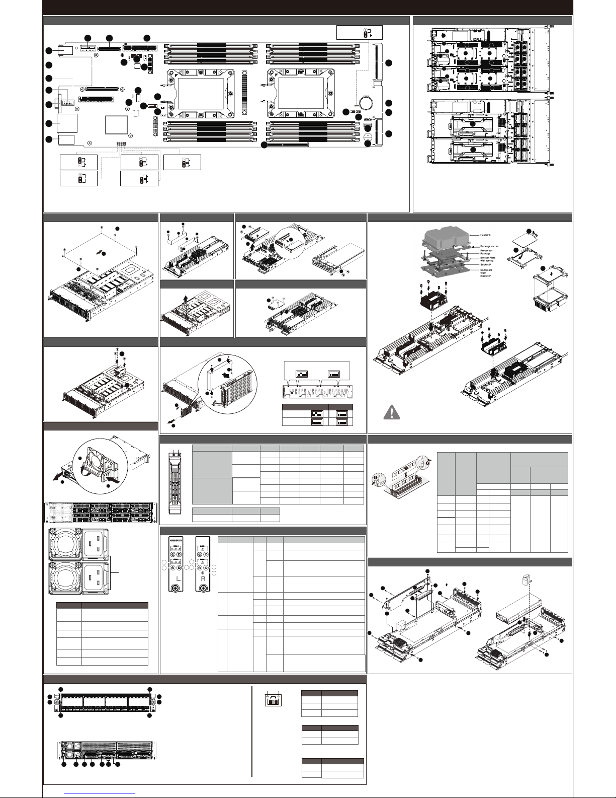
Motherboard Components
21
Clear
CMOS
CLR_CMOS
Enable
Default
1
2
3
1
5
3
6
7
8
9
11
10
12
13
14
18
15
19
20
21
17
16
22
23
24
25
2627
4
2
DIMM_P0_F0
DIMM_P0_E0
DIMM_P0_D0
DIMM_P0_D1
DIMM_P0_A1
DIMM_P0_A0
DIMM_P0_B0
DIMM_P0_C0
DIMM_P1_G1
DIMM_P1_G0
DIMM_P1_H0
DIMM_P1_I0
DIMM_P1_L0
DIMM_P1_K0
DIMM_P1_J0
DIMM_P1_J1
CPU1
(Secondary)
&38
3ULPDU\
BIOS
Recovery
BIOS_RCVR
Default
Enable
1
2
3
Intel ME
Recovery
ME_RCVR
Default
Enable
1
2
3
ME
Force
Update
ME_UPDATE
Default
Enable
1
2
3
Password
Clear
BIOS_PWD
Default
Enable
1
2
3
PMBus
Address Selecon
BIOS_PWD
PCH
BMC
1
2
3
1 USB 3.0 ports
2 OCP 2.0 connector #1
3 PCI Express x8 slot
4 Serial port connector
5 VGA port
6 Gigabit LAN ports
7 Server management LAN port
8 SlimLine SAS connector
9 NSCI Switch
10 SATA 6Gb/s connector (suppport SATA DOM)
11 SATA DOM power connector
12 Intel soware RAID key connector
13 Mezzanine slot #1 (x16 bandwidth)
14 Buzzer
15 SlimLine SAS connector
16 SATA SGPIO connector #1
17 SATA SGPIO connector #2
18 NVMe SSD connector
20 Baery socket
21 NVMe SSD connector
22 PCI Express x8 slot #2
23 IPMB connector
24 TPM connector
25 U.2 connector
26 OCP 2.0 connector #2
27 PCI Express x1 slot #1
CPU/Heat Sink
2
1
3
WARNING!
Please make sure the heat sink installon orientaon for CPU0 and CPU1.
Failure to observe the warning could result in damage to the equipment.
CPU0
CPU1
Power Distribuon Board Cage
1
2
Memory
DIMM
Capacity
(GB)
1 Slot per
Channel
2 Slot per Channel
DIMM Density
Speed (MT/s); Voltage (V)
Slot Per Channel (SPC)
DIMM Per Channel (DPC)
1DPC 1DPC 2DPC
1.2V
2666 2666 2666
1.2V 1.2V
Ranks Per
DIMM and
Data Width
4Gb 8Gb
8GB 8GB
4GB 16GB
8GB 32GB
16GB
N/A 64GB
N/A
N/A
4H 128GB
2H 64GB
N/A 2H 64GB
Type
RDIMM
RDIMM
RDIMM
RDIMM
LRDIMM
LRDIMM
3DS
RDIMM
3DS
QRx4
QRx4
SRx4
SRx8
DRx8
DRx4
QRx4
8Rx4
System Components
1 Power supply unit
2 Riser slot #1
3 OCP slot #3
4 Power supplies
5 CPU0 (Primary)
6 DDR4 Meomery (for CPU0/Primary)
7 CPU1 (Secondary)
8 DDR4 Meomery (for CPU1/Secondary)
1
2
3
4
5
6 8
6 8
7
5
6 8
6 8
9
10
11
12
13
14
15
16
7
2
3
4
9 System fan #1
10 System fan #2
11 System fan #3
12 System fan #4
13 System fan #5
14 System fan #6
15 System fan #7
16 System fan #8
17 GPU Card bay (upper tray)
17
17
Fan Duct
1
1
1
1
2
2
System Fan
PCIe/Riser Card
2
1
3
4
1
2
3
GPU Card
Mezzanine Card
1
1
1
1
1
1
1
3
3
3
3
2
4
4
5
6
7
7
System Cover
Back Cover
1
1
2
1
2
3
4
4
Hard Disk Drive
LED1 LED2
Hard Disk Drive LED
LED 2
HDD Present No HDD
Green
ON
OFF
RAID SKU LED1 Locate Rebuilding
HDD
Fault
HDD
Access
HDD Present
(No Access)
No RAID configuration
(via HBA, ICH)
RAID configuration
(via HW RAID Card or
SW RAID Card)
Disk LED
(LED on
Back Panel)
Green
ON(*1)
OFF
Green
OFF
Removed HDD Slot
(LED on Back Panel)
Disk LED
Removed HDD Slot
ON
OFF
ON(*1)
OFF
OFF
ON
OFF
ON
Alternately
(Low Speed: 2 Hz)
(*3)
(*3)
OFF
OFF
--
--
Green
Amber
Amber
Green
ON(*1)
OFF
Green
--
Green
OFF
OFF
Amber --
Amber
Amber
OFF
OFF
Amber
OFF
Front Panel LEDs and Buons
System is operating normally.
System
Status LED
Green
Amber
Solid On
Critical condition, may indicates:
System fan failure
System temperature
Solid On
Non-critical condition, may indicates:
Redundant power module failure
Temperature and voltage issue
Chassis intrusion
Blink
System is not ready, may indicates:
POST error
NMI error
Processor or terminator missing
N/A
Off
No. Name Color Status Description
1
2
System is powered on.
System is in ACPI S1 state (sleep mode).
System is not powered on or in ACPI S5 state (power off).
System is in ACPI S4 state (hibernate mode).
Power Button
with LED
Green
Green
Solid On
Off
Blink
N/A
System is operating normally.
Green
Amber
Solid On
Critical condition, may indicates:
Power module failure
System fan failure
Power supply voltage issue
System temperature
Solid On
Non-critical condition, may indicates:
Redundant power module failure
Temperature and voltage issue
Chassis intrusion
Blink
3
Unit selected for identification.
No identification.
Blue
N/AOnOff
ID Button
with LED
4
Enclosure
Status LED
HDD Backplane Board SGPIO Configuraon
Supports 6 HDDs Supports 4 HDDs
Intel PCH
LSI/Raid Card
on
off
on
off
Supports 6 HDDs Supports 4 HDDs
2
4
1
3
2
1
3
Power Supply
1
2
3
Secondary PSU
Primary PSU
Power Supply LED
State Description
+12V output ON and OK
No AC power to all power supplies
0.5Hz Blink/Green
2Hz Blink/Green
0.5Hz Blink/Amber
AC presents/Only +12VSB on (PS Off) Or PSU in
Smart standby mode
Amber
Green On
Off
AC cord unplugged, or AC power lost; with a second
power supply in parallel still with AC input power.
Amber
Power supply critical event causing a shutdown;
OTP, OCP, UVP, OVP, fan fail
Power supply firware updating
Power supply warning events where the
power supply continues to operate;
high power current, slow fan
Front & Rear
Power buon/LED:
Green On
Off
Description
System is powered on
System is powered off
State
ID buon/LED:
BlueOn
Off
Description
Unit selected for identification
No identification
State
Speed LED Link/Acvity
LED
Off
State Description
Yellow On 1Gbps data rate
Green On 100Mbps data rate
10Mbps data rate
10/100/1000 LAN LED:
System Fron View
Node 1
Node 2
Node 3
Node 4
2
1
3
3
2
1
3
3
No Descripon
1 Node System Status LED
2 Power buon with LED
3 ID buon with LED
No Descripon
1 Chassis Management Console port
2 Power supply module cord socket
3 USB 3.0 ports
4 VGA port
5 GbE LAN port
6 10/100/1000 Server management LAN port
System Rear View
21 3 4 5 6 7
 Loading...