

Gigabyte GZ-FSCA1-SN, GZ-FSCA1-AN User Manual

3D AURORA
GZ-FSCA1-AN
GZ-FSCA1-SN
User's Manual
20050608-GZFSCA1AN
rev.1003
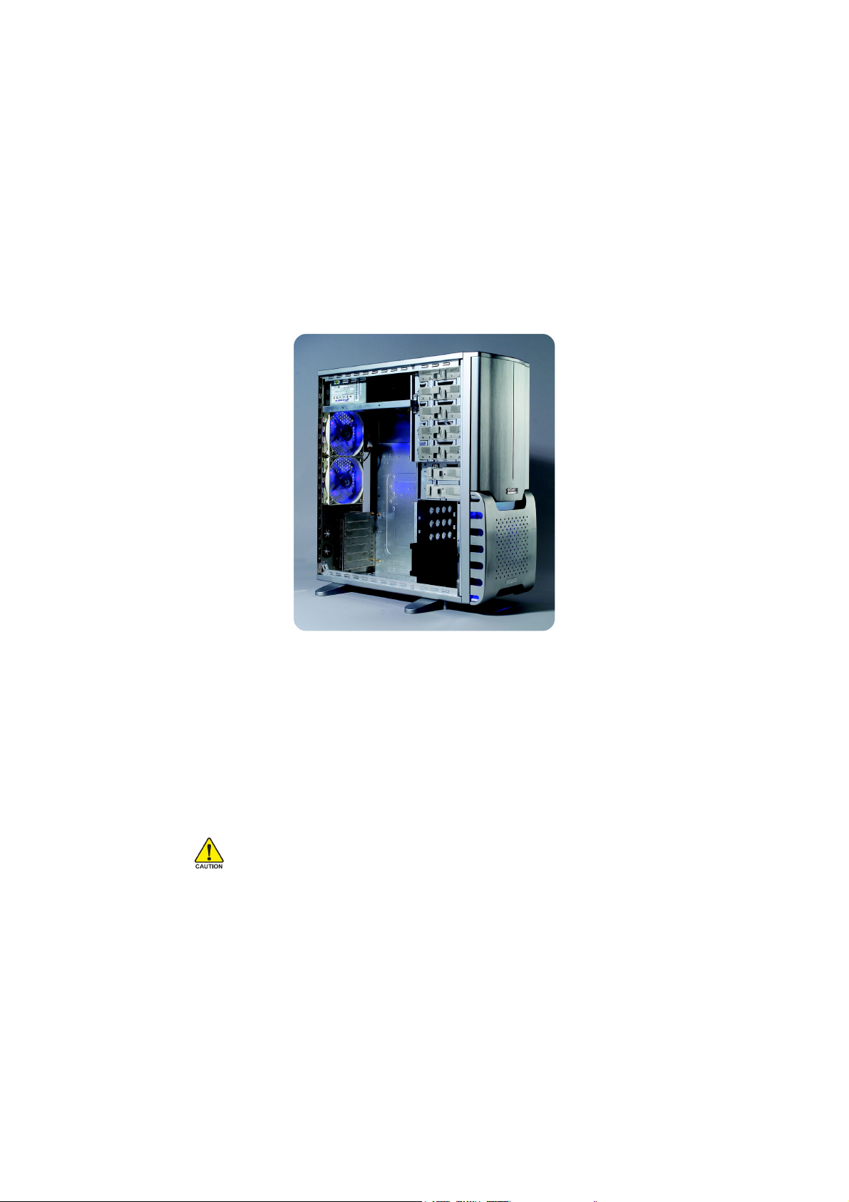
3D AURORA Introduction
Gigabyte Technology has been dedicated to the integration of casing and water/air cooling
technology to provide users with the most optimal solution for thermal dissipation. The five features
of the 3D AURORA series casing include state-of-art design, cooling technology, liquid cooling
support, system security, and easy installation etc. For further information and specifications of the
3D AURORA series, please download them from Gigabyte’s website.
The following are not covered by the warranty:
1. Use the product incorrectly or in a manner other than the designed purpose.
2. Nonobservance of the proper operation provided. (e.g. over-clocking)
3. Malfunction due to interference from other devices.
4. Unapproved modification of the product.
5. Consequential damage to other objects due to the product’s fault.
6. Malfunction arising from casualties (earthquake, thunder, fire, and flood).
7. The product’s warranty label has been removed or damaged.
8. The devices inside, including power supply, hard disk, CD-ROM drive, motherboard, ventilator,
etc, are not detached from the casing prior to the transportation of the computer product,
resulting in damage to the casing or computer-related devices.
9. Any lose due caused by failure to follow the installation process contained in the user.
Caution
Failure to wear gloves during installation of computer products may cause damage to personnel
and devices. Incorrect connector installation may possibly burn out the motherboard and other
components. Be sure to observe the instructions on installation in the manual.
Please refer to the English version for all pictures.

Content
1 Components Introduction ............................................................................................4
1-1 Casing’s Internal Structure....................................................................... 4
1-2 Front, Rear, and Left Side Panel Structure.............................................. 6
2 Features ......................................................................................................................7
3 Specification Features .................................................................................................8
4 Installation Instruction..................................................................................................9
4-1 Installation of Power Supply..................................................................... 9
4-2 Installation of Motherboard ...................................................................... 9
4-3 Installation of Interface Card .................................................................. 10
4-4 Installation of Front I/O Panel .................................................................11
4-5 Casing’s Internal Structure..................................................................... 12
4-6 Installation of 5.25” Front Device Bay .................................................... 13
4-7 Installation of 3.5” Front Device Bay ...................................................... 13
4-8 Installation of Built-in HDD (Hard Disc Drive) ........................................ 14
4-9 DIY Front Bracket of Projector Light ...................................................... 15
4-10 Application of Security Lock................................................................... 16
4-11 Application of Foot Supports.................................................................. 16
4-12 Liquid cooling System Support .............................................................. 17
4-13 Recommended Air Cooling/ Liquid Cooling ........................................... 17
English
1 Components Introduction
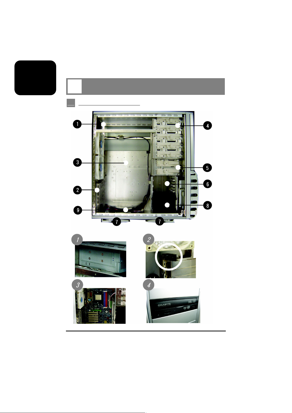
1-1 Casing’s Internal Structure
Power supply
Motherboard/panel card
4
PCI tool-free fastener
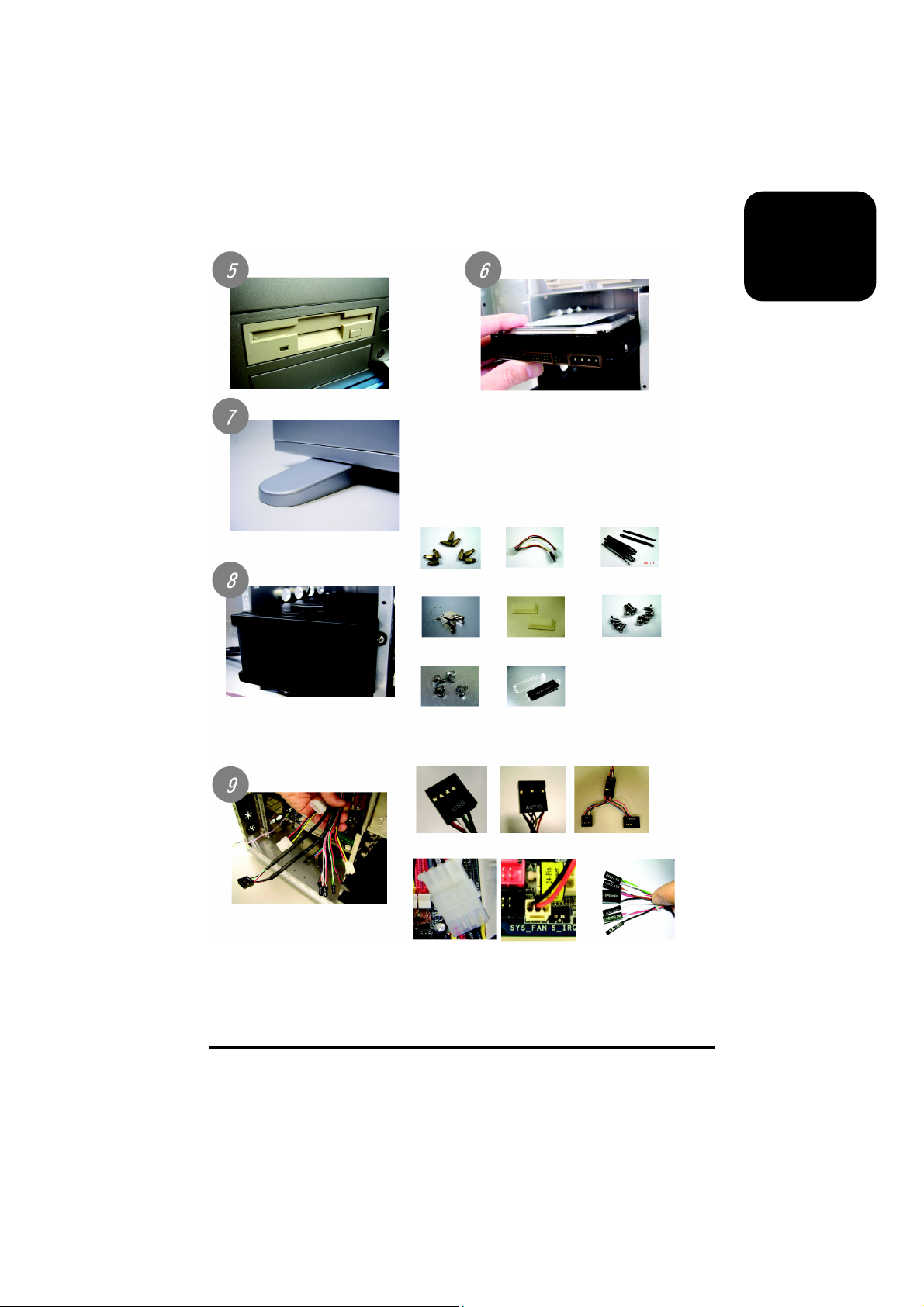
5.25” Front device bay
English
3.5” Floppy
Foot support
Tool enclosure
a. Standoff x 9
d. Key x 2
Built-in hard disk
b. Power extension
cable x 2
e. Wire clamp x 2
c. Securing runner x 10
f. Motherboard
securing screw x 9
(Refer to the right figures for the
attachments in the tool
enclosure)
Front cable kit
(Refer to the right figures for
the cable connectors)
g. Power supply
securing screw x 4
a. USB 2.0 b. AUDIO
d. Front fan power
supply
h. DIY transparent projector panel x 1
(Equipped with 3D AURORA at
shipment)
e. Rear fan power
supply
c. IEEE 1394
f. Basic casing
power switch
control cable kit
5
English
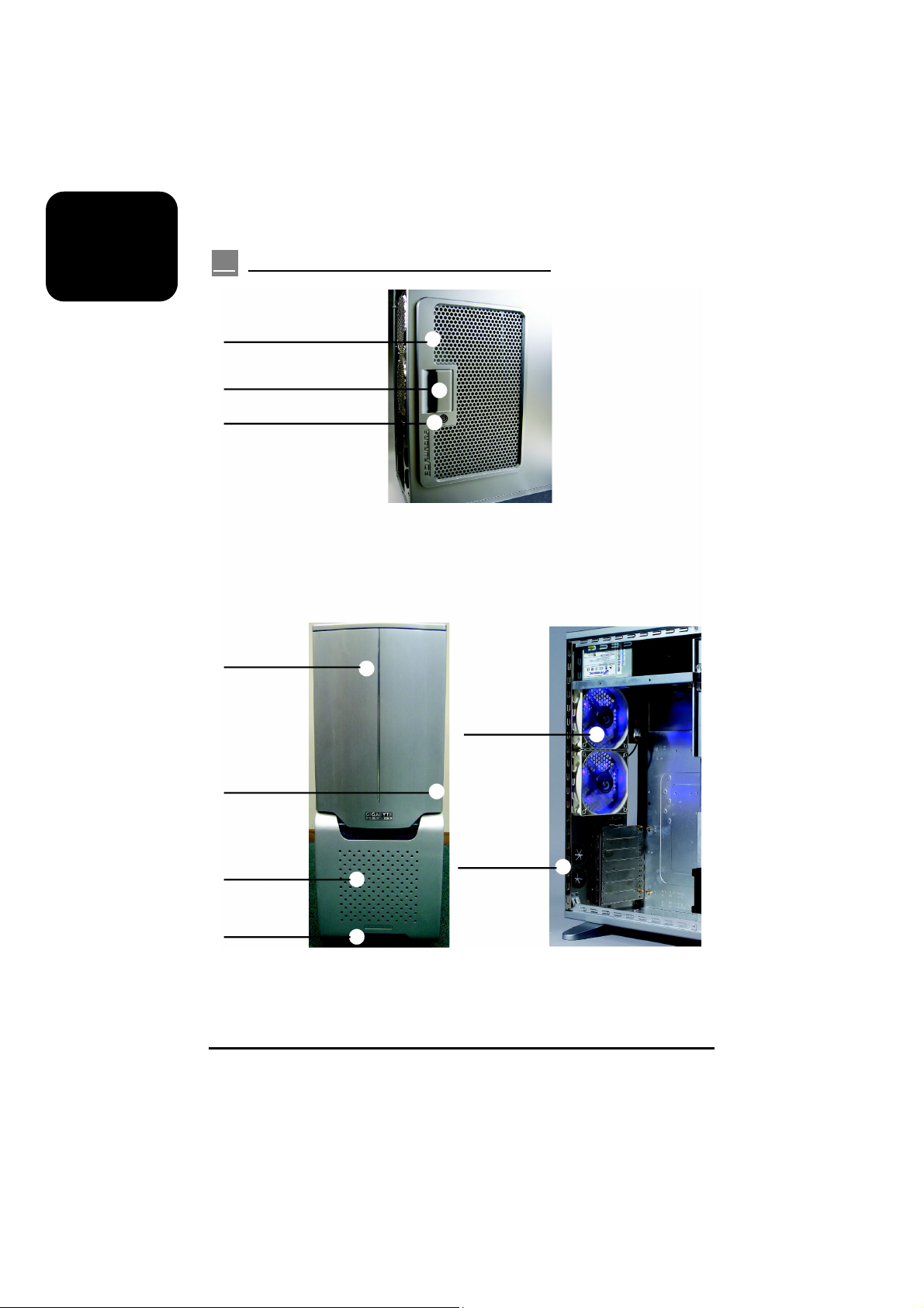
1-2 Front, Rear, and Left Side Panel Structure
Left side panel (A-1)
Latch (A-2)
Side panel security lock (A-3)
Left side panel (A)
Front panel (B-1)
Front panel security lock (B-2)
Front fan (B-3)
Front projector light (B-4)
6
Front panel (B)
Rear dual fan (C-1)
Drainage outlet (C-2)
Rear Panel (C)
 Loading...