

Page 1

3D AURORA
GZ-FSCA1-AN
GZ-FSCA1-SN
User's Manual
20050608-GZFSCA1AN
rev.1003
Page 2
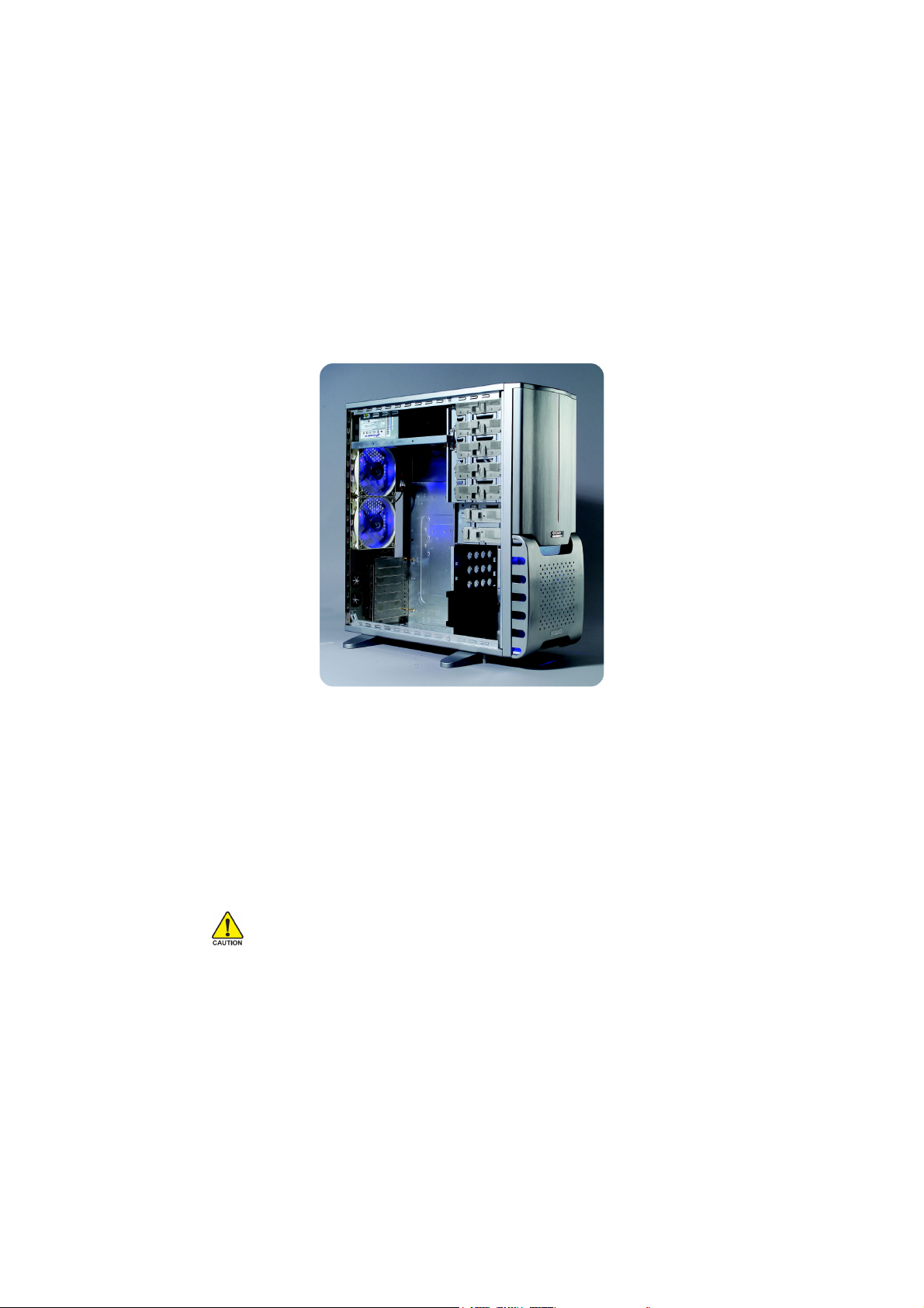
3D AURORA Introduction
Gigabyte Technology has been dedicated to the integration of casing and water/air cooling
technology to provide users with the most optimal solution for thermal dissipation. The five features
of the 3D AURORA series casing include state-of-art design, cooling technology, liquid cooling
support, system security, and easy installation etc. For further information and specifications of the
3D AURORA series, please download them from Gigabyte’s website.
The following are not covered by the warranty:
1. Use the product incorrectly or in a manner other than the designed purpose.
2. Nonobservance of the proper operation provided. (e.g. over-clocking)
3. Malfunction due to interference from other devices.
4. Unapproved modification of the product.
5. Consequential damage to other objects due to the product’s fault.
6. Malfunction arising from casualties (earthquake, thunder, fire, and flood).
7. The product’s warranty label has been removed or damaged.
8. The devices inside, including power supply, hard disk, CD-ROM drive, motherboard, ventilator,
etc, are not detached from the casing prior to the transportation of the computer product,
resulting in damage to the casing or computer-related devices.
9. Any lose due caused by failure to follow the installation process contained in the user.
Caution
Failure to wear gloves during installation of computer products may cause damage to personnel
and devices. Incorrect connector installation may possibly burn out the motherboard and other
components. Be sure to observe the instructions on installation in the manual.
Please refer to the English version for all pictures.
Page 3

Content
1 Components Introduction ............................................................................................4
1-1 Casing’s Internal Structure....................................................................... 4
1-2 Front, Rear, and Left Side Panel Structure.............................................. 6
2 Features ......................................................................................................................7
3 Specification Features .................................................................................................8
4 Installation Instruction..................................................................................................9
4-1 Installation of Power Supply..................................................................... 9
4-2 Installation of Motherboard ...................................................................... 9
4-3 Installation of Interface Card .................................................................. 10
4-4 Installation of Front I/O Panel .................................................................11
4-5 Casing’s Internal Structure..................................................................... 12
4-6 Installation of 5.25” Front Device Bay .................................................... 13
4-7 Installation of 3.5” Front Device Bay ...................................................... 13
4-8 Installation of Built-in HDD (Hard Disc Drive) ........................................ 14
4-9 DIY Front Bracket of Projector Light ...................................................... 15
4-10 Application of Security Lock................................................................... 16
4-11 Application of Foot Supports.................................................................. 16
4-12 Liquid cooling System Support .............................................................. 17
4-13 Recommended Air Cooling/ Liquid Cooling ........................................... 17
Page 4
English
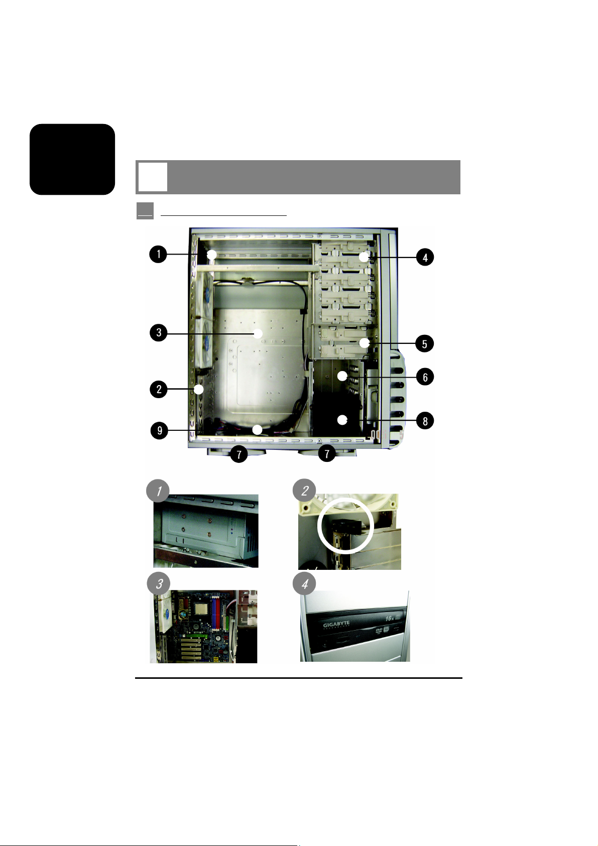
1 Components Introduction
1-1 Casing’s Internal Structure
Power supply
Motherboard/panel card
4
PCI tool-free fastener
5.25” Front device bay
Page 5
English
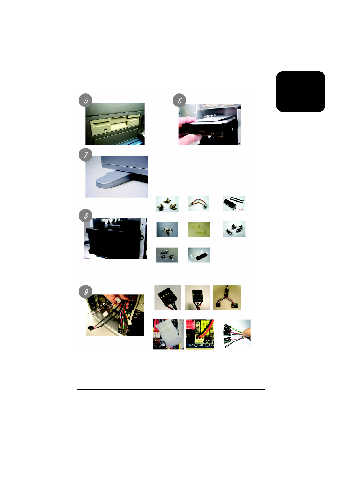
3.5” Floppy
Foot support
Tool enclosure
a. Standoff x 9
d. Key x 2
Built-in hard disk
b. Power extension
cable x 2
e. Wire clamp x 2
c. Securing runner x 10
f. Motherboard
securing screw x 9
(Refer to the right figures for the
attachments in the tool
enclosure)
Front cable kit
(Refer to the right figures for
the cable connectors)
g. Power supply
securing screw x 4
a. USB 2.0 b. AUDIO
d. Front fan power
supply
h. DIY transparent projector panel x 1
(Equipped with 3D AURORA at
shipment)
e. Rear fan power
supply
c. IEEE 1394
f. Basic casing
power switch
control cable kit
5
Page 6
English
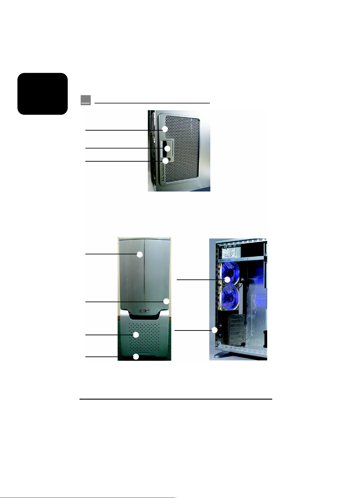
1-2 Front, Rear, and Left Side Panel Structure
Left side panel (A-1)
Latch (A-2)
Side panel security lock (A-3)
Left side panel (A)
Front panel (B-1)
Front panel security lock (B-2)
Front fan (B-3)
Front projector light (B-4)
6
Front panel (B)
Rear dual fan (C-1)
Drainage outlet (C-2)
Rear Panel (C)
Page 7

2 Features
- High quality design -
Gigabyte top-class full tower cooling casing.
Lightweight aluminum casing (GZ-FSCA1-AN only)
Full-open aluminum panel design, top-class hairline finish
Personalized ‘Gigabyte LOGO projector display (patent pending)
- Complete support -
Complete front multimedia support, including 2 USB 2.0 ports / 1 IEEE 1394 /1 audio line-out
and mic-in jacks.
Liquid cooling system full support:
including large-sized drainage inlet/outlet, pump securing hole, and cooling kit securing hole
Supporting ATX/Micro AT/Mini AT/Flex ATX motherboard.
- Integration of cooling technology -
Full aluminum casing (GZ-FSCA1-AN only) for accelerating system-cooling performance.
A set of front 12 cm blue LCD cooling fans with multi-way intake panel that allows air coming in
from three directions (front, let and right).
Industry leading two sets of rear 12 cm blue LCD silent cooling fans, large air volume but low
noise.
Unique intake side panel design.
Dust-proof design of front/side panel air intake.
- System security -
Double security lock design, front/side panel, providing optimism system security.
Reinforced nickel-plated rear panel.
1.0mm reinforced aluminum / zinc plated steel panel design.
- Convenience of assembly -
Scratch-resistant processing that ensures safety during assembly.
Tool-free installation design.
Detachable tool enclosure where tools, screws and cables can be stored.
Single-hand side panel open device, easy for disassembly.
English
7
Page 8

English
3 Specification Features
Model : GZ-FSCA1-AN / GZ-FSCA1-SN
Case Type : Full Tower
Dimensions : 205 x 522 x 510 (W x H x D)
Front bezel Material : Aluminum
Colour : Silver / Black
Side Panel : Elegant design
Body Material : Aluminum (1.0mm) GZ-FSCA1-AN / SECC (1.0mm)
GZ-FSCA1-SN
Net Weight : 7.1 kg /11.7 kg
5.25” drive bay (External) : 5
3.5” drive bay (External) : 2
3.5” drive bay (Internal) : 5
PCI port : 7
Compatible Motherboard : ATX / Micro ATX / Mini ATX / Flex ATX
System Fan (front) : One 12 cm silent fan equipped with blue LEDs (1000 rpm)
System Fan (rear) : Two 12 cm silent fans equipped with blue LEDs (1000 rpm)
I / O Ports (front) : 2 USB2.0 / One IEEE 1394 / 1 audio line-out and mic-in jacks
Optional Thermal Solutions :
GIGABYTE Liquid Cooling - 3D Galaxy Series
GIGABYTE Air Cooling - G-Power Series
- 3D Rocket Series
8
Page 9

4 Installation Instruction
Please follow the reference sections in order for installation.
4-1 Installation of Power Supply
To facilitate the installation, it is recommended to place the 3D AURORA casing upright on the
table.
Required tools: power supply securing screws x 4.
4-1-1 Remove the side panel.
Unscrew the thumbscrews of the side panel and
detach the panel by pressing the latch.
English
4-1-2 Place the power supply into the casing.
4-1-3 Use screws to secure the power supply from the rear
side.
cross bar
4-1-4 For a larger power supply, please loosen the cross
bar screws first, disassemble the bar, and then install
the power supply; fasten the screws to secure the
cross bar after installation.
4-2 Installation of Motherboard
The 3D AURORA is compatible with the ATX/Micro ATX/Mini ATX/Flex ATX motherboard. Please
confirm the dimension and specifications of the motherboard before installation.
Required tool: motherboard standoffs x 9 and securing screws x 9
9
Page 10

English
4-2-1 According to motherboard specifications, select
proper screw holes, engage the standoffs into the
corresponding holes of the casing.
4-2-2 Secure the motherboard with securing screws.
Motherboard Code Securing screw Standoffs
ATX A1-A9 9 9
MINI ATX M1-M9 9 9
MICRO ATX U1-U9 9 9
FLEX ATX F1-F6 6 6
Select proper “rear I/O panel” of the motherboard (typically supplied by motherboard
manufactures).
4-3 Installation of Interface Card
The 3D AURORA supports tool-free installation of interface cards, e.g. Graphic card and Network
Card, etc.
Required tool: None
4-3-1 Open the PCI slot retention lock.
10
4-3-2 Remove the internally attached dust-proof PCI cover.
4-3-3 Insert the interface card into the expansion slot with
care.
Make sure all interface cards are fully seated in the
corresponding slots.
Page 11

4-4 Installation of Front I/O Panel
Incorrect connector installation may possibly burn out the motherboard and other
components. Be sure to observe the instructions on installation in the manual. Any loss
arising from nonobservance of the proper operation provided is not covered by the
warranty.
Different motherboards may have different installation positions. For detailed
instructions, please refer to the instructions supplied by the motherboard manufacturer.
The front panel consists of (1) 2 USB 2.0 / 1 IEEE 1394 / 1 audio line-out jack; and
(2) a basic casing power switch control cable kit
Required tool: None
(1) 2 USB 2.0 / 1 IEEE 1394 / 1 Audio line-out jack
4-4-1 Insert the USB 2.0 connectors into the corresponding sockets on the motherboard.
USB 2.0 Connector
4-4-2 Insert the IEEE 1394 connector into the corresponding socket on the motherboard.
Please refer to the instructions supplied by the motherboard manufacturer and make sure
the correct type of connector prior to installation.
a. IEEE1394 Connector A
b. IEEE1394 Connector B
c. IEEE1394 Connector C
Pin Definition Pin Definition
1 Power 6 USB Dy+
2 Power 7 GND
3 USB Dx- 8 GND
4 USB Dy- 9
5 USB Dx+ 10 USB Over Current
Pin Definition Pin Definition
1 TPA+ 6 TPB2 TPA- 7
3 GND 8 +12V
4 GND 9 +12V
5 TPB+ 10 GND
Pin Definition Pin Definition
1 TPA+ 6 TPB2 TPA- 7 +12V
3 GND 8 +12V
4 GND 9
5 TPB+ 10 GND
Pin Definition Pin Definition
1 +12V 9 +12V
2 +12V 10 +12V
3 TPA+ 11 TPA1+
4 TPA- 12 TPA15 GND 13 GND
6 GND 14
7 TPB+ 15 TPB1+
8 TPB- 16 TPB1-
English
11
Page 12

English
4-4-3 Insert the Audio connector into the corresponding socket on the motherboard.
Pin Definition Pin Definition
1 MIC 6 Rear Audio (R)
2 GND 7 Reserved
3 REF 8
4 POWER 9 Front Audio (L)
5 Front Audio (R) 10 Rear Audio (L)
(2) Basic casing power switch control cable kit.
Follow the connectors listed below for installation (see the figure below).
Connector Color
Speaker Red(+) / Black(-)
Reset SW Green(+) / White(-)
Power SW Red(+) / White(-)
POW LED+ Black
POW LED- White
H.D.D. LED Brown(+) / White(-)
Be sure to remember that different motherboards may have different installation
positions. For detailed instructions, please refer to the instructions supplied by the
motherboard manufacturer.
4-5 Casing’s Internal Structure
The 3D AURORA is equipped with one 12cm silent LED cooling fan at front / two at rear.
Required tool: None
12
4-5-1 Plug the front fan 4-pin power cable into the 4-pin
connector on the motherboard.
4-5-2 Plug the rear fan 3-pin power connector into the fan
power connector of the motherboard system.
Page 13

4-6 Installation of 5.25” Front Device Bay
The installation of 5.25” CD-ROM is also intended for installation of general 5.25” front device bay.
Required tool: None
4-6-1 Open the front panel, remove the 5.25” plastic drive
rail and internal metal panel.
4-6-2 Slide the 5.25” CD-ROM into the drive.
English
4-6-3 Refer to the installation order illustrated in the left
figure and secure the 5.25” CD-ROM by controlling
the latch (reverse steps for disassembly).
4-6-4 Installation completed.
4-7 Installation of 3.5” Front Device Bay
The installation of 3.5” floppy disc drive intended for installation of general 3.5” front device bay
Required tool: None
4-7-1 Same as Step 4-6-1.
4-7-2 Slide the 3.5” floppy disc drive into the drive bay.
13
Page 14

English
4-7-3 Refer to the installation order illustrated in the left
figure and secure the 3.5” floppy disc drive by
controlling the latch. (reverse steps for disassembly)
4-7-4 Installation completed.
4-8 Installation of Built-in HDD (Hard Disc Drive)
The 3D AURORA provides built-in bays to accommodate up to 5 hard disc drives (after removal of
the tool enclosure). The built-in HDD requires securing runners, which can be found in the black
tool enclosure.
Required tool: Securing runners x 10 in the tool enclosure and power extension cables x 2.
4-8-1 Use the runners installed on both sides of the HDD
evenly and slide the HDD into the hard disk drive
bay.
14
4-8-2 For installation of the fourth and fifth HDDs, loosen
the tool enclosure, and then install the HDD in
accordance with Step 4-8-1.
4-8-3 In case the length of power cable is not sufficient for
installation of the bottom HDD, it is possible to use
the power extension cable inside the tool enclosure,
depending on the HDD with 4-pin or SATA power
cable.
Page 15

4-9 DIY Front Bracket of Projector Light
The 3D AURORA is provided with another transparent projector panel, which can be DIY designed
and replaced with the projector bracket under front panel.
Required tool: transparent projector panel (slides and laser printer or copy machine should be
provided by the user)
4-9-1 Visit Gigabyte’s website,
(http://tw.giga-byte.com/Peripherals/Support/
Manual/Manual_List.htm)
and search for the 3D AURORA series; the file name:
DIYbracket.doc
Print out the slides by 1:1 (please use the laser
printer or copy machine).
English
4-9-2 Trim the slide along the edge lines.
4-9-3 Post the trimmed slide onto the transparent projector
panel.
4-9-4 Lay the casing on the table, disassemble the original
projector panel, as shown in Figure a; install the
newly made projector panel onto the casing, as
shown in Figure b.
4-9-5 Installation completed.
15
Page 16

English
4-10 Application of Security Lock
The 3D AURORA is supplied with two security locks, including a panel lock and a side panel lock.
Required tool: key x 2
4-10-1 Insert and turn the key by 90° as shown in the figure,
and lock it.
4-10-2 Insert and turn the key by 90° as shown in the figure,
and unlock it.
4-11 Application of Foot Supports
The 3D AURORA is supplied with four foot supports for ensuring the casing is firmly seated on the
holding surface.
4-11-1 Swivel these four feet by 90° as shown in the figure
to loosen the feet.
16
4-11-2 Swivel these four feet by 90° as shown in the figure
to fasten the feet.
Page 17

4-12 Liquid cooling System Support
The 3D AURORA series casing can fully support the Gigabyte 3D Galaxy liquid cooling kit (also
support most of the liquid cooling systems commercially available). While installing the liquid
cooling system, please consult its manual first.
The liquid cooling system is optional.
4-13 Recommended Air Cooling/ Liquid Cooling
The 3D AURORA is recommended to be used with the Gigabyte Air Cooling series.
English
17
Page 18

English
18
 Loading...