

Gigabyte GZ-FADA51-CJB, Sumo 5112 GZ-FADA51-CJB User Manual

Black
English User’s Manual
Thank you for purchasing a GIGABYTE Chassis. GIGABYTE is
dedicated to the integration of water/air-cooling chassis solutions to
provide users with the most optimal solution for thermal dissipation.
For further information and specifications of the “SUMO” series,
please visit GIGABYTE website. (http://www.gigabyte.com.tw)
The following is not covered by warranty:
1. Using the product incorrectly or in a manner other than its designed purpose.
2. Nonobservance of its proper operation as provided in documentation.
3. Malfunction due to interference from other devices.
4. Unapproved modification of the product.
5. Consequential damage to other object due to the product’s fault.
6. Malfunction arising from natural hazards, e.g. earthquake, lightning, fire, and floods.
7. Warranty void if label has been removed or tampered with.
8. The devices inside, including power supply, hard disk, CD-ROM drive, motherboard, ventilator, etc, are not
detached from the casing prior to transportation of the computer system, resulting in damage to the casing
or other computer-related devices.
9. Any loss/damage caused by failure to follow the installation process with in the user manual.
Failure to wear gloves during installation of computer products may cause bodily harm or damage to your devices. Incorrect connector
installation may possibly burn out the motherboard and other components. Be sure to obser ve the instructions in the installation
manual.
02
English

Content
1. Components Introduction 04
1-1 Casing’s Internal Structure 04
1-2 Casing’s Panel Structure 05
1-3 Removal of Side and Front Panels 05
2. Features 06
3. Specifications 07
4. Installation Instruction 08
4-1 Installation of Power Supply 08
4-2 Installation of Motherboard 08
4-3 Installation of Add-On card 08
4-4 Installation of Front Multi-Media I/O Ports 09
4-5 Connection of Fan Power Cable 10
4-6 Installation of 5.25” Front Device Bay 10
4-7 Installation of 3.5” Front Device Bay 10
4-8 Installation of 3.5” Internal Device Bay 10
4-9 Application of Removable/Dual Directional HDD Rack 11
4-10 Installation of 2.5” Enclosure 11
4-11 Application of DIY inter changeable LED lighting 11
4-12 Application of Security locks 11
4-13 Application of Foot Support 12
4-14 Application of Liquid Cooling System 12
4-15 Recommended GIGABYTE Thermal Solution products 12
03
English
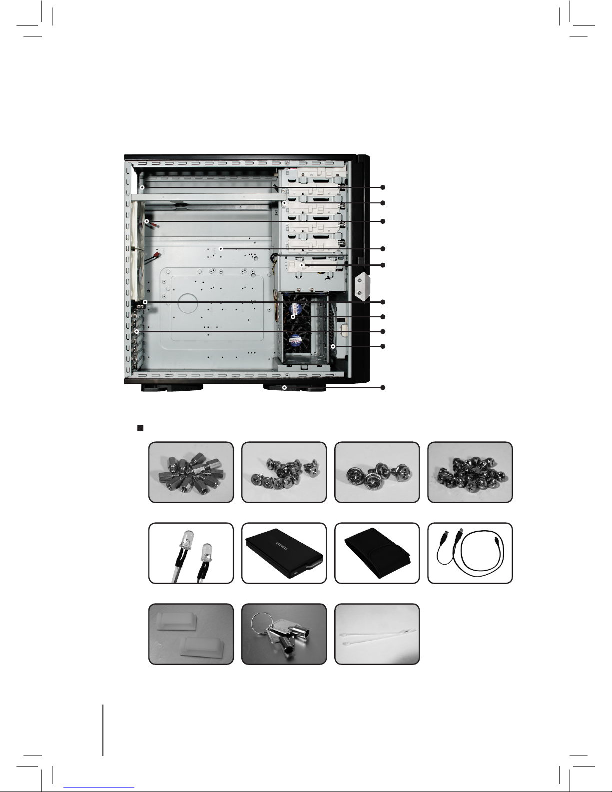
1. Components Introduction
1-1 Casing’s Internal Structure
Accessory Box
(Refer to the figures below for the attachments in the accessory box)
5.25” Front Device Bay
Dual Rear fans
Piping Outlets
PCI Tool-Free Fastener
3.5” Front Device Bay
3.5” Internal Device Bay
Foot Support
Motherboard tray and PCI Slot panel
Front intake Fan
Power Supply Bay
Coppe r Stand Off x 11
3.5” Dev ice Thumbscrews
x 8
Power Sup ply Securing
screw x 4
Motherboard Securing
Screw x 12
Blue Led
USB Y Cableprotec tive car ry bag
2.5” HDD mobile enclosure
Wire Clamp x 2
Key Cable tie x 2
04
English
 Loading...