

Gigabyte GZ-AA1CB-SNS, GZ-AA1CB-SNB, GZ-AA1CB-SNG, GZ-AA2CB-SNS, GZ-AA2CB-SNG User Manual
...
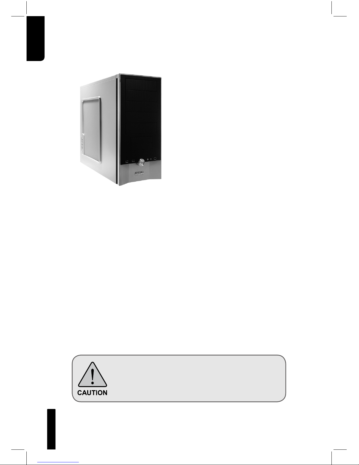
iSolo 210
English User’s Manual
GZ-AA1CB-SNS/SNB/SNG
2
English
Thank you for purchasing GIGABYTE
Tech. thermal product. GIGABYTE
Tech. is dedicated to the integration
of casing water/air-cooling solution
technology to provide users with the
most optimal solution for thermal
dissipation. For further information
and specifications of the “iSolo” series,
please visit GIGABYTE Tech. website.
(http://www.gigabyte.com.tw)
The following are not covered by the warranty:
1. Using the product incorrectly or in a manner other than the designed
purpose.
2. Nonobservance of the proper operation provided
3. Malfunction due to interference from other devices
4. Unapproved modification of the product
5. Consequential damage to other devices due to the product’s fault.
6. Malfunction arising from natural hazards, e.g. earthquake, lightning,
fire, and floods.
7. The product’s warranty label has been removed or damaged.
8. The devices inside, including power supply, hard disk, CD-ROM
drive, motherboard, ventilator, etc, are not detached from the
casing prior to transportation of the computer system, resulting in
damage to the casing or other computer-related devices.
9. Any loss/damage caused by failure to follow the installation process
with in the user manual.
Failure to wear gloves during installation of computer
products may cause bodily harm or damage to your
devices. Incorrect connector installation may possibly
burn out the motherboard and other components. Be
sure to observe the instructions in installation manual.

English
3
Table of Contents
1. Components Introduction 3
1-1 Casing’s Internal Structure 4
1-2 Front, Rear, and Left Side Panel Structure 5
1.3 Removal of Side and Front Panel 5
2. Features 6
3. Specifications 7
4. Installation Instruction 8
4-1 Installation of Power Supply 8
4-2 Installation of Motherboard 8
4-3 Installation of Add-on Card 9
4-4 Installation of Front Multi-Media I/O port 10
4-5 Connection of Fan Power Cables 11
4-6 Installation of 5.25” Front Device Bay 11
4-7 Installation of 3.5” Front Device Bay 12
4-8 Installation of 3.5” Internal Device Bay 12
4-9 Foot Supports 13
4-10 Liquid Cooling System Support 13
4-11 Recommended Cooling Products 14
4
English
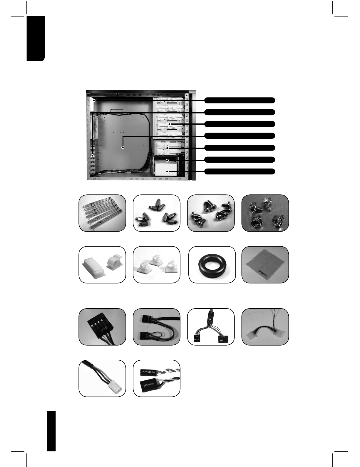
1.Components Introduction
1-1 Casing’s Internal Structure
Accessory Box
Front Cable Kit
Power Supply
Securing Screw x 4
Dust Remover
Cloth
USB 2.0 Audio Set
(HD & AC’97)
IEEE1394
(Multi-connectors)
Front Light 4-Pin
Power Connector
3-Pin Fan Connector Power SW/Speaker
Connector
Power Supply Bay
PCI Tool-Free Fastener
Motherboard tray
5.25” Front Device Bay
3.5” Internal Device Bay
Accessory Box
(Refer to the figures below for the attachments in the accessory box)
(Refer to the figures below for the cable connectors)
Copper Stand Off
x 9
Securing Runner x 6 Motherboard
Securing Screw x 9
Large Wire Clamp
x 2
Magnet Ring x 1Mini Wire Clamp
x 3
3.5” Front Device Bay
English
5
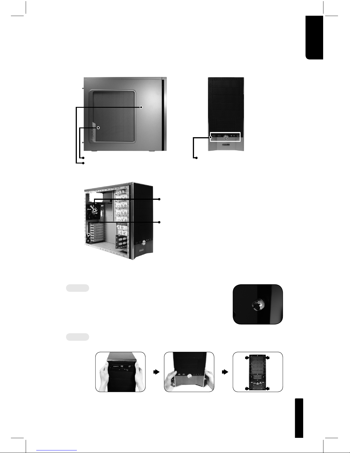
1-2 Front, Rear, and Left Side Panel Structure
a) Left Side Panel
b) Front Panel
c) Rear Panel
1-3 Removal of Side and Front Panels
1-3.1 To remove side panels:
1-3.1a Remove the 4 thumb screws at the rear of
the side panel, and detach the side panels.
1-3.2 To remove front panel:
1-3.2a Remove the left and right side panels, release the 4
clamps that hold the front panel onto the chassis.
Ventilated Mesh Side Panel Kit
Left Side Panel
Rear Fan
Power Switch and Front
Multi-Media I/O port
LCS Tube Outlets
 Loading...