

Gigabyte GV-N570OC-13I Rev 2.0, GV-N570UD-13I User Manual

GV -N570OC-13I Rev 2.0/
GV-N570OC-13I/
GV-N570UD-13I
NVIDIA® GeForceTM GTX 570 Graphics Accelerator
User's Manual
Rev. 102
12MM-N570OC-102AR
Copyright
© 2011 GIGABYTE TECHNOLOGY CO., L TD
Copyright by GIGA-BYTE TECHNOLOGY CO., LTD. ("GBT"). No part of this manual may be reproduced or transmitted
in any form without the expressed, written permission of GBT.
Trademarks
Third-party brands and names are the properties of their respective owners.
Notice
Please do not remove any labels on this graphics card. Doing so may void the warranty of this card.
Due to rapid change in technology, some of the specifications might be out of date before publication of this this manual.
The author assumes no responsibility for any errors or omissions that may appear in this document nor does the author
make a commitment to update the information contained herein.
Rovi Product Notice:
This product incorporates copyright protection technology that is protected by U.S. patents and other intellectual property rights.
Use of this copyright protection technology must be authorized by Rovi Corporation, and is intended for home and other limited
viewing uses only unless otherwise authorized by Rovi Corporation. Reverse engineering or disassembly is prohibited.
VGA Card
GV-N570OC-13I
Jan. 14, 2011
VGA Card
GV-N570OC-13I
Jan. 14, 2011
VGA Card
GV-N570UD-13I
Apr. 18, 2011
VGA Card
GV-N570UD-13I
Apr. 18, 2011

- 4 -GV-N500 Series Graphics Accelerator
Table of Contents
1. Introduction ................................................................................................................ 5
1.1. Features ......................................................................................................................... 5
1.2. Minimum System Requirements .................................................................................... 5
2. Hardware Installation.................................................................................................. 6
2.1. Board Layout ................................................................................................................. 6
2.2. Hardware Installation.................................................................................................... 10
3. Software Installation.................................................................................................. 12
3.1. Driver and Utility Installation......................................................................................... 12
3.1.1. Driver Installation ......................................................................................................... 12
3.2. Display Properties Pages ........................................................................................ 14
3.3. Accessing NVIDIA Control Panel............................................................................ 15
4. Troubleshooting Tips................................................................................................ 23
5. Appendix ................................................................................................................. 24
5.1. How to Reflash the BIOS in MS-DOS Mode.............................................................. 24
5.2. Resolutions and Color Depth Table (In Windows XP)................................................... 25
5.3. Regulatory Statements ................................................................................................. 27

- 5 - Introduction
1. Introduction
1.1. Features
• Powered by NVIDIA® GeForceTM GTX 570 Graphics Processing Unit (GPU)
• Supports PCI Express 2.0
• Integrated with 1280 MB GDDR5 memory
• Supports DirectX
®
11
• Supports NVIDIA
®
SLI
TM
(Scalable Link Interface) technology
(Note 1)
• Supports 2 Dual-Link DVI-I connectors and 1mini HDMI connector
(GV-N570UD-13I /GV-N570OC-13I)
• Supports 2 DVI connectors,one HDMI connector and one Displayport connector
(GV-N570OC-13I Rev2.0)
• Supports HDCP (High-Bandwidth Digital Content Protection) technology
1.2. Minimum System Requirements
• Hardware
- 600-watt system power supply specification or above is recommended
- Intel® Pentium® 4 or AMD AthlonTM XP class
- 2GB system memory (4GB recommended)
- Optical drive for software installation (CD-ROM or DVD-ROM drive)
• Operating System
- Windows
®
7
- Windows
®
Vista
- Windows
®
XP
• SLI
TM
Configuration
If you are planning on using this graphics card as part of an SLI system, the following
are required:
- An SLI certified motherboard with two/three PCIe x16 slots and correct chipset driver
- T wo GV-N570OC-13I / GV -N570OC-13I Rev 2.0 / GV-N570UD-13I for SLI configuration;
Three GV-N570OC-13I / GV-N570OC-13I Rev 2.0 / GV-N570UD-13I
for 3-way SLI configuration
- A power supply with 900-watt or above is recommended
- An SLI bridge connector or 3-way SLI bridge connector
(Note 1) SLI technology requires a PCI Express motherboard with two/three x16 physical connectors.
Graphics cards working in an SLI configuration must be with the same model name
(e.g.GV-N570OC-13I / GV-N570OC-13I Rev 2.0 /GV-N570UD-13I) and from the same vendor
(e.g. GIGABYTE TECHNOLOGY).
- 6 -GV-N500 Series Graphics Accelerator
2. Hardware Installation
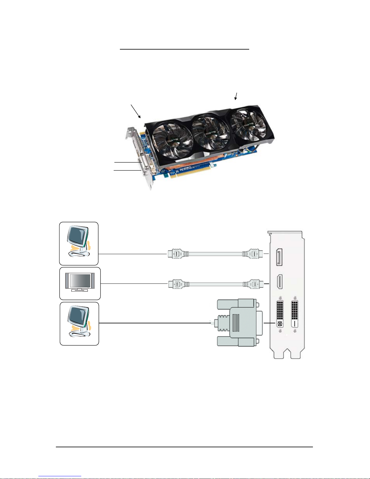
2.1. Board Layout
DVI
Connector
Digital LCD Monitor
SLI Connector
DVI-D connector 1
DVI-I Connector 2
Power Connectors
HDMI Connector
DisplayPort Connector
1.GV-N570OC-13I Rev 2.0
DisplayPort
Connector
HDMI
Connector
DVI Output
HDMI TV
Digital LCD Monitor
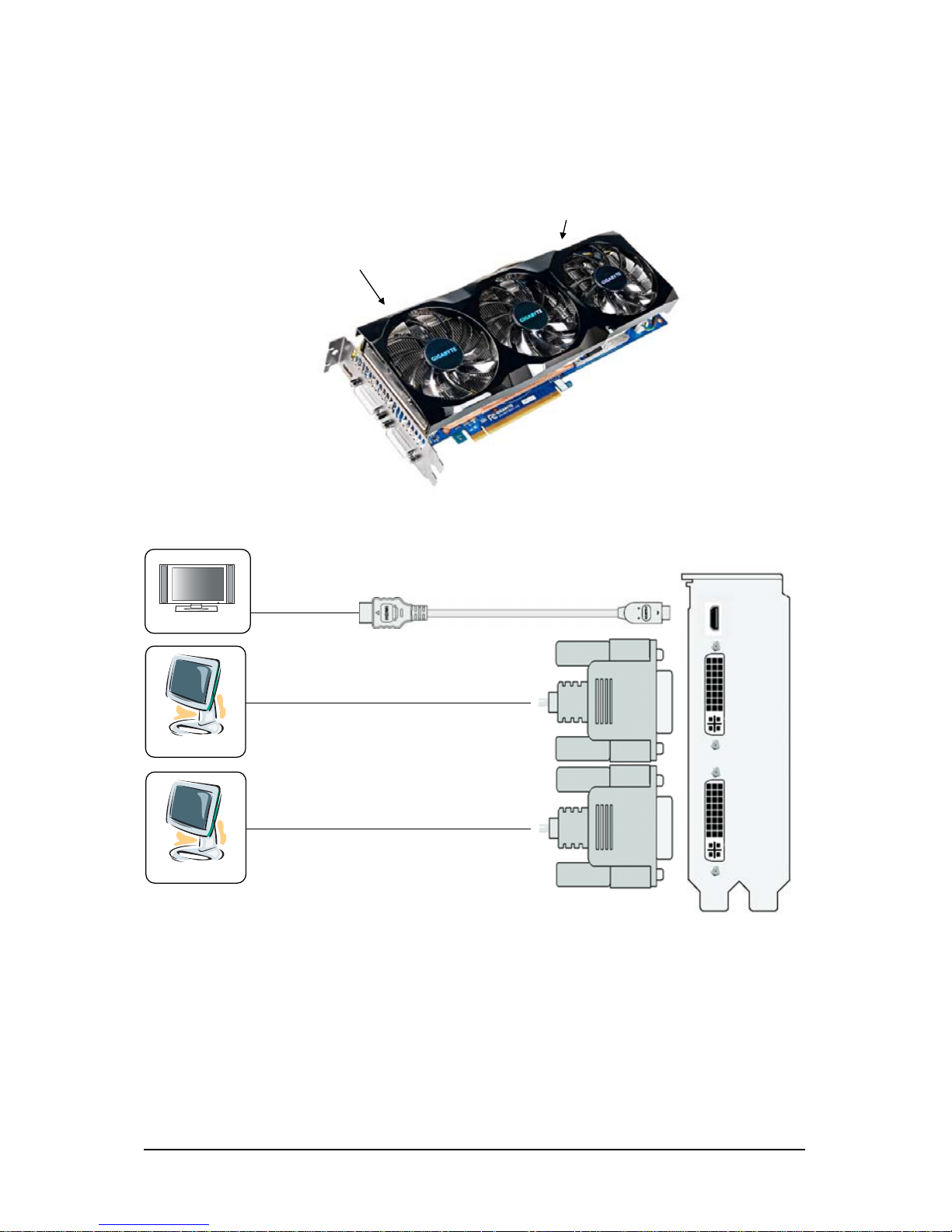
- 7 - Hardware Installation
Mini HDMI
Connector
DVI-I
Connector 1
DVI-I
Connector 2
Digital LCD Monitor
DVI Output
HDMI TV
Digital LCD Monitor
DVI Output
Mini HDMI to HDMI cable(optional)
SLI Connector
Mini HDMI Connector
DVI-I Connector 1
DVI-I Connector 2
Power Connectors
2.GV-N570OC-13I / GV-N570UD-13I
- 8 -GV-N500 Series Graphics Accelerator
The GV-N570OC-13I / GV-N570OC-13I Rev 2.0 / GV-N570UD-13I graphics card is a performance
optimized high-end card. Power is taken from the PCI Express host bus as well as the external PCI
Express power connectors.
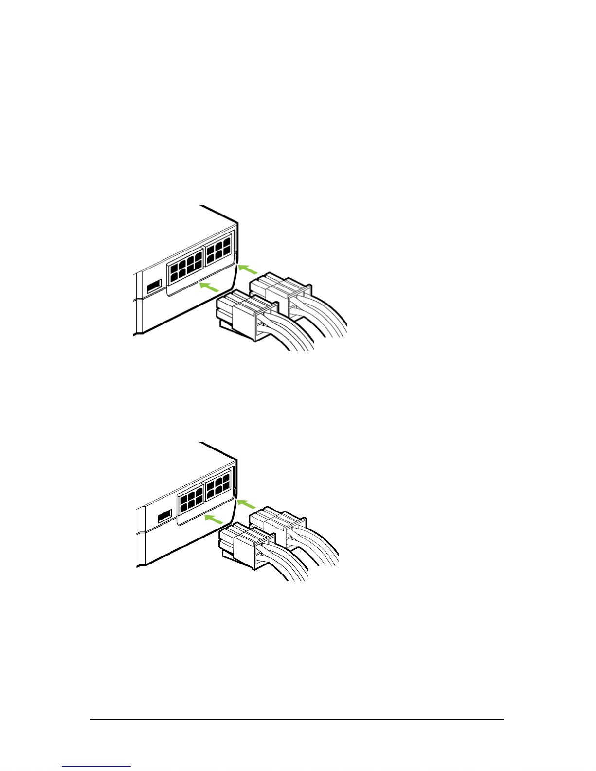
NVIDIA power
Connect power from the system power supply to the GeForce card(s).Use the connection method for
your particular graphics card.
• GV-N570OC-13I / GV-N570UD-13I:
Connect BOTH a 6-pin AND an 8-pin PCI Express auxiliary power connector coming from the
computer power supply to the connectors on the top edge of the GeForce GTX 570 graphics
card.
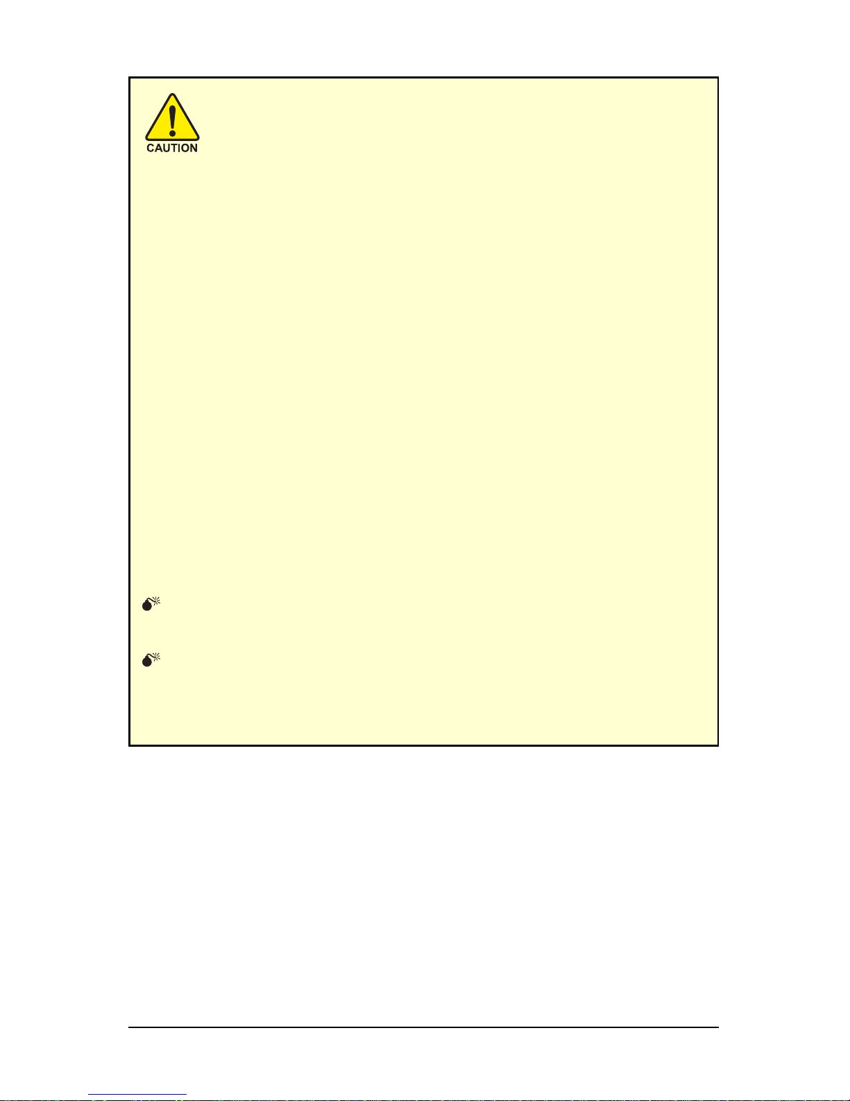
• GV-N570OC-13I Rev 2.0:
Connect two 6-pin PCI Express auxiliary power connectors coming from the computer
power supply to the connectors on the top edge of the GeForce GTX 570 graphics card.
- 9 - Hardware Installation
Expansion cards contain very delicate Integrated Circuit (IC) chips. To
protect them against damage from static electricity, you should follow some
precautions whenever you work on your computer.
1. Turn off your computer and unplug power supply.
2. Use a grounded wrist strap before handling computer components. If you do not
have one, touch both of your hands to a safely grounded object or to a metal object,
such as the power supply case.
3. Place components on a grounded antistatic pad or on the bag that came with the
components whenever the components are separated from the system.
The card contains sensitive electric components, which can be easily damaged by static
electricity, so the card should be left in its original packing until it is installed.
Unpacking and installation should be done on a grounded anti-static mat. The operator
should be wearing an anti-static wristband, grounded at the same point as the anti-static
mat.
Inspect the card carton for obvious damage. Shipping and handling may cause damage
to your card. Be sure there are no shipping and handling damages on the card before
proceeding.
DO NOT APPLY POWER TO YOUR SYSTEM IF THE GRAPHICS CARD IS
DAMAGED.
In order to ensure that your graphics card can work correctly, please use
official GIGABYTE BIOS only. Using non-official GIGABYTE BIOS might
cause problem(s) on the graphics card.
 Loading...