

GIGABYTE GS-R22T61, GS-R22T81 Owner's Manual

GIGABYTE
GS-R22T61-RH/GS-R22T81-RH
2U Rack Mount Server
Service Guide
Dual Intel® Xeon LGA1366 Processor Serverboard
Rev. 1.0

Preface
Before using this information and the product it supports, please read the following general information.
1. This Service Guide provides you with all technical information relating to the BASIC
CONFIGURATION decided for GIGABYTE's “global” product of fering. To better fit local market
requirements and enhance product competitiveness, your regional office MA Y have decided to
extend the functionality of a machine (e.g. add-on card, modem, or extra memory capability).
These LOCALIZED FEATURES will NOT be covered in this generic service guide. In such
cases, please contact your regional offices or the responsible personnel/channel to
provide you with further technical details.
2. Please note WHEN ORDERING FRU P ARTS, you should check the most up-to-date information
available on your regional web or channel. For whatever reason, if a part number change is made,
it will not be noted in the printed Service Guide. For GIGABYTE-AUTHORIZED SERVICE
PROVIDERS, your GIGABYTE office may have a DIFFERENT part number code to those
given in the FRU list of this printed Service Guide. You MUST use the list provided by your
regional GIGABYTE office to order FRU parts for repair and service of customer machines.

GS-R22T61-RH/GS-R22T81-RH Rack Mount Server
Table of Contents
Preface....................................................................................................2
Safety, Care and Regulatory Information................................................5
System Specification..............................................................................9
System Hardware Installation................................................................ 11
Chassis Removal and Installation................................................................................. 12
CPU Installation ............................................................................................................... 13
Heat Sink Installation ....................................................................................................... 14
Memory Installation ......................................................................................................... 15
PCI Expansion Card Installation (GC-RLE2N-RH/GC-RFE2N-RH) .......................... 18
PCI Expansion Card Installation (GC-RFX2N-RH/Optional)....................................... 20
GS-R22T81-RH Hard Disk Drive Installation ................................................................ 22
GS-R22T61-RH Hard Disk Drive Installation ................................................................ 23
FAN Duct Removal and Installation .............................................................................. 24
Appearance of GS-R22T61-RH/GS-R22T81-RH ...................................25
Front View of GS-R22T61-RH (For 3.5 HDDs solution).............................................. 25
Front View of GS-R22T81-RH (For 2.5 HDDs solution).............................................. 25
Rear View of GS-R22T61-RH/GS-R22T81-RH ........................................................... 26
Front Panel LED Indicators ............................................................................................. 27
LAN port LED Indicator.................................................................................................... 28
Hard Disk Drive LED Description ................................................................................... 29
GC-BS28E-RH Back plane board Components Description....................................... 30
(for 2.5”HDD) .................................................................................................................... 30
GC-BS26E-RH Back plane board Components Description....................................... 32
(for 3.5”HDD) .................................................................................................................... 32
System Block Diagram................................................................................................... 34
GS-R22T61-RH Cable Routing...................................................................................... 35
.......................................................................................................................................... 35
GS-R22T81-RH Cable Routing...................................................................................... 36
Connector Icon Description............................................................................................. 37
Motherboard Placement and Jumper Setting ......................................38
GA-7TTSH-RH Motherboard Component...................................................................... 38
Motherboard Jumper Setting........................................................................................... 41
Expansion Card Components Description .................................................................... 43
3

Table of Content
BIOS Setup...........................................................................................46
Main...........................................................................................................48
Advanced ................................................................................................... 50
Processor Configuration.................................................................................................. 51
Processor Power Management ..................................................................................... 55
Memory Configuration ..................................................................................................... 58
Advanced Chipset Configuration ................................................................................... 60
PCI Configuration............................................................................................................. 64
SATA Configuration.......................................................................................................... 66
I/O DeviceConfiguration .................................................................................................. 69
Boot Configuration............................................................................................................ 71
Thermal and Acoustic Configuration.............................................................................. 73
Power.........................................................................................................75
Security ...................................................................................................... 77
Server......................................................................................................... 79
System Management...................................................................................................... 80
Console Redirection........................................................................................................ 82
Event Log Configuration.................................................................................................. 84
Boot............................................................................................................85
Exit .............................................................................................................86
Appexdix A Phoenix BIOS Beep Codes.............................................92
Appexdix B PhoenixBIOS POST Error Messages List ......................96
4

GS-R22T61-RH/GS-R22T81-RH Rack Mount Server
Safety, Care and Regulatory Information
Important safety information
Read and follow all instructions marked on the product and in the documentation before you operate
your system. Retain all safety and operating instructions for future use.
* The product should be operated only from the type of power source indicated on the rating label.
* If your computer has a voltage selector switch, make sure that the switch is in the proper position for
your area. The voltage selector switch is set at the factory to the correct voltage.
* The plug-socket combination must be accessible at all times because it serves as the main disconnecting device.
* All product shipped with a three-wire electrical grounding-type plug only fits into a grounding-type power
outlet. This is a safety feature. The equipment grounding should be in accordance with local and national
electrical codes. The equipment operates safely when it is used in accordance with its marked electrical
ratings and product usage instructions
* Do not use this product near water or a heat source.
* Set up the product on a stable work surface or so as to ensure stability of the system.
* Openings in the case are provided for ventilation. Do not block or cover these openings. Make sure you
provide adequate space around the system for ventilation when you set up your work area. Never insert
objects of any kind into the ventilation openings.
* To avoid electrical shock, always unplug all power cables and modem cables from the wall outlets
before removing covers.
* Allow the product to cool before removing covers or touching internal components.
Precaution for Product with Laser Devices
Observe the following precautions for laser devices:
* Do not open the CD-ROM drive, make adjustments, or perform procedures on a laser device other
than those specified in the product's documentation.
* Only authorized service technicians should repair laser devices.
Precaution for Product with Modems, Telecommunications, ot Local Area
Network Options
Observe the following guidelines when working with options:
* Do not connect or use a modem or telephone during a lightning storm. There may be a risk of electrical
shock from lightning.
5

Safety Information
* To reduce the risk of fire, use only No. 26 AWG or larger telecommunications line cord.
* Do not plug a modem or telephone cable into the network interface controller (NIC) receptacle.
* Disconnect the modem cable before opening a product enclosure, touching or installing internal
components, or touching an uninsulated modem cable or jack.
* Do not use a telephone line to report a gas leak while you are in the vicinity of the leak.
Federal Communications Commission (FCC) Statement
Warning
This is a class A product. In a domestic environment this product may cause radio
interference
In which case the user may be required to take adequate measures.
Note: This equipment has been tested and found to comply with the limits for a Class A digital device,
pursuant to Part 15 of the FCC Rules. These limits are designed to provide reasonable protection against
harmful interference when the equipment is operated in a commercial environment. This equipment
generates, uses, and can radiate radio frequency energy and, if not installed and used in accordance with
the instruction manual, may cause harmful interference to radio communications. Operation of this
equipment in a residential area is likely to cause harmful interference in which case the user will be
required to correct the interference at his own expense.
Properly shielded and grounded cables and connectors must be used in order to meet FCC emission
limits. Neither the provider nor the manufacturer are responsible for any radio or television interference
caused by using other than recommended cables and connectors or by unauthorized changes or
modifications to this equipment. Unauthorized changes or modifications could void the user's authority to
operate the equipment.
This device complies with Part 15 of the FCC Rules. Operation is subject to the following two conditions:
(1) this device may not cause harmful interference, and
(2) this device must accept any interference received, including interference that may cause undesired
operation.
FCC part 68 (applicable to products fitted with USA modems)
The modem complies with Part 68 of the FCC Rules. On this equipment is a label that contains, among
other information, the FCC registration number and Ringer Equivalence Number (REN) for this equipment.
Y ou must, upon request, provide this information to your telephone company .
If your telephone equipment causes harm to the telephone network, the Telephone Company may
discontinue your service temporarily. If possible, they will notify in advance. But, if advance notice is not
practical, you will be notified as soon as possible. Y ou will be informed of your right to file a complaint with
6

GS-R22T61-RH/GS-R22T81-RH Rack Mount Server
the FCC.
Y our telephone company may make changes in its facilities, equipment, operations, or procedures that
could affect proper operation of your equipment. If they do, you will be notified in advance to give you an
opportunity to maintain uninterrupted telephone service.
The FCC prohibits this equipment to be connected to party lines or coin-telephone service.
The FCC also requires the transmitter of a FAX transmission be properly identified (per FCC Rules Part
68, Sec. 68.381 (c) (3)).
/ for Canadian users only /
Canadian Department of Communications Compliance Statement
This digital apparatus does not exceed the Class B limits for radio noise emissions from digital
apparatus as set out in the radio interference regulations of Industry Canada.
Le present appareil numerique n'emet pas de bruits radioelectriques depassant les limites applicables aux
appareils numeriques de Classe A prescrites dans le reglement sur le brouillage radioelectrique edicte par
Industrie Canada.
DOC notice (for products fitted with an Industry Canada-compliant modem)
The Canadian Department of Communications label identifies certified equipment. This certification
means that the equipment meets certain telecommunications network protective, operational and safety
requirements. The Department does not guarantee the equipment will operate to the user satisfaction.
Before installing this equipment, users ensure that it is permissible to be connected to the facilities of the
local T elecommunications Company . The equipment must also be installed using an acceptable method
of connection. The customer should be aware that compliance with the above conditions might not prevent
degradation of service in some situations.
Repairs to certified equipment should be made by an authorized Canadian maintenance facility designated
by the supplier. Any repairs or alterations made by the user to this equipment, or equipment malfunctions,
may give the telecommunications company cause to request the user to disconnect the equipment.
Users should ensure for their own protection that the electrical ground connections of the power utility,
telephone lines and internal metallic water pipe system, if resent are connected together. This precaution
may be particularly important in rural areas.
Caution: Users should not attempt to make such connections themselves, but should contact the
appropriate electric inspection authority, or electrician, as appropriate.
7
Safety Information
NOTICE: The Load Number (LN) assigned to each terminal device denotes the percentage of the total
load to be connected to a telephone loop which is used by the device, to prevent overloading. The
termination on a loop may consist of any combination of devices subject only to the requirement that the
sum of the Load Numbers of all the devices does not exceed 100.
/ for European users only /
Class A equipment
This device has been tested and found to comply with the limits for a class A digital device pursuant
Part 15 of the FCC Rules. These limits are designed to provide reasonable protection against
harmful interference when the equipment is operated in a commercial environment. This equipment
generate, uses, and can radiate radio frequency energy, and if not installed and used in accordance
with the instructions, may cause harmful interference to radio communication. Operation of this
equipment in a residential area is likely to cause harmful interference, in which case the user will be
required to correct the interference at personal expence.
However, there is no guarantee that interference will not occur in a particular installation. If this
device does cause harmful interference to radio or television reception, which can be determined by
tuning the device off and on, the user is encouraged to try to correct the interference by on or more of
the following measures:
Reorient or relocate the receiving antenna
Increase the separation between the device and receiver
Connect the device into an outlet on a circuit different from that to which the receiver is
connected
Consult the dealer or an experienced radio/television technician for help
CAUTION
Danger of explosion if battery is incorrectly
replaced.
Replace only with the same or equivalent
type recommended by the manufacturer.
Dispose of used batteries according to the
manufacturer’s instructions.
8

GS-R22T61-RH/GS-R22T81-RH Rack Mount Server
System Specification
Motherboard GA-7TTSH1-RH
Processor Supported Supports dual Intel® Xeon® processors
®
Intel Xeon
Supports Intel Quickpath Interconnect up to 6.4 GT/s
Chipset Northbridge: Intel® 5520 Chipset
Southbridge: Intel® ICH10R
System Memory:
Memory Capacity 12 x DDR 3 sockets up to 48GB/96GB (1 to 4 GB unbuffered
DIMMs for up to 48GB or 1 to 8 GB registered DIMM for up to
96GB of total system memory)
Memory Type DDR 3 133 MHz ECC registered/unbuffered DIMMs
DIMM Size 512MB, 1GB, 2GB, 4GB, and 8GB capability modules support
Error Correction: Single-bit Errors Correction, Multiple Bit Errors Detection
Riser Slot
Full height riser card: (T op) One PCI-E x8 slot (PCI-E x 8 throughput) , Gen2.
(Black color connector)
(Middle)One PCI-E x8 slot (PCI-E x 8 throughput) , Gen2.
(Black color connector)
(Bottom). (Black color connector) PCI-E x8 (PCI-E x8 throughput),
Gen2.
Full height riser card: (Optional) (T op) One PCI-X 64/133MHz (White color connector)
(Middle)One PCI-E x8 slot (PCI-E x 8 throughput) , Gen2.
(Black color connector)
(Bottom)One PCI-E x8 slot (PCI-E x 8 throughput) , Gen2.
(Black color connector)
Low-profile riser card: (Top)One PCI-E x8 slot (PCI-E x 8 throughput), Gen2.
(Black color connector)
(Middle)One PCI-E x8 slot (PCI-E x4 throughput), Gen1.
(White color connector)
SATA RAID controller Intel® ICH10R
Supports LSI Software RAID 0/1/10
Cooling Fans: 6 X System Fan
Dual-Core/Quad-Core processor in LGA 1366 socket
9

Feature Summary
Integrated LANs:
®
Controller Intel
82576EB controller support dual GbE ports
Integrated Graphics:
Controller Integrated in Server Engines Pilot II
Graphics Memory 32MB DDR2
Mass Storage System 6 x 3.5” Hot-Swap SATA /SAS HDDs
Or, 16 x 2.5” Hot-Swap SATA /SAS HDDs
1 x DVD Combo
Super I/O
Controller ITE IT8720 Super I/O
Front I/O 1 x VGA port
2 x USB 2.0 dual-port connector
Rear I/O P/S 2 Keyboard and Mouse Connectors
1 x Serial port
4 x USB 2.0 ports
1 x VGA connector
2 x GLAN ports
1 x 10/100 LAN port
System BIOS:
BIOS Type Phoenix BIOS on 8Mb flash ROM
Server Management Functions: (Optional device)
BMC Chip Server Engines POLIT 2 IPMI 2.0 controller
Failure Detection IPMI 2.0 specification of Server management
Event Logging 32KB Nonvolatile Memory to Log System Failure Events
Remote Management Follow the IPMI 2.0 specification of Server management
Environment
Ambient T emperature Operating T emperature: 5oC to 35oC
Non-operating T emperature: 0oC to 50oC
Relative Humidity 10-80% operating Humidity at 30o C
System Dimention: 432mm x 210mm x 650mm
Electrical Power Supply Redundant Power Supply 750W
10

GS-R22T61-RH/GS-R22T81-RH Rack Mount Server
System Hardware Installation
Pre-installation Instructions
Perform the steps below before you open the server or before you remove or replace
any component.
1. Back up all important system and data files before performing any hardware
configuration.
2. Turn off the system and all the peripherals connected to it.
3. Unplug all cables from the power outlets.
4. Disconnect all telecommunication cables from their ports.
5. Place the system unit on a flat and stable surface.
6. Open the system according to the instructions.
Warning! Failure to properly turn off the server before you start installing components
may cause serious
damage. Do not attempt the procedures described in the following sections unless you
are a qualified service
technician.
11
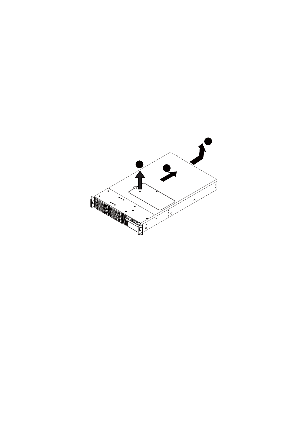
Chassis Removal and Installation
Step 1 Remove the screw on the chassis.
Step 2 Slide toward the top chassis cover.
Step 3 Lift up to remove the top chassis cover.
Step 4 Reverse Step 1, ,2, 3 to replace the chassis cover
Hardware Installation Process
3
1
2
12
GS-R22T61-RH/GS-R22T81-RH Rack Mount Server
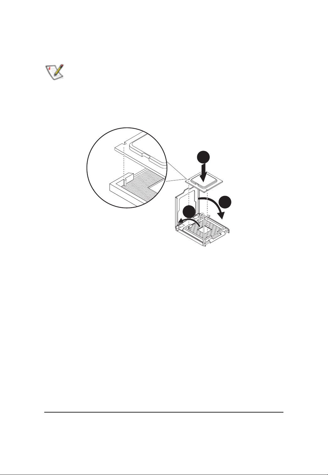
CPU Installation
Please make sure the CPU type and speed that are supported by the motherboard.
Step 1 Raise the metal locking lever on the socket. Insert the CPU with the correct orientation.
Step 2 The CPU only fits in one orientation.
Step 3 Push the metal lever back into locked position.
1
2
3
13
Hardware Installation Process
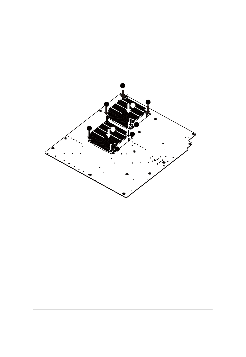
Heat Sink Installation
Step 1 Place the Heat Sink on the CPU. Before putting the heat sink on the CPU, please well
remember to apply the thermal conductivity compound on the CPU.
Step 2 Seat the heat sink in the retention modules with the four screws. Installation completed.
2
2
2
1
1
2
1
1
2
2
2
14
GS-R22T61-RH/GS-R22T81-RH Rack Mount Server
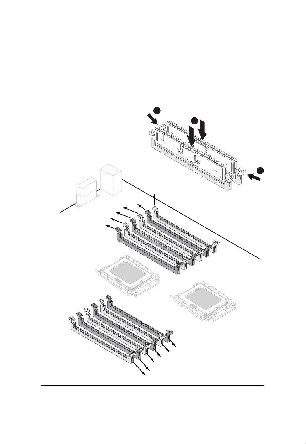
Memory Installation
Step 1. Insert the DIMM memory module vertically into the DIMM slot, and push it down.
Step 2. Close the plastic clip at both edges of the DIMM slots to lock the DIMM module.
NOTE! DIMM must be populated in order starting from DIMMA1/D1 sockets. For dualquad
channel operation, DIMMs must be installed in matched pairs.
Step 3. Reverse the installation steps when you wish to remove the DIMM module.
2
1
2
DIMMF1
DIMME1
DIMME2
DIMMD1
DIMMD2
DIMMF2
CPU2
CPU1
DIMMA2
DIMMA1
DIMMB2
DIMMB1
DIMMC2
DIMMC1
15
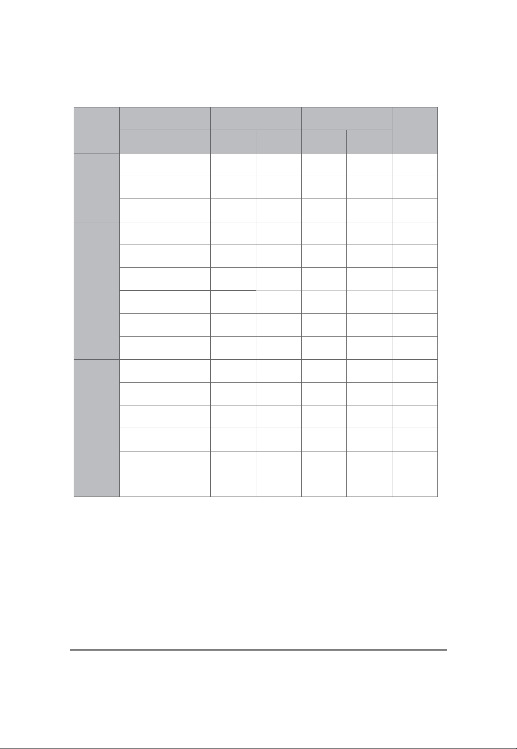
U-DIMM Population Table
Hardware Installation Process
Interleave
mode
Single
Channel
Dual
Channel
Channel A Channel B Channel C
DIMMA1/D1
1GB
2GB
4GB
1GB
2GB
4GB
1GB
2GB
4GB
1GB
2GB
DIMMA2/D2 DIMMB1/E1 DIMMB2/E2 DIMMC1/F1 DIMMC2/F2
1GB
2GB
4GB
1GB
2GB
4GB
1GB
2GB
4GB
1GB
2GB
1GB
2GB
4GB
1GB
2GB
Total
Memory
1GB
2GB
4GB
2GB
4GB
8GB
4GB
8GB
16GB
3GB
6GB
Three
Channel
4GB
1GB
2GB
4GB
1GB
2GB
4GB
4GB
1GB
2GB
4GB
16
1GB
2GB
4GB
4GB
1GB
2GB
4GB
1GB
2GB
4GB
16GB
6GB
12GB
24GB
GS-R22T61-RH/GS-R22T81-RH Rack Mount Server
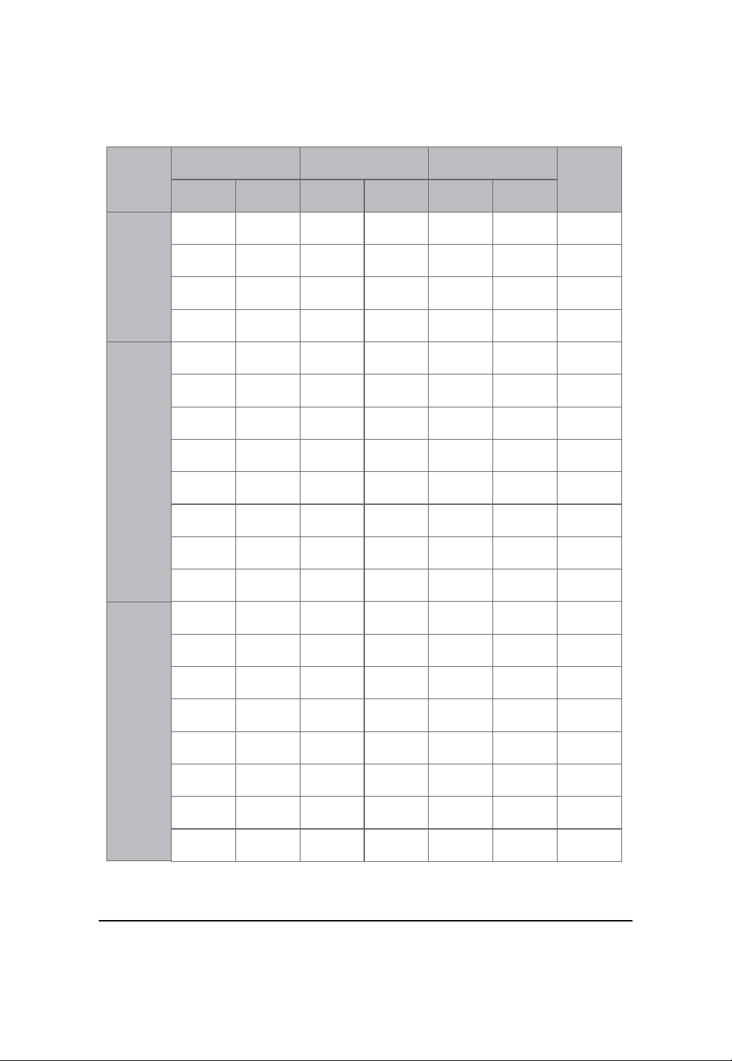
R-DIMM Population Table
Interleave
mode
Single
Channel
Dual
Channel
Channel A Channel B Channel C
DIMMA1/D1
1GB
2GB
4GB
8GB
1GB
2GB
4GB
8GB
1GB
2GB
4GB
DIMMA2/D2 DIMMB1/E1 DIMMB2/E2 DIMMC1/F1 DIMMC2/F2
1GB
2GB
4GB
8GB
1GB 1GB
2GB
4GB
2GB
4GB
1GB
2GB
4GB
Total
Memory
1GB
2GB
4GB
8GB
2GB
4GB
8GB
16GB
4GB
8GB
16GB
Three
Channel
8GB
1GB
2GB
4GB
8GB
1GB
2GB
4GB
8GB
8GB
1GB
2GB
4GB
8GB
8GB
1GB
2GB
4GB
8GB
1GB
2GB
4GB
8GB
17
8GB
1GB
2GB
4GB
8GB
1GB
2GB
4GB
8GB
1GB
2GB
4GB
8GB
1GB
2GB
4GB
8GB
32GB
3GB
6GB
12GB
24GB
6GB
12GB
24GB
48GB
Hardware Installation Process
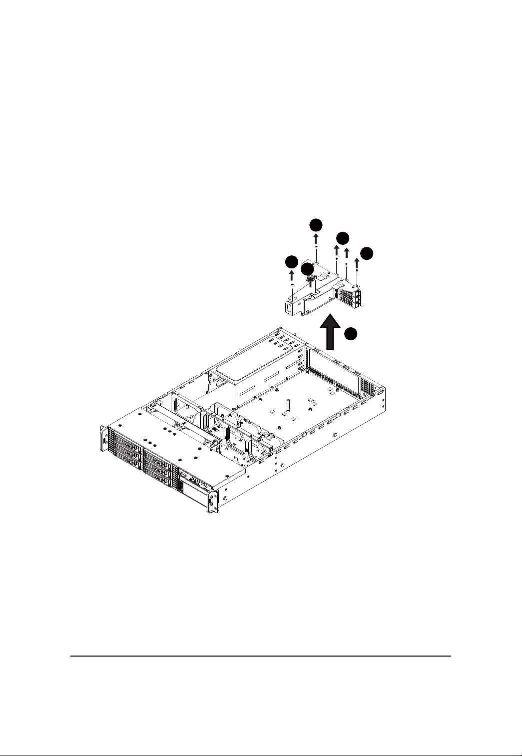
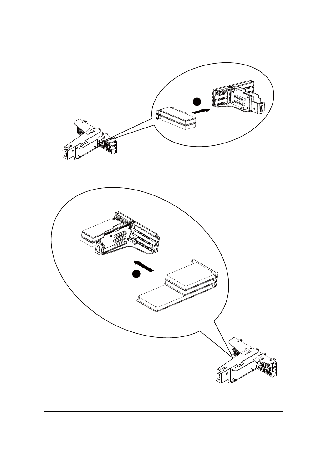
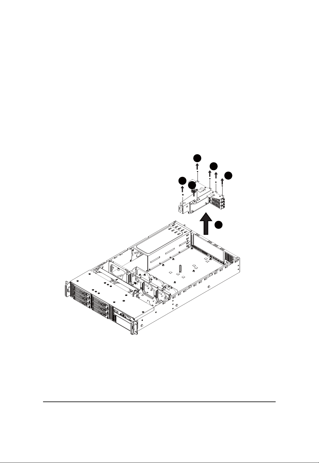
PCI Expansion Card Installation (GC-RLE2N-RH/GC-RFE2N-RH)
Step 1 Loosen the riser bracket screws which attached on on the system.
Step 2 Loosen the rest riser bracket bracket screws.
Step 3 Lift the riser bracket slightly, then pull it out from the server chassis.
Step 4 Slide the expansion card into the slot until the card firmly seats.
Step 5 Slide another expansion card into the slot until the card firmly seats.
Align the riser bracket to the system module.
2
2
2
1
1
3
18
GS-R22T61-RH/GS-R22T81-RH Rack Mount Server
4
5
19
Hardware Installation Process
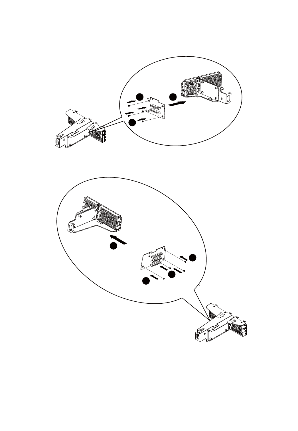
PCI Expansion Card Installation (GC-RFX2N-RH/Optional)
Step 1 Loosen the riser bracket screws which attached on on the system.
Step 2 Loosen the rest riser bracket bracket screws.
Step 3 Lift the riser bracket slightly, then pull it out from the server chassis.
Step 4 Attach the PCI-E card to the riser bracket.
Step 5 Secure the card with screws.
Step 6 Attach anothr PCI-E card to the riser bracket the other side.
Step 7 Secure the card with screws.
Step 8 Align the riser bracket to the system module until it firmly seats.
2
2
2
1
1
3
20
GS-R22T61-RH/GS-R22T81-RH Rack Mount Server
5
4
5
6
7
7
7
21
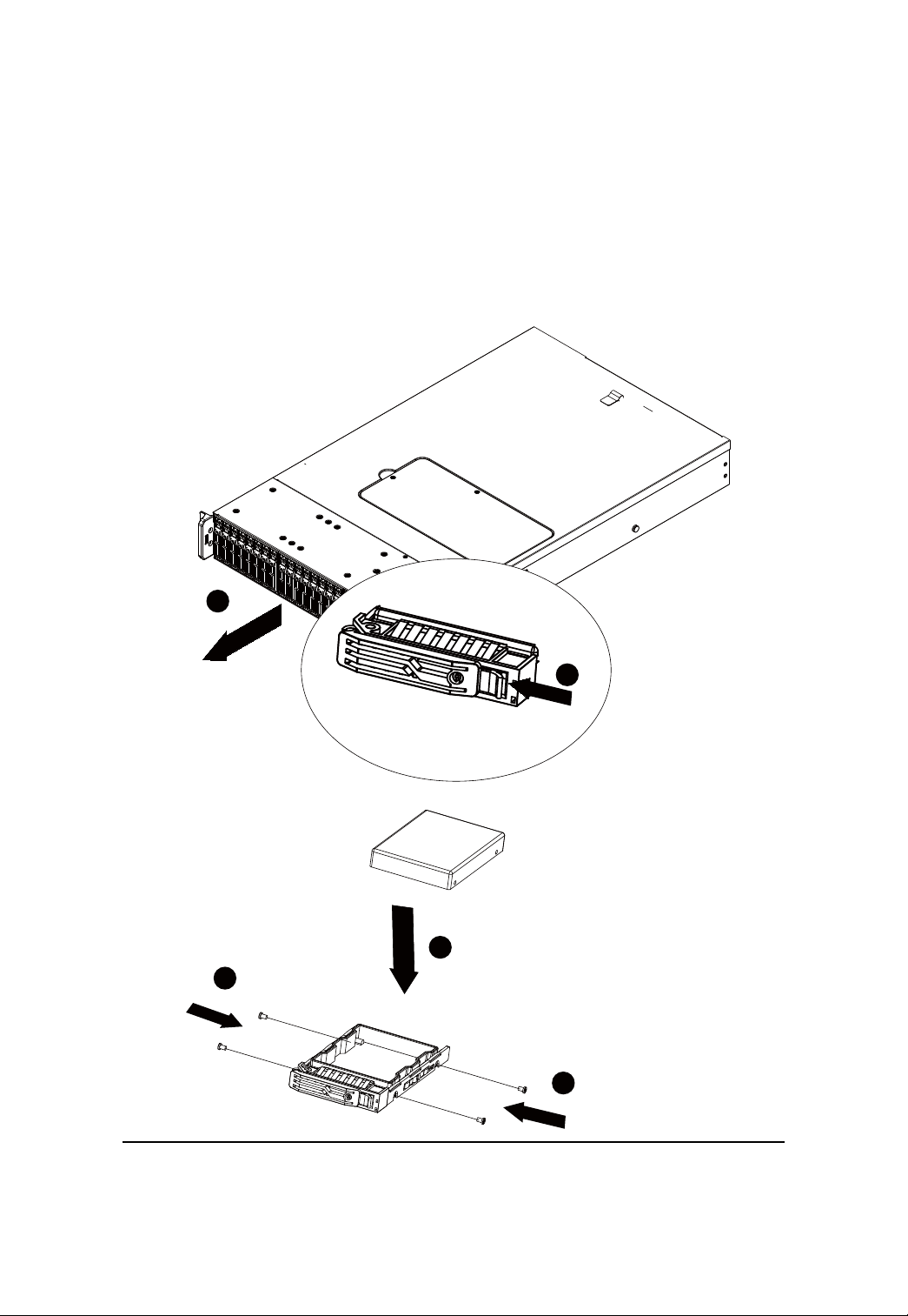
GS-R22T81-RH Hard Disk Drive Installation
Step 1 Press the release button.
Step 2 Pull the blank out of the drive bay.
Step 3 Place hard disk into blank.
Step 4 Secure it with screws.
Slide the blank into the bay until it locks into place. Connect cable and power.
2
Hardware Installation Process
1
3
4
4
22
GS-R22T61-RH/GS-R22T81-RH Rack Mount Server
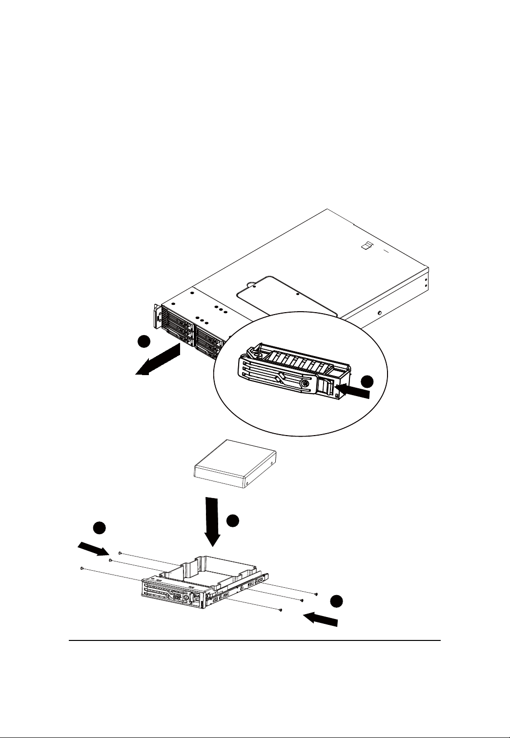
GS-R22T61-RH Hard Disk Drive Installation
Step 1 Press the release button.
Step 2 Pull the blank out of the drive bay.
Step 3 Place hard disk into blank.
Step 4 Secure it with screws.
Slide the blank into the bay until it locks into place. Connect cable and power.
2
1
4
3
4
23
Hardware Installation Process
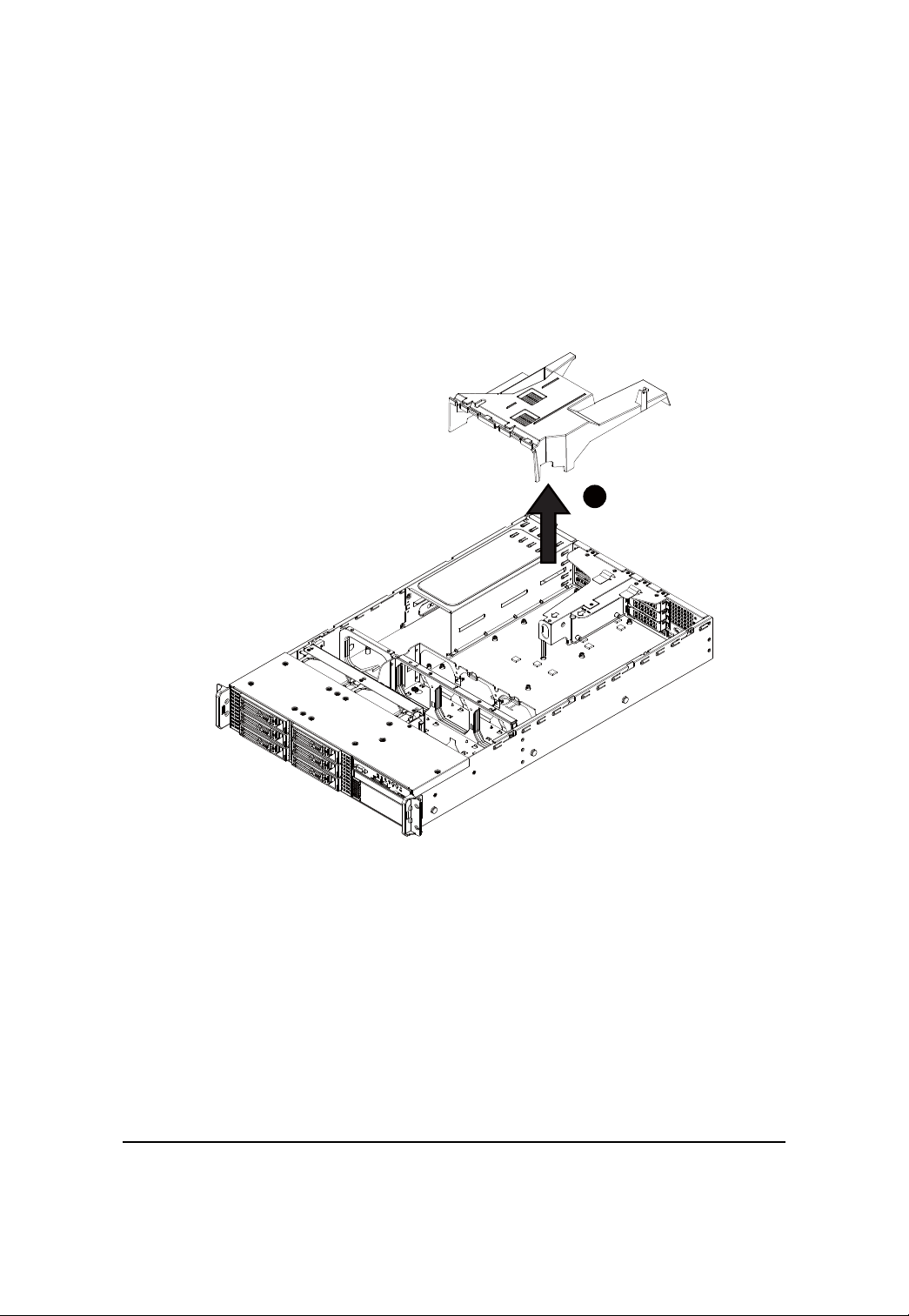
F AN Duct Removal and Installation
Step 1 Lift the fan duct from the chassis.
Step 2 To install fan duct, align the fan duct with the guiding groove. Push down the fan duct into system
until its firmly seats.
1
24
GS-R22T61-RH/GS-R22T81-RH Rack Mount Server
Appearance of GS-R22T61-RH/GS-R22T81-RH
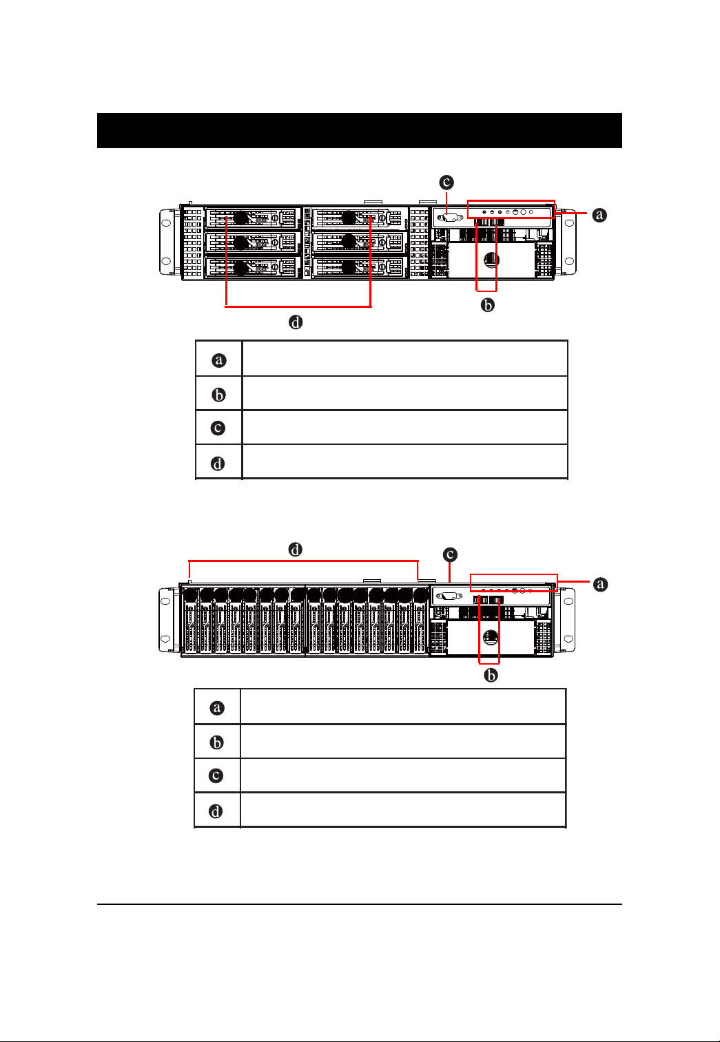
Front View of GS-R22T61-RH (For 3.5 HDDs solution)
2
1
0
5
4
3
Front panel LEDs and Power Button
USB connectors
VGA port
3.5” Hot-Swap SA TA/SAS HDDs
Front View of GS-R22T81-RH (For 2.5 HDDs solution)
10345 678
2
9
1011
121314
15
Front panel LEDs and Power Button
USB connectors
VGA port
2.5” Hot-Swap SA TA/SAS HDDs
NOTE! For Front LED description, please go to Switch and LED Indicators
Introduction section.
Number indicates the HDD installation order.
25
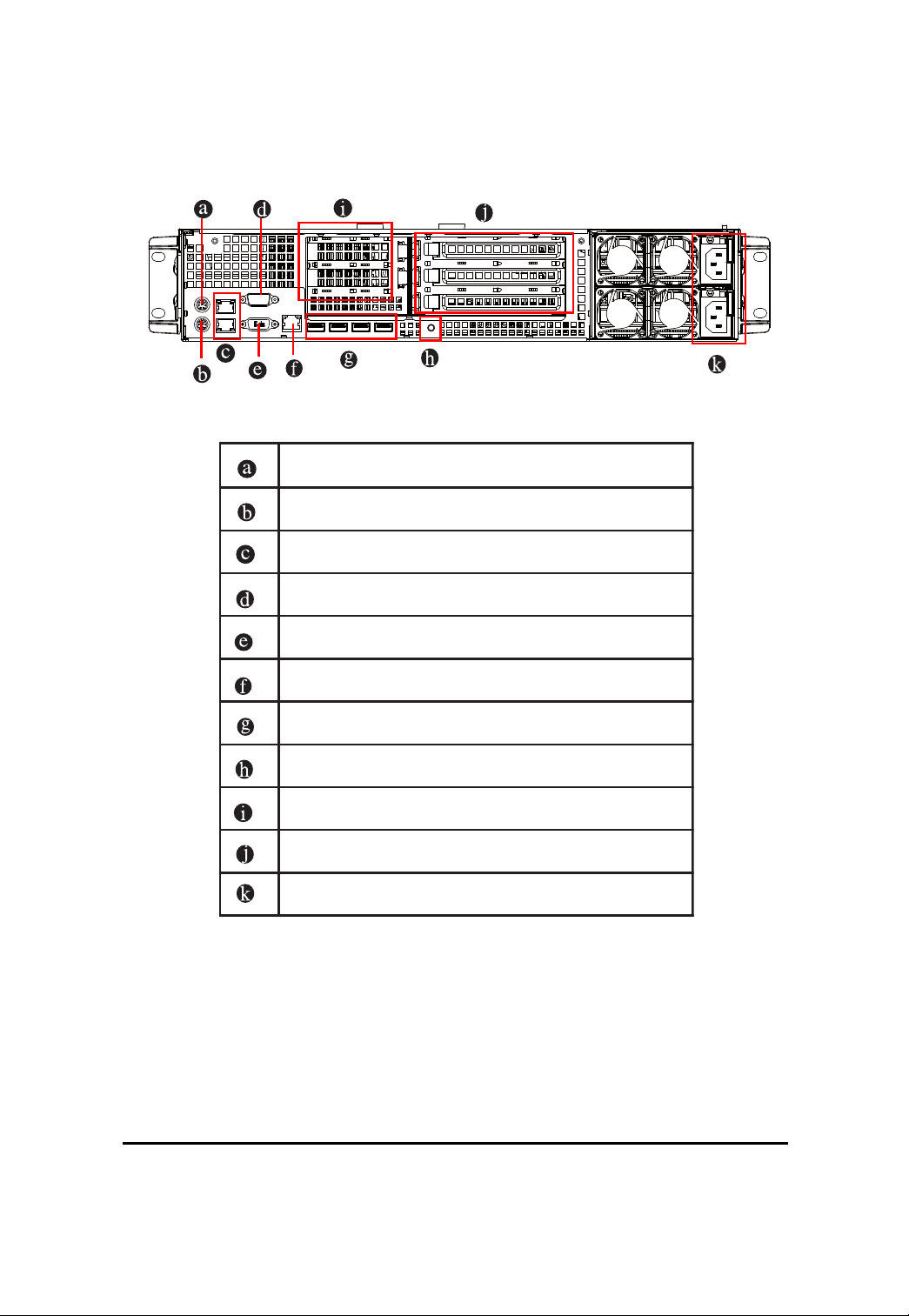
Rear View of GS-R22T61-RH/GS-R22T81-RH
Mouse connector
Keyboard connector
G-LAN ports
COM port
System Appearance
VGA port
10/100 LAN port
USB connectors
ID switch
Low-profile riser slots
Full-height riser slots
Power
26
GS-R22T61-RH/GS-R22T81-RH Rack Mount Server
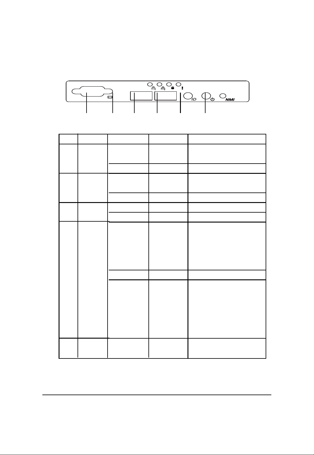
Front Panel LED Indicators
No Indicator
1 LAN1
activity
2 LAN2
activity
3 HDD
activity
4 System
status
5 System ID
Color State Description
Green On Link between system and
network or no access
Green Blink Network access
Green On Link between system and
network or no access
Green Blink Network access
Green Blink HDD access
N/A Off No access
Green On Running or normal operation
Amber On Critical or non-recoverable
condition (Power module or
voltage power supply failure
or critical temperature)
Amber Blink Non-critical condition
N/A Off System not ready
May indicate the following:
POST error
NMI event
Processor or terminator
missing
Blue On System identification is active
Off System identification is disabled
27
LED Description
No Indicator
6 Power
status
Color State Description
Green On System has power supplyto it or
Green Blink System is in ACPI S1 state
N/A Off System is not powered on or in
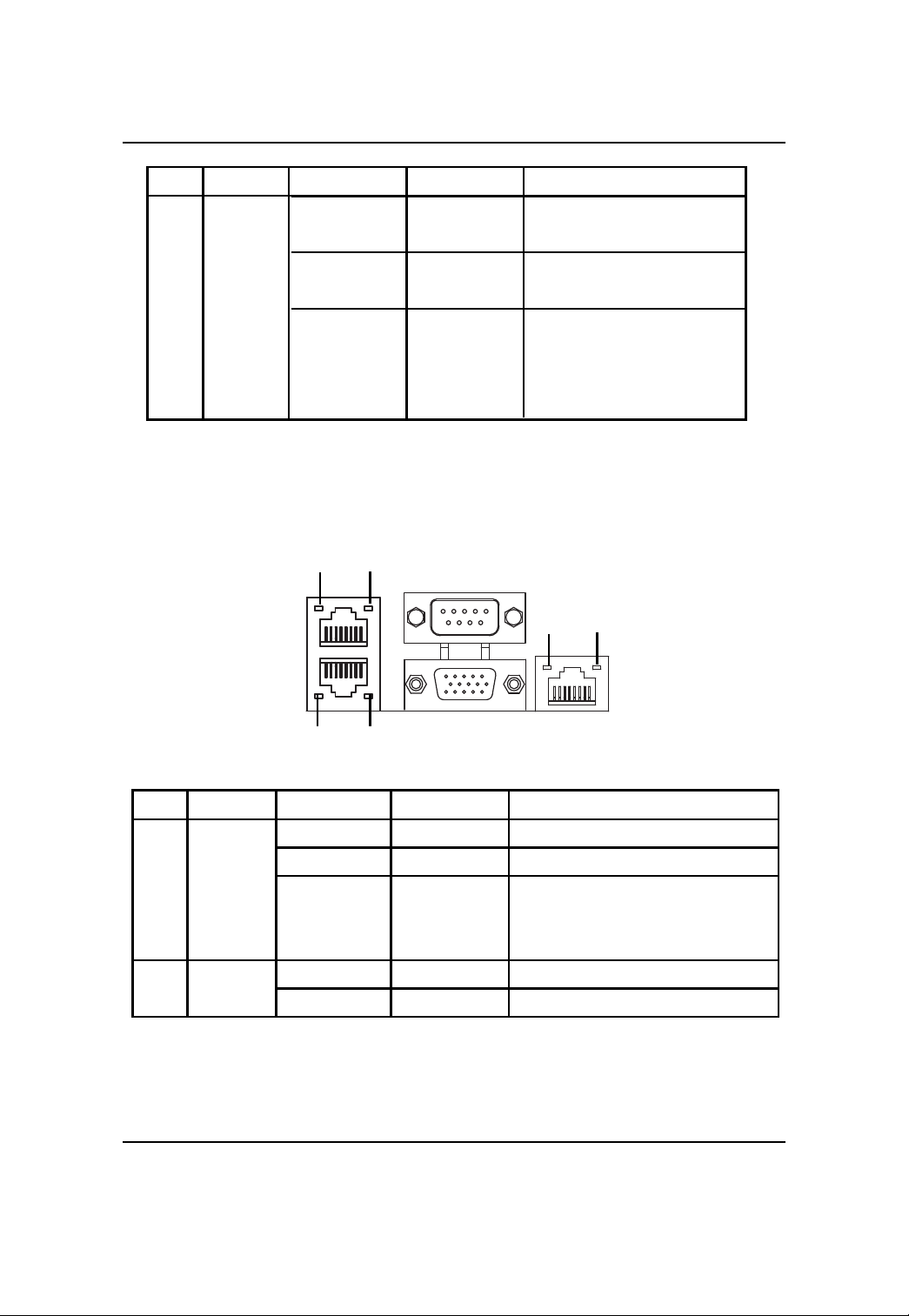
LAN port LED Indicator
ACPI S0 state
(sleep mode)
ACPI S5 state (power off)
System is in ACPI S4 state
(hlbernate mode)
No Name
1 Speed
indicator
2 Link/activity
indicator
Color State Description
N/A Of f 10Mbps connection
Green On 100Mbps connection
Yellow On 1000Mbps connection
Note: The server management port does
not support 1000Mbps connection
Green On Active connection
Green Blink Transmit or receive connection
28
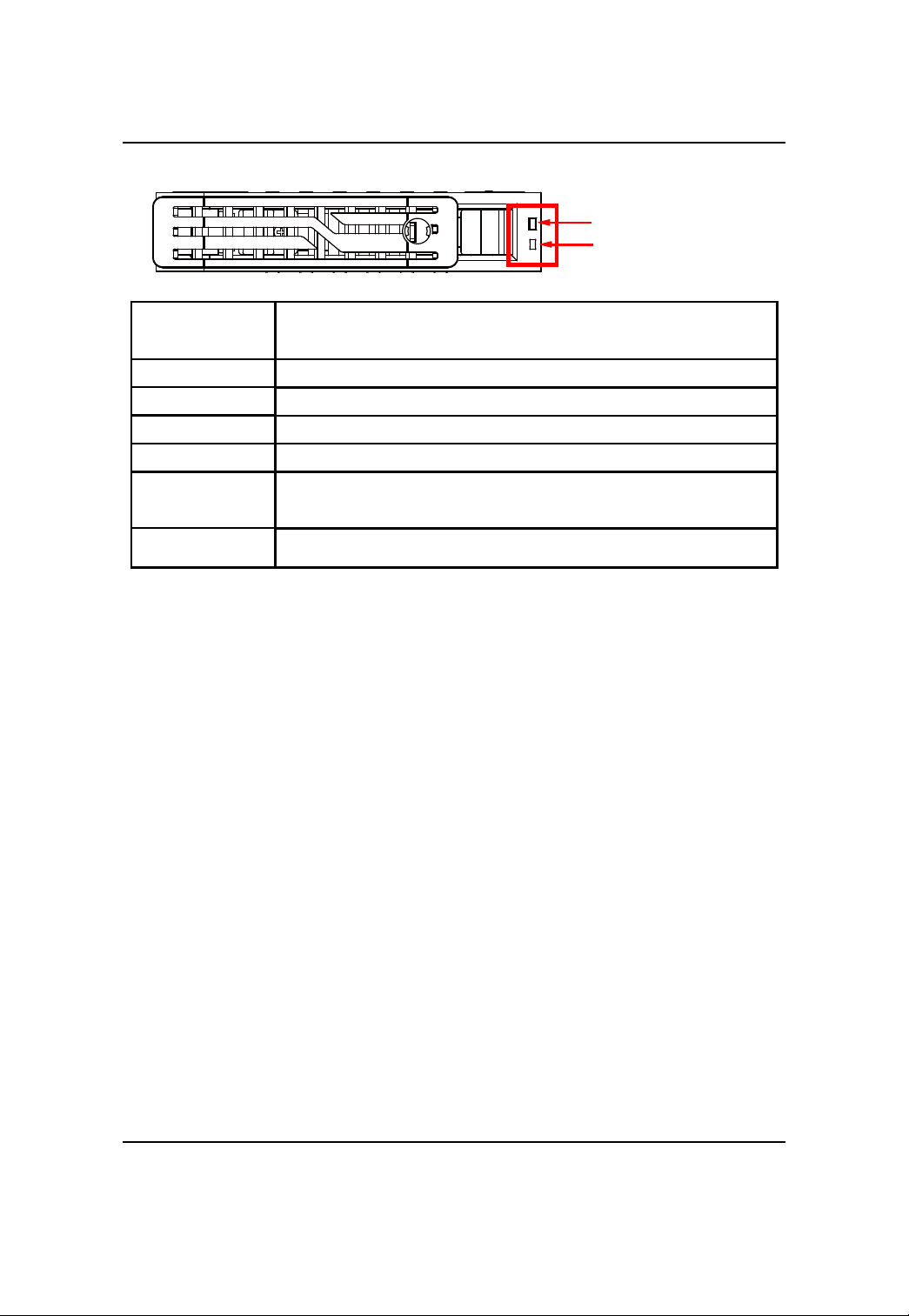
Hard Disk Drive LED Description
LED Description
Description
HDD Prsent
HDD access
HDD failure
HDD removed
HDD connected and
rebuilding data
HDD locate
SAS/SATA HDD indicator
Green Red
On Off
Blink (4Hz) Off
Off On
Off On
On Blink (1 Hz)
Blink (4Hz) Blink (4Hz)
29
GS-R22T61-RH/GS-R22T81-RH Rack Mount Server
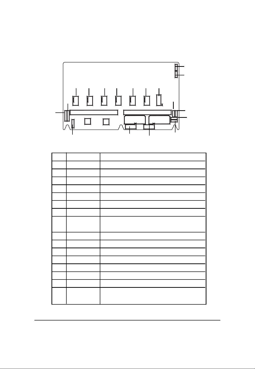
GC-BS28E-RH Back plane board Components Description
(for 2.5”HDD)
10 12 13
1 1 14 15
7
8
9
17
16
22
No Code Description
1 SAS/CON1 SAS 8484 32-pin connector (port 0 ~ 3)
2 SAS/CON2 SAS 8484 32-pin connector (port 4 ~ 7)
3 CN2/X1 Power connector (4-pin)
4 CN1/X1 Power connector (4-pin)
5 J3 SMBUS connector for backplane cascade
6 J1 SMBUS connector to RAID card
7 J2 SMBUS connector to main board (J2)
8 J27 Close 1-2: T wo LED indication (default)
9 J21 LED Power Select
10 SF6 System fan connector for system fan #6
1 1 SF5 System fan connector for system fan #5
12 SF4 System fan connector for system fan #4
13 SF3 System fan connector for system fan #3
14 SF2 System fan connector for system fan #2
15 SF1 System fan connector for system fan #1
16 SGPIO_JP2 SGPIO Connector
17 SGPIO_JP1 SGPIO Connector
2
6
Close 2-3: Single LED indication (backward support)
1
4
5
19
3
18
20
21
30
 Loading...