

GIGABYTE GS-R227E-RH Owner's Manual

GS-R227E-RH
2U Rack Mount Server
System Installation Guide
Dual Intel® Xeon LGA771 Processor Serverboard
Rev. 1.0

GS-R227E-RH Rack Mount Server
Table of Content
Safety, Care and Regulatory Information................................................4
Introduction..............................................................................................8
Contents Packages ................................................................................8
Chapter 1 Features Summary.................................................................9
Chapter 2 System Hardware Installation ............................................... 11
Step 2-1: Chassis Removal and Installation .................................................................11
Step 2-2: CPU Installation............................................................................................... 12
Step 2-3: Heat Sink Installation....................................................................................... 13
Step 2-4: Memory Installation ........................................................................................ 14
Step 2-5: PCI Expansion Card Installation.................................................................... 15
Step 2-6: Hard Disk Drive Installation ............................................................................ 16
Step 2-7: FAN Duct Removal and Installation.............................................................. 17
Chapter 3 Appearance of GS-R227E-RH.............................................18
3-1: Front View of GS-R227E-RH ................................................................................. 18
3-2: Rear View of GS-R227E-RH.................................................................................. 19
3-3: Switch and LED Indicators Introduction ................................................................. 20
3-4: LAN LED Description............................................................................................... 21
3-5: Connector Icon Description..................................................................................... 22
Chapter 4 Motherboard Jumper Setting ...............................................23
4-1: GA-7BESV1-RH Motherboard Jumpper Setting.................................................... 23
Chapter 5 BIOS Setup ..........................................................................25
Main........................................................................................................... 27
Advanced ................................................................................................... 30
Advanced Processor Options ........................................................................................ 31
Memory Configuration ..................................................................................................... 33
PCI Configuration............................................................................................................. 35
I/O Device Configuration................................................................................................. 36
Advanced Chipset Control ............................................................................................. 39
Security ...................................................................................................... 42
2

Table of Content
Server.........................................................................................................44
Console Redirection........................................................................................................ 45
Boot............................................................................................................ 49
Exit .............................................................................................................50
3

GS-R227E-RH Rack Mount Server
Safety, Care and Regulatory Information
/ Important safety information
Read and follow all instructions marked on the product and in the documentation before you operate
your system. Retain all safety and operating instructions for future use.
* The product should be operated only from the type of power source indicated on the rating label.
* If your computer has a voltage selector switch, make sure that the switch is in the proper position for
your area. The voltage selector switch is set at the factory to the correct voltage.
* The plug-socket combination must be accessible at all times because it serves as the main disconnecting device.
* All product shipped with a three-wire electrical grounding-type plug only fits into a grounding-type power
outlet. This is a safety feature. The equipment grounding should be in accordance with local and national
electrical codes. The equipment operates safely when it is used in accordance with its marked electrical
ratings and product usage instructions
* Do not use this product near water or a heat source.
* Set up the product on a stable work surface or so as to ensure stability of the system.
* Openings in the case are provided for ventilation. Do not block or cover these openings. Make sure you
provide adequate space around the system for ventilation when you set up your work area. Never insert
objects of any kind into the ventilation openings.
* To avoid electrical shock, always unplug all power cables and modem cables from the wall outlets
before removing covers.
* Allow the product to cool before removing covers or touching internal components.
/ Precaution for Product with Laser Devices
Observe the following precautions for laser devices:
* Do not open the CD-ROM drive, make adjustments, or perform procedures on a laser device other than
those specified in the product's documentation.
* Only authorized service technicians should repair laser devices.
/ Precaution for Product with Modems, Telecommunications, ot Local Area
Network Options
Observe the following guidelines when working with options:
* Do not connect or use a modem or telephone during a lightning storm. There may be a risk of electrical
shock from lightning.
4

Safety Information
* To reduce the risk of fire, use only No. 26 A WG or larger telecommunications line cord.
* Do not plug a modem or telephone cable into the network interface controller (NIC) receptacle.
* Disconnect the modem cable before opening a product enclosure, touching or installing internal
components, or touching an uninsulated modem cable or jack.
* Do not use a telephone line to report a gas leak while you are in the vicinity of the leak.
/ Federal Communications Commission (FCC) Statement
Warning
This is a class A product. In a domestic environment this product may cause radio
interference
In which case the user may be required to take adequate measures.
Note: This equipment has been tested and found to comply with the limits for a Class B digital device,
pursuant to Part 15 of the FCC Rules. These limits are designed to provide reasonable protection against
harmful interference when the equipment is operated in a commercial environment. This equipment
generates, uses, and can radiate radio frequency energy and, if not installed and used in accordance with
the instruction manual, may cause harmful interference to radio communications. Operation of this
equipment in a residential area is likely to cause harmful interference in which case the user will be
required to correct the interference at his own expense.
Properly shielded and grounded cables and connectors must be used in order to meet FCC emission
limits. Neither the provider nor the manufacturer are responsible for any radio or television interference
caused by using other than recommended cables and connectors or by unauthorized changes or
modifications to this equipment. Unauthorized changes or modifications could void the user's authority to
operate the equipment.
This device complies with Part 15 of the FCC Rules. Operation is subject to the following two conditions:
(1) this device may not cause harmful interference, and
(2) this device must accept any interference received, including interference that may cause undesired
operation.
/ FCC part 68 (applicable to products fitted with USA modems)
The modem complies with Part 68 of the FCC Rules. On this equipment is a label that contains, among
other information, the FCC registration number and Ringer Equivalence Number (REN) for this equipment.
Y ou must, upon request, provide this information to your telephone company .
If your telephone equipment causes harm to the telephone network, the Telephone Company may
discontinue your service temporarily. If possible, they will notify in advance. But, if advance notice is not
practical, you will be notified as soon as possible. Y ou will be informed of your right to file a complaint with
5

GS-R227E-RH Rack Mount Server
the FCC.
Y our telephone company may make changes in its facilities, equipment, operations, or procedures that
could affect proper operation of your equipment. If they do, you will be notified in advance to give you an
opportunity to maintain uninterrupted telephone service.
The FCC prohibits this equipment to be connected to party lines or coin-telephone service.
The FCC also requires the transmitter of a FAX transmission be properly identified (per FCC Rules Part
68, Sec. 68.381 (c) (3)).
/ for Canadian users only /
/ Canadian Department of Communications Compliance Statement
This digital apparatus does not exceed the Class B limits for radio noise emissions from digital
apparatus as set out in the radio interference regulations of Industry Canada.
Le present appareil numerique n'emet pas de bruits radioelectriques depassant les limites applicables aux
appareils numeriques de Classe B prescrites dans le reglement sur le brouillage radioelectrique edicte par
Industrie Canada.
/ DOC notice (for products fitted with an Industry Canada-compliant modem)
The Canadian Department of Communications label identifies certified equipment. This certification
means that the equipment meets certain telecommunications network protective, operational and safety
requirements. The Department does not guarantee the equipment will operate to the user satisfaction.
Before installing this equipment, users ensure that it is permissible to be connected to the facilities of the
local T elecommunications Company . The equipment must also be installed using an acceptable method
of connection. The customer should be aware that compliance with the above conditions might not prevent
degradation of service in some situations.
Repairs to certified equipment should be made by an authorized Canadian maintenance facility designated
by the supplier. Any repairs or alterations made by the user to this equipment, or equipment malfunctions,
may give the telecommunications company cause to request the user to disconnect the equipment.
Users should ensure for their own protection that the electrical ground connections of the power utility,
telephone lines and internal metallic water pipe system, if resent are connected together. This precaution
may be particularly important in rural areas.
Caution: Users should not attempt to make such connections themselves, but should contact the
appropriate electric inspection authority, or electrician, as appropriate.
6
Safety Information
NOTICE: The Load Number (LN) assigned to each terminal device denotes the percentage of the total
load to be connected to a telephone loop which is used by the device, to prevent overloading. The
termination on a loop may consist of any combination of devices subject only to the requirement that the
sum of the Load Numbers of all the devices does not exceed 100.
/ for European users only /
CAUTION
Danger of explosion if battery is incorrectly
replaced.
Replace only with the same or equivalent
type recommended by the manufacturer.
Dispose of used batteries according to the
manufacturer’s instructions.
Class A Warning statement
WARNING
This is class A products. In a domestic
environment this product may cause radio
interference in which case the user may be
required to take adequate measures.
7

GS-R227E-RH Rack Mount Server
Introduction
Welcome to Gigabyte GS-R227E-RH Rack mount Server System Installation Guide. The guide
provides instructions for configuration hardware for the GS-R227E-RH your system.
This installation guide will assist you in installing all the essential components for the sever system.
For your protection, please read and undertand all of the safety and operating instructions regarding your
Gigabyte Server and retain for future reference. The procedures in this guidebook assume that your are
a system or network administrator experienced in installing similar hardware.
Contents Packages
When opening the package, please ensure the system components are not damaged during the shipping.
Using the following checklist to verify the contents. If any component is missing or damaged in the
system, please contact your vendor immediately.
; Chassis ; GA-7BESV1-RH Motherboard (Installed)
; Power Supply (Installed) ; FAN Duct x 1
; CPU Heat Sink x 2 (Optional) ; Silm type DVD Combo (Installed)
; Case Handle Kit x 2
; GS-R227E-RH Quick Refernece Guide
; Driver CD for motherboard driver & utility
* The items listed above are for reference only, and are subject to change without notice.
8

Feature Summary
Chapter 1 Features Summary
Motherboard y GA-7BESV1-RH
Processor Supported y Supports dual Intel® Xeon® processors
®
y Intel Xeon
y Supports 1066/1333MHz FSB
Chipset y Intel® 5000 Chipset
y Intel® 6321ESB
System Memory:
Memory Capacity y 8 x Fully Buffered DIMM (FBD) sockets up to 32GB
Memory Type y Registered 667memory
DIMM Size y Support 256MB, 512MB, 1GB, and 2GB memory
Error Correction: y Single-bit Errors Correction, Multiple Bit Errors Detection
Expansion Slot y 1 Riser card supports 2 PCI-E x8, 2 PCI-E x4 (x1 bandwidth)
and 1 PCI-X 64/100MHz add-on cards
SATA RAID controller y Intel® 6321ESB
y Supports Intel Software SW RAID 0/1/10 (Windows only)
Cooling Fans: y 5 X System Fan
Integrated LANs:
Controller y Intel® 82563EBGbE controller
Integrated Graphics:
Controller y XGI Volari Z9s
Graphics Memory y 16MB DDR2
Mass Storage System y 6 x 3.5” Hot-Swap SATA HDDs
y 1 x DVD Combo
Super I/O
Controller y ITE IT8718F Super I/O
Built-in I/O y 2 x Serial port (1 at front panel)
y 4 x USB 2.0 dual-port connector (2 at front panel)
y 1 x VGA connector
y 2 x RJ45 LAN ports
y P/S 2 Keyboard and Mouse Connectors
System BIOS:
BIOS Type y Phoenix BIOS on 8Mb flash ROM
Dual-Core/Quad-Core processor in LGA 771 socket
9

GS-R227E-RH Rack Mount Server
Server Management Functions: (Optional device)
BMC Chip y H8S IPMI 2.0 controller
Failure Detection y IPMI 2.0 specification of Server management
Event Logging y 32KB Nonvolatile Memory to Log System Failure Events
Remote Management y Follow the IPMI 2.0 specification of Server management
Environment
o
Ambient T emperature y Operating T emperature: 5
y Non-operating T emperature: 0
C to 35oC
o
C to 50oC
Relative Humidity y 10-80% operating Humidity at 30o C
System Dimention: y 425mm x 710mm x 86.4mm
Electrical Power Supply y Single Power Supply 700W
10
Hardware Installation Process
Chapter 2 System Hardware Installation
Please observe the safety information in chapter “Important Safety Information”
Do not expose the server to extreme environmental conditions. Protect it from dust,
humidity, and heat.
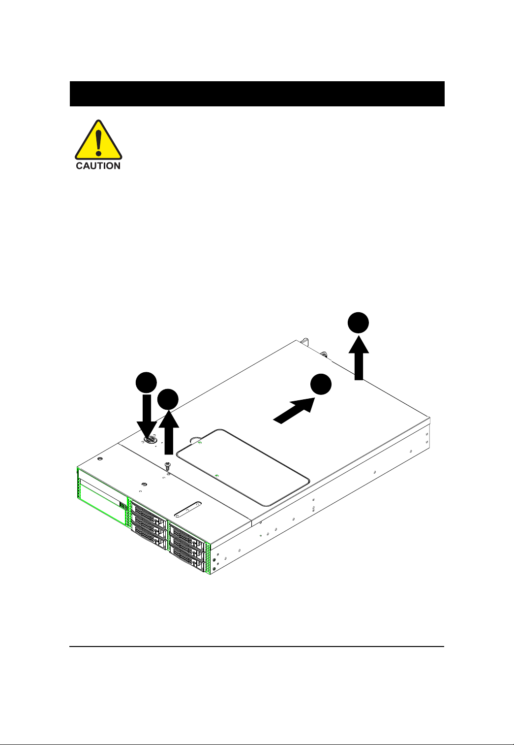
Step 2-1: Chassis Removal and Installation
Step 1 Loosen the screw on the front chassis cover.
Step 2 Push down the indentation located at the side of the back chassis.
Step 3 Slide toward the top chassis cover.
Step 4 Lift up to remove the top chassis cover.
Step 5 Reverse Step 1, ,2, 3, 4 to replace the chassis cover
4
2
3
1
11
GS-R227E-RH Rack Mount Server
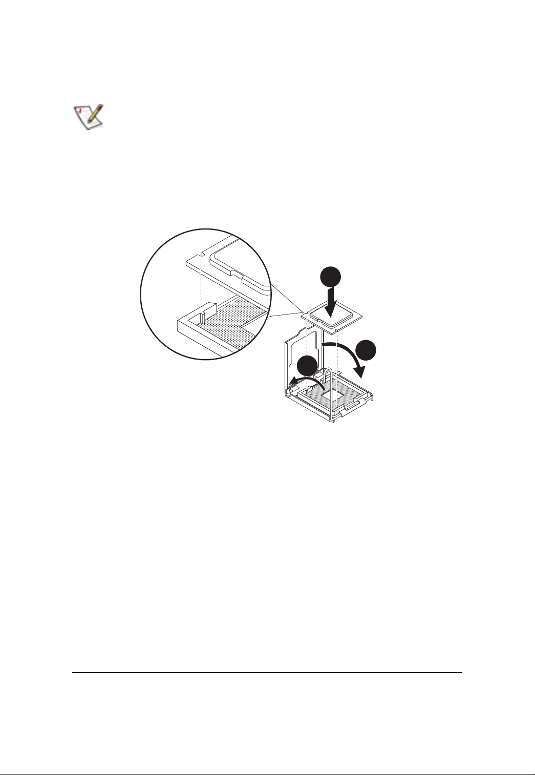
Step 2-2: CPU Installation
Please make sure the CPU type and speed that are supported by the motherboard.
Step 1 Raise the metal locking lever on the socket. Insert the CPU with the correct orientation.
Step 2 The CPU only fits in one orientation.
Step 3 Push the metal lever back into locked position.
1
2
3
12
Hardware Installation Process
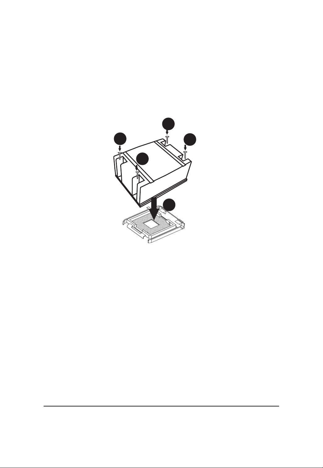
Step 2-3: Heat Sink Installation
Step 1 Place the Heat Sink on the CPU. Before putting the heat sink on the CPU, please well
remember to apply the thermal conductivity compound on the CPU.
Step 2 Seat the heat sink in the retention modules with the four screws. Installation completed.
2
2
2
2
1
13
GS-R227E-RH Rack Mount Server
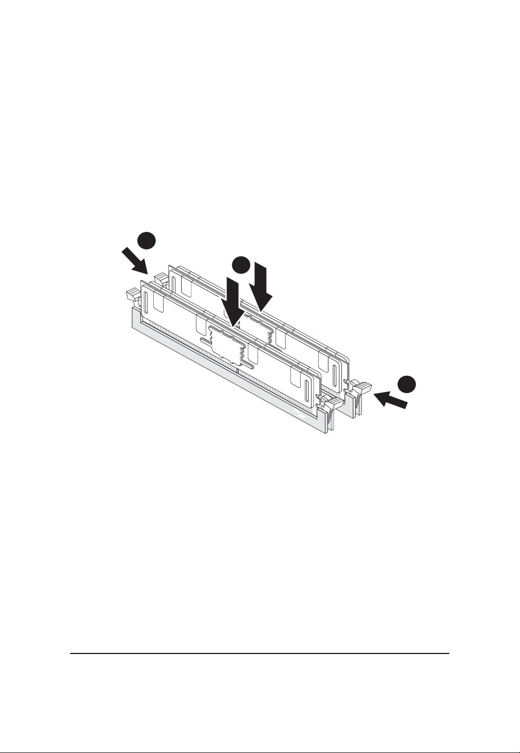
Step 2-4: Memory Installation
Step 1. Insert the DIMM memory module vertically into the DIMM slot, and push it down.
Step 2. Close the plastic clip at both edges of the DIMM slots to lock the DIMM module.
NOTE! DIMM must be populated in order starting from DIMM8 socket. For dual-channel
operation, DIMMs must be installed in matched pairs.
Step 3. Reverse the installation steps when you wish to remove the DIMM module.
2
1
14
2
GS-R227E-RH Rack Mount Server
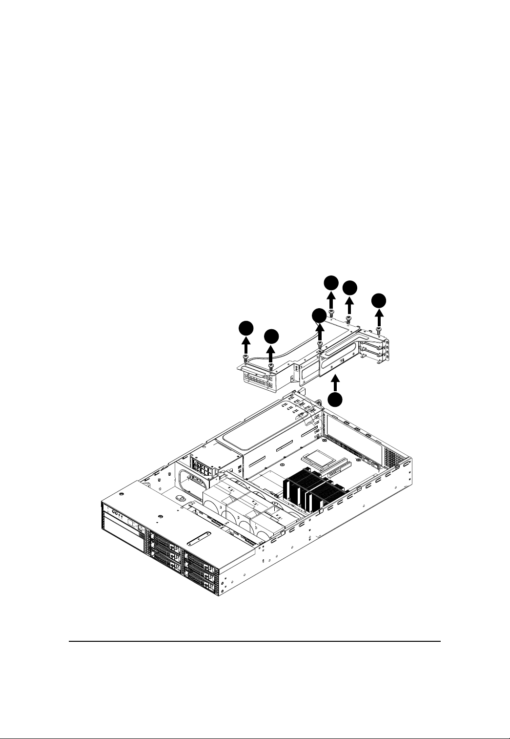
Step 2-5: PCI Expansion Card Installation
GS-R227E-RH provides expansion riser slots for one PCI-E x8 slot; and one with PCI-E x8 slot (at x1
bandwidth). T o install the peripheral, please go through the following steps.
Step 1 Loosen the two riser bracket screws. (See illustrated below)
Step 2 Loosen another four riser bracket screws. (See illustrated below)
Step 3 Lift the riser bracket slightly, then pull it out from the server chassis.
Align the expansion card with the guiding groove. Slide the expansion card into the slot until the
card firmly seats.
Step 4 Align the riser bracket to the system module.
2
2
1
1
2
2
15
3
Hardware Installation Process
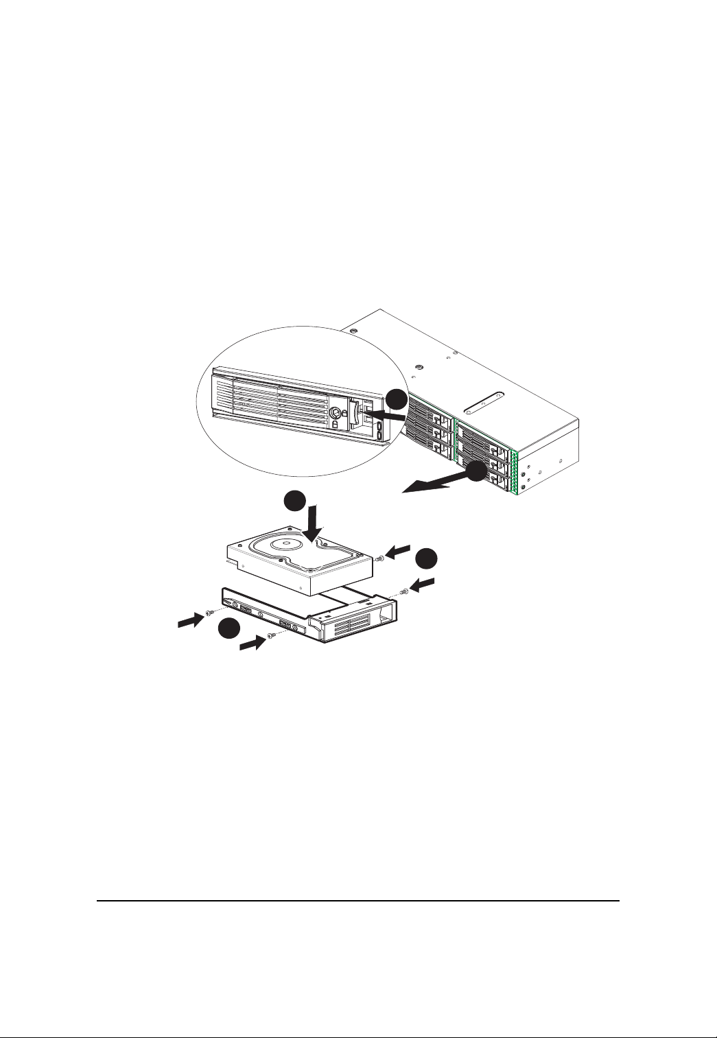
Step 2-6: Hard Disk Drive Installation
Step 1 Press the release button.
Step 2 Pull the blank out of the drive bay.
Step 3 Slide hard disk into blank.
Step 4 Secure it with screws.
Step 5 Slide the blank into the bay until it locks into place. Connect cable and power.
1
2
3
4
4
16
Hardware Installation Process
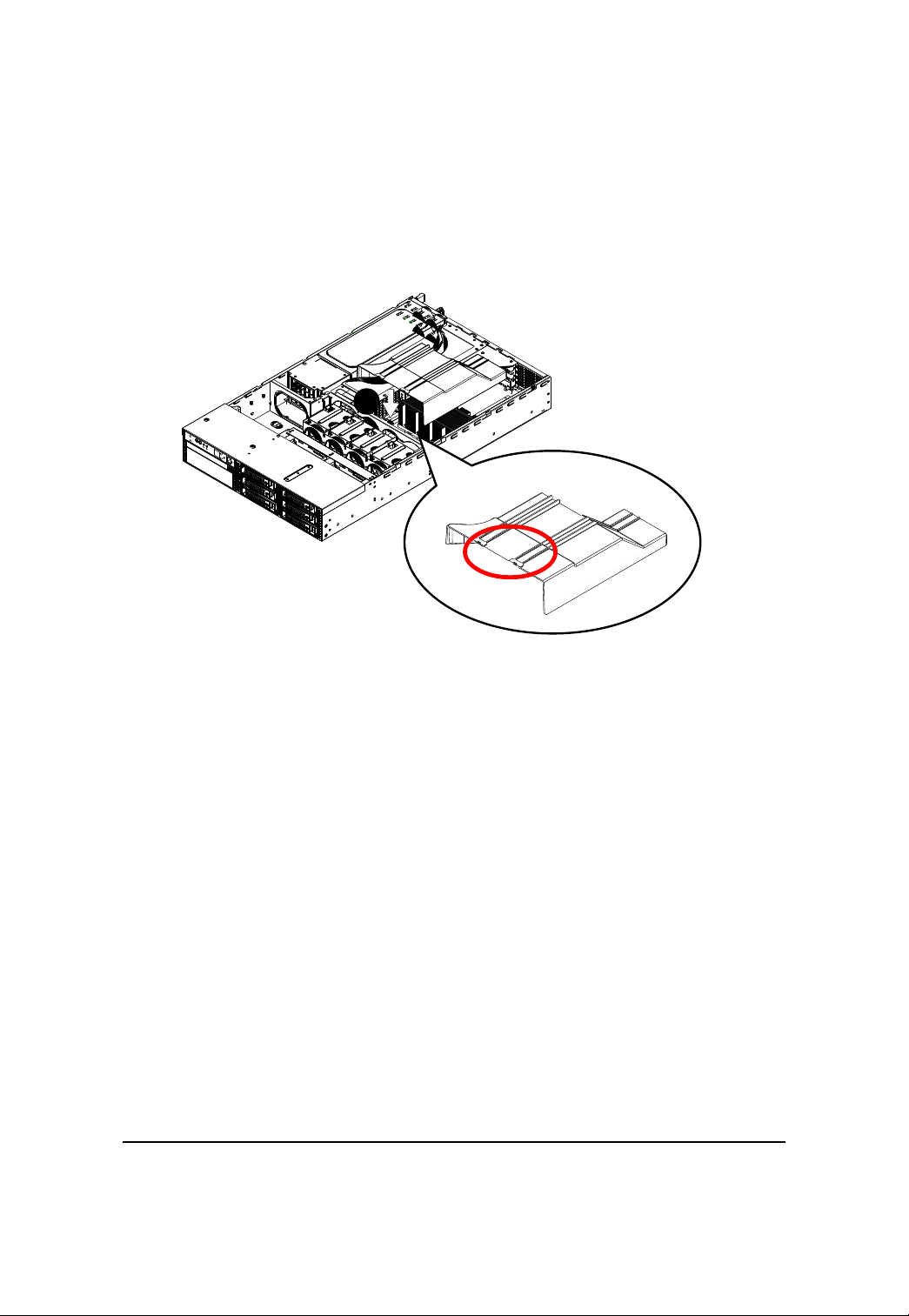
Step 2-7: F AN Duct Removal and Installation
Step 1 Align the fan duct with the guiding groove. Push down the fan duct into system ntil the
its firmly seats.
1
Guiding groove
17
 Loading...