

Page 1

GIGABYTE
GS-R12T4H2-RH
1U Rack Mount Server
Service Guide
Dual Intel® Xeon LGA1366 Processor Serverboard
Rev. 1.0
Page 2

Preface
Before using this information and the product it supports, please read the following general information.
1. This Service Guide provides you with all technical information relating to the BASIC
CONFIGURA TION decided for GIGABYTE’s “global” product offering. To better fit local market
requirements and enhance product competitiveness, your regional office MA Y have decided to
extend the functionality of a machine (e.g. add-on card, modem, or extra memory capability).
These LOCALIZED FEATURES will NOT be covered in this generic service guide. In such
cases, please contact your regional offices or the responsible personnel/channel to provide you
with further technical details.
2. Please note WHEN ORDERING FRU P ARTS, you should check the most up-to-date information
available on your regional web or channel. For whatever reason, if a part number change is made,
it will not be noted in the printed Service Guide. For GIGABYTE-AUTHORIZED SERVICE
PROVIDERS, your GIGABYTE office may have a DIFFERENT part number code to those
given in the FRU list of this printed Service Guide. You MUST use the list provided by your
regional GIGABYTE office to order FRU parts for repair and service of customer machines
Page 3

GS-R12T4H2-RH Rack Mount Server
Table of Contents
Preface....................................................................................................2
Safety, Care and Regulatory Information................................................5
System Specification..............................................................................9
System Hardware Installation................................................................ 11
Remove the chassis cover. .......................................................................................... 12
Installing the Processor................................................................................................... 13
Installing the Heat Sink .................................................................................................... 14
Installing the Memeory Module...................................................................................... 15
Installing the PCI Expansion Card................................................................................. 19
Installing the Hard Disk Drive ......................................................................................... 21
HDD Security Lock.......................................................................................................... 22
Installing and Replacing the FAN Duct.......................................................................... 23
Replacing the FAN Assemblly ...................................................................................... 24
Replacing the Motherboard............................................................................................. 25
Replacing the Power Supply ........................................................................................ 26
Replacing the Chassis Cover ...................................................................................... 28
Appearance of GS-R12T4H2-RH ..........................................................29
Front View of GS-R12T4H2-RH..................................................................................... 29
Rear View of GS-R12T4H2-RH ..................................................................................... 30
Front Panel LED Indicator ............................................................................................... 31
LAN port LED Indicator.................................................................................................... 33
Hard Disk Drive LED Description ................................................................................... 34
GC-BS14U-RH Back plane board Components .......................................................... 35
System Block Diagram................................................................................................... 36
Connector Icon Description............................................................................................. 37
Motherboard Placement and Jumper Setting ......................................38
GA-7TTSE-RH Motherboard Component...................................................................... 38
Jumper Setting ................................................................................................................. 40
Expansion Card Components Description .................................................................... 42
BIOS Setup...........................................................................................43
Main...........................................................................................................45
3
Page 4

Table of Content
Advanced ................................................................................................... 47
Processor Configuration.................................................................................................. 48
Processor Power Management ..................................................................................... 51
Memory Configuration ..................................................................................................... 54
Advanced Chipset Configuration ................................................................................... 56
PCI Configuration............................................................................................................. 60
SATA Configuration.......................................................................................................... 62
I/O DeviceConfiguration .................................................................................................. 65
Boot DeviceConfiguration................................................................................................ 67
Thermal and Acoustic Configuration.............................................................................. 69
Power.........................................................................................................71
Security ...................................................................................................... 72
Server......................................................................................................... 74
System Management...................................................................................................... 75
Console Redirection........................................................................................................ 77
Boot............................................................................................................79
Exit .............................................................................................................80
4
Page 5

GS-R12T4H2-RH Rack Mount Server
Safety, Care and Regulatory Information
Important safety information
Read and follow all instructions marked on the product and in the documentation before you operate
your system. Retain all safety and operating instructions for future use.
* The product should be operated only from the type of power source indicated on the rating label.
* If your computer has a voltage selector switch, make sure that the switch is in the proper position for
your area. The voltage selector switch is set at the factory to the correct voltage.
* The plug-socket combination must be accessible at all times because it serves as the main disconnecting device.
* All product shipped with a three-wire electrical grounding-type plug only fits into a grounding-type power
outlet. This is a safety feature. The equipment grounding should be in accordance with local and national
electrical codes. The equipment operates safely when it is used in accordance with its marked electrical
ratings and product usage instructions
* Do not use this product near water or a heat source.
* Set up the product on a stable work surface or so as to ensure stability of the system.
* Openings in the case are provided for ventilation. Do not block or cover these openings. Make sure you
provide adequate space around the system for ventilation when you set up your work area. Never insert
objects of any kind into the ventilation openings.
* To avoid electrical shock, always unplug all power cables and modem cables from the wall outlets
before removing covers.
* Allow the product to cool before removing covers or touching internal components.
Precaution for Product with Laser Devices
Observe the following precautions for laser devices:
* Do not open the CD-ROM drive, make adjustments, or perform procedures on a laser device other than
those specified in the product's documentation.
* Only authorized service technicians should repair laser devices.
Precaution for Product with Modems, Telecommunications, ot Local Area
Network Options
Observe the following guidelines when working with options:
* Do not connect or use a modem or telephone during a lightning storm. There may be a risk of electrical
shock from lightning.
5
Page 6

Safety Information
* To reduce the risk of fire, use only No. 26 AWG or larger telecommunications line cord.
* Do not plug a modem or telephone cable into the network interface controller (NIC) receptacle.
* Disconnect the modem cable before opening a product enclosure, touching or installing internal
components, or touching an uninsulated modem cable or jack.
* Do not use a telephone line to report a gas leak while you are in the vicinity of the leak.
Federal Communications Commission (FCC) Statement
Warning
This is a class A product. In a domestic environment this product may cause radio
interference
In which case the user may be required to take adequate measures.
Note: This equipment has been tested and found to comply with the limits for a Class A digital device,
pursuant to Part 15 of the FCC Rules. These limits are designed to provide reasonable protection against
harmful interference when the equipment is operated in a commercial environment. This equipment
generates, uses, and can radiate radio frequency energy and, if not installed and used in accordance with
the instruction manual, may cause harmful interference to radio communications. Operation of this
equipment in a residential area is likely to cause harmful interference in which case the user will be
required to correct the interference at his own expense.
Properly shielded and grounded cables and connectors must be used in order to meet FCC emission
limits. Neither the provider nor the manufacturer are responsible for any radio or television interference
caused by using other than recommended cables and connectors or by unauthorized changes or
modifications to this equipment. Unauthorized changes or modifications could void the user's authority to
operate the equipment.
This device complies with Part 15 of the FCC Rules. Operation is subject to the following two conditions:
(1) this device may not cause harmful interference, and
(2) this device must accept any interference received, including interference that may cause undesired
operation.
FCC part 68 (applicable to products fitted with USA modems)
The modem complies with Part 68 of the FCC Rules. On this equipment is a label that contains, among
other information, the FCC registration number and Ringer Equivalence Number (REN) for this equipment.
Y ou must, upon request, provide this information to your telephone company .
If your telephone equipment causes harm to the telephone network, the Telephone Company may
discontinue your service temporarily. If possible, they will notify in advance. But, if advance notice is not
practical, you will be notified as soon as possible. Y ou will be informed of your right to file a complaint with
6
Page 7

GS-R12T4H2-RH Rack Mount Server
the FCC.
Y our telephone company may make changes in its facilities, equipment, operations, or procedures that
could affect proper operation of your equipment. If they do, you will be notified in advance to give you an
opportunity to maintain uninterrupted telephone service.
The FCC prohibits this equipment to be connected to party lines or coin-telephone service.
The FCC also requires the transmitter of a FAX transmission be properly identified (per FCC Rules Part
68, Sec. 68.381 (c) (3)).
/ for Canadian users only /
Canadian Department of Communications Compliance Statement
This digital apparatus does not exceed the Class A limits for radio noise emissions from digital
apparatus as set out in the radio interference regulations of Industry Canada.
Le present appareil numerique n'emet pas de bruits radioelectriques depassant les limites applicables aux
appareils numeriques de Classe A prescrites dans le reglement sur le brouillage radioelectrique edicte par
Industrie Canada.
DOC notice (for products fitted with an Industry Canada-compliant modem)
The Canadian Department of Communications label identifies certified equipment. This certification
means that the equipment meets certain telecommunications network protective, operational and safety
requirements. The Department does not guarantee the equipment will operate to the user satisfaction.
Before installing this equipment, users ensure that it is permissible to be connected to the facilities of the
local T elecommunications Company . The equipment must also be installed using an acceptable method
of connection. The customer should be aware that compliance with the above conditions might not prevent
degradation of service in some situations.
Repairs to certified equipment should be made by an authorized Canadian maintenance facility designated
by the supplier. Any repairs or alterations made by the user to this equipment, or equipment malfunctions,
may give the telecommunications company cause to request the user to disconnect the equipment.
Users should ensure for their own protection that the electrical ground connections of the power utility,
telephone lines and internal metallic water pipe system, if resent are connected together. This precaution
may be particularly important in rural areas.
Caution: Users should not attempt to make such connections themselves, but should contact the
appropriate electric inspection authority, or electrician, as appropriate.
7
Page 8
Safety Information
NOTICE: The Load Number (LN) assigned to each terminal device denotes the percentage of the total
load to be connected to a telephone loop which is used by the device, to prevent overloading. The
termination on a loop may consist of any combination of devices subject only to the requirement that the
sum of the Load Numbers of all the devices does not exceed 100.
/ for European users only /
Class A equipment
This device has been tested and found to comply with the limits for a class A digital device pursuant
Part 15 of the FCC Rules. These limits are designed to provide reasonable protection against
harmful interference when the equipment is operated in a commercial environment. This equipment
generate, uses, and can radiate radio frequency energy, and if not installed and used in accordance
with the instructions, may cause harmful interference to radio communication. Operation of this
equipment in a residential area is likely to cause harmful interference, in which case the user will be
required to correct the interference at personal expence.
However, there is no guarantee that interference will not occur in a particular installation. If this
device does cause harmful interference to radio or television reception, which can be determined by
tuning the device off and on, the user is encouraged to try to correct the interference by on or more of
the following measures:
Reorient or relocate the receiving antenna
Increase the separation between the device and receiver
Connect the device into an outlet on a circuit different from that to which the receiver is
connected
Consult the dealer or an experienced radio/television technician for help
CAUTION
Danger of explosion if battery is incorrectly
replaced.
Replace only with the same or equivalent
type recommended by the manufacturer.
Dispose of used batteries according to the
manufacturer’s instructions.
8
Page 9

Feature Summary
System Specification
Motherboard GA-7TTSE-RH
Processor Supported Supports dual Intel® Xeon® processors
®
Intel Xeon
Supports Intel Quickpath Interconnect up to 6.4 GT/s
Chipset Northbridge: Intel® 5500 Chipset
Southbridge: Intel® ICH10R
System Memory:
Memory Capacity 18 x DDR 3 sockets up to 72GB/144GB (1 to 4 GB unbuffered
DIMMs for up to 72GB or 1 to 8 GB registered DIMM for up to
144GB of total system memory)
Memory Type DDR 3 800/1066/1333 MHz ECC registered/unbuffered DIMMs
DIMM Size 512MB, 1GB, 2GB, 4GB, and 8GB capability modules support
Error Correction Single-bit Errors Correction, Multiple Bit Errors Detection
Expansion Slot
Two riser cards (optional)
Full-height: 1 PCI-E x 16 slot(PCI-E x8 throughput), Gen2
Low-profile 1 PCI-E x 8 slot(PCI-E x8 throughput), Gen2
SATA RAID controller Intel® ICH10R
Supports Intel Software SW RAID 0/1/10/5 (Windows2008/2003)
Cooling Fans: Colling System: 12 fans (N+1 redundant)
Integrated LANs:
Controller Intel® 82576EB controller support dual GbE ports
Single-port 100BASE-TX (for Management)
Integrated Graphics:
Controller Integrated in ServerEngines Pilot II
Graphics Memory 32MB DDR2
Mass Storage System 4 x 3.5” Hot-Swap SATA HDDs
1 x DVD Combo
GC-RLE087-RH, SAS 1.0 X 8 ports HW ROC
(Support RAID 0, 1, 5, 10) (Option)
GC-RLD0460-RH, SAS 1.0x4 SW Mega RAID PCIE SO-DIMM
(Support RAID 0, 1, 10; RAID 5 with i-button) (Option)
GC-RLD0461-RH, SAS 1.0x4 SW IR RAID PCIE SO-DIMM
Dual-Core/Quad-Core processor in LGA 1366 socket
9
Page 10

GS-R12T4H2-RH Rack Mount Server
(Support RAID 0, 1, 1E) (Option)
Super I/O
Controller ITE IT8720F Super I/O
Front I/O 2 X USB 2.0 connector
Rear I/O 2 x P/S 2 ports
1 x Serial port
4 x USB 2.0 ports
1 x VGA connector
2 x RJ45 LAN ports
1 x 10/100 LAN port (for server management)
System BIOS:
BIOS Type Phoenix BIOS on 16Mb flash ROM
Server Management Functions: (Optional device)
BMC Chip Server Engine PilotII IPMI 2.0 controller
Failure Detection IPMI 2.0 specification of Server management
Event Logging 64KB Nonvolatile Memory to Log System Failure Events
Remote Management Follow the IPMI 2.0 specification of Server management
Environment
Ambient T emperature Operating T emperature: 5
o
C to 35oC
Non-operating T emperature: 0oC to 50oC
Relative Humidity 10-80% operating Humidity at 30o C
System Dimention: 430Wx43.5Hx710D (mm)
Electrical Power Supply Fixed 1U PSU 600W at 80% efficiency
10
Page 11

GS-R12T4H2-RH Rack Mount Server
System Hardware Installation
Pre-installation Instructions
Perform the steps below before you open the server or before you remove or replace
any component.
1. Back up all important system and data files before performing any hardware
configuration.
2. Turn off the system and all the peripherals connected to it.
3. Unplug all cables from the power outlets.
4. Disconnect all telecommunication cables from their ports.
5. Place the system unit on a flat and stable surface.
6. Open the system according to the instructions.
Warning! Failure to properly turn off the server before you start installing components
may cause serious
damage. Do not attempt the procedures described in the following sections unless you
are a qualified service
technician.
11
Page 12
GS-R12T4H2-RH Rack Mount Server
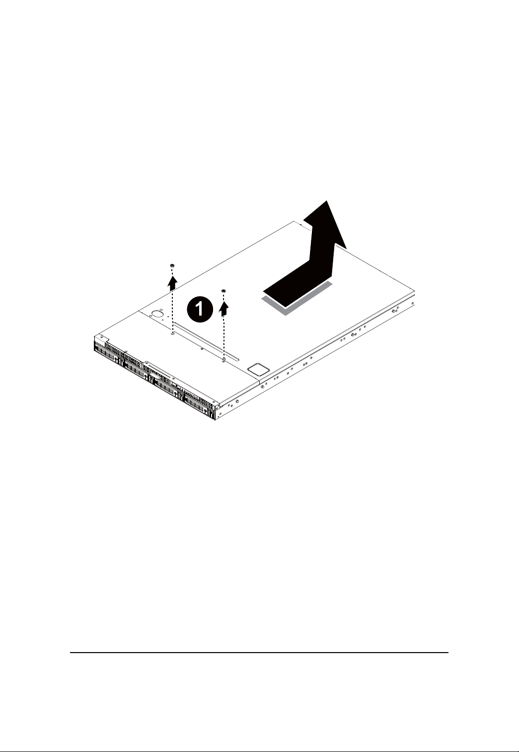
Remove the chassis cover.
Step 1 Loosen the screw on the front chassis cover.
Step 2 Push down the indentation located at the side of the back chassis.
Step 3 Slide toward the top chassis cover.
Step 4 Lift up to remove the top chassis cover.
12
Page 13
Hardware Installation Process
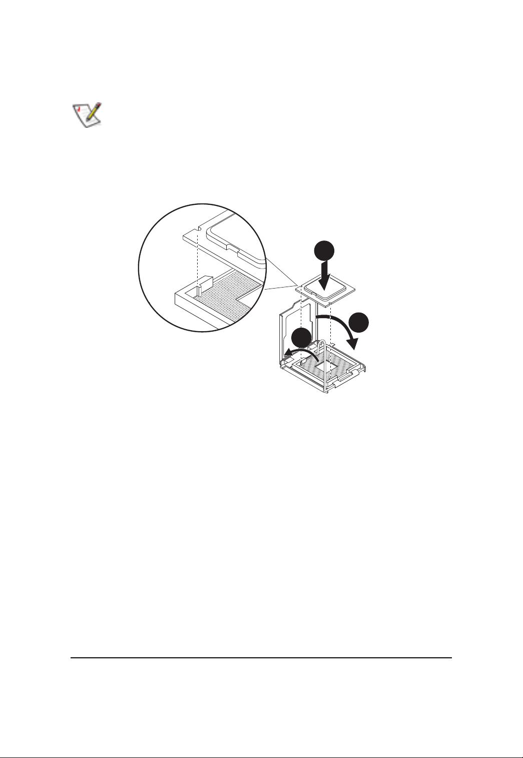
Installing the Processor
Please make sure the CPU type and speed that are supported by the motherboard.
Step 1 Raise the metal locking lever on the socket. Insert the CPU with the correct orientation.
Step 2 The CPU only fits in one orientation.
Step 3 Push the metal lever back into locked position.
1
2
3
13
Page 14
GS-R12T4H2-RH Rack Mount Server
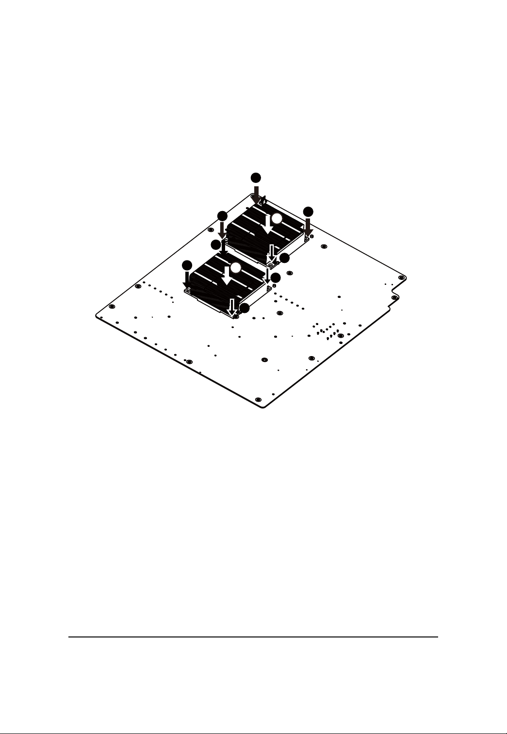
Installing the Heat Sink
Step 1 Place the Heat Sink on the CPU. Before putting the heat sink on the CPU, please well
remember to apply the thermal conductivity compound on the CPU.
Step 2 Seat the heat sink in the retention modules with the four screws. Installation completed.
3
5
3
5
1
1
2
1
1
4
4
2
14
Page 15
GS-R12T4H2-RH Rack Mount Server
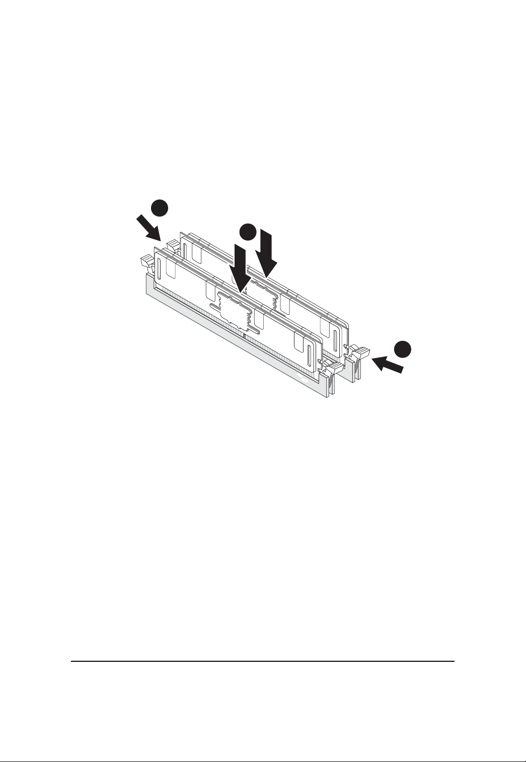
Installing the Memeory Module
Step 1. Insert the DIMM memory module vertically into the DIMM slot, and push it down.
Step 2. Close the plastic clip at both edges of the DIMM slots to lock the DIMM module.
NOTE! DIMM must be populated in order starting from DIMMA1/D1 sockets. For dualquad
channel operation, DIMMs must be installed in matched pairs.
Step 3. Reverse the installation steps when you wish to remove the DIMM module.
2
1
2
15
Page 16
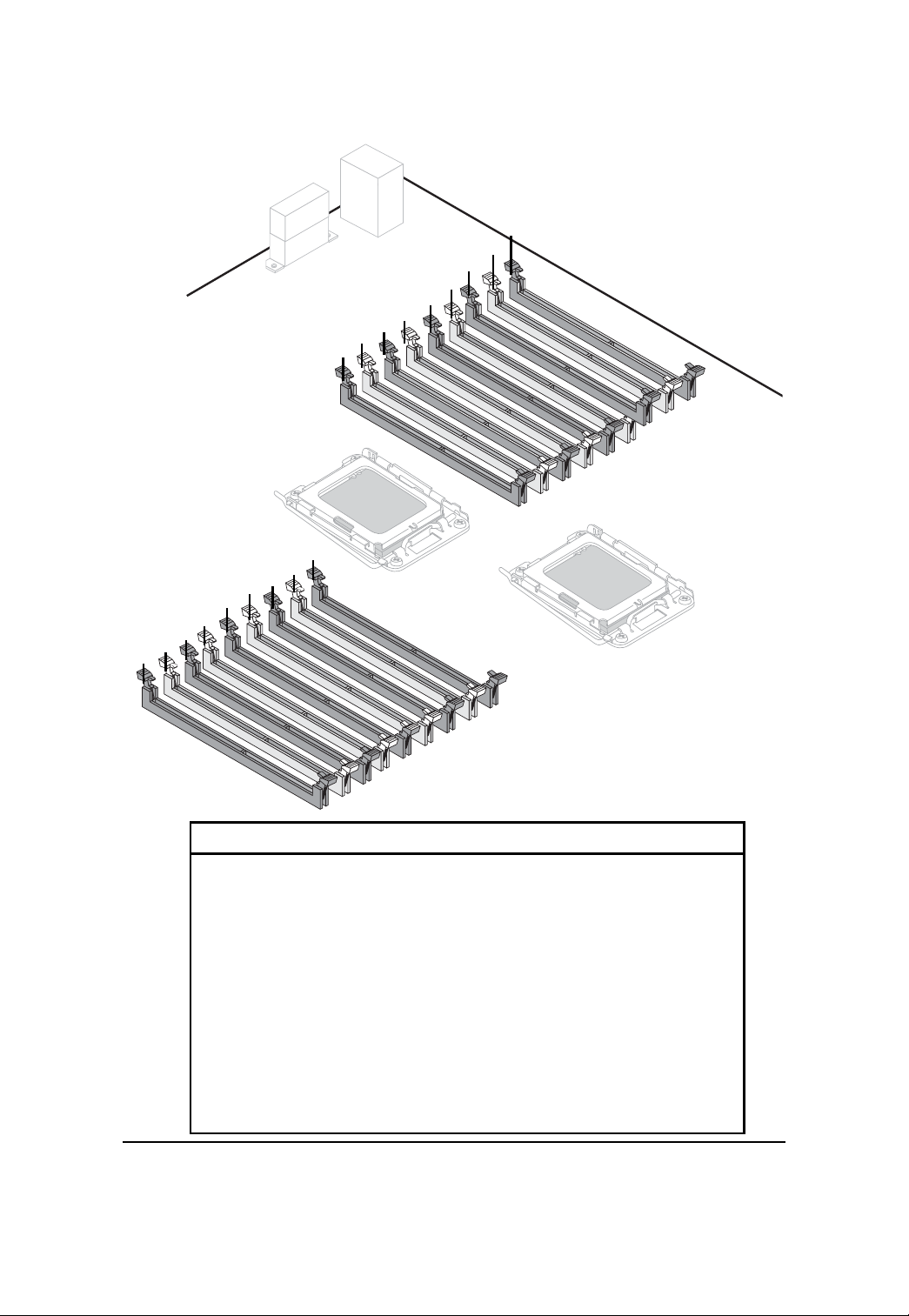
18
17
16
15
14
13
12
11
10
9
7
8
CPU2
Hardware Installation Process
1
2
3
4
5
6
CPU1
No. Code No. Code
1 DDR_P1C2D0 10 DDR_P0C0D2
2 DDR_P1C2D1 11 DDR_P0C0D1
3 DDR_P1C2D2 12 DDR_P0C0D0
4 DDR_P1C1D0 13 DDR_P0C1D2
5 DDR_P1C1D1 14 DDR_P0C1D1
6 DDR_P1C1D2 15 DDR_P0C1D0
7 DDR_P1C0D0 16 DDR_P0C2D2
8 DDR_P1C0D1 17 DDR_P0C2D1
9 DDR_P1C0D2 18 DDR_P0C2D0
16
Page 17
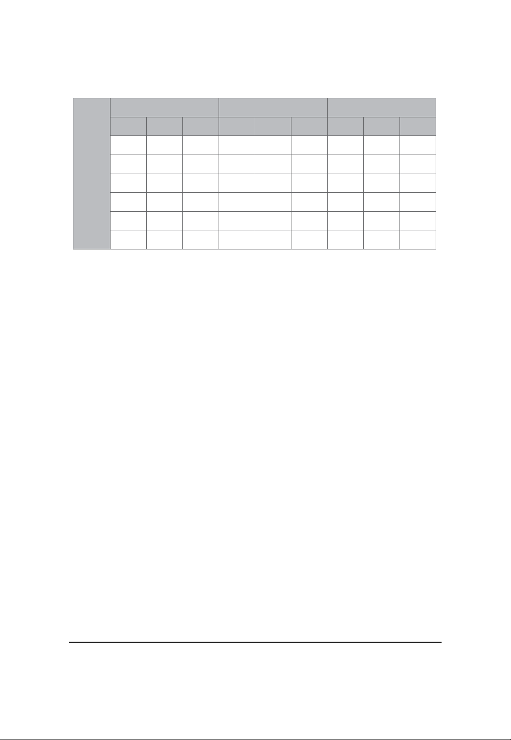
U-DIMM Population Table
Channel A Channel B Channel C
P0C0D0
P1C0D0
Single-Rank
P0C0D1
P1C0D1
xx
P0C0D2
P1C0D2
P0C1D0
P1C1D0
Single-Rank
P0C1D1
P1C1D1
P0C1D2
P1C1D2
xx
Hardware Installation Process
P0C2D0
P1C2D0
Single-Rank
P0C2D1
P1C2D1
P0C2D2
P1C2D2
xx
U-DIMM
Dual-Rank
Single-Rank Single-Rank
Single-Rank
Dual-Rank
x
Single-RankDual-Rank
Dual-Rank
Dual-Rank
x
Dual-Rank
Single-Rank Single-Rank
x
x
Single-Rank
x
Dual-Rank
x
x
Single-RankDual-Rank
Dual-Rank
Dual-Rank
x
Dual-Rank
Single-Rank Single-Rank
x
x
Single-Rank
x
Dual-Rank
x
x
Single-RankDual-Rank
Dual-Rank
Dual-Rank
x
x
x
x
x
17
Page 18

GS-R12T4H2-RH Rack Mount Server
R-DIMM Population Table
Channel A Channel B Channel C
P0C0D0
P1C0D0
Single-Rank
P0C0D1
P1C0D1
P0C0D2
P1C0D2
xx
P0C1D0
P1C1D0
Single-Rank
P0C1D1
P1C1D1
x
P0C1D2
P1C1D2
x
P0C2D0
P1C2D0
Single-Rank
P0C2D1
P1C2D1
P0C2D2
P1C2D2
xx
R-DIMM
Dual-Rank
Quad-Rank
Single-Rank Single-Rank
Dual-Rank
Single-Rank
Dual-Rank Dual-Rank
Quad-Rank
Quad-Rank
Quad-Rank
Single-Rank
Dual-Rank
Single-Rank
Single-Rank
Dual-Rank
Dual-Rank
Single-Rank
x
x
Single-Rank
Dual-Rank
Single-Rank
Dual-Rank
Single-Rank Single-Rank
Single-Rank Single-Rank
Dual-Rank
Single-Rank
Dual-Rank
Single-Rank
Dual-Rank
x
x
x
x
x
x
x
x
x
Single-Rank
Dual-Rank
Single-Rank
Dual-Rank
Dual-Rank
Dual-Rank
Quad-Rank
Single-Rank
Dual-Rank
Single-Rank
Dual-Rank
Quad-Rank
Quad-Rank
Quad-RankQuad-Rank
Single-Rank
Dual-Rank
Single-Rank
Single-Rank
Dual-Rank
Dual-Rank
Single-Rank
x
x
Single-Rank
Single-Rank
Dual-Rank
Dual-Rank
Single-Rank
Dual-Rank
Quad-Rank
Single-Rank
Single-Rank
Dual-Rank
Single-Rank
Dual-Rank
Single-Rank
Dual-Rank
x
x
x
x
x
x
x
x
x
Single-Rank
Single-Rank
Single-Rank
Dual-Rank
Single-Rank
Dual-Rank
Dual-Rank
Dual-Rank
Quad-Rank
Single-Rank Single-Rank
Dual-Rank
Single-Rank
Dual-Rank Dual-Rank
Quad-Rank
Quad-Rank
Quad-Rank Quad-Rank
Single-Rank
Dual-Rank
Single-Rank
Single-Rank
Dual-Rank
Dual-Rank
Single-Rank
x
x
Single-Rank
Dual-Rank
Single-Rank
Dual-Rank
Single-Rank Single-Rank
Single-Rank Single-Rank
Dual-Rank
Single-Rank
Dual-Rank
Single-Rank
Dual-Rank
x
x
x
x
x
x
x
x
x
Single-Rank
Dual-Rank
Single-Rank
Dual-Rank
Dual-Rank
Dual-Rank
Dual-Rank
Dual-Rank
Dual-Rank
Dual-Rank
18
Dual-Rank
Dual-Rank
Dual-Rank
Dual-Rank
Page 19
Hardware Installation Process
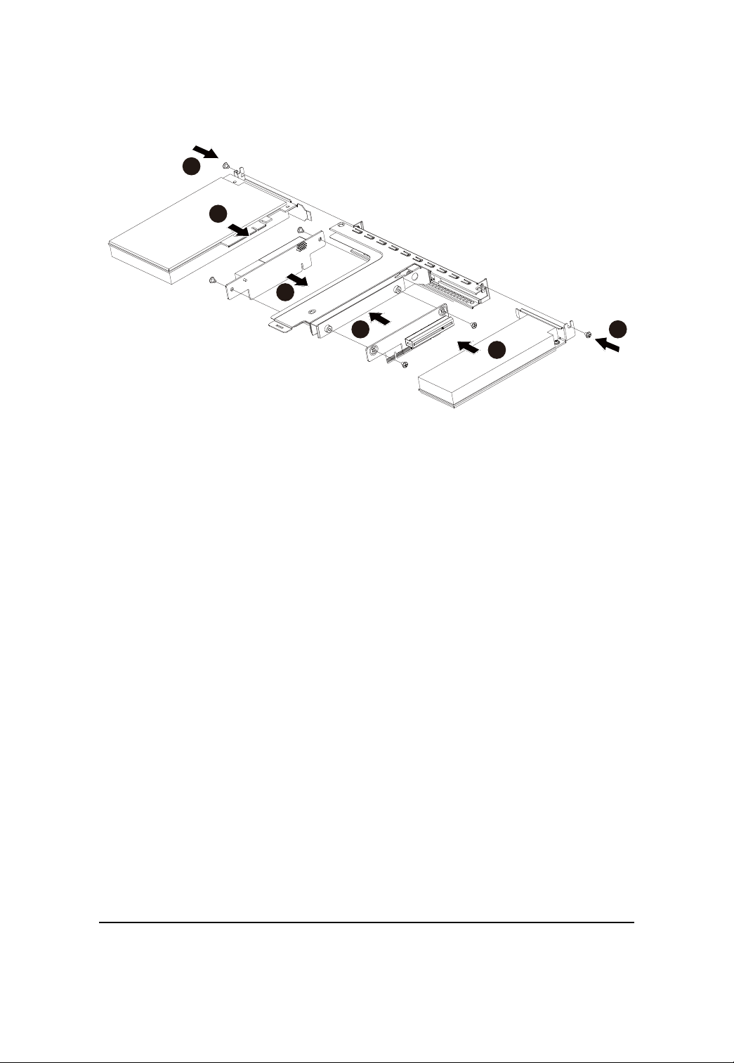
Installing the PCI Expansion Card
Step 1 Lift the riser bracket slightly, then pull it out from the server chassis.
Step 2 Loosen the riser bracket screws.
Step 3 Attach the mini card to the riser bracket and ecure the mini card with screws.
Step 4 Attach the mini card to the riser bracket the other side. Secure the mini card with screws.
Step 5 Slide the expansion card into the slot until the card firmly seats.
Step 6 Secure th expansion card with screws.
Step 7 Align the riser bracket to the system module.
2
2
19
1
Page 20
GS-R12T4H2-RH Rack Mount Server
6
5
4
3
6
5
20
Page 21
GS-R12T4H2-RH Rack Mount Server
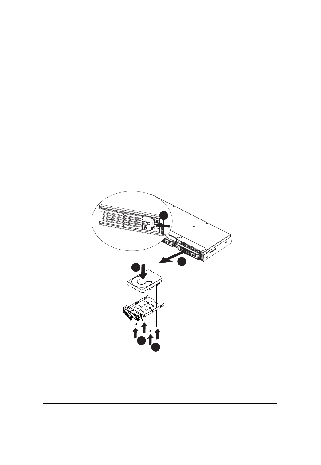
Installing the Hard Disk Drive
Step 1 Press the release button.
Step 2 Pull the locking lever to remove the HDD tray.
Step 3 Slide hard disk into blank.
Step 4 Secure the hard drive to the tray with four (4) screws as shown. Do not over tighten the
screws. Slide the blank into the bay until it locks into place.
Step 5 Engage the HDD Security Lock. For detail instruction, please see the following section.
Step 6 Connect cable and power.
1
3
2
4
4
21
Page 22
Hardware Installation Process
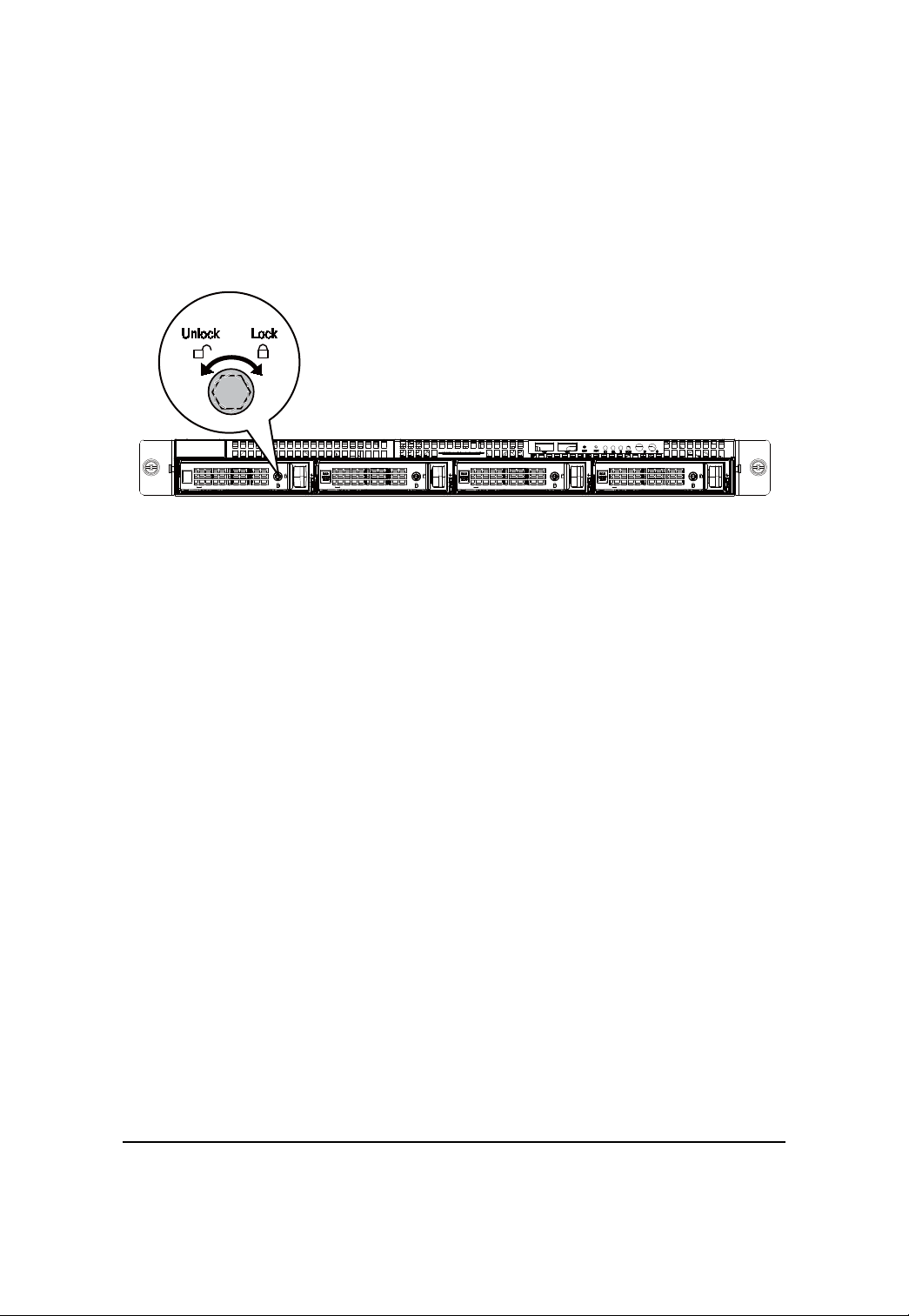
HDD Security Lock
The HDD bays incorporate a security screw to prevent accidental HDD release.
T o engage the lock, turn the security screw clock-wise toward the Lock symbol. To disengage the lock,
turn the security screw counter clock-wise toward the Unlock symbol as shown.
22
Page 23
GS-R12T4H2-RH Rack Mount Server
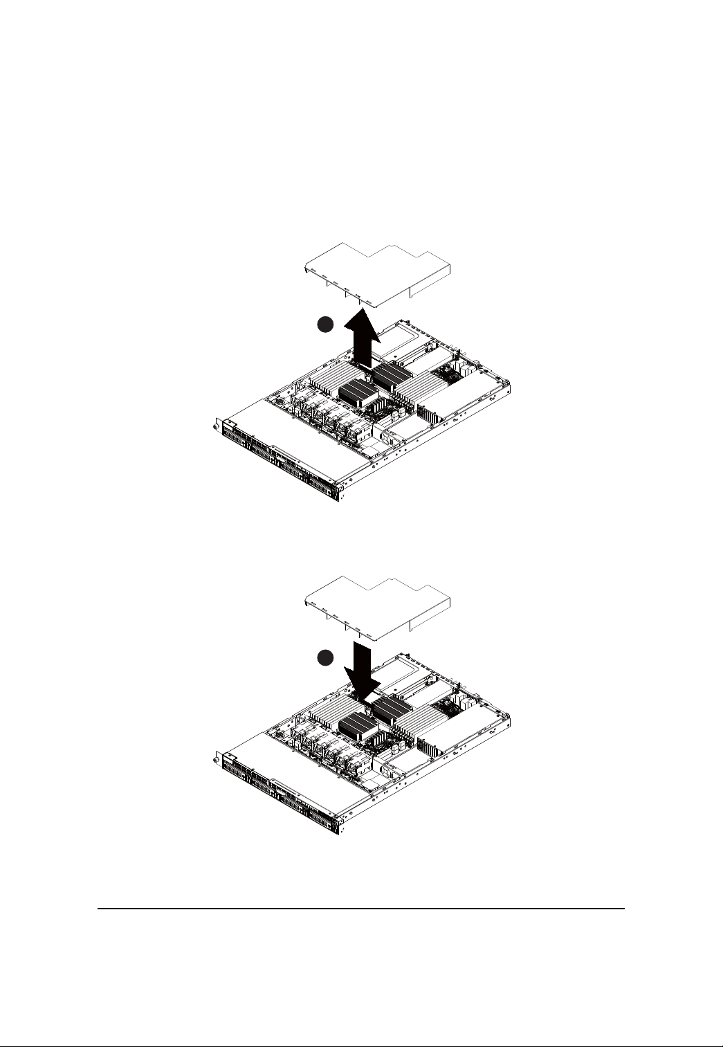
Installing and Replacing the F AN Duct
Step 1 Remove the airducts from the chassis by pulling the rear edge in the direction of the arrow
Step 2 With fan duct installation, align the fan duct with the guiding groove. Push down the fan duct
into chassis until its firmly seats.
1
0.3571
2
0.3571
23
Page 24
Hardware Installation Process
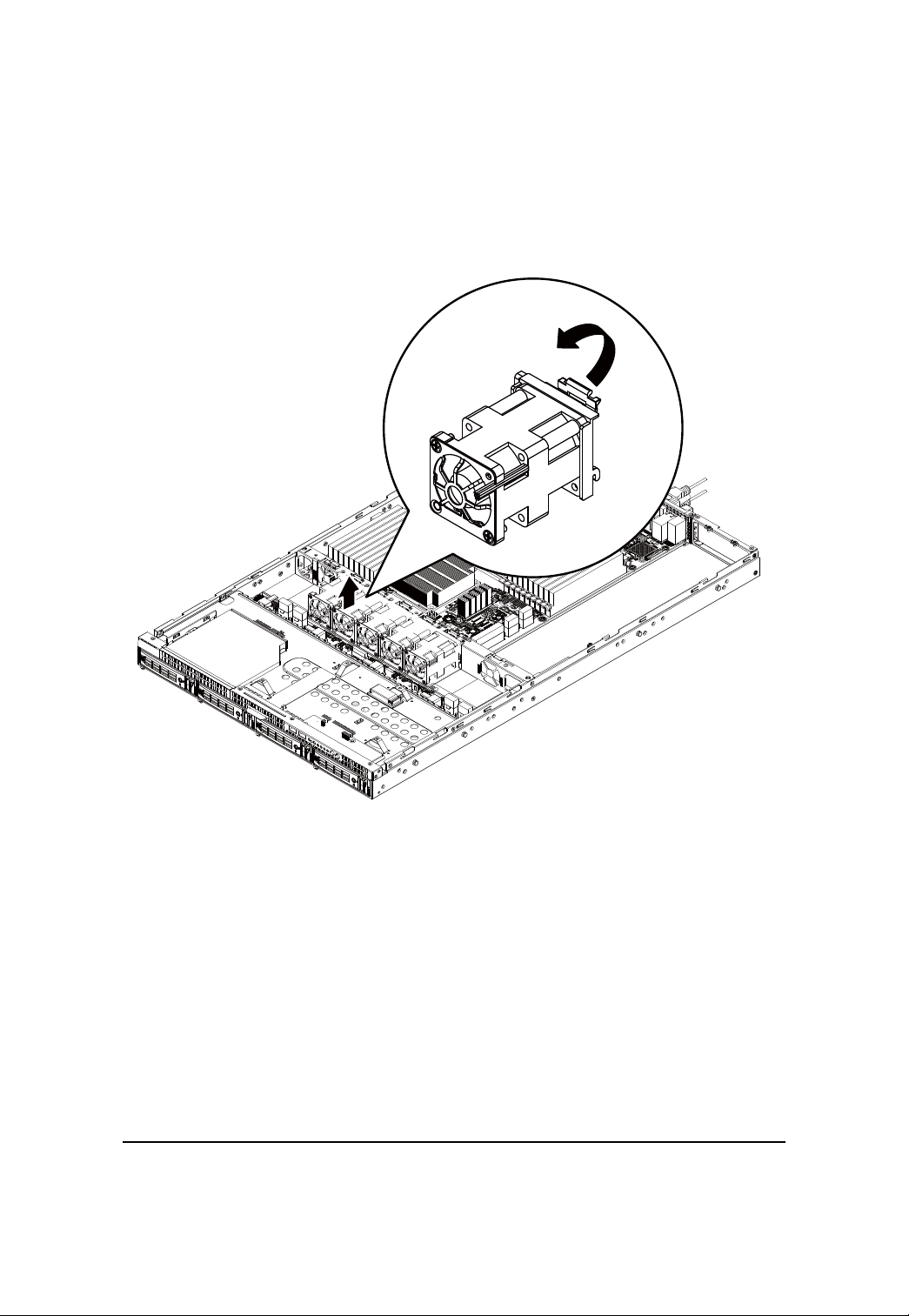
Replacing the F AN Assemblly
Step 1 Remove thefan assemble pulling the rear edge in the direction of the arrow
Step 2 Lift up the fan assembly from the chassis.
Step 3 Reverse the previous steps to install the replacement fan assembly.
24
Page 25
GS-R12T4H2-RH Rack Mount Server
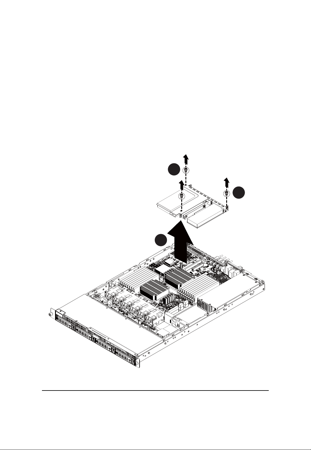
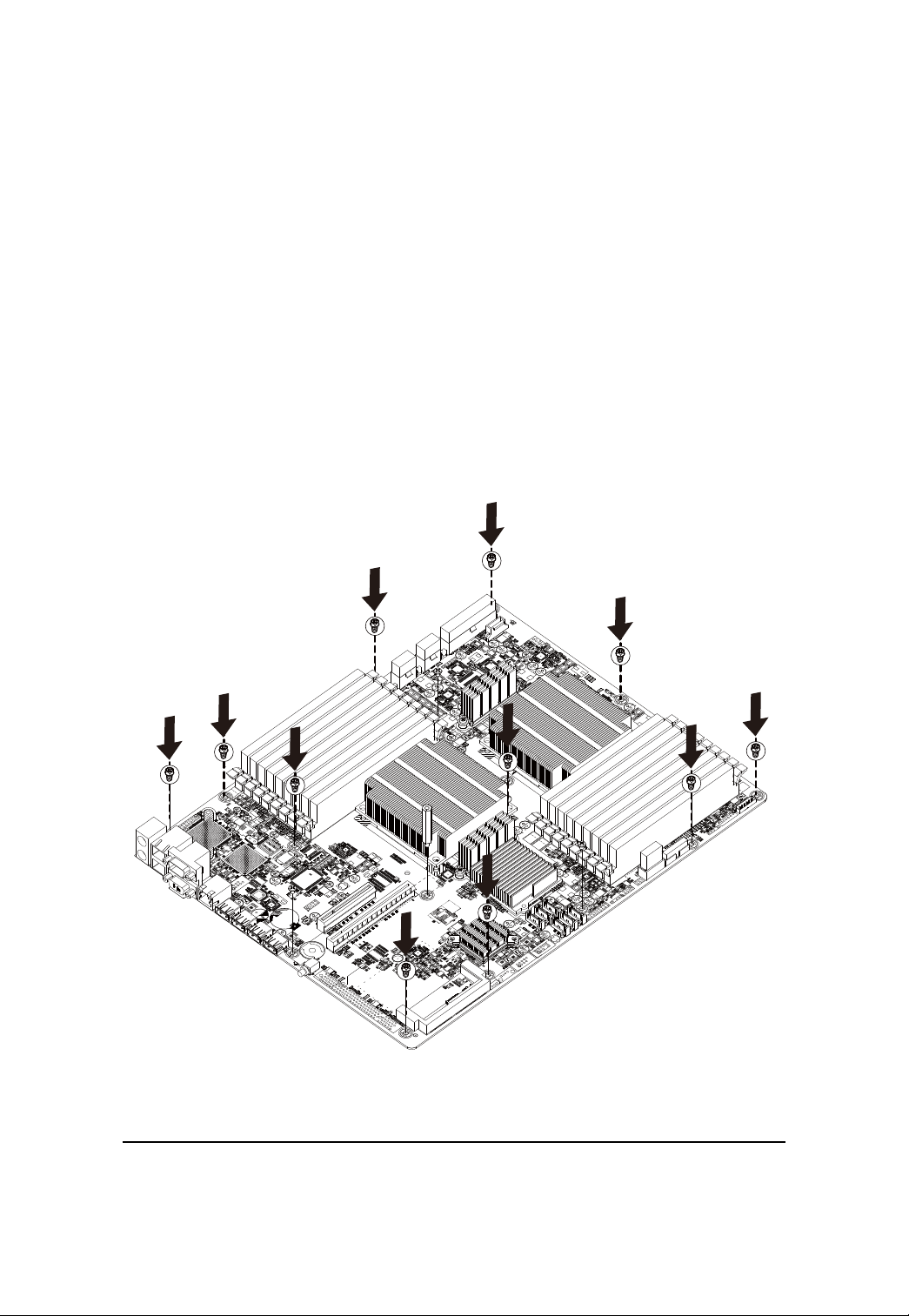
Replacing the Motherboard
Step 1 Remove the chassis cover. See Removing the Chassis Cover on page 12.
Step 2 Remove the fanduct from the chassis by pulling the rear edge in the direction of the arrow.
Step 3 Remove the processor, heat sink, memory module, and PCI assembly. See previous
sections for detail instruction.
Step 4 Disconnect the power, SA T A, front panel, and mainboard cable connectors. See Motherboard
Placement and Jumper Setting section on page 38.
Step 5 Remove the elevrn (11) screws securing the mainboard in place.
Step 6 Lift the mainboard out of the chassis in the direction of the arrow, front edge first, to clear the
I/O ports.
Step 7 Insert the replacement mainboard, rear edge first, to locate the I/O ports.
Step 8 Replace the elevrn (11) screws to secure the mainboard in place.
25
Page 26

Hardware Installation Process
Replacing the Power Supply
Step 1 Remove the fanduct from the chassis by pulling the rear edge.
Step 2 Disconnect the three power cables from the chassis as shown in the following image.
Step 3 Remove the thress screws securing the power supply to the chassis.
Step 4 Lift the power supply out of the chassis in the direction of the arrow.
Step 5 Insert the replacement power supply and replace the two securing screws.
Step 6 Connect the three power cables to the chassis as shown. Ensure that all the cables are flush
with the chassis and do not cause an obstruction.
26
Page 27

GS-R12T4H2-RH Rack Mount Server
27
Page 28

GS-R12T4H2-RH Rack Mount Server
Replacing the Chassis Cover
Step 1 Replace the cover, and slide the chassis in the direction of the arrow until the locking
button clicks into place.
Step 2 Tighten the securing screw on top of the server.until the locking button clicks into place.
28
Page 29

GS-R12T4H2-RH Rack Mount Server
Appearance of GS-R12T4H2-RH
Front View of GS-R12T4H2-RH
6 7
85
9
1 2
4
3
1. HDD bay Open to install a hard drive.
2. HDD bay lock Turn this to lock and unlock the HDD bay.
3. HDD front release button Slide this release to the right and pull out lever to remove
HDD bay.
4. HDD LED This LED shows HDD activity
5. ODD drive Place ODD device in this drive.
6. Front USB ports x2 Connect USB devices to these ports.
7. System LEDs System status LEDs.
9. ID Button Press to light front and rear ID LEDs.
9. Power Button Push the power button to turn the system on, and hold
down to turn the system off.
NOTE! For Front LED description, please go to Front Panel LED Indicators
section.
29
Page 30

Rear View of GS-R12T4H2-RH
System Appearance
1 2 3 4
5
3
6 7
8
9
1. Power Module Connect the power cable to the socket.
2. PS/2 port Connect the keyboard and mouse devices to this port.
3. GLAN port Connect a RJ-45 jack to this port to link to a 10/100/1000
Megabit Ethernet LAN.
4. Serial port Connect serial devices to this port.
5. VGA port Connect the monitor device to this port.
6. LAN port Connect a RJ-45 jack to this port to link to a 10/100 LAN.
This port is for server management.
7. USB port Connect USB devices to these four ports.
8. Low-profile riser card Remove this cover before installing a PCIE card.
9. Full-height riser card Remove this cover before installing a PCIE card.
30
Page 31

Front Panel LED Indicator
LED Description
4
5
6
23
1
No Indicator
1 Power
status
2 System ID
3 System
status
4 HDD
activity
Color State Description
Green On System has power applied to it
or ACPI S0 state
Green Blink System is in ACPI S1 state
(sleep mode)
N/A Off System is not powered on or in
ACPI S5 state (power off)
System is in ACPI S4 state
(hlbernate mode)
Blue On System identification is active
Off System identification is disabled
Green On Running or normal operation
Green Blink System degraded due to CPU or
DIMM error
Amber On Critical or non-recoverable
condition (Power module or
voltage power supply failure
or critical temperature)
Amber Blink Non-critical condition
N/A Off System not ready
May indicate the following:
POST error
NMI event
Processor or terminator
missing
Green Blink HDD access
N/A Off No access
31
Page 32

GS-R12T4H2-RH Rack Mount Server
No Indicator
5 LAN1
activity
6 LAN2
activity
Color State Description
Green On Link between system and
network or no access
Green Blink Network access
Green On Link between system and
network or no access
Green Blink Network access
32
Page 33

GS-R12T4H2-RH Rack Mount Server
LAN port LED Indicator
No Name
1 Speed
indicator
2 Link/activity
indicator
Color State Description
N/A Off 10Mbps connection
Green On 100Mbps connection
Orange On 1000Mbps connection
Note: The server management port does
not support 1000Mbps connection
Green On Active connection
Green Blink Transmit or receive connection
33
Page 34

Hard Disk Drive LED Description
LED Description
Description
HDD Prsent
HDD access
HDD failure
HDD removed
HDD connected and
rebuilding data
HDD locate
SAS/SATA HDD indicator
Green Red
On Off
Blink (4Hz) Off
Off On
Off On
On Blink (1 Hz)
Blink (4Hz) Blink (4Hz)
34
Page 35

GS-R12T4H2-RH Rack Mount Server
GC-BS14U-RH Back plane board Components
1113
15
17
18
19
2
20 21 22 2324 25 26 27
16
1214
9
10
7
8
5
6
3
4
No Code Description
1 P2 Power Connector (14-pin)
2 P1 Power Connector (14-pin)
3~14 SF1~SF12 System fan connectors #1~12
15 CD-ROM_PWR1 CD-ROM power connector
16 J3 CD-ROM power connector
17 J2 SMBUS connector from M/B to B/P
18 SGPIO_JP2 SGPIO connector from RAID card
19 SGPIO_JP1 SGPIO connector from Enclosure IC(Motherboard)
20~23 SA T A0~SA T A3 SA T A cable connectors #0~3
24~27 SAS0~SAS HDD connector #0~3 (SAS & SATA)
1
35
Page 36

GS-R12T4H2-RH Rack Mount Server
System Block Diagram
DDR3DDR3DDR3
DDR3DDR3DDR3
DDR3DDR3DDR3
Nehalem-EP
CPU1
Processor
LGA1366
Port 1
QPI
VRD 11.1VRD 11.1
CPU2
Nehalem-EP
Processor
LGA1366
Port 1
CH0
CH1
CH2
DDR3DDR3DDR3
DDR3DDR3DDR3
DDR3DDR3DDR3
PCIE x16
(x8 bandwidth)
PCIE X8
(x8 bandwidth)
SODIMM
(x4 bandwidth)
PCI slot (3.3V)
PCIE x8 GEN2
PCIE x8 GEN2
PCIE x4 GEN1
PCI
SATAII
QPI
INTEL
Tylersburg-24D
IOH
ESI
INTEL ICH10R
CLINK
USBX1 *2
USBX1 *2
QPI
PCIEx4
Kawela
RMI
ID
Switch
LPC
USB x 1 *2 (USB0/1)
PCIE x1
USBX1 *4
PILOT II
USB port x4
Front USB1
Front USB2
GLAN port x2
COM2
COM1
Rear VGA
BCM5221
RMII
ITE8720
KVM
LAN
PS/2
SATA1 SATA2 SATA3 SATA4 SATA5 SATA6
36
Page 37

GS-R12T4H2-RH Rack Mount Server
Connector Icon Description
Suggest Icon
Description
Keyboard
Mouse
VGA
COM
LAN
USB
37
Page 38

Motherboard Compononts
Motherboard Placement and Jumper Setting
GA-7TTSE-RH Motherboard Component
15
12
11
5
8
21
10
6
4
3
2
17
22
9
13
14
7
16
18
19
20
2324
1
38
Page 39

GS-R12T4H2-RH Rack Mount Server
Item Component
1. Processor 1 socket
2. Processor 2 socket
3. SATA data cable cable connectors
4. USB connector for internal USB (Tape device)
5. CMOS battery
6. 3-pin IPMB connector
7. LPT_DEBUG connector
8. Serial port connector
9. HDD back plance borad connector
10. Front panel connector
11. SO-DIMM I/F
12. PCI 32/33 MHz slot
13. PCI- E x12 slot
14. PCI- E x8 slot
15. Rear I/O ports
16. DDR3 DIMM slots x 9 for secondary processor
17. DDR3 DIMM slots x 9 for primary processor
18. 8-pin Power connector for primary processor
19. 8-pin Power connector for secondary processor
20. 24-pin Power connector
21. SGPIO connector 1 for ICH10R
22. SGPIO connector 2 for RAID card
23. System fan connector 1 for back plance board
24. System fan connector 2 for back plance board
39
Page 40

Jumper Setting
1
2
3
4
Jumper Setting
6
7
5
1 ) BIOS_RVCR1 (BIOS Revocery jumper)
1
1
1-2 close: Normal operation. (Default setting)
2-3 close: Enable BIOS Recovery function.
2 ) CLR_CMOS1 (Clear CMOS jumper)
Y ou may clear the CMOS data to its default values by this jumper.
Default value doesn’t include the “Shunter” to prevent from improper use this jumper. To
clear CMOS, temporarily short 2-3 pin.
1
1
1-2 close: Normal operation (Default setting)
2-3 close: Clear CMOS
40
Page 41

GS-R12T4H2-RH Rack Mount Server
3 ) CLR_RTC1 (Clear RTC jumper)
1
1
1-2 close: Normal operation. (Default setting)
2-3 close: Clear RTC status
4 ) ME_ENABLE (BMC Selection jumper)
1
1
1-2 Close: Normal operation. (Default setting)
2-3 Close: Enable BMC function.
5 ) PASS_DIS1 (Skip Supervisor password jumper)
1
1
1-2 Close: Normal operation. (Default setting)
2-3 Close: Clear Supervisor Password in BIOS setup menu.
6/7 ) JP_STRAP2/ JP_STRAP8 (PilotII firmware upgrade jumper)
JP_STRAP2 JP_STRAP8 Descripeion
1
1
1
1
Boot from BMC BOOT SPI Interface. (Default setting)
Boot From BMC LPC BOOT ROM interface.
1
1
1
1
Boot From internal ROM(Scratchpad Registers)
Boot From internal ROM(Scratchpad Registers)
41
Page 42

Jumper Setting
Expansion Card Components Description
The two riser cards installed in the PCI riser card bracket assembly povides support for both fullheoght and low-profile expansion cards.
Full height and low profile PCI Express riser cards
1
2
No. Code Description
1 PCI-E_X16_1 Full-height riser slot
2 PCI-E_2 Low-profile riser slot
42
Page 43

GS-R12T4H2-RH Rack Mount Server
BIOS Setup
BIOS (Basic Input and Output System) includes a CMOS SETUP utility which allows user to
configure required settings or to activate certain system features.
The CMOS SETUP saves the configuration in the CMOS SRAM of the motherboard.
When the power is turned off, the battery on the motherboard supplies the necessary power to the
CMOS SRAM.
ENTERING SETUP
When the power is turned on, press the <F2> button during the BIOS POST (Power-On Self Test)
will take you to the CMOS SETUP screen. You can enter the BIOS setup screen by pressing
"Ctrl + F1".
CONTROL KEYS
<> Move to previous item
<> Move to next item
<> Move to the item in the left hand
<> Move to the item in the right hand
<Esc> Main Menu - Quit and not save changes into CMOS Status Page Setup Menu and
Option Page Setup Menu - Exit current page and return to Main Menu
<+/PgUp> Increase the numeric value or make changes
<-/PgDn> Decrease the numeric value or make changes
<F1> General help, only for Status Page Setup Menu and Option Page Setup Menu
<F2> Reserved
<F3> Reserved
<F4> Reserved
<F6> Reserved
<F7> Reserved
<F8> Reserved
<F9> Load the Optimized Defaults
<F10> Save all the CMOS changes, only for Main Menu
43
Page 44

GETTING HELP
Main Menu
The on-line description of the highlighted setup function is displayed at the bottom of the screen.
Status Page Setup Menu / Option Page Setup Menu
Press F1 to pop up a small help window that describes the appropriate keys to use and the
possible selections for the highlighted item. T o exit the Help Window press <Esc>.
Select the Load Setup Defaults item in the BIOS Exit Setup menu when somehow
the system is not stable as usual. This action makes the system reset to the default
settings for stability.
Main
This setup page includes all the items in standard compatible BIOS.
Advanced
This setup page includes all the items of Phoenix BIOS special enhanced features.
(ex: Auto detect fan and temperature status, automatically configure hard disk parameters.)
Power
This setup page includes all the items of Green function features.
Security
Change, set, or disable password. It allows you to limit access the system and setup.
Server
Server additional features enabled/disabled setup menus.
Boot
This setup page include all the items of first boot function features.
Exit
There are five optionsin this selection: Exit Saving Changes, Exit Discarding Changes, Load
Optimal Defaults, Load Failsafe Defaults, and Discard Changes.
BIOS Setup
44
Page 45

GS-R12T4H2-RH Rack Mount Server
Main
Once you enter Phoenix BIOS Setup Utility, the Main Menu (Figure 1) will appear on the screen. Use
arrow keys to select among the items and press <Enter> to accept or enter the sub-menu.
Figure 1: Main
System Date
Set the System Date. Note that the “Day” automatically changed after you set the date.
System Ti me
The time is calculated based on the 24-hour military time clock. Set the System Time
(HH:MM:SS)
BIOS Informa ntion
BIOS Version: displays the BIOS version.
BIOS Date: displays the BIOS established date.
Processor Information
This category includes the information of CPU type, Speed ,and number of CPU count.
45
Page 46

T otal Memory
The BIOS determines how much total memory is present during the POST.
BIOS Setup
46
Page 47

Advanced
About This Section: Advanced
With this section, allowing user to configure your system for advanced operation. User can
set the Processor configuration, Memory configuration, Advanced chipset configuration, PCI
configuration , SAT A configuration, I/O device configuration, Boot configuration, and Thermal and
acoustic configuration.
BIOS Setup
Figure 2: Advanced
47
Page 48

GS-R12T4H2-RH Rack Mount Server
Processor Configuration
48
Page 49

BIOS Setup
Processor Configuration
This category includes the Processor information of CPU Speed, Processor ID ,Processor
L2 / L3 Cache, and QPI Frequency. And setup sub-menu for CPU Power Management.
Please note that setup menu options will be variable depends on the type of CPU.
Multiproce ssor Spe cification
This option allows user to configure the multiprocessor(MP) specification revision level.
Some operating system will require 1.1 for compatibility reasons.
1.4 Support MPS Version 1.4 . (Default setting)
1.1 Support M PS Version 1.1.
Intel (R) Virtualization T echnology
Intel(R) Virtualization T echnology will allow a platform to run multiple operating systems and
applications in independent partitions. With virtualization, one computer system can function as
multiple “virtual” systems. With processor and I/O enhancements to Intel’s various platforms,
Intel Virtualization T echnology can improve the performance and robustness of today’s softwareonly virtual machine solutions.
Enabled Enable Intel Virtualization T echnology . (Default setting)
Disabled Disable this function.
Execute Disable Bit
Enabled Enable Execute Disable Bit. (Default setting)
Disabled Disable this function.
NUMA Aware
Enabled Enable NUMA Aware. (Default setting)
Disabled Disable NUMA Aware.
ACPI SRA T Report
Enabled Enable ACPI SRA T Report. (Default setting)
Disabled Disable ACPI SRAT Report.
Active Processor Cores
Options One Core, Two cores, Max Cores. Default setting is Max Cores.
A20M Support
Enabled Enable A20M Support. (Default setting)
Disabled Disable A20M Support.
49
Page 50

GS-R12T4H2-RH Rack Mount Server
Machine Checking
Enabled Enable Machine Checking. (Default setting)
Disabled Disable Machine Checking.
Fast String Operations
Enabled Enable Fast String Operations. (Default setting)
Disabled Disable Fast String Operations.
Set Max Ext CPUID=3
Enabled Enable Set Max Ext CPUID=3.
Disabled Disable Set Max Ext CPUID=3. (Default setting)
Echo TPR
Enabled Enable Echo TPR.
Disabled Disable Echo TPR.(Default setting)
Discrete MTRR Allocation
Enabled Enable Discrete MTRR Allocation.
Disabled Disable Discrete MTRR Allocation. (Default setting)
Thermal Ma nagement
Enabled Enable Thermal Management. (Default setting)
Disabled Disable Thermal Management.
50
Page 51

GS-R12T4H2-RH Rack Mount Server
Processor Power Management
Figure 2-1-1: Processor Power Management
EIST (G V3) & C State
Enabled Enable EIST (GV3) and C State items. (Default setting)
Disabled Disable EIST (GV3) and C State items.
EIST (G V3)
Enabled Enable EIST (GV3. (Default setting)
Disabled Disable EIST (GV3).
EIST PSD Function
HW_ALL In HW_ALL mode, the rpocessor hardware is responsible for coordinating
the P-state among logical processors dependencies. The OS is responsible
for keeping the P-state request up to date on all logical processors.
(Default setting)
51
Page 52

BIOS Setup
SW_ALL In SW_ALL mode, the OS Power Manager is responsible for coordinating
the P-state among loical processors with dependencies and must initiate the
transition on all of those Logical Processors.
SW_ANY In SW_ANY mode, the OS Power Manager is responsible for corrdinating
the P-state among logical processors with dependencies and may initiate
the transition on any of those Logical Processors .
Turbo Mode
Turbo Mode automatically allows processor cores to run faster than marked frequency if the
physical processor is operating below power, temperature and current specification limits.
Turbo Mode can be engaged with SMT (Simultanceous Multi Threading) enabled and 1 to 4 cores
active and is not limited to only a single core or logical processor.
Enabled Turbo Mode. (Default setting)
Disabled Disable Turbo Mode.
T State
Enabled Enable CPU T-State. (Default setting)
Disabled Disable T-State.
CPU C State
Enabled Enable ACPI C-State (C0, C1/C1E, C3, C6 and C7). (Default setting)
Disabled Disable C-State.
CPU C1E
Enabled Enable CPU C1E. (Default setting)
Disabled Disable CPU C1E.
OS ACPI C3 Re port
C3 Desire state for the Nehalem core C3 state include in the CST as ACPI C3
state. (Default setting)
C2 Desire state for the Nehalem core C2 state include in the CST as ACPI C2
state.
Disabled Disable OS ACPI C3 Report.
CPU C6 Report
Enabled Desire state for the Nehalem core C6 state include in the CST as ACPI C3
52
Page 53

GS-R12T4H2-RH Rack Mount Server
state. (Default setting)
Disabled Disable CPU C6 Report.
CPU C7 Report
Enabled Desire state for the Nehalem core C7 state include in the CST as ACPI C3
state. (Default setting)
Disabled Disable CPU C7 Report.
Package C State Li mit
Desired state for the C-State package limit.
Options C0, C1 State, C3 State, C6 State, C7 State, No Limit. The default setting
is No Limit.
ACPI MW AIT extensions
Enabled CST using MWAIT extension isenabled for OSPM use. (Default setting)
Disabled Disable ACPI MWAIT extensions.
53
Page 54

Memory Configuration
BIOS Setup
54
Page 55

GS-R12T4H2-RH Rack Mount Server
Memory Information
These following items display all information of current Base Memory, Extended Memory,
, and installed DIMM Status. These items are display-only which is determined by POST
(Power On Self Test) of the BIOS.
Memory Control Settings
Manual Select ‘Manual” will pops up sub-menu for configuration.
Auto Auto configuration. (Default setting)
Memory RAS Mode
Identify the Memory RAS mode.
Memory Frequency
Select the desire value of Memory frequency. Options available: Auto, DDR-3 800,
DDR-3 1066, and DDR-3 1333.
Cha nge Interleave setting
Change the interleave setting. Options available: 1-way, 2-way, 3-way, 4-way, and 6-way.
Rank Interleave setting
Configure interleave setting. Options available: 1-way, 2-way, and 4-way.
55
Page 56

Advanced Chipset Configuration
BIOS Setup
56
Page 57

GS-R12T4H2-RH Rack Mount Server
Figure 2-3-1: Intel VT for Directed I/O (VT-d)
57
Page 58

BIOS Setup
Intel VT for Dir ected I/O (VT -d)
Enabled Intel VT for Directed I/O (VT-d). (Default setting)
Disabled Disable Intel VT for Directed I/O (VT -d).
Interrupt Remapping
Enabled Enable Interrupt Remapping. (Default setting)
Disabled Disable Interrupt Remapping.
Coherency Support
Enabled Enable Coherency Support.
Disabled Disable Coherency Support. (Default setting)
ATS
Enabled Enable ATS. (Default setting)
Disabled Disable ATS.
PassThrough DMA
Enabled Enable PassThrough DMA. (Default setting)
Disabled Disable PassThrough DMA.
VT -d for Por t1~Port 10
Enabled Enable VT-d support for Port 1~Port 10 ports through A TSR structures in
ACPI T ables. (Default setting)
Disabled Disable VT -d for Port1~Port 10.
Adva nced Chipset Control Main Menu Options
Course Grain Clocking Gating
Enabled Enable Course Grain Clocking Gating.
Disabled Disable Course Grain Clocking Gating. (Default setting)
Intel (R) I/OA T
Enabled Enable configuration mapped accesses to the I/OAT configuration sapce.
(Default setting)
Disabled Disable I/OAT.
4GB PCI HoleGranularity
Select the granularity of PCI hole for PCI resource. If MTRRS are not enough, we may use
this option to reduce the MTRR occupation.
512MB Select 512MB as granularity of PCI hole.
1GB Select 1GB as granularity of PCI hole. (Default setting)
58
Page 59

GS-R12T4H2-RH Rack Mount Server
2GB Select 2GB as granularity of PCI hole.
QPI Control Settings
Enabled Enable QPI Control settings. (Default setting)
Disabled QPI Control settings.
QPI Link Fast Mode
Enabled Enable QPI Link Fast Mode. (Default setting)
Disabled Disable QPI Link Fast Mode.
QPI Frequency Selection
Identify the desire value of QPI frequency. Option available: Auto, 4.800GT, 5.866GT.
Default setting is Auto.
QPI Isoch Support
Enabled Enable QPI Isoch Support.
Disabled Disable QPI Isoch Support. (Default setting)
QPI DCA Support
Enabled Enable QPI DCA Support. (Default setting)
Disabled Disable QPI DCA Support.
QPI scramble selection
Enabled Enable QPI scramble selection.
Disabled Disable QPI scramble selection. (Default setting)
QPI Error Report
Enabled Enable QPI Error Report.
Disabled Disable QPI Error Report. (Default setting)
Memory ECC Error Log
Identify the the memory ecc error log. Option available: Disable, Correctable Error,
Uncorrectable Error, and Both. The default setting is Both.
ECC Threshold
Use the “+” and “-” keys to adjust the desire value of ECC Threshold.
Enable Multi media Timer
Yes Enable Multimedia Timer support. (Default setting)
No Disable this function.
59
Page 60

PCI Configuration
Onboard LAN iSCSI Boot ROM
Enabled Enable Onboard LAN iSCSI Boot ROM.
Disabled Disable this function. (Defualt setting)
Onboard LAN1 Control
Enabled Enable Onboard LAN controller. (Defualt setting)
Disabled Disable this function.
LAN1Option ROM
Enabled Enable onboard LAN1 device and initialize device expansion
Disabled Disable this function.
Onboard LAN2 Control
Enabled Enable Onboard LAN controller. (Defualt setting)
Disabled Disable this function.
BIOS Setup
Figure 2-4: PCI Configuration
ROM. (Default setting)
60
Page 61

GS-R12T4H2-RH Rack Mount Server
LAN2Option ROM
Enabled Enable onboard LAN2 device and initialize device expansion
ROM. (Default setting)
Disabled Disable this function.
Legacy USB Support
This option allows user to function support for legacy USB.
Enabled Enables support for legacy USB (Default setting)
Disabled Disables support for legacy USB.
61
Page 62

GS-R12T4H2-RH Rack Mount Server
SA TA Configuration
Figure 2-5: SATA Configuration
62
Page 63

Serial A T A
Enabled Enables on-board serial AT A function. (Default setting)
Disabled Disables on-board serial A T A function.
Native Mode Operation
This option allows user to set the native mode for Serial A TA function.
Auto Auto detected. (Default setting)
Serial AT A Set Native mode to Serial ATA.
SATA Controller Mode Option
Compatible Mode SAT A and P A TA drives are auto-detected and placed in
Legacy mode.
Enhanced Mode SA T A and PA TA drives are auto-detected and placed in
Native mode. (Default setting)
Note: Pre-Win2000 operating system do not work in Enhanced mode.
SATA RAID Enable
Enabled Enabled SA T A RAID function.
Disabled Disable this function. (Default setting)
SATA AHCI Enable
Enabled Set this item to enable SATA AHCI function for WinXP-SP1+IAA
driver supports AHCI mode.
Disabled Disabled this function. (Default setting)
BIOS Setup
SATA Port 0/1/2/3/4/5
The category identifies the types of Serial SATA hard disk from drive 0 to 5 that has been
installed in the computer. System will automatically detect HDD type.
Note that the specifications of your drive must match with the drive table. The hard disk will not
work properly if you enter improper information for this category.
Hard drive information should be labled on the outside device casing. Enter the appropriate option
based on this information.
TYPE
1-39: Predefined types.
Users: Set parameters by User.
63
Page 64

BIOS Setup
Auto: Set parameters automatically. (Default setting)
CD-ROM: Use for ATAPI CD-ROM drives or double click [Auto] to set all HDD parameters
automatically.
ATAPI Removable: Removable disk drive is installed here.
Multi-Sector Transfer
This field displays the information of Multi-Sector Transfer Mode.
Disabled: The data transfer from and to the device occurs one sector at a time.
Auto: The data transfer from and to the device occurs multiple sectors at a time if the device
supports it.
LBA Mode Control This field shows if the device type in the specific IDE channel
support LBA Mode.
32-Bit I/O Enable this function to max imize the IDE data transfer rate.
Transfer Mode This field shows the information of T eansfer Mode.
Ultra DMA Mode This filed displays the DMA mode of the device in the specific IDE
channel.
64
Page 65

I/O DeviceConfiguration
Figure 2-6: I/O Device Configuration
Serial Port A
This allows users to configure serial prot A by using this option.
Enabled Enable the configuration. (Default setting)
Disabled Disable the configuration.
BIOS Setup
Base I/O Address/IRQ
3F8/IRQ4 Set IO address to 3F8/IRQ4.(Default setting)
2F8/IRQ3 Set IO address to 2F8/IRQ3.
3E8/IRQ7 Set IO address to 3E8/IRQ7.
2E8/IRQ5 Set IO address to 2E8/IRQ5.
Serial Port B
This allows users to configure serial prot B by using this option.
Enabled Enable the configuration (Default setting)
Disabled Disable the configuration.
65
Page 66

GS-R12T4H2-RH Rack Mount Server
Base I/O Address/IRQ
3F8/IRQ4 Set IO address to 3F8/IRQ4.
2F8/IRQ3 Set IO address to 2F8/IRQ3. (Default setting)
3E8/IRQ7 Set IO address to 3E8/IRQ7.
2E8/IRQ5 Set IO address to 2E8/IRQ5.
66
Page 67

Boot DeviceConfiguration
BIOS Setup
Figure 2-7: Boot Configuration
Boot -time Di agnostic Screen
When this item is enabled, system will shows Diagnostic status when system boot.
Enabled Enable Boot-time Diagnostic screen.
Disabled Disable this function. (Default setting)
Post Error Pause
The category determines whether the computer will stop if an error is detected during power up.
All Error Whenever the BIOS detects a non-fatal error the system will be
stopped.
No Error The system boot will not stop for any error that may be detected
and you will be prompted.
All, But Keyboard The system boot will not stop for a keyboard error; it will stop for all
other errors. (Default setting)
67
Page 68

GS-R12T4H2-RH Rack Mount Server
NumLock
This option allows user to select power-on state for NumLock.
On Enable NumLock. (Default setting)
Off Disable this function.
68
Page 69

Thermal and Acoustic Configuration
Figure 2-8: Thermal and Acoustic Configuration
Open loop Thermal Throttle
Enabled Open loop Thermal Throttle. (Default setting)
BIOS Setup
Disabled Disable Open loop Thermal Throttle.
T emperature Chassis inlet
This item is user defined. Use nuber key to adjust desired value.
T emperatur e Rise
This item is user defined. Use nuber key to adjust desired value.
Air speed to the DIMM s
This item is user defined. Use nuber key to adjust desired value.
System Altitude
This item is user defined. Use nuber key to adjust desired value.
Pitch between DIMM s
This item is user defined. Use nuber key to adjust desired value.
69
Page 70

GS-R12T4H2-RH Rack Mount Server
Close loop Thermal Throttle
Enabled Close loop Thermal Throttle. (Default setting)
Disabled Disable Close loop Thermal Throttle.
T e mperatur e hystere sis
This item is user defined. Use nuber key to adjust desired value.
T emperature guardba nd
This item is user defined. Use nuber key to adjust desired value.
T emperature Chassis inlet
This item is user defined. Use nuber key to adjust desired value.
T emperatur e Rise
This item is user defined. Use nuber key to adjust desired value.
Air speed to the DIMM s
This item is user defined. Use nuber key to adjust desired value.
System Altitude
This item is user defined. Use nuber key to adjust desired value.
Pitch between DIMM s
This item is user defined. Use nuber key to adjust desired value.
70
Page 71

GS-R12T4H2-RH Rack Mount Server
Power
Figure 3: Power
After Power Failure
This option provides user to set the mode of operation if an AC / power loss occurs.
Power On System power state when AC cord is re-plugged.
Stay Off Do not power on system when AC power is back.
Last State Set system to the last sate when AC power is removed. Do not power on
system when AC power is back. (Default setting)
71
Page 72

Security
About This Section: Security
In this section, user can set either supervisor or user passwords, or both for different level of
password securities. In addition, user also can set the virus protection for boot sector.
BIOS Setup
Figure 4: Security
Set Supervisor Password
Y ou can install and change this options for the setup menus. T ype the password up to 6
characters in lengh and press <Enter>. The password typed now will clear any previously
entered password from the CMOS memory. You will be asked to confirm the entered
password. T ype the password again and press <Enter>. You may also press <Esc> to abort
the selection and not enter a specified password or press <Enter> key to disable this option.
72
Page 73

GS-R12T4H2-RH Rack Mount Server
Set User Password
Y ou can only enter but do not have the right to change the options of the setup menus. When
you select this function, the following message will appear at the center of the screen to assist
you in creating a password.
Type the password up to 6 characters in lengh and press <Enter>. The password typed now
will clear any previously entered password from the CMOS memory. You will be asked to
confirm the entered password. Type the password again and press <Enter>. You may also
press <Esc> to abort the selection and not enter a specified password.
Password on boot
Password entering will be required when system on boot.
Enabled Requries entering password when system on boot.
Disabled Disable this function. (Default setting)
73
Page 74

Server
BIOS Setup
Figure 5: Server
74
Page 75

GS-R12T4H2-RH Rack Mount Server
System Management
75
Page 76

BIOS Setup
System Ma nagement
This category allows user to view the system management features. Including information of
Motherboard Hardware information and software information.
BMC IP Addr ess Source
Address obtained by BMC running DHCP or Static address.
Option available: DHCP, Static.
76
Page 77

GS-R12T4H2-RH Rack Mount Server
Console Redirection
Figure 5-2: Console Redirection
Console Redirection
If this option is set to enabled, it will use a port on the motherboard to run console redirection
function.
On-board COM A Use Serial Port A as the COM port address.
On-board COM B Use Serial Port B as the COM port address.
Disabled Disable this function. (Default setting)
Flow Control
This option provide user to enable the flow control function.
None Not supported.
XON/XOFF Software control.
CTS/RTS Hardware control. (Default setting)
Baud Rate
77
Page 78

This option allows user to set the specified baud rate.
Options 300, 1200, 2400, 9600, 19.2K, 38.4K, 57.6K, 115.2K.
T erminal Type
This option allows user to select the specified terminal type. This is defined by IEEE.
Options VT100, VT100 8bit, PC-ANSI 7bit, PC-ANSI, VT100+, VT -UTF8,
ASCII.
Continue C.R. after POST
This option allows user to enable console redirection after O.S has loaded.
On Enable console redirection after O.S has loaded.
Off Disable this function. (Default setting)
BIOS Setup
78
Page 79

GS-R12T4H2-RH Rack Mount Server
Boot
Figure 6: Boot
Boot Priority Order
This field determines which type of device the system attempt to boot from after
PhoenixBIOS Post completed. Specifies the boot sequence from the available devices. If
the first device is not a bootable device, the system will seek for next available device.
Key used to view or configure devices:
Up and Down arrows select a device.
<+> and <-> moves the device up or down.
<f> and <r> specifies the device fixed or removable.
<x> exclude or include the device to boot.
<Shift + 1> Enable or disable a device.
<1-4> Loads default boot secquence.
79
Page 80

Exit
Figure 7: Exit
About This Section: Exit
Once you have changed all of the set values in the BIOS setup, you should save your
changes and exit BIOS setup program. Select “Exit” from the menu bar, to display the
following sub-menu.
Exit Saving Cha nges
This option allows user to exit system setup with saving the changes.
Press <Enter> on this item to ask for the following confirmation message:
Pressing ‘Y’ to store all the present setting values tha user made in this time into CMOS.
Therefore, whenyou boot up your computer next time, the BIOS will
re-configure your system according data in CMOS.
Exit Discarding Changes
This option allows user to exit system setup without changing anyprevious settings values in
CMOS. The previous selection remain in effect.
This will exit the Setup Utility and restart your compuetr when selecting this option.
BIOS Setup
80
Page 81

GS-R12T4H2-RH Rack Mount Server
Loa d Settup Default
if you highlight this item and press Enter, a dialog box asks if you want to install optimal
settings for all the items in the Setup utility. Press the Y key to indicate Yes, and then press
Enter to install the optimal settings.
Discard Change s
Select this item and press Enter to discard any changes you have made without leaving the
setup utility.
Save Change s
This option allows user to save setup dat ato CMOS.
Press [Yes] to save setup data to CMOS.
81
 Loading...