

Page 1

GA-Z87X-OC
User's Manual
Rev. 1002
12ME-Z87XOC-1002R
Page 2
Apr. 12, 2013
Motherboard
GA-Z87X-OC
Apr. 12, 2013
Motherboard
GA-Z87X-OC
Page 3
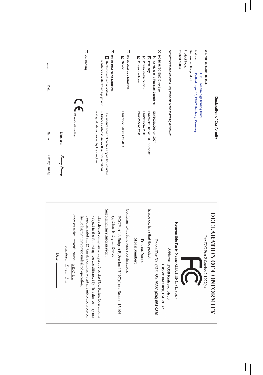
Copyright
© 2013 GIGA-BYTE TECHNOLOGY CO., LTD. All rights reserved.
The trademarks mentioned in this manual are legally registered to their respective owners.
Disclaimer
Information in this manual is protected by copyright laws and is the property of GIGABYTE.
Changes to the specications and features in this manual may be made by GIGABYTE
without prior notice.
No part of this manual may be reproduced, copied, translated, transmitted, or published in any
form or by any means without GIGABYTE's prior written permission.
Documentation Classications
In order to assist in the use of this product, GIGABYTE provides the following types of
documentations:
For quick set-up of the product, read the Quick Installation Guide included with the product.
For detailed product information, carefully read the User's Manual.
For product-related information, check on our website at: http://www.gigabyte.com
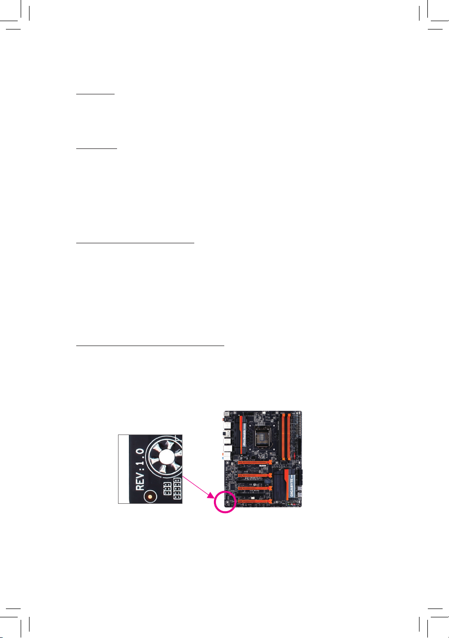
Identifying Your Motherboard Revision
The revision number on your motherboard looks like this: "REV: X.X." For example, "REV:
1.0" means the revision of the motherboard is 1.0. Check your motherboard revision before
updating motherboard BIOS, drivers, or when looking for technical information.
Example:
Page 4

Table of Contents
Box Contents ...................................................................................................................6
Optional Items .................................................................................................................6
GA-Z87X-OC Motherboard Layout ..................................................................................7
GA-Z87X-OC Motherboard Block Diagram .....................................................................8
Chapter 1 Hardware Installation .....................................................................................9
1-1 Installation Precautions .................................................................................... 9
1-2 ProductSpecications .................................................................................... 10
1-3 Installing the CPU and CPU Cooler ............................................................... 13
1-3-1 Installing the CPU ...................................................................................................13
1-3-2 Installing the CPU Cooler .......................................................................................15
1-4 Installing the Memory ..................................................................................... 16
1-4-1 DualChannelMemoryConguration .....................................................................16
1-4-2 Installing a Memory ................................................................................................17
1-5 Installing Expansion Cards ............................................................................. 18
1-6 Setting up AMD CrossFire™/NVIDIA® SLI™Conguration .............................. 19
1-7 Back Panel Connectors .................................................................................. 21
1-8 Onboard Buttons, Switches, and LEDs .......................................................... 23
1-9 Internal Connectors ........................................................................................ 26
Chapter 2 BIOS Setup .................................................................................................. 37
2-1 Startup Screen ............................................................................................... 38
2-2 The Main Menu .............................................................................................. 39
2-3 M.I.T. .............................................................................................................. 41
2-4 System ........................................................................................................... 52
2-5 BIOS Features ............................................................................................... 53
2-6 Peripherals ..................................................................................................... 56
2-7 Power Management ....................................................................................... 60
2-8 Save & Exit ..................................................................................................... 62
- 4 -
Page 5

Chapter3 ConguringSATAHardDrive(s) ...................................................................63
3-1 ConguringSATAControllers ......................................................................... 63
3-2 Installing the SATA RAID/AHCI Driver and Operating System ....................... 75
Chapter 4 Drivers Installation ........................................................................................79
4-1 Chipset Drivers ............................................................................................... 79
4-2 Application Software ...................................................................................... 80
4-3 Information ..................................................................................................... 80
Chapter 5 Unique Features ...........................................................................................81
5-1 BIOS Update Utilities ..................................................................................... 81
5-1-1 Updating the BIOS with the Q-Flash Utility .............................................................81
5-1-2 Updating the BIOS with the @BIOS Utility .............................................................84
5-2 APP Center .................................................................................................... 85
5-2-1 EasyTune................................................................................................................86
5-2-2 EZ Setup .................................................................................................................87
5-2-3 ON/OFF Charge2 ...................................................................................................92
5-2-4 USB Blocker ...........................................................................................................93
Chapter 6 Appendix ...................................................................................................... 95
6-1 ConguringAudioInputandOutput ............................................................... 95
6-1-1 Conguring2/4/5.1/7.1-ChannelAudio ...................................................................95
6-1-2 ConguringS/PDIFIn/Out ......................................................................................97
6-1-3 ConguringMicrophoneRecording ........................................................................99
6-1-4 Using the Sound Recorder ...................................................................................101
6-2 Troubleshooting............................................................................................ 102
6-2-1 Frequently Asked Questions ................................................................................102
6-2-2 Troubleshooting Procedure ..................................................................................103
6-3 Debug LED Codes ....................................................................................... 105
Regulatory Statements ............................................................................................ 109
Contact Us ...............................................................................................................111
- 5 -
Page 6

Box Contents
5 GA-Z87X-OC motherboard
5 Motherboard driver disk
5 User's Manual
5 Quick Installation Guide
5 Four SATA cables
5 I/O Shield
5 One 2-Way SLI bridge connector
5 One 2-Way CrossFire bridge connector
5 Twelve voltage measurement cables
5 One OC Brace
The box contents above are for reference only and the actual items shall depend on the product package you
obtain. The box contents are subject to change without notice.
Optional Items
2-portUSB2.0bracket(PartNo.12CR1-1UB030-6*R)
eSATAbracket(PartNo.12CF1-3SATPW-4*R)
3.5"FrontPanelwith2USB3.0/2.0ports(PartNo.12CR1-FPX582-2*R)
S/PDIFIncable(PartNo.12CR1-1SPDIN-1*R)
HDMI-to-DVIadapter(PartNo.12CT2-HDMI01-1*R)
COMportcable(PartNo.12CF1-1CM001-3*R)
- 6 -
Page 7
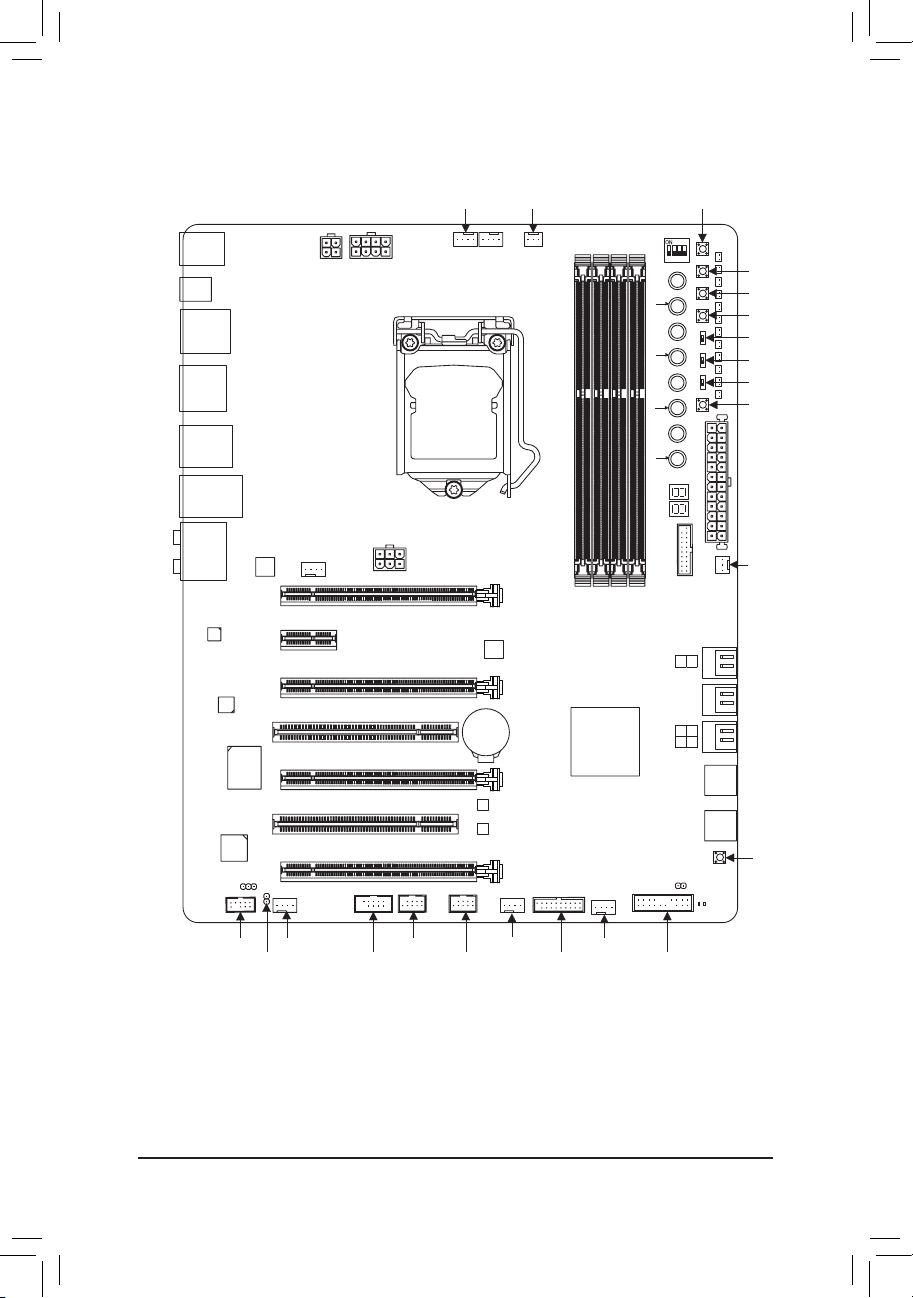
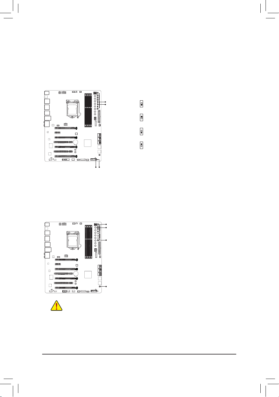
GA-Z87X-OC Motherboard Layout
R_USB
OC_IGNITION
HDMI
R_USB30_2
DP_HDMI_SPDIF
KB_MS_USB3
USB30_LAN
Renesas®
uPD720210
AUDIO
®
Intel
GbE LAN
CODEC
iTE®Super I/O
PCIe to PCI
Bridge
SPDIF_IN
F_AUDIO
SPDIF_O
ATX_12V
SYS_FAN1
PCIEX1_1
PCIEX4_1
PCI1
PCIEX8
PCI2
PCIEX4_2
SYS_FAN2
ATX_12V_2X4
OC_PEG
GA-Z87X-OC
F_USB2
COMA
CPU_FAN
LGA1150
PCIEX16
CPU_OPT
Renesas®
uPD720210
BAT
B_BIOS
M_BIOS
SYS_FAN3
SYS_FAN6
F_USB30_2F_USB1
DDR3_2
DDR3_4
Intel® Z87
SYS_FAN4
PCIE_SW
RATIO_DW
FREQ_DW
GEAR
TAG
DDR3_3
DDR3_1
CLR_CMOS
F_PANEL
RST_SW
DIP
123 4
PW_SW
_
+
RATIO_UP
_
+
FREQ_UP
TURBO
(Note
Debug LED
F_USB30_1
1
0
SATA 3
5 3
4 2
F_USB4
F_USB3
MEM_SAFE
DTB
SET_LOCK
SB
BIOS_SW
TGR
CMOS_SW
ATX
SYS_FAN5
CBAT_SW
MBIOS_LED
BBIOS_LED
(Note) Fordebugcodeinformation,pleaserefertoChapter6.
- 7 -
Page 8
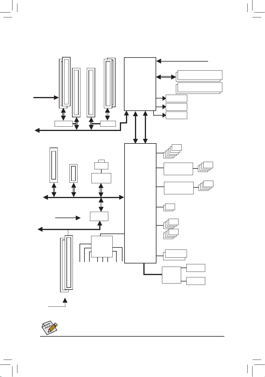
GA-Z87X-OC Motherboard Block Diagram
2 PCI Express x4
PCIe CLK
(100MHz)
x8
Switch
PCI Express Bus
1 PCI Express x4
1 PCI Express x1
x4
PCI Express Bus
PCIe CLK
(100MHz)
PCI Bus
2 PCI Express x8
1 PCI Express x8
x8
x1
PCIe to PCI
1 PCI Express x16
x16
x16
Switch
LAN
RJ45
Intel® GbE
LAN
x1
x1
Bridge
LGA1150
CPU
DMI 2.0
Intel® Z87
FDI
CPUCLK+/-(100MHz)
DDR31600/1333MHz
Dual Channel Memory
DisplayPort
HDMI
HDMI
6 SATA 6Gb/s
Renesas®
uPD720210 Hub
4 USB 3.0/2.0
Renesas®
uPD720210 Hub
4 USB 3.0/2.0
2 USB 3.0/2.0
8 USB 2.0/1.1
CODEC
Dual BIOS
MIC
Line In
Line Out
Side Speaker Out
2 PCI
PCI CLK
(33MHz)
Fordetailedproductinformation/limitation(s),referto"1-2ProductSpecications."
Rear Speaker Out
Center/Subwoofer Speaker Out
S/PDIF In
S/PDIF Out
- 8 -
LPC Bus
iTE®
Super I/O
COM
PS/2 KB/Mouse
Page 9

Hardware Installation
Chapter 1 Hardware Installation
1-1 Installation Precautions
The motherboard contains numerous delicate electronic circuits and components which can become
damaged as a result of electrostatic discharge (ESD). Prior to installation, carefully read the user's
manual and follow these procedures:
• Prior to installation, make sure the chassis is suitable for the motherboard.
• Prior to installation, do not remove or break motherboard S/N (Serial Number) sticker or
warranty sticker provided by your dealer. These stickers are required for warranty validation.
• Always remove the AC power by unplugging the power cord from the power outlet before
installing or removing the motherboard or other hardware components.
• When connecting hardware components to the internal connectors on the motherboard, make
sure they are connected tightly and securely.
• When handling the motherboard, avoid touching any metal leads or connectors.
• It is best to wear an electrostatic discharge (ESD) wrist strap when handling electronic
components such as a motherboard, CPU or memory. If you do not have an ESD wrist strap,
keep your hands dry and rst touch a metal object to eliminate static electricity.
• Prior to installing the motherboard, please have it on top of an antistatic pad or within an
electrostatic shielding container.
• Before unplugging the power supply cable from the motherboard, make sure the power supply
has been turned off.
• Before turning on the power, make sure the power supply voltage has been set according to
the local voltage standard.
• Before using the product, please verify that all cables and power connectors of your hardware
components are connected.
• To prevent damage to the motherboard, do not allow screws to come in contact with the
motherboard circuit or its components.
• Make sure there are no leftover screws or metal components placed on the motherboard or
within the computer casing.
• Do not place the computer system on an uneven surface.
• Do not place the computer system in a high-temperature environment.
• Turning on the computer power during the installation process can lead to damage to system
components as well as physical harm to the user.
• If you are uncertain about any installation steps or have a problem related to the use of the
product, please consult a certied computer technician.
- 9 -
Page 10
Hardware Installation
1-2 ProductSpecications
CPU Support for Intel® Core™ i7 processors/Intel® Core™ i5 processors/
Intel® Core™ i3 processors/Intel® Pentium® processors/
Intel® Celeron® processors in the LGA1150 package
(Go to GIGABYTE's website for the latest CPU support list.)
L3 cache varies with CPU
Chipset Intel® Z87 Express Chipset
Memory 4 x 1.5V DDR3 DIMM sockets supporting up to 32 GB of system memory
* Due to a Windows 32-bit operating system limitation, when more than 4 GB of
physical memory is installed, the actual memory size displayed will be less than
the size of the physical memory installed.
Dual channel memory architecture
Support for DDR3 1600/1333 MHz memory modules
Support for non-ECC memory modules
Support for Extreme Memory Profile (XMP) memory modules
(Go to GIGABYTE's website for the latest supported memory speeds and
memory modules.)
Onboard
Graphics
Integrated Graphics Processor:
- 2 x HDMI ports, supporting a maximum resolution of 4096x2160
* Support for HDMI 1.4a version.
- 1 x DisplayPort port, supporting a maximum resolution of 3840x2160
* Support for DisplayPort 1.2 version.
- Maximum shared memory of 1 GB
Audio Realtek® ALC892 codec
High Definition Audio
2/4/5.1/7.1-channel
Support for S/PDIF In
Support for S/PDIF Out
LAN Intel® GbE LAN chip (10/100/1000 Mbit)
Expansion Slots 1 x PCI Express x16 slot, running at x16 (PCIEX16)
* For optimum performance, if only one expansion card is to be installed, be sure to
1 x PCI Express x16 slot, running at x8 (PCIEX8)
* The PCIEX8 slot shares bandwidth with the PCIEX16 slot. It will operate at up to x8
2 x PCI Express x16 slots, running at x4 (PCIEX4_1, PCIEX4_2)
* The PCIEX4_1 slot shares bandwidth with the PCIEX16 and PCIEX8 slots. When
* When installing a x8 or above card in the PCIEX4_1 slot, make sure to set PCIE Slot
(The PCIEX16, PCIEX8, and PCIEX4_1 slots conform to PCI Express 3.0
1 x PCI Express x1 slot
install it in the PCIEX16 slot.
mode when the PCIEX16 is populated.
it is populated, the PCIEX16 slot will operate at up to x8 mode and the PCIEX8 slot
will operate at up to x4 mode.
Conguration in BIOS Setup to x4. (Refer to Chapter 2, "BIOS Setup," "Peripherals,"
for more information.)
standard.)
(The PCIEX4_2 and PCIEX1_1 slots conform to PCI Express 2.0 standard.)
2 x PCI slots
- 10 -
Page 11
Hardware Installation
Multi-Graphics
Technology
Storage Interface Chipset:
USB Chipset:
Internal
Connectors
Sup port for 4-Way/3-Way/2- Way AMD CrossFir e™/2-Wa y NVIDIA® SLI™
Technology
- 6 x SATA 6Gb/s connectors (SATA3 0~5) supporting up to 6 SATA 6Gb/s
devices
- Support for RAID 0, RAID 1, RAID 5, and RAID 10
- Up to 2 USB 3.0/2.0 ports (available through the internal USB header)
- Up to 8 USB 2.0/1.1 ports (2 ports on the back panel, 2 ports onboard, 4
ports available through the internal USB headers)
Chipset + 2 Renesas® uPD720210 USB 3.0 Hubs:
- Up to 8 USB 3.0/2.0 ports (6 ports on the back panel, 2 ports available
through the internal USB header)
1 x 24-pin ATX main power connector
1 x 8-pin ATX 12V power connector
1 x 4-pin ATX 12V power connector
1 x OC PEG power connector
6 x SATA 6Gb/s connectors
1 x CPU fan header
water cooling fan header (CPU_OPT)
1 x
6 x system fan headers
1 x front panel header
1 x front panel audio header
1 x S/PDIF Out header
1 x S/PDIF In header
2 x USB 3.0/2.0 headers
2 x USB 2.0/1.1 headers
2 x USB 2.0/1.1 ports
1 x serial port header
1 x Clear CMOS jumper
1 x power button
1 x reset button
1 x Clear CMOS button
1 x Gear button
1 x OC Turbo button
1 x OC Tag button
1 x CPU BCLK Down button
1 x CPU BCLK Up button
1 x CPU Ratio Down button
1 x CPU Ratio Up button
1 x Memory Safe button
1 x Settings Lock button
1 x Direct to BIOS button
1 x OC Trigger switch
1 x OC PCIe switch
1 x Clear Battery button
2 x BIOS switches
1 x onboard voltage measurement module
- 11 -
Page 12

Hardware Installation
Back Panel
Connectors
2 x USB 2.0/1.1 ports
1 x OC Ignition button
6 x USB 3.0/2.0 ports
1 x optical S/PDIF Out connector
2 x HDMI ports
1 x DisplayPort
1 x PS/2 keyboard/mouse port
1 x RJ-45 port
6 x audio jacks (Center/Subwoofer Speaker Out/Rear Speaker Out/Side
Speaker Out/Line In/Line Out/Microphone)
I/O Controller iTE I/O Controller Chip
Hardware
Monitor
System voltage detection
CPU/System/Chipset temperature detection
CPU/CPU OPT/System fan speed detection
CPU/System overheating warning
CPU/CPU OPT/System fan fail warning
CPU/CPU OPT/System fan speed control
* Whether the fan speed control function is supported will depend on the cooler you
install.
BIOS 2 x 128 Mbit flash
Use of licensed AMI EFI BIOS
Support for DualBIOS
PnP 1.0a, DMI 2.0, SM BIOS 2.6, ACPI 2.0a
Unique Features Support for Q-Flash
Support for Xpress Install
Support for APP Center
* Available applications in APP Center may differ by motherboard model. Supported
functions of each application may also differ depending on motherboard
specications.
- @BIOS
- EasyTune
- EZ Setup
- ON/OFF Charge2
- USB Blocker
Bundled
Software
Norton Internet Security (OEM version)
Intel® Rapid Start Technology
Intel® Smart Connect Technology
Intel® Smart Response Technology
cFosSpeed
™
- 12 -
Page 13
Hardware Installation
Operating
System
Support for Windows 8/7
Form Factor ATX Form Factor; 30.5cm x 24.4cm
* GIGABYTE reserves the right to make any changes to the product specications and product-related information without
prior notice.
* Please visit the Support&Downloads\Utility page on GIGABYTE's website to check the supported operating system(s)
for the software listed in the "Unique Features" and "Bundled Software" columns.
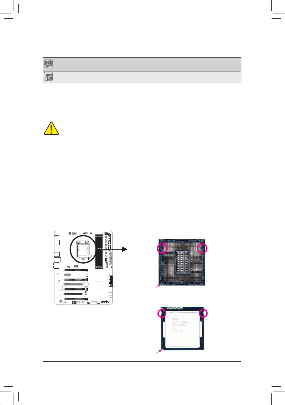
1-3 InstallingtheCPUandCPUCooler
Read the following guidelines before you begin to install the CPU:
• Make sure that the motherboard supports the CPU.
(Go to GIGABYTE's website for the latest CPU support list.)
• Always turn off the computer and unplug the power cord from the power outlet before installing the
CPU to prevent hardware damage.
• Locate the pin one of the CPU. The CPU cannot be inserted if oriented incorrectly. (Or you may
locate the notches on both sides of the CPU and alignment keys on the CPU socket.)
• Apply an even and thin layer of thermal grease on the surface of the CPU.
• Do not turn on the computer if the CPU cooler is not installed, otherwise overheating and damage
of the CPU may occur.
• Set the CPU host frequency in accordance with the CPU specications. It is not recommended
that the system bus frequency be set beyond hardware specications since it does not meet the
standard requirements for the peripherals. If you wish to set the frequency beyond the standard
specications, please do so according to your hardware specications including the CPU, graphics
card, memory, hard drive, etc.
1-3-1 InstallingtheCPU
A. Locate the alignment keys on the motherboard CPU socket and the notches on the CPU.
DIP
4
123
Alignment
Key
LGA1150 CPU Socket
Alignment
Key
Pin One Corner of the CPU Socket
LGA1150 CPU
Notch
Triangle Pin One Marking on the CPU
- 13 -
Notch
Page 14
Hardware Installation
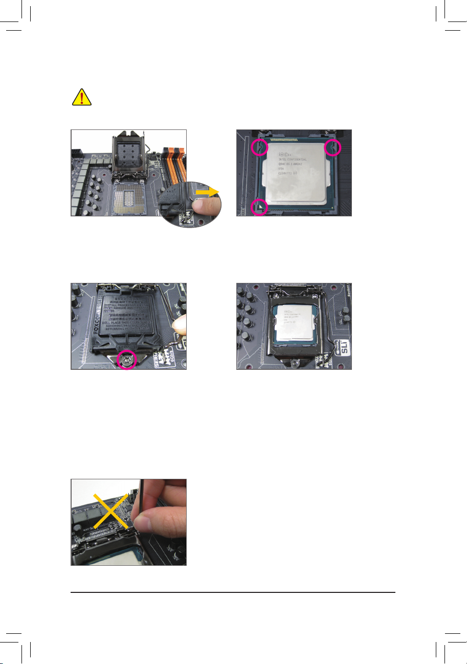
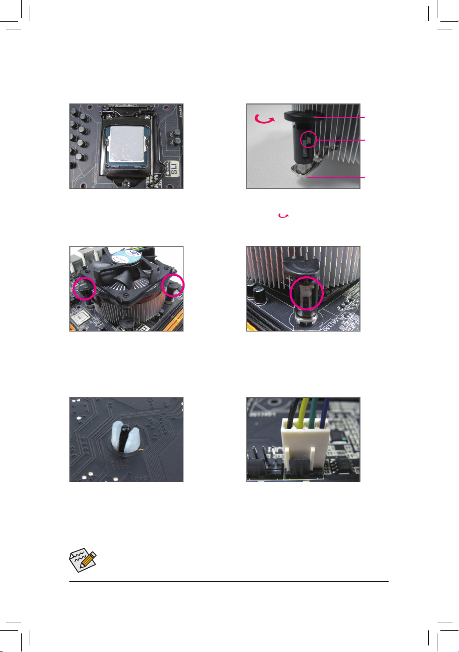
B. Follow the steps below to correctly install the CPU into the motherboard CPU socket.
• Before installing the CPU, make sure to turn off the computer and unplug the power cord from
the power outlet to prevent damage to the CPU.
• To protect the socket contacts, do not remove the protective plastic cover unless the CPU is
inserted into the CPU socket. Save the cover properly and replace it if the CPU is removed.
Step 1:
Gently press the CPU socket lever handle down
and away from the socket with your nger. Then
completely lift the CPU socket lever and the metal
load plate/plastic cover will be lifted as well.
Step 3:
Once the CPU is properly inserted, carefully
replace the load plate. When replacing the load
plate, make sure the front end of the load plate
is under the shoulder screw. Then press the CPU
socket lever. The protective plastic cover may
pop off from the load plate during the process of
engaging the lever. Remove the cover. (Save the
cover properly and always replace it when the
CPU is not installed.)
NOTE:
Hold the CPU socket lever by the handle, not the lever base portion.
Step 2:
Hold the CPU with your thumb and index ngers. Align
the CPU pin one marking (triangle) with the pin one
corner of the CPU socket (or you may align the CPU
notches with the socket alignment keys) and gently
insert the CPU into position.
Step 4:
Finally, secure the lever under its retention tab to
complete the installation of the CPU.
- 14 -
Page 15
Hardware Installation
1-3-2 InstallingtheCPUCooler
Follow the steps below to correctly install the CPU cooler on the motherboard.
Direction of
the Arrow Sign
on the Male
Push Pin
Step 1:
Apply an even and thin layer of thermal grease on
the surface of the installed CPU.
Step 2:
Before installing the cooler, note the direction of the
arrow sign on the male push pin. (Turning the
push pin along the direction of arrow is to remove
the cooler, on the contrary, is to install.)
Male
Push Pin
The Top
of Female
Push Pin
Female
Push Pin
Step 3:
Place the cooler atop the CPU, aligning the
four push pins through the pin holes on the
motherboard. Push down on the push pins
diagonally.
Step 4:
You should hear a "click" when pushing down each
push pin. Check that the Male and Female push
pins are joined closely.
(Refer to your CPU cooler installation manual for
instructions on installing the cooler.)
Step 5:
After the installation, check the back of the
motherboard. If the push pin is inserted as the
picture above shows, the installation is complete.
Step 6:
Finally, attach the power connector of the CPU
cooler to the CPU fan header (CPU_FAN) on the
motherboard.
Use extreme care when removing the CPU cooler because the thermal grease/tape between the CPU
cooler and CPU may adhere to the CPU. Inadequately removing the CPU cooler may damage the CPU.
- 15 -
Page 16
Hardware Installation
1-4 InstallingtheMemory
DIP
1 23
4
Read the following guidelines before you begin to install the memory:
• Make sure that the motherboard supports the memory. It is recommended that memory of the same
capacity, brand, speed, and chips be used.
(Go to GIGABYTE's website for the latest supported memory speeds and memory modules.)
• Always turn off the computer and unplug the power cord from the power outlet before installing the
memory to prevent hardware damage.
• Memory modules have a foolproof design. A memory module can be installed in only one direction.
If you are unable to insert the memory, switch the direction.
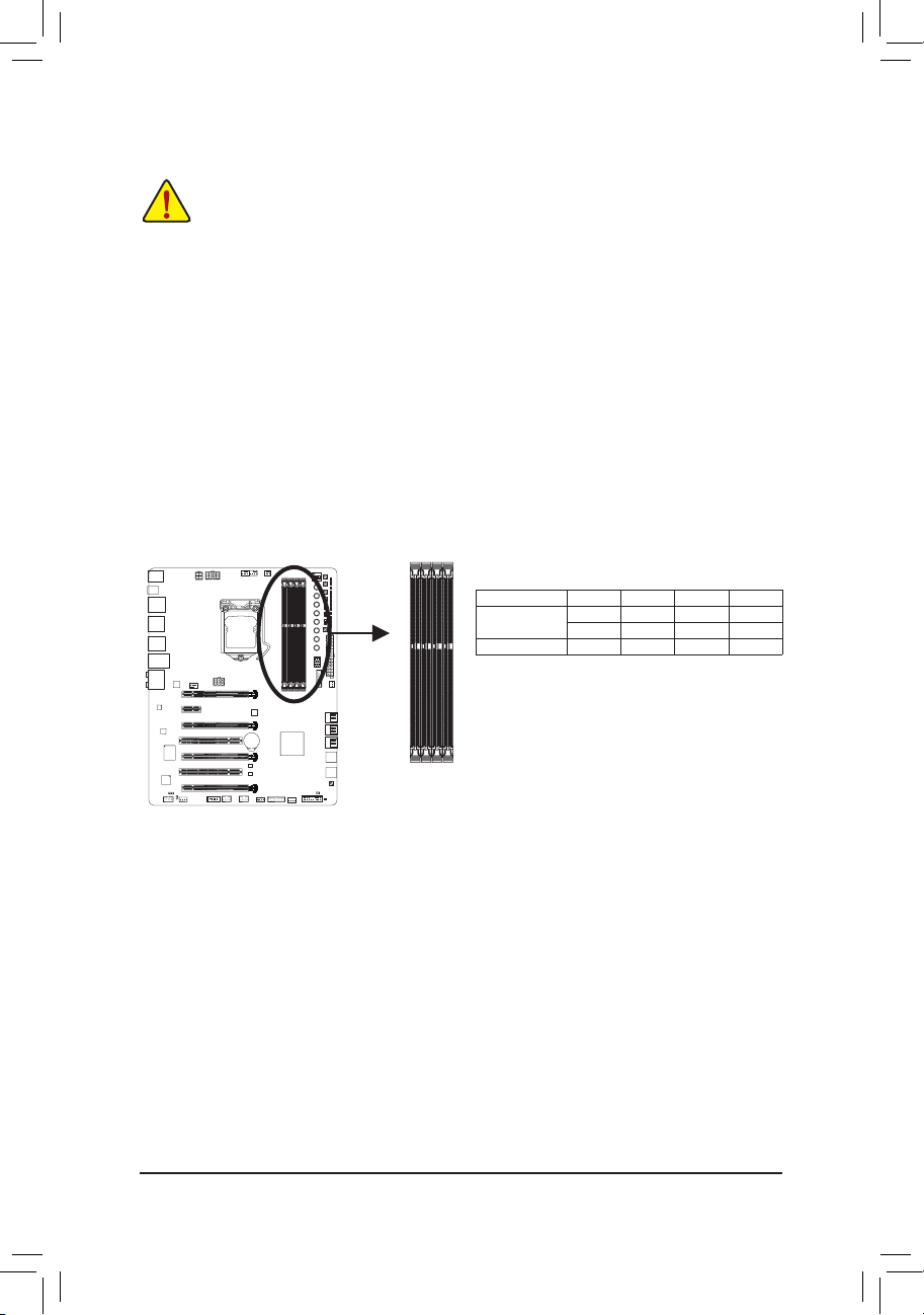
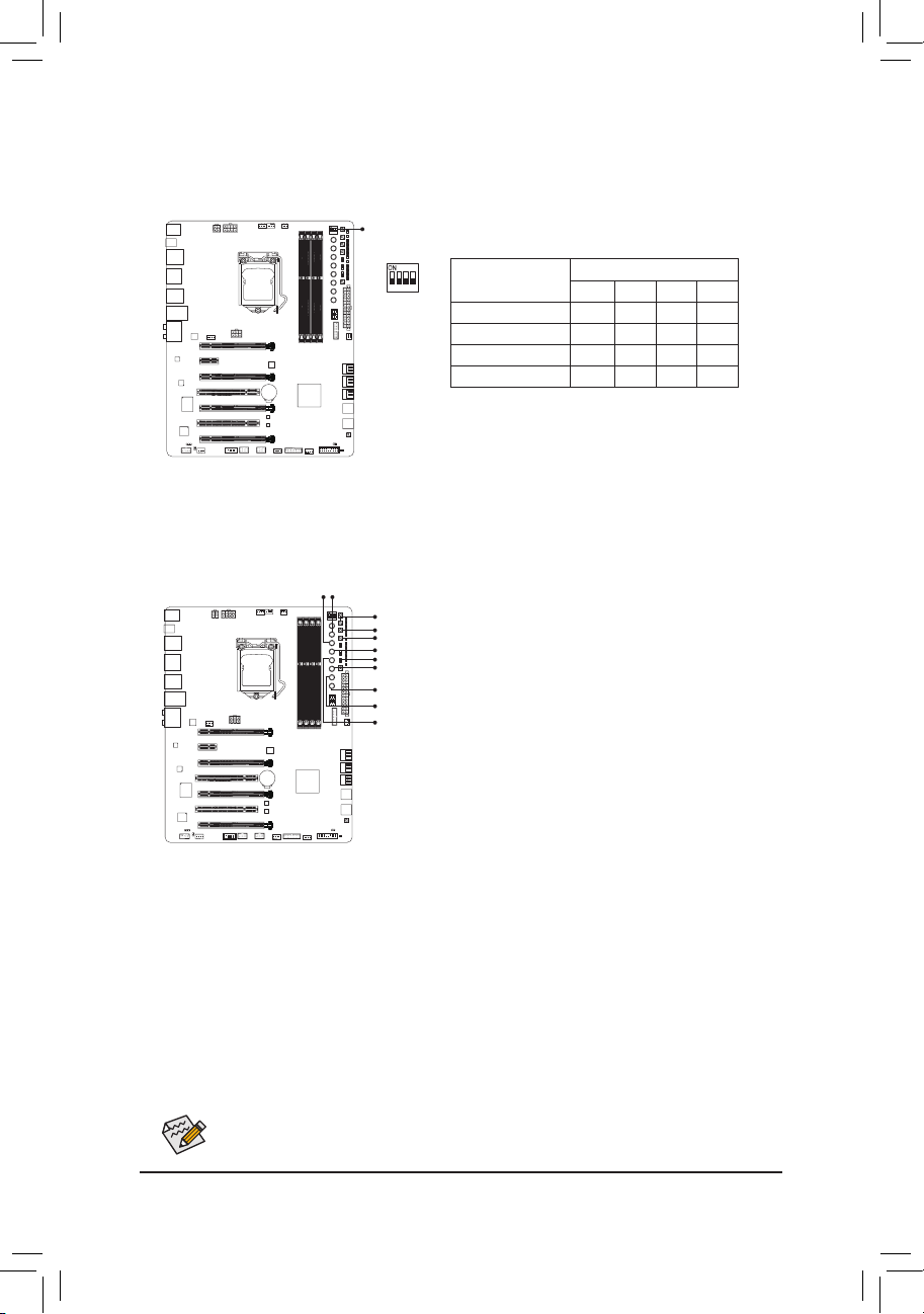
1-4-1 DualChannelMemoryConguration
This motherboard provides four DDR3 memory sockets and supports Dual Channel Technology. After the
memory is installed, the BIOS will automatically detect the specications and capacity of the memory. Enabling
Dual Channel memory mode will double the original memory bandwidth.
The four DDR3 memory sockets are divided into two channels and each channel has two memory sockets as
following:
Channel A: DDR3_2, DDR3_4
Channel B: DDR3_1, DDR3_3
DIP
4
123
Dual Channel Memory Congurations Table
Two Modules - - DS/SS - - DS/SS
Four Modules DS/SS DS/SS DS/SS DS/SS
(SS=Single-Sided, DS=Double-Sided, "- -"=No Memory)
DDR3_4 DDR3_2 DDR3_3 DDR3_1
DS/SS - - DS/SS - -
DDR3_1
DDR3_2
DDR3_3
DDR3_4
Due to CPU limitations, read the following guidelines before installing the memory in Dual Channel mode.
1. Dual Channel mode cannot be enabled if only one DDR3 memory module is installed.
2. When enabling Dual Channel mode with two or four memory modules, it is recommended that memory
of the same capacity, brand, speed, and chips be used. For optimum performance, when enabling
Dual Channel mode with two memory modules, we recommend that you install them in the DDR3_1
and DDR3_2 sockets.
- 16 -
Page 17
Hardware Installation
DIP
1 23
4
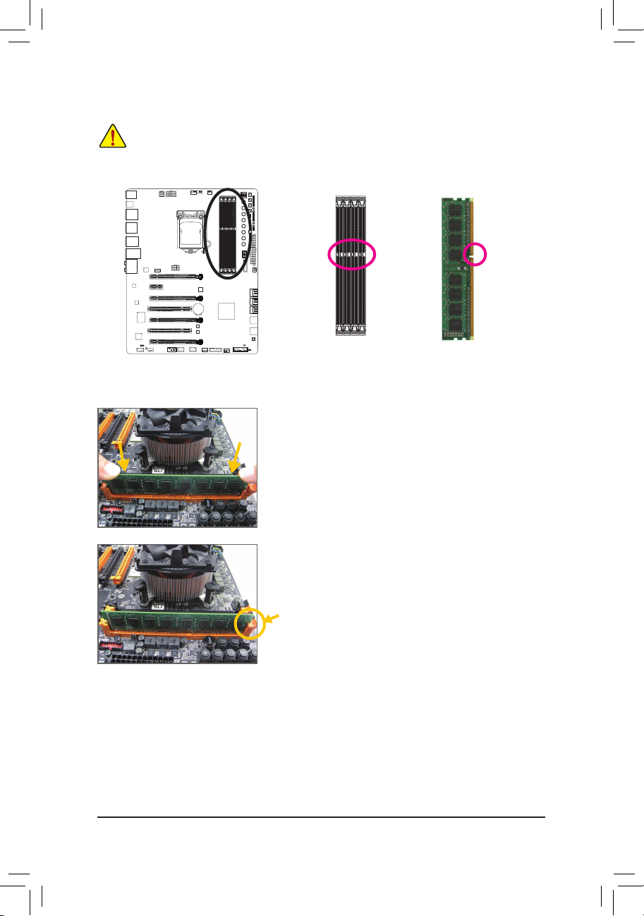
1-4-2 InstallingaMemory
Beforeinstallingamemorymodule,makesuretoturnoffthecomputerandunplugthepower
cordfromthepoweroutlettopreventdamagetothememorymodule.DDR3andDDR2DIMMs
arenotcompatibletoeachotherorDDRDIMMs.BesuretoinstallDDR3DIMMsonthis
motherboard.
DIP
4
123
Notch
DDR3 DIMM
A DDR3 memory module has a notch, so it can only t in one direction. Follow the steps below to correctly install
your memory modules in the memory sockets.
Step 1:
Note the orientation of the memory module. Spread the retaining clip
at the right end of the memory socket. Place the memory module on
the socket. As indicated in the picture on the left, place your ngers
on the top edge of the memory, push down on the memory and insert
it vertically into the memory socket.
Step 2:
The clip at the right end of the socket will snap into place when the
memory module is securely inserted.
- 17 -
Page 18
Hardware Installation
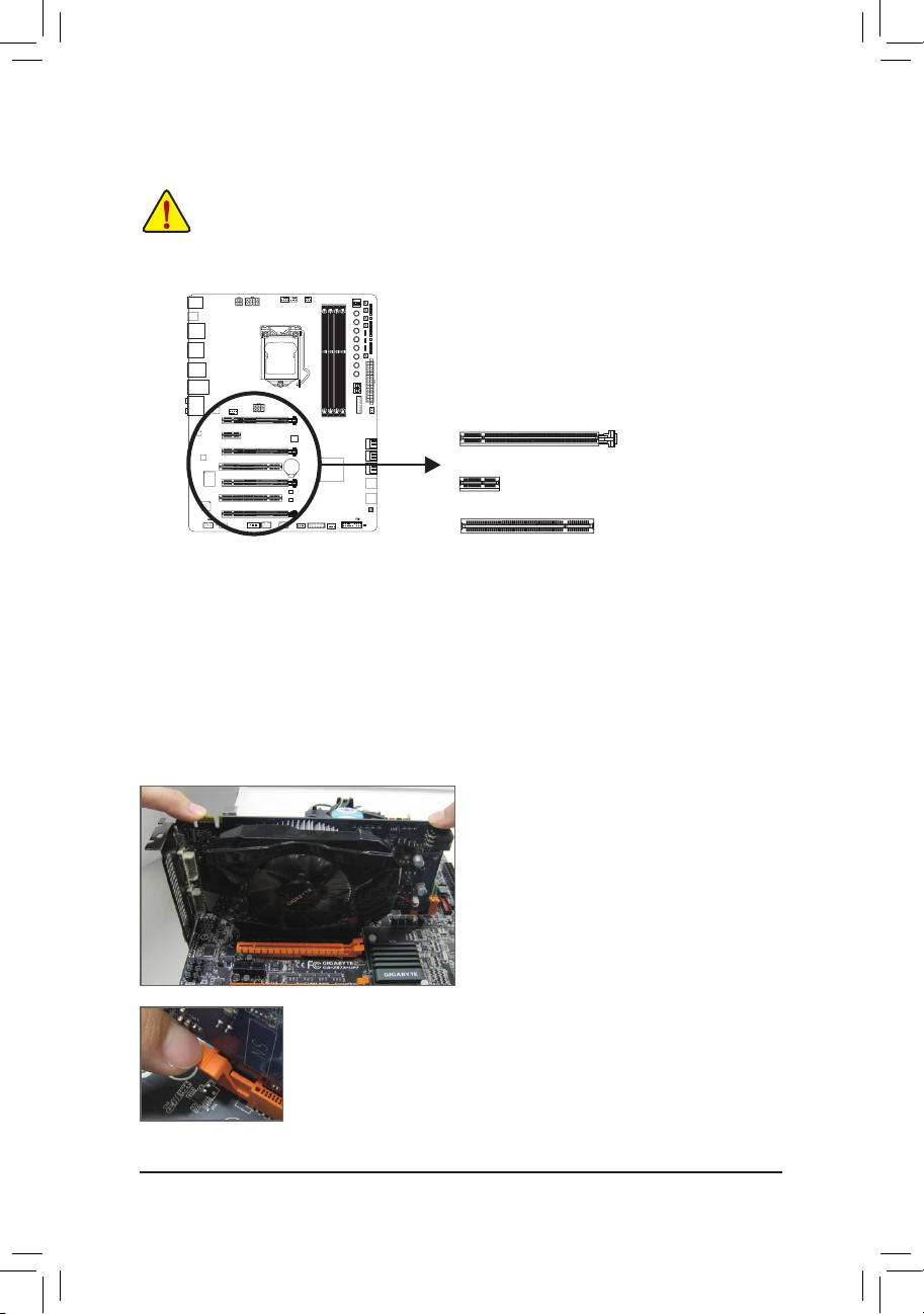
1-5 InstallingExpansionCards
Read the following guidelines before you begin to install an expansion card:
• Make sure the motherboard supports the expansion card. Carefully read the manual that came
with your expansion card.
• Always turn off the computer and unplug the power cord from the power outlet before installing an
expansion card to prevent hardware damage.
Follow the steps below to correctly install your expansion card in the expansion slot.
1. Locate an expansion slot that supports your card. Remove the metal slot cover from the chassis back panel.
2. Align the card with the slot, and press down on the card until it is fully seated in the slot.
3. Make sure the metal contacts on the card are completely inserted into the slot.
4. Secure the card's metal bracket to the chassis back panel with a screw.
5. After installing all expansion cards, replace the chassis cover(s).
6. Turn on your computer. If necessary, go to BIOS Setup to make any required BIOS changes for your
expansion card(s).
7. Install the driver provided with the expansion card in your operating system.
Example: Installing and Removing a PCI Express Graphics Card:
DIP
4
123
PCI Express x16 Slot
PCI Express x1 Slot
PCI Slot
• Installing a Graphics Card:
Gently push down on the top edge of the card until
it is fully inserted into the PCI Express slot. Make
sure the card is securely seated in the slot and
does not rock.
• Removing the Card:
Gently push back on the lever on the slot and then lift the card straight out from
the slot.
- 18 -
Page 19
Hardware Installation
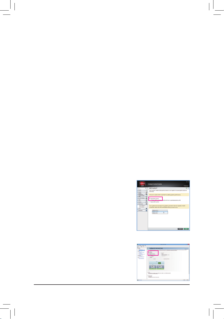
1-6 SettingupAMDCrossFire™/NVIDIA® SLI™Conguration
A.SystemRequirements
- Windows 8/7 operating system
- A CrossFire/SLI-supported motherboard with two or above PCI Express x16 slots and correct driver
- CrossFire/SLI-ready graphics cards of identical brand and chip and correct driver
(Current GPUs that support 4-/3-Way CrossFire technology include the ATI Radeon™ HD 3800, HD 4800,
HD 5800 series, and AMD Radeon™ HD 6800, HD 6900, HD 7800, HD 7900 (and above) series. For the
latest GPU support information, please refer to AMD's ofcial website.)
- CrossFire
- A power supply with sufcient power is recommended
for the power requirement)
B.ConnectingtheGraphicsCards
Step 1:
Observe the steps in "1-5 Installing an Expansion Card" and install the CrossFire/SLI graphics cards in the
PCI Express x16 slots. (To set up a 2-Way conguration, please install the graphics cards in the PCIEX16 and
PCIEX8 slots. To set up a 3-Way CrossFire conguration, we recommend installing the graphics cards in the
PCIEX16 and PCIEX8, and PCIEX4_1 slots.)
(Note 1)
/SLI bridge connectors
(Note 2)
(Refer to the manual of your graphics cards
Step 2:
Insert the CrossFire
(Note 1)
/SLI bridge connectors in the CrossFire/SLI gold edge connectors on top of the cards.
Step 3:
Plug the display cable into the graphics card on the PCIEX16 slot.
C.ConguringtheGraphicsCardDriver
C-1.ToEnableCrossFireFunction
After installing the graphics card driver in the operating system,
go to the CatalystControlCenter. Browse to Performance\AMD
CrossFireX™Conguration and ensure the EnableCrossFireX™ check
box is selected. and click Apply.(Available combination options are
dependent on the number of graphics cards.)
C-2.ToEnableSLIFunction
After installing the graphics card driver in the operating system, go to
the NVIDIAControlPanel. Browse to the CongureSLI,Surround,
Physx screen and ensure Maximize3Dperformance is enabled.
- 19 -
Page 20
Hardware Installation
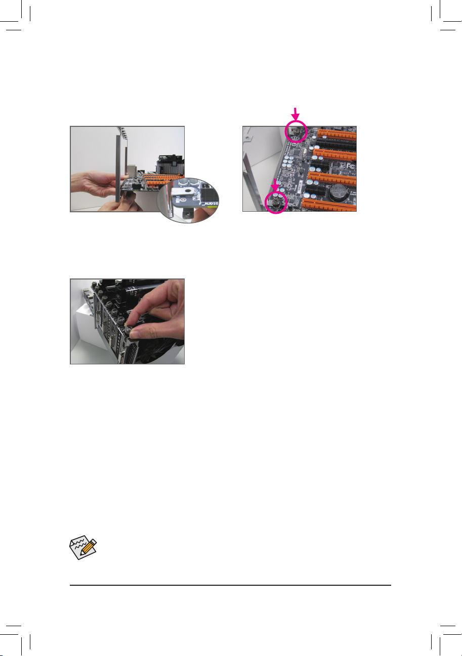
D.InstallingtheOCBrace
(Note 3)
OC Brace allows extreme overclockers and system testers to safely install up to four graphics cards in an open
case or test bed without risking PCIe slot damage or preventing cards not showing up in the OS due to poor
contact with PCIe slot. Refer to the following installation instructions:
Step 1:
As shown, align the screw holes on the OC Brace
and back plate with the screw holes near the PCIe
slots on the motherboard.
Step 2:
Fasten two of the included thumb screws (starting
from the screw hole near the back panel audio
connectors) to hold the OC Brace in place.
Step 3:
After installing the graphics cards, use the included
thumb screws to secure the metal brackets of the
graphics cards to the OC Brace.
(Note 1) The bridge connectors may be needed or not depending on your graphics cards.
(Note 2) When two or more graphics cards are installed, we recommend that you connect the power cable
from the power supply to the OC_PEG connetctor to ensure system stability.
(Note 3) The components received may vary in appearance from the products illustrated.
Procedure and driver screen for enabling CrossFire/SLI technology may differ by graphics cards and
driver version. Refer to the manual that came with your graphics cards for more information about
enabling CrossFire/SLI technology.
- 20 -
Page 21
Hardware Installation
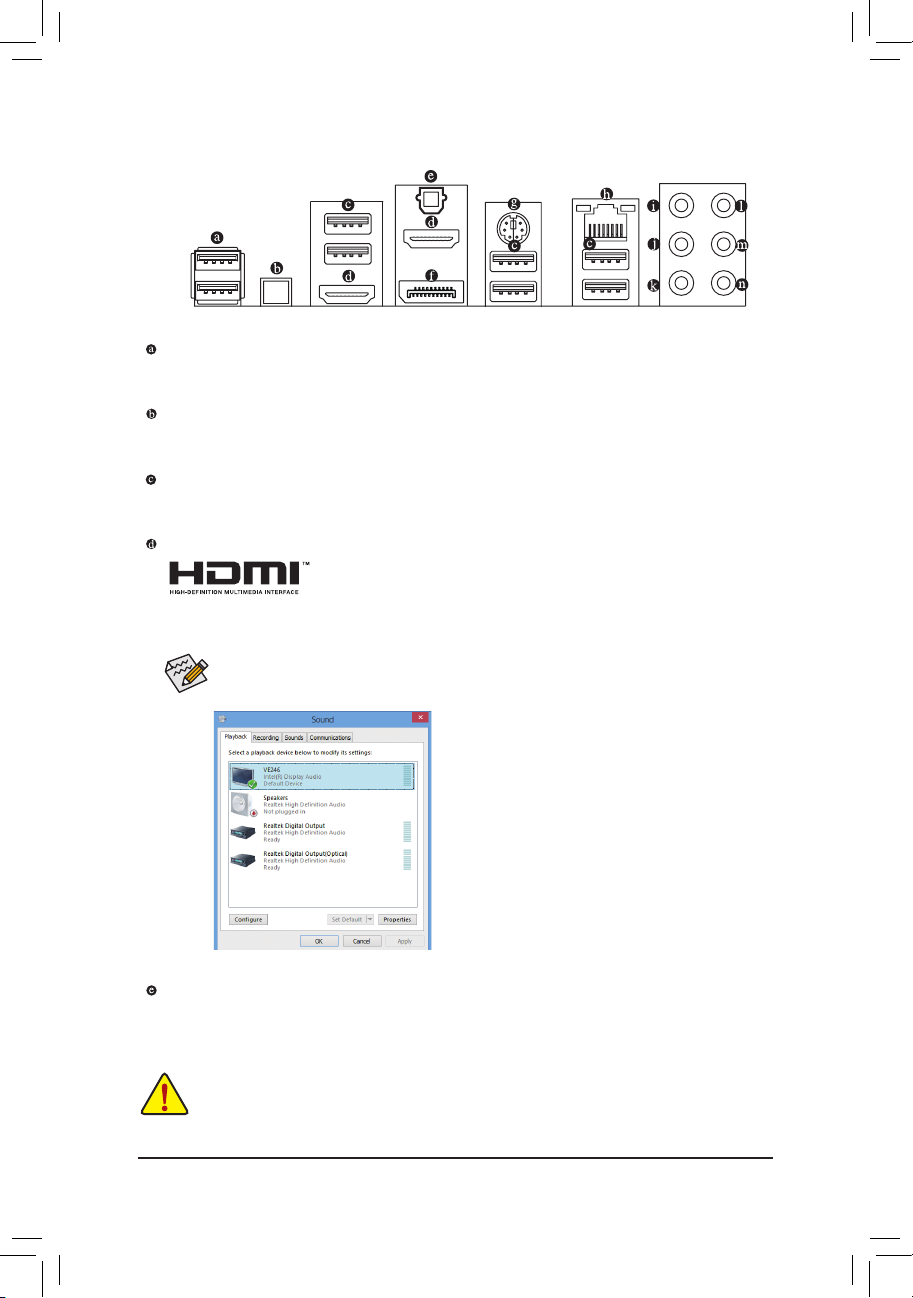
1-7 BackPanelConnectors
USB2.0/1.1Port
The USB port supports the USB 2.0/1.1 specication. Use this port for USB devices such as a USB
keyboard/mouse, USB printer, USB ash drive and etc.
OCIgnitionbutton
The OC Ignition feature maintains power to your motherboard and connected components while the system
is shut down. After pressing this button, be sure to press the power button to take effect.
USB3.0/2.0Port
The USB 3.0 port supports the USB 3.0 specication and is compatible to the USB 2.0/1.1 specication.
Use this port for USB devices such as a USB keyboard/mouse, USB printer, USB ash drive and etc.
HDMIPort
The HDMI port is HDCP compliant and supports Dolby True HD and DTS HD
Master Audio formats. It also supports up to 192KHz/24bit 8-channel LPCM audio
output. You can use this port to connect your HDMI-supported monitor. The maximum supported resolution
is 4096x2160, but the actual resolutions supported are dependent on the monitor being used.
After installing the HDMI device, make sure to set the default sound playback device to HDMI.
(The item name may differ depending on your operating system. The screenshot below is from
Windows 8.)
In Windows 8, select All apps>Control Panel>Hardware
and Sound>Sound>Playback, set Intel(R) Display Audio
to the default playback device.
OpticalS/PDIFOutConnector
This connector provides digital audio out to an external audio system that supports digital optical audio.
Before using this feature, ensure that your audio system provides an optical digital audio in connector.
• When removing the cable connected to a back panel connector, rst remove the cable from your
device and then remove it from the motherboard.
• When removing the cable, pull it straight out from the connector. Do not rock it side to side to prevent
an electrical short inside the cable connector.
- 21 -
Page 22
Hardware Installation
DisplayPort
DisplayPort delivers high quality digital imaging and audio, supporting bi-directional audio transmission.
DisplayPort can support both DPCP and HDCP content protection mechanisms. You can use this port to
connect your DisplayPort-supported monitor. Note: The DisplayPort Technology can support a maximum
resolution of 3840x2160 but the actual resolutions supported depend on the monitor being used.
After installing the DisplayPort device, make sure the default device for sound playback is the
DisplayPort device. (The item name may differ from operating system. Refer to the HDMI settings
information on the previous page for the conguration dialog box.)
TripleDisplayCongurationsfortheOnboardGraphics:
Triple-display congurations are supported after you install motherboard drivers in OS. Only dual-display
congurations are supported during the BIOS Setup or POST process.
PS/2Keyboard/MousePort
Use this port to connect a PS/2 mouse or keyboard.
RJ-45LANPort
The Gigabit Ethernet LAN port provides Internet connection at up to 1 Gbps data rate. The following
describes the states of the LAN port LEDs.
Connection/
Speed LED
Activity LED
LAN Port
Connection/Speed LED:
State Description
Orange 1 Gbps data rate
Green 100 Mbps data rate
Off 10 Mbps data rate
Activity LED:
State Description
Blinking Data transmission or receiving is occurring
On No data transmission or receiving is occurring
Center/SubwooferSpeakerOutJack(Orange)
Use this audio jack to connect center/subwoofer speakers in a 5.1/7.1-channel audio conguration.
RearSpeakerOutJack(Black)
This jack can be used to connect front speakers in a 4/5.1/7.1-channel audio conguration.
SideSpeakerOutJack(Gray)
Use this audio jack to connect side speakers in a 7.1-channel audio conguration.
LineInJack(Blue)
The line in jack. Use this audio jack for line in devices such as an optical drive, walkman, etc.
LineOutJack(Green)
The line out jack. Use this audio jack for a headphone or 2-channel speaker. This jack can be used to
connect front speakers in a 4/5.1/7.1-channel audio conguration.
MicInJack(Pink)
The default Mic in jack. Microphones must be connected to this jack.
The audio jacks can be recongured to perform different functions via the audio software (supported
functions for each jack may vary based on hardware specication). Only microphones still MUST
be connected to the default Mic in jack. Refer to the instructions on setting up a 2/4/5.1/7.1-channel
audio conguration in Chapter 6, "Conguring 2/4/5.1/7.1-Channel Audio."
- 22 -
Page 23
Hardware Installation
1-8 OnboardButtons,Switches,andLEDs
BIOSSwitchesandBIOSLEDIndicators
The BIOS switch (BIOS_SW) allows users to easily select a different BIOS for boot up or overclocking,
helping to reduce BIOS failure during overclocking. The SB switch allows enabling or disabling of the Dual
BIOS function. The LED indicator (MBIOS_LED/BBIOS_LED) shows which BIOS is active.
DIP
4
123
SB
BIOS_SW
BBIOS_LED
MBIOS_LED
QuickButtons
This motherboard has four quick buttons: Power, Reset, Clear CMOS, and Clear Battery. The power button and
reset button allow users to quickly turn on/off or reset the computer in an open-case environment when they
want to change hardware components or conduct hardware testing. Use the clear CMOS button to clear the
BIOS conguration and reset the CMOS values to factory defaults when needed. The Clear Battery button has
the same function as removing the battery from the motherboard.
DIP
RST_SW
4
123
PW_SW
CMOS_SW
BIOS Switches:
BIOS_SW
2
1: Main BIOS (Boot from the main BIOS)
1
2
2: Backup BIOS (Boot from the backup BIOS)
1
SB
2
1: Dual BIOS
1
2
2: Single BIOS
1
BIOS LED Indicators:
MBIOS_LED (The main BIOS is active)
BBIOS_LED (The backup BIOS is active)
PW_SW:Power button
RST_SW:Reset button
CMOS_SW:Clear CMOS Button
CBAT_SW:Clear Battery Button
CBAT_SW
• Always turn off your computer and unplug the power cord from the power outlet before using
the clear CMOS button.
• Always turn off the power of the power supply before using the clear battery button. After pressing
this button, make sure to wait for ve minutes before you turn on the computer.
• Do not use the clear CMOS or clear battery button when the system is on, or the system may
shut down and data loss or damage may occur.
• After system restart, go to BIOS Setup to load factory defaults (select Load Optimized Defaults) or
manually congure the BIOS settings (refer to Chapter 2, "BIOS Setup," for BIOS congurations).
- 23 -
Page 24
Hardware Installation
OCPCIeswitch(PCIE_SW)
(GA-IVB)
DIP
1 2 3
4
ATX_12V_2X3
F_USB3 (Front Panel)
This switch allows you to manually turn off specic PCI Express slot(s) (except for the PCI Express x1 slot)
without physical removal.
DIP
4
123
PCIE_SW
PCIE_SW
DIP
1 2 3 4
Slot DIP Setting
DIP 1 DIP 2 DIP 3 DIP 4
Disabling PCIEX16_1
ON
OFF OFF
OFF
Disabling PCIEX4_1 OFF ON OFF OFF
Disabling PCIEX8_1 OFF
OFF ON
OFF
Disabling PCIEX4_2 OFF OFF OFF ON
OCButtons
GIGABYTE's unique OC buttons help enthusiasts and overclockers not only get the most performance from
their hardware, but also the absolute most enjoyable OC experience with features like overclocking the CPU in
real-time, automatically loading the most optimized overclocking conguration for the processor and memory,
and loading users' customized settings, etc.
RATIO_UP
RATIO_DW
DIP
4
123
MEM_SAFE
DTB
SET_LOCK
FREQ_DW
TGR
GEAR
TAG
TURBO
FREQ_UP
GearButton(GEAR):
Changes BCLK stepping to 0.1 MHz or 1 MHz.
OCTurboButton(TURBO):
Press this button to load the most optimized GIGABYTE overclocking
conguration for your processor and memory.
OCTagButton(TAG):
This button allows you to load your customized settings (please dene the TAG prole on the Save&Exit menu in BIOS
Setup) so you can apply your custom settings after clearing CMOS.
CPURatioDownButton(RATIO_DW):
Lowers the CPU ratio.
CPURatioUpButton(RATIO_UP):
Raises the CPU ratio.
CPUBCLKDownButton(FREQ_DW):
Lowers the CPU base clock.
CPUBCLKUpButton(FREQ_UP):
Raises the CPU base clock.
MemorySafeButton(MEM_SAFE):
Pressing the Memory Safe button engages a fail- safe mode that allows the system to boot in a safe memory conguration,
regardless of the DDR3 DIMM speed or CAS rating. (Note: Engaging Memory Safe may impact system memory performance.)
SettingsLockButton(SET_LOCK):
The GIGABYTE Settings Lock button allows the system to automatically remember your last successful settings, even
after clearing CMOS. With one touch, the Settings Lock button can quickly revert to the previous good settings; a very
useful tool for overclockers tuning their BIOS to perfection.
Before using the overclocking buttons, make sure to load the optimized defaults in BIOS Setup to
return the BIOS settings to factory defaults.
- 24 -
Page 25
Hardware Installation
SMB_CPT
(GA-IVB)
CLR_CMOSCIDIS_ME
GP15_CPT
(GA-IVB)
XDP_CPU
XDP_PCH
(GA-IVB)
DIP
123
DIP
123
DIP
123
DIP
123
PWM Switch (X58A-OC)
BIOS Switcher (SW4)
PCIe Control (Z87X-UP7)
DIP
1 2 3
4
DIP
1 2 3 4
DIP
1 2 3
4
DIP
1 2 3 4
ATX_12V_2X3
F_USB3 (Front Panel)
SMB_CPT
(GA-IVB)
CLR_CMOSCIDIS_ME
GP15_CPT
(GA-IVB)
XDP_CPU
XDP_PCH
(GA-IVB)
DIP
123
DIP
123
DIP
123
DIP
123
PWM Switch (X58A-OC)
BIOS Switcher (SW4)
PCIe Control (Z87X-UP7)
DIP
1 2 3
4
DIP
1 2 3 4
DIP
1 2 3
4
DIP
1 2 3 4
ATX_12V_2X3
F_USB3 (Front Panel)
SMB_CPT
(GA-IVB)
CLR_CMOSCIDIS_ME
GP15_CPT
(GA-IVB)
XDP_CPU
XDP_PCH
(GA-IVB)
DIP
123
DIP
123
DIP
123
DIP
123
PWM Switch (X58A-OC)
BIOS Switcher (SW4)
PCIe Control (Z87X-UP7)
DIP
1 2 3
4
DIP
1 2 3 4
DIP
1 2 3
4
DIP
1 2 3 4
ATX_12V_2X3
F_USB3 (Front Panel)
SMB_CPT
(GA-IVB)
CLR_CMOSCIDIS_ME
GP15_CPT
(GA-IVB)
XDP_CPU
XDP_PCH
(GA-IVB)
DIP
123
DIP
123
DIP
123
DIP
123
PWM Switch (X58A-OC)
BIOS Switcher (SW4)
PCIe Control (Z87X-UP7)
DIP
1 2 3
4
DIP
1 2 3 4
DIP
1 2 3
4
DIP
1 2 3 4
ATX_12V_2X3
F_USB3 (Front Panel)
SMB_CPT
(GA-IVB)
CLR_CMOSCIDIS_ME
GP15_CPT
(GA-IVB)
XDP_CPU
XDP_PCH
(GA-IVB)
DIP
123
DIP
123
DIP
123
DIP
123
PWM Switch (X58A-OC)
BIOS Switcher (SW4)
PCIe Control (Z87X-UP7)
DIP
1 2 3
4
DIP
1 2 3 4
DIP
1 2 3
4
DIP
1 2 3 4
ATX_12V_2X3
F_USB3 (Front Panel)
SMB_CPT
(GA-IVB)
CLR_CMOSCIDIS_ME
GP15_CPT
(GA-IVB)
XDP_CPU
XDP_PCH
(GA-IVB)
DIP
123
DIP
123
DIP
123
DIP
123
PWM Switch (X58A-OC)
BIOS Switcher (SW4)
PCIe Control (Z87X-UP7)
DIP
1 2 3
4
DIP
1 2 3 4
DIP
1 2 3
4
DIP
1 2 3 4
ATX_12V_2X3
F_USB3 (Front Panel)
SMB_CPT
(GA-IVB)
CLR_CMOSCIDIS_ME
GP15_CPT
(GA-IVB)
XDP_CPU
XDP_PCH
(GA-IVB)
DIP
123
DIP
123
DIP
123
DIP
123
PWM Switch (X58A-OC)
BIOS Switcher (SW4)
PCIe Control (Z87X-UP7)
DIP
1 2 3
4
DIP
1 2 3 4
DIP
1 2 3
4
DIP
1 2 3 4
ATX_12V_2X3
F_USB3 (Front Panel)
SMB_CPT
(GA-IVB)
CLR_CMOSCIDIS_ME
GP15_CPT
(GA-IVB)
XDP_CPU
XDP_PCH
(GA-IVB)
DIP
123
DIP
123
DIP
123
DIP
123
PWM Switch (X58A-OC)
BIOS Switcher (SW4)
PCIe Control (Z87X-UP7)
DIP
1 2 3
4
DIP
1 2 3 4
DIP
1 2 3
4
DIP
1 2 3 4
ATX_12V_2X3
F_USB3 (Front Panel)
SMB_CPT
(GA-IVB)
CLR_CMOSCIDIS_ME
GP15_CPT
(GA-IVB)
XDP_CPU
XDP_PCH
(GA-IVB)
DIP
123
DIP
123
DIP
123
DIP
123
PWM Switch (X58A-OC)
BIOS Switcher (SW4)
PCIe Control (Z87X-UP7)
DIP
1 2 3
4
DIP
1 2 3 4
DIP
1 2 3
4
DIP
1 2 3 4
ATX_12V_2X3
F_USB3 (Front Panel)
SMB_CPT
(GA-IVB)
CLR_CMOSCIDIS_ME
GP15_CPT
(GA-IVB)
XDP_CPU
XDP_PCH
(GA-IVB)
DIP
123
DIP
123
DIP
123
DIP
123
PWM Switch (X58A-OC)
BIOS Switcher (SW4)
PCIe Control (Z87X-UP7)
DIP
1 2 3
4
DIP
1 2 3 4
DIP
1 2 3
4
DIP
1 2 3 4
ATX_12V_2X3
F_USB3 (Front Panel)
SMB_CPT
(GA-IVB)
CLR_CMOSCIDIS_ME
GP15_CPT
(GA-IVB)
XDP_CPU
XDP_PCH
(GA-IVB)
DIP
123
DIP
123
DIP
123
DIP
123
PWM Switch (X58A-OC)
BIOS Switcher (SW4)
PCIe Control (Z87X-UP7)
DIP
1 2 3
4
DIP
1 2 3 4
DIP
1 2 3
4
DIP
1 2 3 4
ATX_12V_2X3
F_USB3 (Front Panel)
SMB_CPT
(GA-IVB)
CLR_CMOSCIDIS_ME
GP15_CPT
(GA-IVB)
XDP_CPU
XDP_PCH
(GA-IVB)
DIP
123
DIP
123
DIP
123
DIP
123
PWM Switch (X58A-OC)
BIOS Switcher (SW4)
PCIe Control (Z87X-UP7)
DIP
1 2 3
4
DIP
1 2 3 4
DIP
1 2 3
4
DIP
1 2 3 4
ATX_12V_2X3
F_USB3 (Front Panel)
DirecttoBIOSButton(DTB):
This button helps users more easily to directly enter the BIOS at any time before rebooting the system. (Pressing this
button during the POST process allows you to immediately enter BIOS Setup. If the button is pressed after the POST
process, the system will enter BIOS Setup directly on next boot.)
OCTriggerSwitch(TGR):
This switch allows the overclockers to jump between low and extremely high frequencies in an instant. After remaining at
a low frequency during system boot and OS optimization, the overclocker can then engage the Trigger Switch to instantly
hit the target frequency, save their score submission, grab a screen shot, and watch the records tumble.
2
1: Target frequency set in BIOS Setup or other overclocking application.
1
2
2: Safe frequency (using the lowest CPU ratio, which may vary by CPU)
1
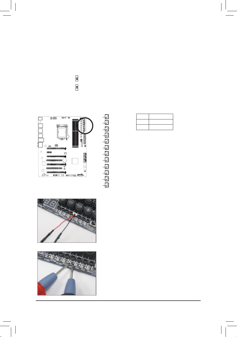
OnboardVoltageMeasurementModule
Users can use a multimeter to measure component voltages, including VRIN, VCORE, VRING, VIOD, VIOA,
VAXG, VSA, PCHV, and VDIMM. You can employ one of the following two ways to measure component
voltages.
DIP
4
123
VRINPin 1
VCORE0Pin 1
VCORE1
Pin 1
VCORE2
Pin 1
VCORE3
Pin 1
VRING
Pin 1
VIOD
Pin 1
VIOA
Pin 1
VAXG
Pin 1
VSA
Pin 1
PCHV
Pin 1
VDIMM
Pin 1
Pin No. Denition
1 Power
2 GND
Method I (Using the included voltage measurement cable):
Steps:
Connect the included voltage measurement cable to a voltage
measurement header and your multimeter as shown. Please note
the red wire is the positive and must be connected to the pin 1
(Power).
Method II (Connecting the multimeter directly):
Steps:
Connect the red lead of the multimeter to the pin 1 (Power) of
a voltage measurement point and the black lead to the pin 2
(ground).
- 25 -
Page 26
Hardware Installation
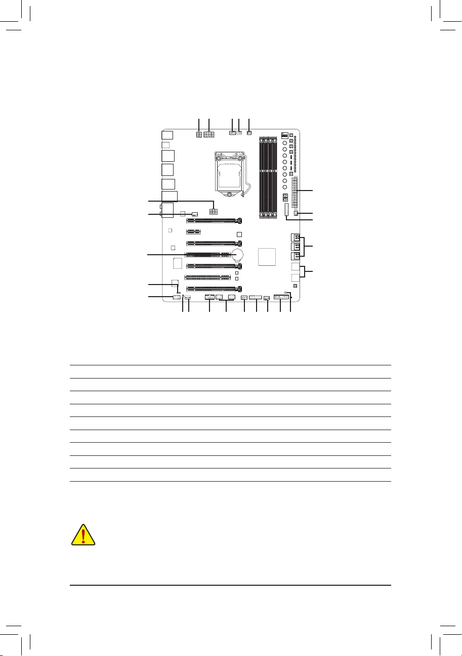
1-9 Internal Connectors
3
5
1
1 4 6 5
DIP
4
1 23
2
5
12
16
10
9
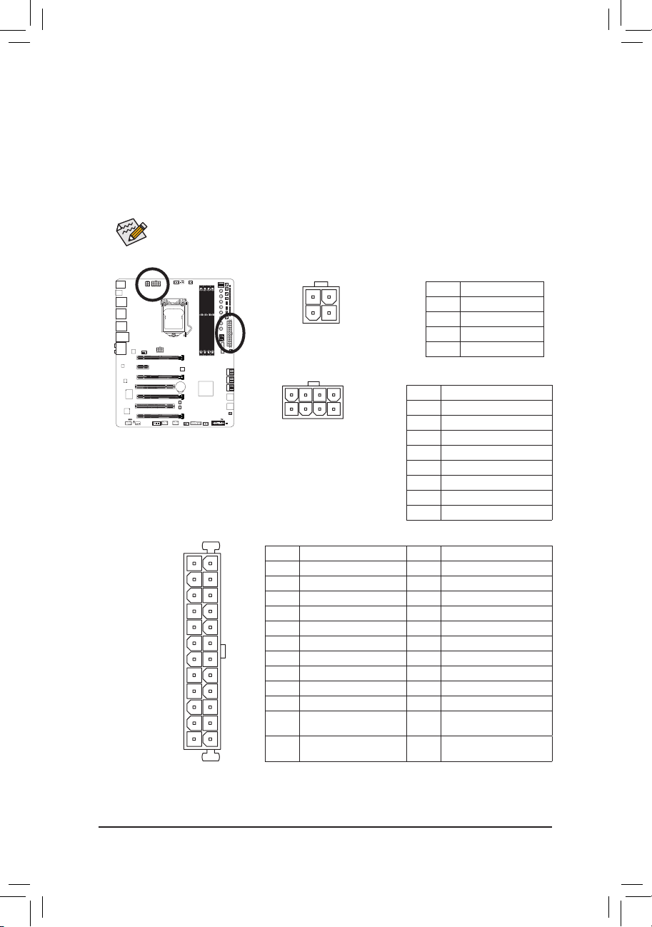
1) ATX_12V_2X4/ATX_12V
2) ATX
3) OC_PEG
4) CPU_FAN
5) SYS_FAN1/2/3/4/5/6
6) CPU_OPT
7) SATA30/1/2/3/4/5
8) F_PANEL
15
511
12
5
13 5
8
10) SPDIF_IN
11) SPDIF_O
12) F_USB30_1/F_USB30_2
13) F_USB1/F_USB2
14) F_USB3/F_USB4
15) COMA
16) BAT
17) CLR_CMOS
7
14
17
9) F_AUDIO
Read the following guidelines before connecting external devices:
• First make sure your devices are compliant with the connectors you wish to connect.
• Before installing the devices, be sure to turn off the devices and your computer. Unplug the power
cord from the power outlet to prevent damage to the devices.
• After installing the device and before turning on the computer, make sure the device cable has
been securely attached to the connector on the motherboard.
- 26 -
Page 27
Hardware Installation
1/2)ATX_12V/ATX_12V_2X4/ATX(2x2,2x412VPowerConnectorsand2x12MainPower
Connector)
With the use of the power connector, the power supply can supply enough stable power to all the components
on the motherboard. Before connecting the power connector, rst make sure the power supply is turned
off and all devices are properly installed. The power connector possesses a foolproof design. Connect the
power supply cable to the power connector in the correct orientation.
The 12V power connector mainly supplies power to the CPU. If the 12V power connector is not connected,
the computer will not start.
To meet expansion requirements, it is recommended that a power supply that can withstand high
power consumption be used (500W or greater). If a power supply is used that does not provide the
required power, the result can lead to an unstable or unbootable system.
DIP
4
123
3
1
5
1
ATX_12V_2X4
4
2
ATX_12V
8
4
ATX_12V:
Pin No. Denition
1 GND
2 GND
3 +12V
4 +12V
ATX_12V_2X4:
Pin No. Denition
1 GND (Only for 2x4-pin 12V)
2 GND (Only for 2x4-pin 12V)
3 GND
4 GND
5 +12V (Only for 2x4-pin 12V)
6 +12V (Only for 2x4-pin 12V)
7 +12V
8 +12V
ATX
ATX:
2412
Pin No. Denition Pin No. Denition
1 3.3V 13 3.3V
2 3.3V 14 -12V
3 GND 15 GND
4 +5V 16 PS_ON (soft On/Off)
5 GND 17 GND
6 +5V 18 GND
7 GND 19 GND
8 Power Good 20 -5V
9 5VSB (stand by +5V) 21 +5V
10 +12V 22 +5V
11 +12V (Only for 2x12-pin
131
ATX)
12 3.3V (Only for 2x12-pin
ATX)
23 +5V (Only for 2x12-pin ATX)
24 GND (Only for 2x12-pin
ATX)
- 27 -
Page 28
Hardware Installation
DEBUG
PORT
(H61M-D2)
ACPI_CPT
(GA-IVB)
BIOS_PH
(GA-IVB)
SMB_CPT
(GA-IVB)
CLR_CMOS
CI
DIS_ME
GP15_CPT
(GA-IVB)
XDP_CPU
XDP_PCH
(GA-IVB)
PWM Switch (SW1)(X79-UD7)
DIP
1 2 3 4 5
ATX_12V_2X3
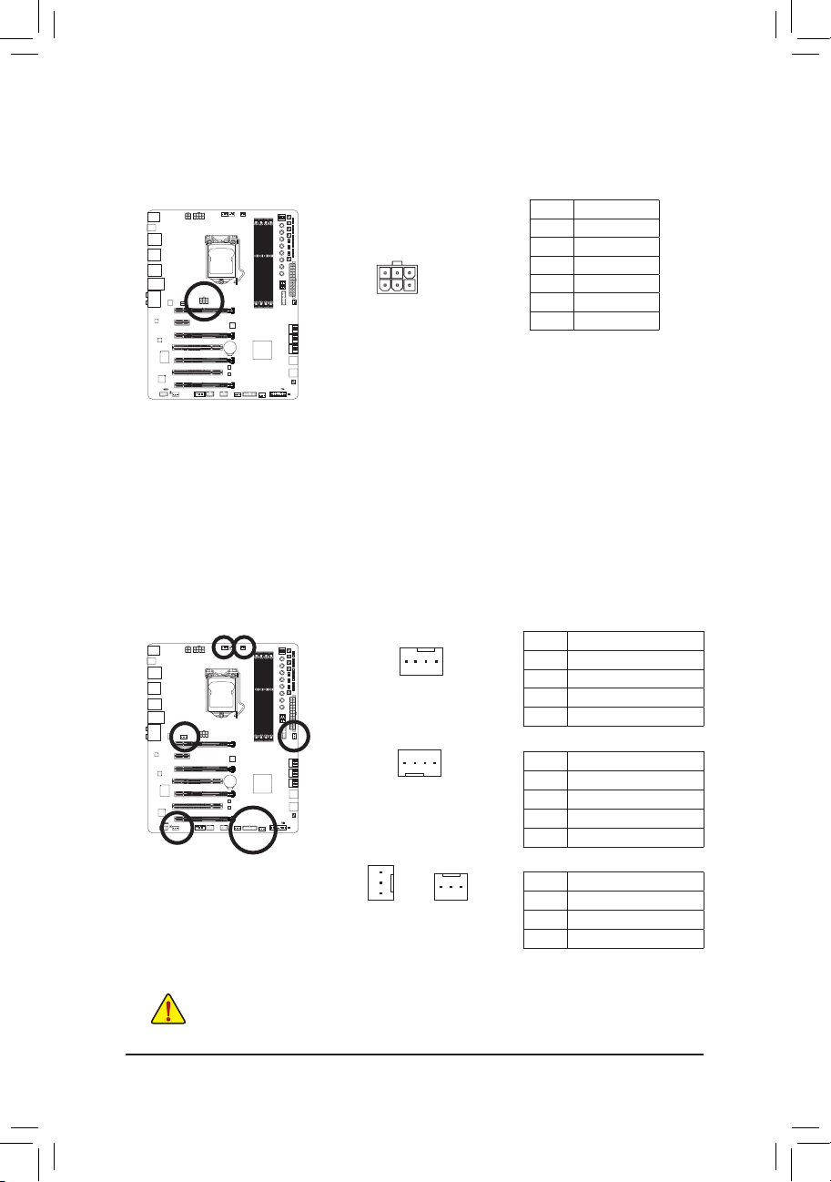
3) OC_PEG(PCIePowerConnector)
The power connector provides auxiliary power to the onboard PCI Express x16 slots. When two or more
graphics cards are installed, we recommend that you connect the 2x3 power cable from the power supply
to this connector to ensure system stability.
DIP
4
123
6
3
4
1
Pin No. Denition
1 +12V
2 +12V
3 +12V
4 GND
5 GND
6 GND
4/5)CPU_FAN/SYS_FAN1/2/3/4/5/6(FanHeaders)
The motherboard has a 4-pin CPU fan header (CPU_FAN), four 4-pin (SYS_FAN1/SYS_FAN2/SYS_FAN3/
SYS_FAN4) and two 3-pin (SYS_FAN5/SYS_FAN6) system fan headers. Most fan headers possess a
foolproof insertion design. When connecting a fan cable, be sure to connect it in the correct orientation
(the black connector wire is the ground wire). The speed control function requires the use of a fan with
fan speed control design. For optimum heat dissipation, it is recommended that a system fan be installed
inside the chassis.
DIP
4
123
CPU_FAN
1
1
SYS_FAN1/2/3/4
1
SYS_FAN5
SYS_FAN6
• Be sure to connect fan cables to the fan headers to prevent your CPU and system from
overheating. Overheating may result in damage to the CPU or the system may hang.
• These fan headers are not conguration jumper blocks. Do not place a jumper cap on the headers.
- 28 -
1
CPU_FAN:
Pin No. Denition
1 GND
2 +12V
3 Sense
4 Speed Control
SYS_FAN1/2/3/4:
Pin No. Denition
1 GND
2 +12V /Speed Control
3 Sense
4 VCC
SYS_FAN5/6:
Pin No. Denition
1 GND
2 +12V
3 NC
Page 29
Hardware Installation
6) CPU_OPT(WaterCoolingCPUFanHeader)
G.QBOFM
G.QBOFM
G.QBOFM
The fan header is 4-pin and possesses a foolproof insertion design. When connecting a fan cable, be sure
to connect it in the correct orientation (the black connector wire is the ground wire). The speed control
function requires the use of a fan with fan speed control design.
DIP
4
123
1
Pin No. Denition
1 GND
2 +12V /Speed Control
3 Sense
4 VCC
7) SATA30/1/2/3/4/5(SATA6Gb/sConnectors)
The SATA connectors conform to SATA 6Gb/s standard and are compatible with SATA 3Gb/s and SATA
1.5Gb/s standard. Each SATA connector supports a single SATA device. The Intel® Z87 Chipset supports
RAID 0, RAID 1, RAID 5, and RAID 10. Refer to Chapter 3, "Conguring SATA Hard Drive(s)," for instructions
on conguring a RAID array.
DIP
4
123
SATA 3
7
7
5 3 1
4 2 0
1
1
Pin No. Denition
1 GND
2 TXP
3 TXN
4 GND
5 RXN
6 RXP
7 GND
• A RAID 0 or RAID 1 conguration requires at least two hard drives. If more than two hard drives
are to be used, the total number of hard drives must be an even number.
• A RAID 5 conguration requires at least three hard drives. (The total number of hard drives does
not have to be an even number.)
• A RAID 10 conguration requires four hard drives.
- 29 -
Page 30
Hardware Installation
8) F_PANEL(FrontPanelHeader)
Connect the power switch, reset switch, speaker, chassis intrusion switch/sensor and system status indicator
on the chassis to this header according to the pin assignments below. Note the positive and negative pins
before connecting the cables.
DIP
4
123
• PLED/PWR_LED(Power LED, Yellow/Purple):
System Status LED
S0 On
S3/S4/S5 Off
Connects to the power status indicator on the chassis front panel. The LED
is on when the system is operating. The LED is off when the system is in S3/
S4 sleep state or powered off (S5).
• PW (Power Switch, Red):
Connects to the power switch on the chassis front panel. You may congure the way to turn off your
system using the power switch (refer to Chapter 2, "BIOS Setup," "Power Management," for more
information).
• SPEAK(Speaker, Orange):
Connects to the speaker on the chassis front panel. The system reports system startup status by issuing
a beep code. One single short beep will be heard if no problem is detected at system startup.
• HD (Hard Drive Activity LED, Blue):
Connects to the hard drive activity LED on the chassis front panel. The LED is on when the hard drive
is reading or writing data.
• RES(Reset Switch, Green):
Connects to the reset switch on the chassis front panel. Press the reset switch to restart the computer
if the computer freezes and fails to perform a normal restart.
• CI (Chassis Intrusion Header, Gray):
Connects to the chassis intrusion switch/sensor on the chassis that can detect if the chassis cover has
been removed. This function requires a chassis with a chassis intrusion switch/sensor.
Power LED
2
1
Hard Drive
Activity LED
PLED+
PLED-
HD-
HD+
Reset
Switch
Power Switch
PW+
PW-
RES+
RES-
Speaker
SPEAK+
CI+
CI-
PWR_LED+
Power LED
Chassis Intrusion
Header
SPEAK-
20
19
PWR_LED-
PWR_LED-
The front panel design may differ by chassis. A front panel module mainly consists of power switch,
reset switch, power LED, hard drive activity LED, speaker and etc. When connecting your chassis
front panel module to this header, make sure the wire assignments and the pin assignments are
matched correctly.
- 30 -
Page 31

Hardware Installation
9) F_AUDIO(FrontPanelAudioHeader)
F_PANEL(NH) F_PANEL
(H61M-D2)
PWM Switch (SW1)(X79-UD7)
DIP
1 2 3 4 5
The front panel audio header supports Intel High Denition audio (HD) and AC'97 audio. You may connect
your chassis front panel audio module to this header. Make sure the wire assignments of the module
connector match the pin assignments of the motherboard header. Incorrect connection between the module
connector and the motherboard header will make the device unable to work or even damage it.
DIP
4
123
9 1
10
For HD Front Panel Audio: For AC'97 Front Panel Audio:
2
Pin No. Denition
1 MIC2_L
2 GND
3 MIC2_R
4 -ACZ_DET
5 LINE2_R
6 GND
7 FAUDIO_JD
8 No Pin
9 LINE2_L
10 GND
Pin No. Denition
1 MIC
2 GND
3 MIC Power
4 NC
5 Line Out (R)
6 NC
7 NC
8 No Pin
9 Line Out (L)
10 NC
• The front panel audio header supports HD audio by default. If your chassis provides an AC'97
front panel audio module, refer to the instructions on how to activate AC'97 functionality via the
audio software in Chapter 6, "Conguring 2/4/5.1/7.1-Channel Audio."
• Audio signals will be present on both of the front and back panel audio connections simultaneously.
If you want to mute the back panel audio (only supported when using an HD front panel audio
module), refer to Chapter 6, "Conguring 2/4/5.1/7.1-Channel Audio."
• Some chassis provide a front panel audio module that has separated connectors on each wire
instead of a single plug. For information about connecting the front panel audio module that has
different wire assignments, please contact the chassis manufacturer.
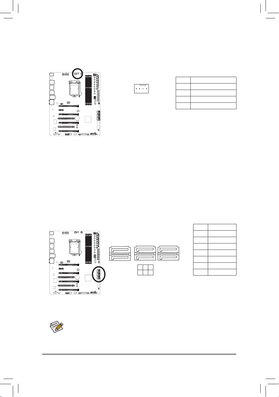
10) SPDIF_IN(S/PDIFInHeader)
This header supports digital S/PDIF In and can connect to an audio device that supports digital audio out via
an optional S/PDIF In cable. For purchasing the optional S/PDIF In cable, please contact the local dealer.
DIP
4
123
1
Pin No. Denition
1 Power
2 SPDIFI
3 GND
- 31 -
Page 32

Hardware Installation
11) SPDIF_O(S/PDIFOutHeader)
F_AUDIO(H)
DB_PORT
F_PANEL(NH) F_PANEL
(H61M-D2)
1
1
1
1
BIOS Switcher (X58A-OC)
M_SATA
F_USB30
This header supports digital S/PDIF Out and connects a S/PDIF digital audio cable (provided by expansion
cards) for digital audio output from your motherboard to certain expansion cards like graphics cards and
sound cards. For example, some graphics cards may require you to use a S/PDIF digital audio cable for
digital audio output from your motherboard to your graphics card if you wish to connect an HDMI display
to the graphics card and have digital audio output from the HDMI display at the same time.
For information about connecting the S/PDIF digital audio cable, carefully read the manual for your
expansion card.
DIP
4
123
Pin No. Denition
1 SPDIFO
1
2 GND
12) F_USB30_1/F_USB30_2(USB3.0/2.0Headers)
The header conforms to USB 3.0/2.0 specication and can provide two USB ports. For purchasing the
optional 3.5" front panel that provides two USB 3.0/2.0 ports, please contact the local dealer.
DIP
4
123
20 1
1
Pin No. Denition Pin No. Denition
1 VBUS 11 D2+
2 SSRX1- 12 D2-
3 SSRX1+ 13 GND
4 GND 14 SSTX2+
5 SSTX1- 15 SSTX2-
6 SSTX1+ 16 GND
1011
7 GND 17 SSRX2+
8 D1- 18 SSRX2-
9 D1+ 19 VBUS
10 NC 20 No Pin
10
20
Only the USB ports routed to the F_USB30_1 header can support the ON/OFF Charge2 function.
11
Prior to installing the USB front panel, be sure to turn off your computer and unplug the power cord
from the power outlet to prevent damage to the USB front panel.
- 32 -
Page 33

Hardware Installation
13) F_USB1/F_USB2(USB2.0/1.1Headers)
G.QBOFM
(H61M-D2)
ACPI_CPT
(GA-IVB)
BIOS_PH
(GA-IVB)
SMB_CPT
(GA-IVB)
CLR_CMOS
CI
DIS_ME
GP15_CPT
(GA-IVB)
XDP_CPU
XDP_PCH
(GA-IVB)
PWM Switch (SW1)(X79-UD7)
DIP
1 2 3 4 5
F_USB3 (Front Panel)
(H61M-D2)
ACPI_CPT
(GA-IVB)
BIOS_PH
(GA-IVB)
SMB_CPT
(GA-IVB)
CLR_CMOS
CI
DIS_ME
GP15_CPT
(GA-IVB)
XDP_CPU
XDP_PCH
(GA-IVB)
PWM Switch (SW1)(X79-UD7)
DIP
1 2 3 4 5
F_USB3 (Front Panel)
The headers conform to USB 2.0/1.1 specication. Each USB header can provide two USB ports via an
optional USB bracket. For purchasing the optional USB bracket, please contact the local dealer.
DIP
4
123
9
10
• Do not plug the IEEE 1394 bracket (2x5-pin) cable into the USB 2.0/1.1 header.
• Prior to installing the USB bracket, be sure to turn off your computer and unplug the power cord
from the power outlet to prevent damage to the USB bracket.
1
2
Pin No. Denition
1 Power (5V)
2 Power (5V)
3 USB DX-
4 USB DY-
5 USB DX+
6 USB DY+
7 GND
8 GND
9 No Pin
10 NC
14) F_USB3/F_USB4(USB2.0/1.1Connectors)
The two USB 2.0/1.1 ports make it easier to save data, ash the BIOS or install software in open bench
testing platforms whether for extreme overclocking or simply pretesting the PC before nal component
installation inside a case scenarios where accessing the rear panel IO can be an inconvenience.
DIP
4
123
F_USB4F_USB3
- 33 -
Page 34

Hardware Installation
15) COMA(SerialPortHeader)
The COM header can provide one serial port via an optional COM port cable. For purchasing the optional
COM port cable, please contact the local dealer.
DIP
4
123
9
10
1
2
Pin No. Denition
1 NDCD-
2 NSIN
3 NSOUT
4 NDTR-
5 GND
NDSR-
6
7 NRTS-
8 NCTS-
9 NRI-
10 No Pin
16) BAT(Battery)
The battery provides power to keep the values (such as BIOS congurations, date, and time information)
in the CMOS when the computer is turned off. Replace the battery when the battery voltage drops to a low
level, or the CMOS values may not be accurate or may be lost.
DIP
4
123
You may clear the CMOS values by removing the battery:
1. Turn off your computer and unplug the power cord.
2. Gently remove the battery from the battery holder and wait for one minute.
(Or use a metal object like a screwdriver to touch the positive and negative
terminals of the battery holder, making them short for 5 seconds.)
3. Replace the battery.
4. Plug in the power cord and restart your computer.
• Always turn off your computer and unplug the power cord before replacing the battery.
• Replace the battery with an equivalent one. Danger of explosion if the battery is replaced with
an incorrect model.
• Contact the place of purchase or local dealer if you are not able to replace the battery by yourself
or uncertain about the battery model.
• When installing the battery, note the orientation of the positive side (+) and the negative side (-)
of the battery (the positive side should face up).
• Used batteries must be handled in accordance with local environmental regulations.
- 34 -
Page 35

Hardware Installation
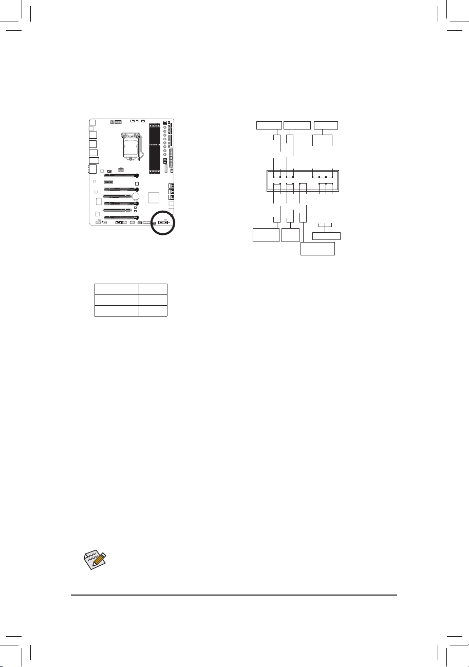
17) CLR_CMOS(ClearCMOSJumper)
Use this jumper to clear the BIOS conguration and reset the CMOS values to factory defaults. To clear
the CMOS values, use a metal object like a screwdriver to touch the two pins for a few seconds.
DIP
4
123
Open: Normal
Short: Clear CMOS Values
• Always turn off your computer and unplug the power cord from the power outlet before clearing
the CMOS values.
• After system restart, go to BIOS Setup to load factory defaults (select Load Optimized Defaults) or
manually congure the BIOS settings (refer to Chapter 2, "BIOS Setup," for BIOS congurations).
- 35 -
Page 36

Hardware Installation
- 36 -
Page 37

BIOS Setup
Chapter 2 BIOS Setup
BIOS (Basic Input and Output System) records hardware parameters of the system in the CMOS on the
motherboard. Its major functions include conducting the Power-On Self-Test (POST) during system startup,
saving system parameters and loading operating system, etc. BIOS includes a BIOS Setup program that allows
the user to modify basic system conguration settings or to activate certain system features.
When the power is turned off, the battery on the motherboard supplies the necessary power to the CMOS to
keep the conguration values in the CMOS.
To access the BIOS Setup program, press the <Delete> key during the POST when the power is turned on.
To upgrade the BIOS, use either the GIGABYTE Q-Flash or @BIOS utility.
• Q-Flash allows the user to quickly and easily upgrade or back up BIOS without entering the operating system.
• @BIOS is a Windows-based utility that searches and downloads the latest version of BIOS from the Internet
and updates the BIOS.
For instructions on using the Q-Flash and @BIOS utilities, refer to Chapter 5, "BIOS Update Utilities."
• Because BIOS ashing is potentially risky, if you do not encounter problems using the current
version of BIOS, it is recommended that you not ash the BIOS. To ash the BIOS, do it with
caution. Inadequate BIOS ashing may result in system malfunction.
• It is recommended that you not alter the default settings (unless you need to) to prevent system
instability or other unexpected results. Inadequately altering the settings may result in system's
failure to boot. If this occurs, try to clear the CMOS values and reset the board to default values.
(Refer to the "Load Optimized Defaults" section in this chapter or introductions of the battery or the
clear CMOS jumper/button in Chapter 1 for how to clear the CMOS values.)
- 37 -
Page 38

BIOS Setup
2-1 Startup Screen
The following startup Logo screen will appear when the computer boots.
Function Keys:
<DEL>: BIOS SETUP\Q-FLASH
Press the <Delete> key to enter BIOS Setup or to access the Q-Flash utility in BIOS Setup.
<F9>: SYSTEM INFORMATION
Press the <F9> key to display your system information.
<F12>: BOOT MENU
Boot Menu allows you to set the rst boot device without entering BIOS Setup. In Boot Menu, use the up
arrow key <h> or the down arrow key <i> to select the rst boot device, then press <Enter> to accept.
The system will boot from the device immediately.
Note: The setting in Boot Menu is effective for one time only. After system restart, the device boot order
will still be based on BIOS Setup settings.
<END>: Q-FLASH
Press the <End> key to access the Q-Flash utility directly without having to enter BIOS Setup rst.
- 38 -
Page 39

BIOS Setup
2-2 The Main Menu
A. Windows Mode (Default)
Differing from traditional UEFI interface, the Windows Mode provides a fancy and user-friendly BIOS environment
where users can easily point and click through various settings and make adjustments for optimum performance.
In Windows Mode, you can use your mouse to move through the option menus for quick conguration or you
can click Classic Setup under the Shortcuts list on the right of the screen or press <F2> to switch to the
traditional BIOS Setup screen.
B. Classic Setup
In Classic Setup, you can press the arrow keys on your keyboard to move among the items and press <Enter>
to accept or enter a sub-menu. Or you can use your mouse to select the item you want.
(Sample BIOS Version: F1o)
Setup Menus
Switch to
Windows
Mode
Enter Q-Flash
Select Default
Language
Conguration Items
Help
Function Keys
Current Settings
- 39 -
Page 40

BIOS Setup
Classic Setup Function Keys
<f><g>
<h><i>
<Enter> Execute command or enter a menu
<+>/<Page Up> Increase the numeric value or make changes
<->/<Page Down> Decrease the numeric value or make changes
<F2> Switch to Windows Mode
<F5> Restore the previous BIOS settings for the current submenus
<F7> Load the Optimized BIOS default settings for the current submenus
<F8> Access the Q-Flash utility
<F9> Display system information
<F10> Save all the changes and exit the BIOS Setup program
<F12> Capture the current screen as an image and save it to your USB drive
<Esc> Main Menu: Exit the BIOS Setup program
Move the selection bar to select a setup menu
Move the selection bar to select an conguration item on a menu
Submenus: Exit current submenu
BIOS Setup Menus
M.I.T.
Use this menu to congure the clock, frequency, and voltages of your CPU and memory, etc. Or check the
system/CPU temperatures, voltages, and fan speeds.
System
Use this menu to congure the default language used by the BIOS and system time and date. This menu
also displays information on the devices connected to the SATA ports.
BIOS Features
Use this menu to congure the device boot order, advanced features available on the CPU, and the primary
display adapter.
Peripherals
Use this menu to congure all peripheral devices, such as SATA, USB, integrated audio, and integrated
LAN, etc.
Power Management
Use this menu to congure all the power-saving functions.
Save & Exit
Save all the changes made in the BIOS Setup program to the CMOS and exit BIOS Setup. You can save
the current BIOS settings to a prole or load optimized defaults for optimal-performance system operations.
• When the system is not stable as usual, select the Load Optimized Defaults item to set your
system to its defaults.
• The BIOS Setup menus described in this chapter are for reference only and may differ by BIOS
version.
- 40 -
Page 41
BIOS Setup
2-3 M.I.T.
Whether the system will work stably with the overclock/overvoltage settings you made is dependent
on your overall system congurations. Incorrectly doing overclock/overvoltage may result in damage
to CPU, chipset, or memory and reduce the useful life of these components. This page is for advanced
users only and we recommend you not to alter the default settings to prevent system instability or
other unexpected results. (Inadequately altering the settings may result in system's failure to boot. If
this occurs, clear the CMOS values and reset the board to default values.)
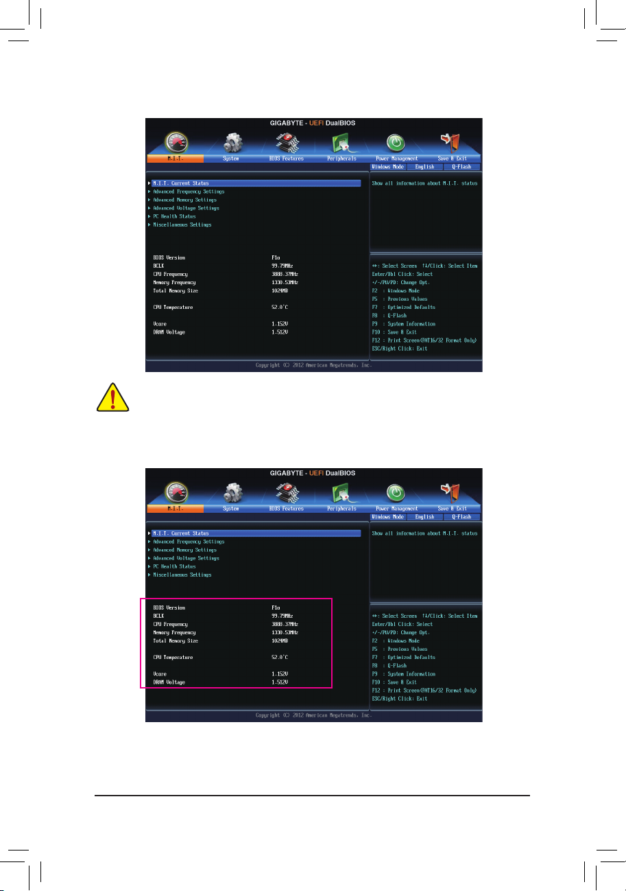
This section provides information on the BIOS version, CPU base clock, CPU frequency, memory frequency,
total memory size, CPU temperature, Vcore, and memory voltage.
- 41 -
Page 42

BIOS Setup
` M.I.T. Current Status
This screen provides information on CPU/memory frequencies/parameters.
` Advanced Frequency Settings
& CPU Base Clock
Allows you to manually set the CPU base clock in 0.01 MHz increments. (Default: Auto)
Important: It is highly recommended that the CPU frequency be set in accordance with the CPU
specications.
& Host Clock Value
Displays the current host frequency. This value is automatically adjusted according to the CPU Base Clock
settings.
& Processor Graphics Clock
Allows you to set the onboard graphics clock. The adjustable range is from 400 MHz to 4000 MHz. (Default:
Auto)
& CPU Clock Ratio
Allows you to alter the clock ratio for the installed CPU. The adjustable range is dependent on the CPU
being installed.
& CPU Frequency
Displays the current operating CPU frequency.
- 42 -
Page 43

BIOS Setup
` Advanced CPU Core Features
& CPU Clock Ratio, CPU Frequency
The settings above are synchronous to those under the same items on the Advanced Frequency Settings
menu.
& CPU PLL Selection
Allows you to set the CPU PLL. Auto lets the BIOS automatically congure this setting. (Default: Auto)
& Filter PLL Level
Allows you to set the Filter PLL. Auto lets the BIOS automatically congure this setting. (Default: Auto)
& Uncore Ratio
Allows you to set the CPU Uncore ratio. The adjustable range is dependent on the CPU being used.
& Uncore Frequency
Displays the current CPU Uncore frequency.
& Intel(R) Turbo Boost Technology
Allows you to determine whether to enable the Intel CPU Turbo Boost technology. Auto lets the BIOS
automatically congure this setting. (Default: Auto)
& Turbo Ratio (1-Core Active~4-Core Active)
Allows you to set the CPU Turbo ratios for different number of active cores. Auto sets the CPU Turbo ratios
according to the CPU specications. (Default: Auto)
(Note)
(Note)
& Turbo Power Limit (Watts)
Allows you to set a power limit for CPU Turbo mode. When the CPU power consumption exceeds the
specied power limit, the CPU will automatically reduce the core frequency in order to reduce the power.
Auto sets the power limit according to the CPU specications. (Default: Auto)
(Note) This item is present only when you install a CPU that supports this feature. For more information about
Intel® CPUs' unique features, please visit Intel's website.
- 43 -
Page 44

BIOS Setup
& Core Current Limit (Amps)
Allows you to set a current limit for CPU Turbo mode. When the CPU current exceeds the specied current
limit, the CPU will automatically reduce the core frequency in order to reduce the current. Auto sets the
power limit according to the CPU specications. (Default: Auto)
& CPU Core Enabled
Allows you to determine whether to enable all CPU cores. Auto lets the BIOS automatically congure this
setting. (Default: Auto)
& Hyper-Threading Technology
Allows you to determine whether to enable multi-threading technology when using an Intel® CPU that
supports this function. This feature only works for operating systems that support multi-processor mode.
Auto lets the BIOS automatically congure this setting. (Default: Auto)
& CPU Enhanced Halt (C1E)
Enables or disables Intel® CPU Enhanced Halt (C1E) function, a CPU power-saving function in system
halt state. When enabled, the CPU core frequency and voltage will be reduced during system halt state to
decrease power consumption. Auto lets the BIOS automatically congure this setting. (Default: Auto)
& C3/C6 State Support
Allows you to determine whether to let the CPU enter C3/C6 mode in system halt state. When enabled, the
CPU core frequency and voltage will be reduced during system halt state to decrease power consumption.
The C3/C6 state is a more enhanced power-saving state than C1. Auto lets the BIOS automatically congure
this setting. (Default: Auto)
& CPU Thermal Monitor
Enables or disables Intel® Thermal Monitor function, a CPU overheating protection function. When enabled,
the CPU core frequency and voltage will be reduced when the CPU is overheated. Auto lets the BIOS
automatically congure this setting. (Default: Auto)
& CPU EIST Function
Enables or disables Enhanced Intel® Speed Step Technology (EIST). Depending on CPU loading, Intel
EIST technology can dynamically and effectively lower the CPU voltage and core frequency to decrease
average power consumption and heat production. Auto lets the BIOS automatically congure this setting.
(Default: Auto)
(Note 1)
(Note 1)
(Note 1)
(Note 1)
(Note 1)
(Note 1)
& Extreme Memory Prole (X.M.P.)
(Note 2)
Allows the BIOS to read the SPD data on XMP memory module(s) to enhance memory performance when
enabled.
Disabled Disables this function. (Default)
Prole1 Uses Prole 1 settings.
(Note 2)
Prole2
Uses Prole 2 settings.
& System Memory Multiplier
Allows you to set the system memory multiplier. Auto sets memory multiplier according to memory SPD
data. (Default: Auto)
& Memory Frequency (MHz)
The rst memory frequency value is the normal operating frequency of the memory being used; the second
is the memory frequency that is automatically adjusted according to the System Memory Multiplier settings.
(Note 1) This item is present only when you install a CPU that supports this feature. For more information about
Intel® CPUs' unique features, please visit Intel's website.
(Note 2) This item is present only when you install a CPU and a memory module that support this feature.
- 44 -
Page 45

BIOS Setup
` Advanced Memory Settings
& Extreme Memory Prole (X.M.P.)
(Note)
, System Memory Multiplier, Memory
Frequency(MHz)
The settings above are synchronous to those under the same items on the Advanced Frequency Settings
menu.
& Performance Enhance
Allows the system to operate at three different performance levels.
Normal Lets the system operate at its basic performance level.
Turbo Lets the system operate at its good performance level. (Default)
Extreme Lets the system operate at its best performance level.
& DRAM Timing Selectable
Quick and Expert allows the Channel Interleaving, Rank Interleaving, and memory timing settings below
to be congurable. Options are: Auto (default), Quick, Expert.
& Prole DDR Voltage
When using a non-XMP memory module or Extreme Memory Prole (X.M.P.) is set to Disabled, this item
will display as 1.50V. When Extreme Memory Prole (X.M.P.) is set to Prole1 or Prole2, this item will
display the value based on the SPD data on the XMP memory.
& Channel Interleaving
Enables or disables memory channel interleaving. Enabled allows the system to simultaneously access
different channels of the memory to increase memory performance and stability. Auto lets the BIOS
automatically congure this setting. (Default: Auto)
& Rank Interleaving
Enables or disables memory rank interleaving. Enabled allows the system to simultaneously access different
ranks of the memory to increase memory performance and stability. Auto lets the BIOS automatically
congure this setting. (Default: Auto)
(Note) This item is present only when you install a CPU and a memory module that support this feature.
- 45 -
Page 46

BIOS Setup
` Channel A/B Timing Settings
This sub-menu provides memory timing settings for each channel of memory. The respective timing setting
screens are congurable only when DRAM Timing Selectable is set to Quick or Expert. Note: Your system
may become unstable or fail to boot after you make changes on the memory timings. If this occurs, please reset
the board to default values by loading optimized defaults or clearing the CMOS values.
` Advanced Voltage Settings
- 46 -
Page 47

BIOS Setup
` 3D Power Control
& CPU VRIN Loadline Calibration
Allows you to set the Load-Line Calibration level for the CPU VRIN. The levels are (from highest to lowest):
Extreme, Turbo, High, Medium, Low, and Standard. Selecting a higher level keeps the CPU VRIN voltage
more consistent with what is set in BIOS under heavy load. Auto lets the BIOS automatically congure
this setting and sets the voltage following Intel's specications. (Default: Auto)
& CPU VRIN Protection
Allows you to set the over-current protection level for the CPU VRIN voltage. The adjustable range is from
150.0mV to 500.0mV. Auto lets the BIOS automatically congure this setting. (Default: Auto)
& DDR CH(A/B) Voltage Protection
Allows you to set the voltage limit on Channel A and Channel B memory voltage for over-voltage protection.
The adjustable range is from 150.0mV to 300.0mV. Auto lets the BIOS automatically congure this setting.
(Default: Auto)
& CPU VRIN Current Protection
Allows you to set the over-current protection level for the CPU VRIN voltage.
Auto Lets BIOS automatically congure this setting. (Default)
Standard~Extreme Selects Standard, Low, Medium, High, Turbo, or Extreme which represents different
level of over-current protection for the CPU VRIN voltage.
& DDR CH(A/B) Current Protection
Allows you to set the over-current protection level for the memory voltage.
Auto Lets BIOS automatically congure this setting. (Default)
Standard~Extreme Selects Standard, Low, Medium, High, Turbo, or Extreme which represents different
level of over-current protection for the memory voltage.
- 47 -
Page 48
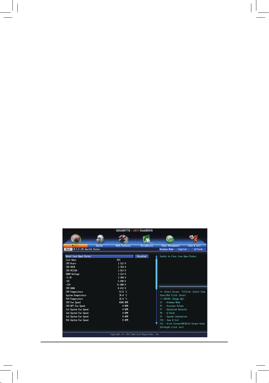
BIOS Setup
& CPU VRIN PWM Thermal Protection
Displays the PWM thermal protection threshold for the CPU VRIN area.
& DDR CH(A/B) PWM Thermal Protection
Displays the PWM thermal protection threshold for the Channel A and Channel B memory area.
& CPU VRIN PWM Switch Rate
Displays the CPU VRIN PWM frequency. (Default: Auto)
& DDR CH(A/B) PWM Switch Rate
Displays the current operating PWM frequency for Channel A and Channel B memory. (Default: Auto)
& PWM Phase Control
Allows you to automatically change the PWM phase according to the CPU load. The power-saving
levels are (from lowest to highest): eXm Perf (Extreme Performance ), High Perf (High Performance),
Perf (Performance), Balanced, Mid PWR (Mid Power), and Lite PWR (Light Power). Auto lets the BIOS
automatically congure this setting. (Default: Auto)
` CPU Core Voltage Control
This section provides CPU voltage control options.
` Chipset Voltage Control
This section provides Chipset voltage control options.
` DRAM Voltage Control
This section provides memory voltage control options.
` PC Health Status
- 48 -
Page 49

BIOS Setup
& Reset Case Open Status
Disabled Keeps or clears the record of previous chassis intrusion status. (Default)
Enabled Clears the record of previous chassis intrusion status and the Case Open eld will show
"No" at next boot.
& Case Open
Displays the detection status of the chassis intrusion detection device attached to the motherboard CI
header. If the system chassis cover is removed, this eld will show "Yes", otherwise it will show "No". To
clear the chassis intrusion status record, set Reset Case Open Status to Enabled, save the settings to
the CMOS, and then restart your system.
& CPU Vcore/CPU VRIN/CPU VCCIOA/DRAM Voltage/+3.3V/+5V/+12V/CPU VAXG
Displays the current system voltages.
& CPU/System/PCH Temperature
Displays current CPU/Chipset/System temperature.
& CPU/CPU OPT/System Fan Speed
Displays current CPU/CPU_OPT/system fan speeds.
& CPU/System Warning Temperature
Sets the warning threshold for CPU/system temperature. When CPU/system temperature exceeds
the threshold, BIOS will emit warning sound. Options are: Disabled (default), 60oC/140oF, 70oC/158oF,
80oC/176oF, 90oC/194oF.
& CPU/CPU OPT/System Fan Fail Warning
Allows the system to emit warning sound if the fan is not connected or fails. Check the fan condition or fan
connection when this occurs. (Default: Disabled)
& CPU Fan Speed Control (CPU_FAN Connector)
Allows you to determine whether to enable the fan speed control function and adjust the fan speed.
Normal Allows the fan to run at different speeds according to the CPU temperature. You can adjust
the fan speed with EasyTune based on your system requirements. (Default)
Silent Allows the fan to run at slow speeds.
- 49 -
Page 50

BIOS Setup
Manual Allows you to control the fan speed under the Slope PWM item.
Disabled Allows the fan to run at full speeds.
& Slope PWM
Allows you to control the fan speed. This item is congurable only when CPU Fan Speed Control is set
to Manual. Options are: 0.75 PWM value /oC ~ 2.50 PWM value /oC.
& CPU OPT Fan Speed Control (CPU_OPT Connector)
Allows you to determine whether to enable the fan speed control function and adjust the fan speed.
Normal Allows the fan to run at different speeds according to the CPU temperature. You can adjust
the fan speed with EasyTune based on your system requirements. (Default)
Silent Allows the fan to run at slow speeds.
Manual Allows you to control the fan speed under the Slope PWM item.
Disabled Allows the fan to run at full speeds.
& Slope PWM
Allows you to control the fan speed. This item is congurable only when CPU OPT Fan Speed Control is
set to Manual. Options are: 0.75 PWM value /oC ~ 2.50 PWM value /oC.
& 1st System Fan Speed Control (SYS_FAN1 Connector)
Allows you to determine whether to enable the fan speed control function and adjust the fan speed.
Normal Allows the fan to run at different speeds according to the system temperature. You can adjust
the fan speed with EasyTune based on your system requirements. (Default)
Silent Allows the fan to run at slow speeds.
Manual Allows you to control the fan speed under the Slope PWM item.
Disabled Allows the fan to run at full speeds.
& Slope PWM
Allows you to control the fan speed. This item is congurable only when 1st System Fan Speed Control
is set to Manual. Options are: 0.75 PWM value /oC ~ 2.50 PWM value /oC.
& 2nd System Fan Speed Control (SYS_FAN2 Connector)
Allows you to determine whether to enable the fan speed control function and adjust the fan speed.
Normal Allows the fan to run at different speeds according to the system temperature. (Default)
Silent Allows the fan to run at slow speeds.
Manual Allows you to control the fan speed under the Slope PWM item.
Disabled Allows the fan to run at full speeds.
& Slope PWM
Allows you to control the fan speed. This item is congurable only when 2nd System Fan Speed Control
is set to Manual. Options are: 0.75 PWM value /oC ~ 2.50 PWM value /oC.
& 3rd System Fan Speed Control (SYS_FAN3 Connector)
Allows you to determine whether to enable the fan speed control function and adjust the fan speed.
Normal Allows the fan to run at different speeds according to the system temperature. (Default)
Silent Allows the fan to run at slow speeds.
Manual Allows you to control the fan speed under the Slope PWM item.
Disabled Allows the fan to run at full speeds.
& Slope PWM
Allows you to control the fan speed. This item is congurable only when 3rd System Fan Speed Control
is set to Manual. Options are: 0.75 PWM value /oC ~ 2.50 PWM value /oC.
- 50 -
Page 51

BIOS Setup
& 4th/5th System Fan Speed Control (SYS_FAN4 and SYS_FAN5 Connectors)
Allows you to determine whether to enable the fan speed control function and adjust the fan speed.
Normal Allows the fan to run at different speeds according to the system temperature. (Default)
Silent Allows the fan to run at slow speeds.
Manual Allows you to control the fan speed under the Slope PWM item.
Disabled Allows the fan to run at full speeds.
& Slope PWM
Allows you to control the fan speed. This item is congurable only when 4th/5th System Fan Speed
Control is set to Manual. Options are: 0.75 PWM value /oC ~ 2.50 PWM value /oC.
` Miscellaneous Settings
& PEG Gen3 Slot Conguration
Allows you to set the operation mode of the PCI Express slots to Gen 1, Gen 2, or Gen 3. Actual operation
mode is subject to the hardware specication of each slot. For example, the PCI Express x1 slots can
support up to Gen 2 mode only. Auto lets the BIOS automatically congure this setting. (Default: Auto)
& Legacy BenchMark Enhancement
Allows you to determine whether to enhance some legacy benchmark performance. (Default: Disabled)
- 51 -
Page 52

BIOS Setup
2-4 System
This section provides information on your CPU, memory, motherboard model, and BIOS version. You can also
select the default language used by the BIOS and manually set the system time.
& System Language
Selects the default language used by the BIOS.
& System Date
Sets the system date. The date format is week (read-only), month, date, and year. Use <Enter> to switch
between the Month, Date, and Year elds and use the <Page Up> or <Page Down> key to set the desired
value.
& System Time
Sets the system time. The time format is hour, minute, and second. For example, 1 p.m. is 13:0:0. Use
<Enter> to switch between the Hour, Minute, and Second elds and use the <Page Up> or <Page Down>
key to set the desired value.
& Access Level
Displays the current access level depending on the type of password protection used. (If no password is
set, the default will display as Administrator.) The Administrator level allows you to make changes to all
BIOS settings; the User level only allows you to make changes to certain BIOS settings but not all.
- 52 -
Page 53

BIOS Setup
2-5 BIOS Features
& Boot Option Priorities
Species the overall boot order from the available devices. For example, you can set hard drive as the
rst priority (Boot Option #1) and DVD ROM drive as the second priority (Boot Option #2). The list only
displays the device with the highest priority for a specic type. For example, only hard drive dened as the
rst priority on the Hard Drive BBS Priorities submenu will be presented here.
Removable storage devices that support GPT format will be prexed with "UEFI:" string on the boot device
list. To boot from an operating system that supports GPT partitioning, select the device prexed with "UEFI:"
string.
Or if you want to install an operating system that supports GPT partitioning such as Windows 7 64-bit, select
the optical drive that contains the Windows 7 64-bit installation disk and is prexed with "UEFI:" string.
- 53 -
Page 54

BIOS Setup
& Hard Drive/CD/DVD ROM Drive/Floppy Drive/Network Device BBS Priorities
Species the boot order for a specic device type, such as hard drives, optical drives, oppy disk drives,
and devices that support Boot from LAN function, etc. Press <Enter> on this item to enter the submenu that
presents the devices of the same type that are connected. This item is present only if at least one device
for this type is installed.
& Bootup NumLock State
Enables or disables Numlock feature on the numeric keypad of the keyboard after the POST. (Default:
Enabled)
& Security Option
Species whether a password is required every time the system boots, or only when you enter BIOS Setup.
After conguring this item, set the password(s) under the Administrator Password/User Password item.
Setup A password is only required for entering the BIOS Setup program.
System A password is required for booting the system and for entering the BIOS Setup
program. (Default)
& Full Screen LOGO Show
Allows you to determine whether to display the GIGABYTE Logo at system startup. Disabled skips the
GIGABYTE Logo when the system starts up. (Default: Enabled)
& Fast Boot
Enables or disables Fast Boot to shorten the OS boot process. Ultra Fast provides the fastest bootup
speed. (Default: Disabled)
& Limit CPUID Maximum
(Note)
Allows you to determine whether to limit CPUID maximum value. Set this item to Disabled for Windows XP
operating system; set this item to Enabled for legacy operating system such as Windows NT4.0. (Default:
Disabled)
& Execute Disable Bit
(Note)
Enables or disables Intel® Execute Disable Bit function. This function may enhance protection for the
computer, reducing exposure to viruses and malicious buffer overow attacks when working with its
supporting software and system. (Default: Enabled)
& Intel Virtualization Technology
(Note)
Enables or disables Intel® Virtualization Technology. Virtualization enhanced by Intel® Virtualization
Technology will allow a platform to run multiple operating systems and applications in independent partitions.
With virtualization, one computer system can function as multiple virtual systems. (Default: Enabled)
& Intel TXT(LT) Support
(Note)
Enables or disables Intel® Trusted Execution Technology (Intel® TXT). Intel® Trusted Execution Technology
provides a hardware-based security foundation. (Default: Disabled)
& Dynamic Storage Accelerator
Enables or disables Intel® Dynamic Storage Accelerator. When enabled, the hard drive I/O performance
will be adjusted according to hard drive load. (Default: Disabled)
(Note)
& VT-d
Enables or disables Intel® Virtualization Technology for Directed I/O. (Default: Enabled)
& OS Type
Allows you to select the operating system to be installed. (Default: Other OS)
& CSM Support
Enables or disables UEFI CSM (Compatibility Support Module) to support a legacy PC boot process.
(Note) This item is present only when you install a CPU that supports this feature. For more information about
Intel® CPUs' unique features, please visit Intel's website.
- 54 -
Page 55

BIOS Setup
Always Enables UEFI CSM. (Default)
Never Disables UEFI CSM and supports UEFI BIOS boot process only.
This item is congurable only when OS Type is set to Windows 8 or Windows 8 WHQL.
& Boot Mode Selection
Allows you to select which type of operating system to boot.
UEFI and Legacy Allows booting from operating systems that support legacy option ROM or UEFI
option ROM. (Default)
Legacy Only Allows booting from operating systems that only support legacy Option ROM.
UEFI Only Allows booting from operating systems that only support UEFI Option ROM.
This item is congurable only when CSM Support is set to Always.
& LAN PXE Boot Option ROM
Allows you to select whether to enable the legacy option ROM for the LAN controller. (Default: Disabled)
This item is congurable only when CSM Support is set to Always.
& Storage Boot Option Control
Allows you to select whether to enable the UEFI or legacy option ROM for the storage device controller.
Disabled Disables option ROM.
Legacy only Enables legacy option ROM only. (Default)
UEFI only Enables UEFI option ROM only.
Legacy First Enables legacy option ROM rst.
UEFI First Enables UEFI option ROM rst.
This item is congurable only when CSM Support is set to Always.
& Other PCI Device ROM Priority
Allows you to select whether to enable the UEFI or Legacy option ROM for the PCI device controller other
than the LAN, storage device, and graphics controllers.
Legacy OpROM Enables legacy option ROM only.
UEFI OpROM Enables UEFI option ROM only. (Default)
& Network stack
Disables or enables booting from the network to install a GPT format OS, such as installing the OS from
the Windows Deployment Services server. (Default: Disabled)
& Ipv4 PXE Support
Enables or disables IPv4 PXE Support. This item is congurable only when Network stack is enabled.
& Ipv6 PXE Support
Enables or disables IPv6 PXE Support. This item is congurable only when Network stack is enabled.
& Administrator Password
Allows you to congure an administrator password. Press <Enter> on this item, type the password, and
then press <Enter>. You will be requested to conrm the password. Type the password again and press
<Enter>. You must enter the administrator password (or user password) at system startup and when entering
BIOS Setup. Differing from the user password, the administrator password allows you to make changes to
all BIOS settings.
& User Password
Allows you to congure a user password. Press <Enter> on this item, type the password, and then press
<Enter>. You will be requested to conrm the password. Type the password again and press <Enter>.
You must enter the administrator password (or user password) at system startup and when entering BIOS
Setup. However, the user password only allows you to make changes to certain BIOS settings but not all.
To cancel the password, press <Enter> on the password item and when requested for the password, enter the
correct one rst. When prompted for a new password, press <Enter> without entering any password. Press
<Enter> again when prompted to conrm.
- 55 -
Page 56

BIOS Setup
2-6 Peripherals
& Init Display First
Specifes the frst initiation of the monitor display from the installed PCI graphics card, PCI Express graphics
card, or the onboard graphics.
IGFX Sets the onboard graphics as the rst display.
PCIe 1 Slot Sets the graphics card on the PCIEX16 slot as the rst display.(Default)
PCIe 2 Slot Sets the graphics card on the PCIEX4_1 slot as the rst display.
PCIe 3 Slot Sets the graphics card on the PCIEX8 slot as the rst display.
PCIe 4 Slot Sets the graphics card on the PCIEX4_2 slot as the rst display.
PCI Sets the graphics card on the PCI as the rst display.
& PCH LAN Controller
Enables or disables the onboard LAN function. (Default: Enabled) If you wish to install a 3rd party add-in
network card instead of using the onboard LAN, set this item to Disabled.
& XHCI Mode (Intel® Z87 Chipset)
Allows you to determine the operating mode for the xHCI controller in OS.
Smart Auto This mode is available only when the BIOS supports the xHCI controller in the pre-boot
environment. This mode is similar to Auto, but it adds the capability to route the ports
to xHCI or EHCI according to setting used in previous boots (for non-G3 boot) in the
pre-boot environment. This allows the use of USB 3.0 devices prior to OS boot. xHCI
controller enabling and rerouting should follow the steps in Auto, when previous boot
routs ports to EHCI. Note: This is the recommended mode when BIOS has xHCI preboot support.(Default)
Auto BIOS routes the sharable ports to EHCI controller. Then it uses ACPI protocols to
provide an option to enable the xHCI controller and reroute the sharable ports. Note:
This is the recommended mode when BIOS does NOT have xHCI pre-boot support.
- 56 -
Page 57

BIOS Setup
Enabl ed All shared ports are eventually routed to the xHCI controller during the BIOS boot process.
If BIOS does not have pre-boot support for the xHCI controller, it should initially route
the sharable ports to the EHCI controller and then prior to OS boot it should route the
ports to xHCI controller. Note: OS has to provide support for the xHCI controller in this
mode. If the OS does not provide support, all sharable ports won't work.
Disabled The USB 3.0 ports are routed to the EHCI controller and the xHCI controller is turned
off. All USB 3.0 devices function as High Speed devices regardless of xHCI software
support/availability.
Manual Allows you to determine whether to rout the USB 3.0 ports to the xHCI or EHCI controller
before booting to OS, and also provides you with options to manually rout each USB
3.0/2.0 port to xHCI or EHCI.
& Audio Controller
Enables or disables the onboard audio function. (Default: Auto)
If you wish to install a 3rd party add-in audio card instead of using the onboard audio, set this item to
Disabled.
& Internal Graphics
Enables or disables the onboard graphics function. (Default: Enabled)
& Internal Graphics Memory Size
Allows you to set the onboard graphics memory size. Options are: 32M~1024M. (Default: 64M)
& DVMT Total Memory Size
Allows you to allocate the DVMT memory size of the onboard graphics. Options are: 128M, 256M, MAX.
(Default: MAX)
& Intel(R) Rapid Start Technology
Enables or disables Intel® Rapid Start Technology. (Default: Disabled)
& Legacy USB Support
Allows USB keyboard/mouse to be used in MS-DOS. (Default: Enabled)
& XHCI Hand-off
Determines whether to enable XHCI Hand-off feature for an operating system without XHCI Hand-off
support. (Default: Enabled)
& EHCI Hand-off
Determines whether to enable EHCI Hand-off feature for an operating system without EHCI Hand-off
support. (Default: Disabled)
& USB Storage Devices
Displays a list of connected USB mass storage devices. This item appears only when a USB storage device
is installed.
& PCIE Slot Conguration
Species the operating bandwidth for the PCIEX4_1 slot.
Auto Lets the BIOS automatically congure this setting depending on the expansion card being installed.
(Default)
x4 PCIEX4_1 operates at x4 mode.
- 57 -
Page 58

BIOS Setup
` SATA Conguration
& SATA Controller(s)
Enables or disables the integrated SATA controllers. (Default: Enabled)
& SATA Mode Selection
Enables or disables RAID for the SATA controllers or congures the SATA controllers to AHCI mode.
IDE Congures the SATA controller to IDE mode.
RAID Enables RAID for the SATA controller.
AHCI Congures the SATA controllers to AHCI mode. Advanced Host Controller Interface
(AHCI) is an interface specication that allows the storage driver to enable advanced
Serial ATA features such as Native Command Queuing and hot plug. (Default)
` Serial ATA Port 0/1/2/3/4/5
& Port 0/1/2/3/4/5
Enables or disables each SATA port. (Default: Enabled)
& Hot plug
Enables or disable the hot plug capability for each SATA port. (Default: Disabled)
- 58 -
Page 59

BIOS Setup
` Super IO Conguration
This section provides information on the super I/O chip and allows you to congure the serial port.
& Serial Port A
Enables or disables the onboard serial port. (Default: Enabled)
` Intel(R) Smart Connect Technology
& ISCT Support
Enables or disables Intel® Smart Connect Technology. (Default: Disabled)
` Intel(R) Ethernet Network Connection i217V
This sub-menu provides information on LAN conguration and related conguration options.
- 59 -
Page 60

BIOS Setup
2-7 Power Management
& Resume by Alarm
Determines whether to power on the system at a desired time. (Default: Disabled)
If enabled, set the date and time as following:
Wake up day: Turn on the system at a specic time on each day or on a specic day in a month.
Wake up hour/minute/second: Set the time at which the system will be powered on automatically.
Note: When using this function, avoid inadequate shutdown from the operating system or removal of the
AC power, or the settings may not be effective.
& Wake on LAN
Enables or disables the wake on LAN function. (Default: Enabled)
& ErP
Determines whether to let the system consume least power in S5 (shutdown) state. (Default: Disabled)
Note: When this item is set to Enabled, the following functions will become unavailable: PME event wake
up, power on by mouse, power on by keyboard, and wake on LAN.
& Soft-Off by PWR-BTTN
Congures the way to turn off the computer in MS-DOS mode using the power button.
Instant-Off Press the power button and then the system will be turned off instantly. (Default)
Delay 4 Sec Press and hold the power button for 4 seconds to turn off the system. If the power
button is pressed for less than 4 seconds, the system will enter suspend mode.
& RC6(Render Standby)
Allows you to determine whether to let the onboard graphics enter standby mode to decrease power
consumption. (Default: Enabled)
& AC BACK
Determines the state of the system after the return of power from an AC power loss.
Always Off The system stays off upon the return of the AC power. (Default)
Always On The system is turned on upon the return of the AC power.
Memory The system returns to its last known awake state upon the return of the AC power.
- 60 -
Page 61

BIOS Setup
& Power On By Keyboard
Allows the system to be turned on by a PS/2 keyboard wake-up event.
Note: To use this function, you need an ATX power supply providing at least 1A on the +5VSB lead.
Disabled Disables this function. (Default)
Any Key Press any key to turn on the system.
Keyboard 98 Press POWER button on the Windows 98 keyboard to turn on the system.
Password Set a password with 1~5 characters to turn on the system.
& Power On Password
Set the password when Power On by Keyboard is set to Password.
Press <Enter> on this item and set a password with up to 5 characters and then press <Enter> to accept.
To turn on the system, enter the password and press <Enter>.
Note: To cancel the password, press <Enter> on this item. When prompted for the password, press <Enter>
again without entering the password to clear the password settings.
& Power On By Mouse
Allows the system to be turned on by a PS/2 mouse wake-up event.
Note: To use this function, you need an ATX power supply providing at least 1A on the +5VSB lead.
Disabled Disables this function. (Default)
Move Move the mouse to turn on the system.
Double Click Double click on left button on the mouse to turn on the system.
- 61 -
Page 62

BIOS Setup
2-8 Save & Exit
& Save & Exit Setup
Press <Enter> on this item and select Yes. This saves the changes to the CMOS and exits the BIOS Setup
program. Select No or press <Esc> to return to the BIOS Setup Main Menu.
& Exit Without Saving
Press <Enter> on this item and select Yes. This exits the BIOS Setup without saving the changes made
in BIOS Setup to the CMOS. Select No or press <Esc> to return to the BIOS Setup Main Menu.
& Load Optimized Defaults
Press <Enter> on this item and select Yes to load the optimal BIOS default settings. The BIOS defaults
settings help the system to operate in optimum state. Always load the Optimized defaults after updating
the BIOS or after clearing the CMOS values.
& Boot Override
Allows you to select a device to boot immediately. Press <Enter> on the device you select and select Yes
to conrm. Your system will restart automatically and boot from that device.
& Save Proles
This function allows you to save the current BIOS settings to a prole. You can create up to 8 proles and
save as Setup Prole 1~ Setup Prole 8. Press <Enter> to complete. Or you can select Select File in
HDD/USB/FDD to save the prole to your storage device.
& Load Proles
If your system becomes unstable and you have loaded the BIOS default settings, you can use this function
to load the BIOS settings from a prole created before, without the hassles of reconguring the BIOS
settings. First select the prole you wish to load and then press <Enter> to complete. You can select Select
File in HDD/USB/FDD to input the prole previously created from your storage device or load the prole
automatically created by the BIOS, such as reverting the BIOS settings to the last settings that worked
properly (last known good record).
- 62 -
Page 63

Conguring SATA Hard Drive(s)
Chapter 3 Conguring SATA Hard Drive(s)
RAID Levels
Minimum
Number of Hard
Drives
Array Capacity Number of hard
Fault Tolerance No Yes Yes Yes
To congure SATA hard drive(s), follow the steps below:
A. Install SATA hard drive(s) in your computer.
B. Congure SATA controller mode in BIOS Setup.
C. Congure a RAID array in RAID BIOS.
D. Install the SATA RAID/AHCI driver and operating system.
Before you begin
Please prepare:
• At least two SATA hard drives (to ensure optimal performance, it is recommended that you use two hard drives
with identical model and capacity). If you do not want to create RAID, you may prepare only one hard drive.
• Windows 8/7 setup disk.
• Motherboard driver disk.
• A USB thumb drive
RAID 0 RAID 1 RAID 5 RAID 10
≥2 2 ≥3 ≥4
drives * Size of the
smallest drive
Size of the smallest
drive
(Note 1)
(Number of hard
drives -1) * Size of
the smallest drive
(Note 2)
(Number of hard
drives/2) * Size of the
smallest drive
3-1 Conguring SATA Controllers
A. Installing SATA hard drive(s) in your computer
Attach one end of the SATA signal cable to the rear of the SATA hard drive and the other end to available SATA
port on the motherboard. Then connect the power connector from your power supply to the hard drive.
(Note 1) Skip this step if you do not want to create RAID array on the SATA controller.
(Note 2) Required when the SATA controller is set to AHCI or RAID mode.
- 63 -
Page 64

Conguring SATA Hard Drive(s)
B. Conguring SATA controller mode in BIOS Setup
Make sure to congure the SATA controller mode correctly in system BIOS Setup.
Step 1:
Turn on your computer and press <Delete> to enter BIOS Setup during the POST (Power-On Self-Test). Go to
Peripherals\SATA Conguration, make sure SATA Controllers is enabled. To create RAID, set SATA Mode
Selection to RAID (Figure 1). If you do not want to create RAID, set this item to IDE or AHCI.
Figure 1
Step 2:
If you want to congure UEFI RAID, follow the steps in "C-1." To enter the legacy RAID ROM, save the settings
and exit BIOS Setup. Refer to "C-2" for more information.
The BIOS Setup menus described in this section may differ from the exact settings for your motherboard.
The actual BIOS Setup menu options you will see shall depend on the motherboard you have and
the BIOS version.
- 64 -
Page 65

Conguring SATA Hard Drive(s)
C-1. UEFI RAID Conguration
This mode supports Windows 8 64-bit installation only.
Step 1:
In BIOS Setup, go to BIOS Features and set OS Type to Windows 8 and CSM Support to Never. (Figure 2)
Save the changes and exit BIOS Setup.
Step 2:
After the system reboot, enter BIOS Setup again. Then enter the Peripherals\Intel(R) Rapid Storage Technology
sub-menu (Figure 3).
Figure 2
Figure 3
- 65 -
Page 66

Conguring SATA Hard Drive(s)
Step 3:
On the Intel(R) Rapid Storage Technology menu, press <Enter> on Create RAID Volume to enter the Create
RAID Volume screen. Enter a volume name with 1~16 letters (letters cannot be special characters) under the
Name item and press <Enter>. Then, select a RAID level (Figure 4). RAID levels supported include RAID 0,
RAID 1, RAID 10, and RAID 5 (the selections available depend on the number of the hard drives being installed).
Next, use the down arrow key to move to Select Disks.
Step 4:
Under Select Disks item, select the hard drives to be included in the RAID array. Press the <Space> key on
the hard drives to be selected (selected hard drives are marked with "X"). Then set the stripe block size (Figure
5). The stripe block size can be set from 4 KB to 128 KB. Once you have selected the stripe block size, set
the volume capacity.
Figure 4
Figure 5
- 66 -
Page 67

Conguring SATA Hard Drive(s)
Step 5:
After setting the capacity, move to Create Volume and press <Enter> to begin. (Figure 6)
Figure 6
After completing, you'll be brought back to the Intel(R) Rapid Storage Technology screen. Under RAID Volumes
you can see the new RAID volume. To see more detailed information, press <Enter> on the volume to check
for information on RAID level, stripe block size, array name, and array capacity, etc. (Figure 7)
Figure 7
- 67 -
Page 68

Conguring SATA Hard Drive(s)
Delete RAID Volume
To delete a RAID array, press <Enter> on the volume to be deleted on the Intel(R) Rapid Storage Technology
screen. After entering the RAID VOLUME INFO screen, press <Enter> on Delete to enter the Delete screen.
Press <Enter> on Yes (Figure 8).
Figure 8
- 68 -
Page 69

Conguring SATA Hard Drive(s)
C-2. Conguring Legacy RAID ROM
Enter the Intel® legacy RAID BIOS setup utility to congure a RAID array. Skip this step and proceed with the
installation of Windows operating system for a non-RAID conguration.
Step 1:
After the POST memory test begins and before the operating system boot begins, look for a message which says
"Press <Ctrl-I> to enter Conguration Utility" (Figure 9). Press <Ctrl> + <I> to enter the RAID Conguration Utility.
Intel(R) Rapid Storage Technology - Option ROM - 12.0.0.1783
Copyright(C) 2003-13 Intel Corporation. All Rights Reserved.
RAID Volumes :
None dened.
Physical Devices :
ID Device Model Serial # Size Type/Status(Vol ID)
0 ST3120026AS 3JT354CP 111.7GB Non-RAID Disk
1 ST3120026AS 3JT329JX 111.7GB Non-RAID Disk
Press <CTRL - I> to enter Conguration Utility..
Figure 9
Step 2:
After you press <Ctrl> + <I>, the MAIN MENU screen will appear (Figure 10).
Create RAID Volume
If you want to create a RAID array, select Create RAID Volume in MAIN MENU and press <Enter>.
1. Create RAID Volume
2. Delete RAID Volume
3. Reset Disks to Non-RAID
Intel(R) Rapid Storage Technology - Option ROM - 12.0.0.1783
Copyright(C) 2003-13 Intel Corporation. All Rights Reserved.
[ MAIN MENU ]
4. Recovery Volume Options
5. Acceleration Options
6. Exit
[ DISK/VOLUME INFORMATION ]
RAID Volumes :
None dened.
Physical Deivces :
ID Device Model Serial # Size Type/Status(Vol ID)
0 ST3120026AS 3JT354CP 111.7GB Non-RAID Disk
1 ST3120026AS 3JT329JX 111.7GB Non-RAID Disk
[hi]-Select [ESC]-Exit [ENTER]-Select Menu
Figure 10
- 69 -
Page 70

Conguring SATA Hard Drive(s)
Step 3:
After entering the CREATE VOLUME MENU screen, enter a volume name with 1~16 letters (letters cannot be
special characters) under the Name item and press <Enter>. Then, select a RAID level (Figure 11). RAID levels
supported include RAID 0, RAID 1, RAID 10, and RAID 5 (the selections available depend on the number of the
hard drives being installed). Press <Enter> to proceed.
Intel(R) Rapid Storage Technology - Option ROM - 12.0.0.1783
Copyright(C) 2003-13 Intel Corporation. All Rights Reserved.
Name : Volume0
RAID Level : RAID0(Stripe)
Disks : Select Disks
Strip Size : 128KB
Capacity : 111.7 GB
Sync : N/A
Create Volume
[hi]-Change [TAB]-Next [ESC]-Previous Menu [ENTER]-Select
[ CREATE VOLUME MENU ]
[ HELP ]
RAID0: Stripes data (performance).
Figure 11
Step 4:
Under Disks item, select the hard drives to be included in the RAID array. If only two hard drives are installed,
they will be automatically assigned to the array. Set the stripe block size (Figure 12) if necessary. The stripe block
size can be set from 4 KB to 128 KB. Once you have selected the stripe block size, press <Enter>.
Intel(R) Rapid Storage Technology - Option ROM - 12.0.0.1783
Copyright(C) 2003-13 Intel Corporation. All Rights Reserved.
Name : Volume0
RAID Level : RAID0(Stripe)
Disks : Select Disks
Strip Size : 128KB
Capacity : 111.7 GB
Sync : N/A
Create Volume
The following are typical values:
RAID0 - 128KB
RAID10 - 64KB
RAID5 - 64KB
[ CREATE VOLUME MENU ]
[ HELP ]
[hi]-Change [TAB]-Next [ESC]-Previous Menu [ENTER]-Select
Figure 12
- 70 -
Page 71

Conguring SATA Hard Drive(s)
Step 5:
Enter the array capacity and press <Enter>. Finally press <Enter> on the Create Volume item to begin creating
the RAID array. When prompted to conrm whether to create this volume, press <Y> to conrm or <N> to
cancel (Figure 13).
Intel(R) Rapid Storage Technology - Option ROM - 12.0.0.1783
Copyright(C) 2003-13 Intel Corporation. All Rights Reserved.
Name : Volume0
RAID Level : RAID0(Stripe)
Disks : Select Disks
Strip Size : 128 MB
Capacity : 111.7 GB
Sync : N/A
Create Volume
[hi]-Change [TAB]-Next [ESC]-Previous Menu [ENTER]-Select
WARNING : ALL DATA ON SELECTED DISKS WILL BE LOST.
[ CREATE VOLUME MENU ]
[ HELP ]
Are you sure you want to create this volume? (Y/N) :
Press ENTER to create the specied volume.
Figure 13
When completed, you can see detailed information about the RAID array in the DISK/VOLUME INFORMATION
section, including the RAID level, stripe block size, array name, and array capacity, etc. (Figure 14)
Intel(R) Rapid Storage Technology - Option ROM - 12.0.0.1783
Copyright(C) 2003-13 Intel Corporation. All Rights Reserved.
1. Create RAID Volume
2. Delete RAID Volume
3. Reset Disks to Non-RAID
[ MAIN MENU ]
4. Recovery Volume Options
5. Acceleration Options
6. Exit
[ DISK/VOLUME INFORMATION ]
RAID Volumes :
ID Name Level Strip Size Status Bootable
0 Volume0 RAID0(Stripe) 128KB 223.6GB Normal Yes
Physical Devices :
ID Device Model Serial # Size Type/Status(Vol ID)
0 ST3120026AS 3JT354CP 111.7GB Member Disk(0)
1 ST3120026AS 3JT329JX 111.7GB Member Disk(0)
[hi]-Select [ESC]-Exit [ENTER]-Select Menu
Figure 14
To exit the RAID BIOS utility, press <Esc> or select 6. Exit in MAIN MENU.
Now, you can proceed to install the SATA RAID/AHCI driver and operating system.
- 71 -
Page 72

Conguring SATA Hard Drive(s)
Recovery Volume Options
Intel® Rapid Recover Technology provides data protection by allowing users to easily restore data and system
operation using a designated recovery drive. With the Rapid Recovery Technology, which employs RAID 1
functionality, users can copy the data from the master drive to the recovery drive; if needed, the data on the
recovery drive can be restored back to the master drive.
Before you begin:
• The recovery drive must have equal or greater capacity than the master drive.
• A recovery volume can be created with two hard drives only. A recovery volume and a RAID array cannot
co-exist in the system at the same time, that is, if you have already created a recovery volume, you are
unable to create a RAID array.
• By default, only the master drive can be viewed in the operating system; the recovery drive is hidden.
Step 1:
Select Create RAID Volume in MAIN MENU and press <Enter> (Figure 15).
Intel(R) Rapid Storage Technology - Option ROM - 12.0.0.1783
Copyright(C) 2003-13 Intel Corporation. All Rights Reserved.
1. Create RAID Volume
2. Delete RAID Volume
3. Reset Disks to Non-RAID
RAID Volumes :
None dened.
Physical Disks :
IE Drive Model Serial # Size Type/Status(Vol ID)
0 ST3120026AS 3JT354CP 111.7GB Non-RAID Disk
1 ST3120026AS 3JT329JX 111.7GB Non-RAID Disk
[ MAIN MENU ]
[ DISK/VOLUME INFORMATION ]
4. Recovery Volume Options
5. Acceleration Options
6. Exit
[hi]-Select [ESC]-Exit [ENTER]-Select Menu
Figure 15
Step 2:
After entering the volume name, select Recovery under the RAID Level item and press <Enter> (Figure 16).
Intel(R) Rapid Storage Technology - Option ROM - 12.0.0.1783
Copyright(C) 2003-13 Intel Corporation. All Rights Reserved.
Name : Volume0
RAID Level : Recovery
Disks : Select Disks
Strip Size : N/A
Capacity : 111.7 GB
Sync : Continuous
Create Volume
Recovery: Copies data between a master and a recovery disk.
[hi]-Change [TAB]-Next [ESC]-Previous Menu [ENTER]-Select
[ CREATE VOLUME MENU ]
[ HELP ]
Figure 16
- 72 -
Page 73

Conguring SATA Hard Drive(s)
Step 3:
Press <Enter> under the Select Disks item. In the SELECT DISKS box, press <Tab> on the hard drive you want
to use for the master drive and press <Space> on the hard drive you want to use for the recovery drive. (Make sure
the recovery drive has equal or larger capacity than the master drive.) Then press <Enter> to conrm (Figure 17).
Intel(R) Rapid Storage Technology - Option ROM - 12.0.0.1783
Copyright(C) 2003-13 Intel Corporation. All Rights Reserved.
Name : Volume0
RAID Level : Recovery
Disks : Select Disks
Strip Size : 128KB
Capacity : 223.6 GB
ID Drive Model Serial # Size Status
Create Volume
M0 ST3120026AS 3JT354CP 111.7GB Non-RAID Disk
R1 ST3120026AS 3JT329JX 111.7GB Non-RAID Disk
Select 1 Master and 1 Recovery disk to create volume.
[hi]-Change [TAB]-Next [ESC]-Previous Menu [ENTER]-Select
Recovery: Copies data between a master and a recovery disk.
[hi]-Prev/Next [TAB]-(M)aster [SPACE]-(R)ecovery [ENTER]-Done
[ CREATE VOLUME MENU ]
[ SELECT DISKS ]
[ HELP ]
Choose the RAID level:
RAID0: Stripes data (performance).
RAID1: Mirrors data (redundancy).
RAID10: Mirrors data and stripes the mirror.
RAID5: Stripes data and parity.
Figure 17
Step 4:
Under Sync, select Continuous or On Request (Figure 18). When set to Continuous, changes made to the
data on the master drive will be automatically and continuously copied to the recovery drive when both hard
drives are installed in the system. On Request allows users to update data from the master drive to the recovery
drive manually using the Intel® Rapid Storage Technology utility in the operating system. On Request also allows
users to restore the master drive to a previous state.
Intel(R) Rapid Storage Technology - Option ROM - 12.0.0.1783
Copyright(C) 2003-13 Intel Corporation. All Rights Reserved.
Name : Volume0
RAID Level : Recovery
Disks : Select Disks
Strip Size : N/A
Capacity : 0.0 GB
Sync : Continuous
Create Volume
[ CREATE VOLUME MENU ]
[ HELP ]
Select a sync option:
On Request: volume is updated manually
Continuous: volume is updated automatically
[hi]-Change [TAB]-Next [ESC]-Previous Menu [ENTER]-Select
Figure 18
Step 5:
Finally press <Enter> on the Create Volume item to begin creating the Recovery Volume and follow the on-
screen instructions to complete.
- 73 -
Page 74
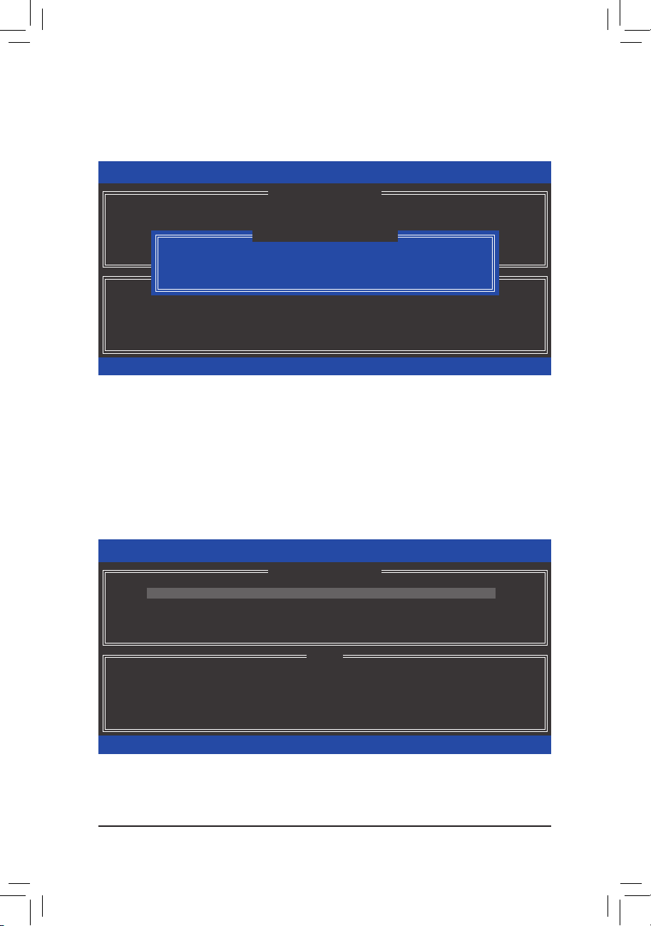
Conguring SATA Hard Drive(s)
Delete RAID Volume
To delete a RAID array, select Delete RAID Volume in MAIN MENU and press <Enter>. In the DELETE
VOLUME MENU section, use the up or down arrow key to select the array to be deleted and press <Delete>.
When prompted to conrm your selection (Figure 19), press <Y> to conrm or <N> to abort.
Intel(R) Rapid Storage Technology - Option ROM - 12.0.0.1783
Copyright(C) 2003-13 Intel Corporation. All Rights Reserved.
Name Level Drives Capacity Status Bootable
Volume0 RAID0(Stripe) 2 223.6GB Normal Yes
[hi]-Select [ESC]-Exit [DEL]-Delete Volume
[ DELETE VOLUME MENU ]
[ DELETE VOLUME VERIFICATION ]
ALL DATA IN THE VOLUME WILL BE LOST!
(This does not apply to Recovery volumes)
Are you sure you want to delete "Volume0"? (Y/N) :
Deleting a volume will reset the disks to non-RAID.
WARNING: ALL DISK DATA WILL BE DELETED.
(This does not apply to Recovery volumes)
[ HELP ]
Figure 19
Acceleration Options
This option allows you to view the status of your accelerated drive/volume (Figure 20) created using the Intel®
IRST utility. In case you are unable to run the Intel® IRST utility due to an application error or operating system
issue, you will need to remove acceleration or manually enable synchronization (Maximized mode only) using
this option in the RAID ROM utility.
Steps:
Select Acceleration Options in MAIN MENU and press <Enter>.
To remove the acceleration, select the accelerated drive/volume, press <R>, and press <Y> to conrm.
To synchronize data from the cache device to the accelerated drive/volume, press <S> and press <Y> to conrm.
Intel(R) Rapid Storage Technology - Option ROM - 12.0.0.1783
Copyright(C) 2003-13 Intel Corporation. All Rights Reserved.
Name Type Capacity Mode Status
DISK PORT 3 Non-RAID Disk 74.5GB Enhanced In Sync
[ ACCELERATION OPTIONS ]
WARNING: IT IS RECOMMENDED THAT YOU PERFORM A SYNCHRONIZATION
[hi]-Select [ESC]- Previous Menu
[ HELP ]
Press 's' to synchronize data from the cache device to
the Accelerated Disk/Volume
Press 'r' to remove the Disk/Volume Acceleration
BEFORE REMOVING ACCELERATION
Figure 20
- 74 -
Page 75

Conguring SATA Hard Drive(s)
3-2 Installing the SATA RAID/AHCI Driver and Operating System
With the correct BIOS settings, you are ready to install Windows 8/7.
A. Installing Windows 8/7
As Windows 7 already include Intel® SATA RAID/AHCI driver, you do not need to install separate RAID/AHCI
driver during the Windows installation process. After the operating system is installed, we recommend that you
install all required drivers from the motherboard driver disk using "Xpress Install" to ensure system performance
and compatibility. To install Windows 8, refer to the steps below:
Step 1:
Copy the IRST folder under BootDrv in the driver disk to your USB thumb drive.
Step 2:
Boot from the Windows 8 setup disk and perform standard OS installation steps. When the screen requesting
you to load the driver appears, select Browse.
Step 3:
Insert the USB thumb drive and then browse to the location of the driver. The locations of the drivers are as follows:
Windows 32-bit: \iRST\32Bit
Windows 64-bit: \iRST\64Bit
Step 4:
When a screen as shown in Figure 1 appears, select Intel(R) Desktop/Workstation/Server Express Chipset
SATA RAID Controller and click Next to load the driver and continue the OS installation
Figure 1
- 75 -
Page 76

Conguring SATA Hard Drive(s)
B. Rebuilding an Array
Rebuilding is the process of restoring data to a hard drive from other drives in the array. Rebuilding applies only
to fault-tolerant arrays such as RAID 1, RAID 5 or RAID 10 arrays. The procedures below assume a new drive
is added to replace a failed drive to rebuild a RAID 1 array. (Note: The new drive must have equal or greater
capacity than the old one.)
Turn off your computer and replace the failed hard drive with a new one. Restart your computer.
• Enabling Automatic Rebuild
Step 1:
When the message "Press <Ctrl-I> to enter Conguration Utility" appears, press <Ctrl> + <I> to enter the RAID
Conguration Utility. The following screen appears after you enter the RAID Conguration Utility.
Intel(R) Rapid Storage Technology - Option ROM - 12.0.0.1783
Copyright(C) 2003-13 Intel Corporation. All Rights Reserved.
[ MAIN MENU ]
1. Create RAID Volume
2. Delete RAID Volume
"Degraded volume and disk available for rebuilding detected. Selecting
a disk initiates a rebuild. Rebuild completes in the operating system.
Select the port of the destination disk for rebuilding (ESC to exit):
RAID Volumes :
ID Drive Model Serial # Size
None dened.
1 WDC WD800JD-22LS WD-WMAM9W736333 111.7GB
Physical Disks :
ID Drive Model Serial # Size Type/Status(Vol ID)
0 ST3120026AS 3JT354CP 111.7GB Member Disk (0)
1 WDC WD800JD-22LS WD-WMAM9W736333 111.7GB Non-RAID Disk
[hi]-Select [ESC]-Exit [ENTER]-Select Menu
[hi]-Previous/Next [ENTER]-Select [ESC]-Exit
[ DEGRADED VOLUME DETECTED ]
[ DISK/VOLUME INFORMATION ]
Step 2:
Select the new hard drive to add into the array to be rebuilt and press <Enter>. The following screen appears,
indicating that an automatic rebuild will be performed after you enter the operating system. If you do not enable
automatic rebuild on this stage, you have to manually rebuild the array in the operating system (see the next
page for more details).
Intel(R) Rapid Storage Technology - Option ROM - 12.0.0.1783
Copyright(C) 2003-13 Intel Corporation. All Rights Reserved.
1. Create RAID Volume
2. Delete RAID Volume
3. Reset Disks to Non-RAID
[ MAIN MENU ]
3. Reset Disks to Non-RAID
4. Exit
4. Recovery Volume Options
5. Acceleration Options
6. Exit
RAID Volumes :
ID Name Level Strip Size Status Bootable
0 Volume0 RAID1(Mirror) N/A 111.7GB Rebuild Ye s
Physical Devices :
ID Devices Model Serial # Size Type/Status(Vol ID)
0 ST3120026AS 3JT354CP 111.7GB Member Disk (0)
1 WDC WD800JD-22LS WD-WMAM9W736333 111.7GB Member Disk (0)
[hi]-Select [ESC]-Exit [ENTER]-Select Menu
[ DISK/VOLUME INFORMATION ]
Volumes with "Rebuild" status will be rebuilt within the operating system.
- 76 -
Page 77

Conguring SATA Hard Drive(s)
• Performing the Rebuild in the Operating System
While in the operating system, make sure the chipset driver has been installed from the motherboard driver
disk. Then launch the Intel® Rapid Storage Technology utility from the desktop.
Step 2:
Select a new drive to rebuild the RAID and click
Rebuild.
Step 1:
Go to the Manage menu and click Rebuild to
another disk in Manage Volume.
The Status item on the left of the screen displays
the rebuild progress.
Step 3:
After the RAID 1 volume rebuilding, the Status will
display as Normal.
- 77 -
Page 78

Conguring SATA Hard Drive(s)
• Restoring the Master Drive to a Previous State (for Recovery Volume only)
When two hard drives are set to Recovery Volume in Update on Request mode, you can restore the master
drive data to the last backup state when needed. For example, in case the master drive detects a virus, you
can restore the recovery drive data to the master drive.
Step 1:
Select 4. Recovery Volume Options in the MAIN MENU of the Intel® RAID Conguration Utility. On the
RECOVERY VOLUMES OPTIONS menu, select Enable Only Recovery Disk to show the recovery drive in
the operating system. Follow the on-screen instructions to complete and exit the RAID Conguration Utility.
Intel(R) Rapid Storage Technology - Option ROM - 12.0.0.1783
Copyright(C) 2003-13 Intel Corporation. All Rights Reserved.
[ RECOVERY VOLUME OPTIONS ]
1. Enable Only Recovery Disk
2. Enable Only Master Disk
[ SELECT RECOVERY VOLUME ]
Name Level Capacity Status Bootable
Volume0 Recovery(OnReq) 111.7GB NeedsUpdate Yes
}
Select a Recovery volume to do the operation.
[hi]-select [ESC]-Previous Menu [ENTER]-Select
Recovery: Copies data between a master and a recovery disk.
RAID10: Mirrors data and stripes the mirror.
[hi]-Up/Down [SPACE]-Selects [ENTER]-Done
[ HELP ]
Choose the RAID level:
RAID0: Stripes data (performance).
RAID1: Mirrors data (redundancy).
RAID5: Stripes data and parity.
Step 2:
Go to the Manage menu of the Intel® Rapid
Storage Technology utility and click Recover data
in Manage Volume.
The Status item on the left of the screen displays
the rebuild progress.
Step 3:
Click Yes to begin the data recovery.
Step 4:
After the recovery volume is completed, the Status
will display as Normal.
- 78 -
Page 79

Drivers Installation
Chapter 4 Drivers Installation
• Before installing the drivers, rst install the operating system. (The following instructions use
Windows 8 as the example operating system.)
• After installing the operating system, insert the motherboard driver disk into your optical drive.
Click on the message "Tap to choose what happens with this disc" on the top-right corner of the
screen and select "Run Run.exe." (Or go to My Computer, double-click the optical drive and execute the Run.exe program.)
4-1 Chipset Drivers
"Xpress Install" will automatically scan your system and then list all of the drivers that are recommended to
install. You can click the Xpress Install button and "Xpress Install" will install all of the selected drivers. Or
click the arrow icon to individually install the drivers you need.
• Please ignore the popup dialog box(es) (e.g. the Found New Hardware Wizard) displayed
when "Xpress Install" is installing the drivers. Failure to do so may affect the driver installation.
• Some device drivers will restart your system automatically during the driver installation. After the
system restart, "Xpress Install" will continue to install other drivers.
- 79 -
Page 80

Drivers Installation
4-2 Application Software
This page displays the apps that GIGABYTE develops and some free software. You can select the apps you
want and click the Install icon to begin the installation.
4-3 Information
This page provides detailed information on the drivers on the driver disk. The Contact page provides contact
information of the GIGABYTE Taiwan headquarter. You can click the URL on this page to link to the GIGABYTE website to check more information on the GIGABYTE headquarter or worldwide branch ofces.
- 80 -
Page 81

Unique Features
Chapter 5 Unique Features
5-1 BIOS Update Utilities
GIGABYTE motherboards provide two unique BIOS update tools, Q-Flash™ and @BIOS™. GIGABYTE Q-Flash
and @BIOS are easy-to-use and allow you to update the BIOS without the need to enter MS-DOS mode.
Additionally, this motherboard features the DualBIOS™ design, which enhances protection for the safety and
stability of your computer by adding one more physical BIOS chip.
What is DualBIOS™?
Motherboards that support DualBIOS have two BIOS onboard, a main BIOS and a backup BIOS. Normally, the
system works on the main BIOS. However, if the main BIOS is corrupted or damaged, the backup BIOS will
take over on the next system boot and copy the BIOS le to the main BIOS to ensure normal system operation.
For the sake of system safety, users cannot update the backup BIOS manually.
What is Q-Flash™?
With Q-Flash you can update the system BIOS without having to enter operating systems like MS-DOS or
Window rst. Embedded in the BIOS, the Q-Flash tool frees you from the hassles of going through complicated
BIOS ashing process.
What is @BIOS™?
@BIOS allows you to update the system BIOS while in the Windows environment. @BIOS will download the
latest BIOS le from the nearest @BIOS server site and update the BIOS.
5-1-1 Updating the BIOS with the Q-Flash Utility
A. Before You Begin
1. From GIGABYTE's website, download the latest compressed BIOS update le that matches your motherboard
model.
2. Extract the le and save the new BIOS le (e.g.Z87XOC.F1) to your USB ash drive or hard drive. Note: The
USB ash drive or hard drive must use FAT32/16/12 le system.
3. Restart the system. During the POST, press the <End> key to enter Q-Flash. Note: You can access Q-Flash
by either pressing the <End> key during the POST or pressing the <F8> key in BIOS Setup. However, if the
BIOS update le is saved to a hard drive in RAID/AHCI mode or a hard drive attached to an independent
SATA controller, use the <End> key during the POST to access Q-Flash.
Because BIOS ashing is potentially risky, please do it with caution. Inadequate BIOS ashing may
result in system malfunction.
- 81 -
Page 82

Unique Features
B. Updating the BIOS
In the main menu of Q-Flash, use the keyboard or mouse to select an item to execute. When updating the
BIOS, choose the location where the BIOS le is saved. The following procedure assumes that you save the
BIOS le to a USB ash drive.
Step 1:
1. Insert the USB ash drive containing the BIOS le into the computer. In the main menu of Q-Flash, select
Update BIOS From Drive.
• The Save BIOS to Drive option allows you to save the current BIOS le.
• Q-Flash only supports USB ash drive or hard drives using FAT32/16/12 le system.
• If the BIOS update le is saved to a hard drive in RAID/AHCI mode or a hard drive attached to
an independent SATA controller, use the <End> key during the POST to access Q-Flash.
2. Select USB Flash Drive.
Model Name : Z87X-OC
BIOS Version : F1l
BIOS Date : 04/02/2013
Flash Type/Size : MXIC 25L Series 16MB
3. Select the BIOS update le.
Make sure the BIOS update le matches your motherboard model.
Q-Flash Utility v1.05
Update BIOS From Drive
USB Flash Drive
Save BIOS to Drive
Select Device
Return to BIOS setup
Step 2:
The process of the system reading the BIOS le from the USB ash drive is displayed on the screen. When
the message "Are you sure to update BIOS?" appears, select Yes to begin the BIOS update. The monitor will
display the update process.
• Do not turn off or restart the system when the system is reading/updating the BIOS.
• Do not remove the USB ash drive or hard drive when the system is updating the BIOS.
Step 3:
The system will restart after the update process is complete.
- 82 -
Page 83

Unique Features
Step 4:
During the POST, press <Delete> to enter BIOS Setup. Select Load Optimized Defaults on the Save & Exit
screen and press <Enter> to load BIOS defaults. System will re-detect all peripheral devices after a BIOS update,
so we recommend that you reload BIOS defaults.
Select Yes to load BIOS defaults
Step 5:
Select Save & Exit Setup and press <Enter>. And then select Yes to save settings to CMOS and exit BIOS
Setup. The procedure is complete after the system restarts.
- 83 -
Page 84

Unique Features
5-1-2 Updating the BIOS with the @BIOS Utility
A. Before You Begin
1. In Windows, close all applications and TSR
(Terminate and Stay Resident) programs. This
helps prevent unexpected failures when performing
a BIOS update.
2. If the BIOS is being updated via the Internet, ensure
the Internet connection is stable and do NOT
interrupt the Internet connection (for example, avoid
a power loss or switching off the Internet). Failure to
do so may result in a corrupted BIOS or a system
that is unable to start.
3. GIGABYTE product warranty does not cover any
BIOS damage or system failure resulting from an inadequate BIOS ashing.
B. Using @BIOS
1. Update the BIOS Using the Internet Update Function:
2. Update the BIOS without Using the Internet Update Function:
Click Update from Server, select the @BIOS server site closest to your location and
then download the BIOS le that matches your motherboard model. Follow the on-screen
instructions to complete.
If the BIOS update le for your motherboard is not present on the @BIOS server site, please
manually download the BIOS update le from GIGABYTE's website and follow the instructions in
"Update the BIOS without Using the Internet Update Function" below.
Click Update from le, then select the location where you save the BIOS update le obtained
from the Internet or through other source. Follow the on-screen instructions to complete.
3. Save the Current BIOS File:
Click Save to le to save the current BIOS le.
4. Change the Boot-up Logo:
Click Upload new image in Face-Wizard and you will be able to change the boot-up logo
with your own picture, creating a personalized boot-up screen. Click Backup current image
to save the currently used boot-up logo.
Supported image formats include jpg, bmp, and gif.
C. After Updating the BIOS
Restart your system after updating the BIOS.
• Make sure that the BIOS le to be ashed matches your motherboard model. Updating the BIOS
with an incorrect BIOS le could cause your system not to boot.
• Do not turn off the system or remove the power during the BIOS update process, or the BIOS may
corrupt and the system may not boot.
- 84 -
Page 85

Unique Features
5-2 APP Center
GIGABYTE App Center gives you easy access to a wealth of GIGABYTE apps that help you get the most from
your GIGABYTE motherboard
to easily launch all GIGABYTE apps installed on your system, check related udpates online, and download the
apps, drivers, and BIOS.
(Note)
. Using a simple, unied user interface, GIGABYTE App Center allows you
Running the APP Center
Insert the motherboard driver disk. On the Autorun screen, go to Application Software\Install GIGABYTE
Utilities to install GIGABYTE App Center and the selected apps. Restart your computer after the installation
is complete. In Desktop mode, click the App Center icon in the notication area to launch the App Center
utility (Figure 1). On the main menu, you can select an app to run or click Live Update to update an app online.
Figure 1
If the App Center is closed, you can restart it by clicking the App Center icon on the Start menu. (Figure 2)
Figure 2
(Note) Available applications in APP Center may differ by motherboard model. Supported functions of each
application may also differ depending on motherboard specications.
- 85 -
Page 86

Unique Features
5-2-1 EasyTune
GIGABYTE's EasyTune is a simple and easy-to-use interface that allows users to ne-tune their system settings
or do overclock/overvoltage in Windows environment. The user-friendly EasyTune interface also includes tabbed
pages for CPU and memory information, letting users read their system-related information without the need
to install additional software.
The EasyTune Interface
Tabs Information
Tab Function
The System Information tab provides information on the installed CPU and motherboard.
Smart Quick Boost provides you with different levels of CPU frequency to choose to achieve
desired system performance. After making changes, be sure to restart your system for these
changes to take effect. The Advanced menu allows you to change specic clock/frequency/
votlage settings.
The Smart Fan tab allows you to specify a Smart Fan mode. The Calibrate menu displays
the detected linear fan speed for the fans on the motherboard from the fastest to the slowest.
The Advanced menu allows you to set temperature thresholds, based on which the fan speed
can be changed linearly.
The System Alerts tab allows you to monitor hardware temperature, voltage and fan speed
and set temperature/fan speed alarm.
The 3D Power tab allows you to change power phase and voltage settings.
Available functions in EasyTune may differ by motherboard model. Grayed-out area(s) indicates that
the item is not congurable or the function is not supported.
Incorrectly doing overclock/overvoltage may result in damage to the hardware components such
as CPU, chipset, and memory and reduce the useful life of these components. Before you do the
overclock/overvoltage, make sure that you fully know each function of EasyTune, or system instability
or other unexpected results may occur.
- 86 -
Page 87

Unique Features
5-2-2 EZ Setup
The GIGABYTE EZ Setup utility includes the following 'EZ' setups applications that will offer greatly simplied
install and conguration procedures: Disk Mode Switch, EZ Smart Response, EZ Rapid Start, EZ Smart
Connect, and XHD.
Disk Mode Switch
Disk Mode Switch allows you to switch the operating mode for your hard drive even after it's been installed with
an operating system. Supported operating modes include IDE, AHCI, and RAID. You can select a disk mode
and restart your computer after the selection.
• Native UEFI mode is not supported.
• Be sure to reinstall the Intel® Rapid Storage Technology utility after you switch the disk mode.
- 87 -
Page 88

Unique Features
EZ Smart Response
A. System Requirements
1. An Intel® Chipset-based motherboard supporting this feature
2. Intel® Core series processor
3. Intel® SATA controller set to RAID mode
4. Intel® Rapid Storage Technology utility installed
5. A conventional SATA disk and an SSD
6. Windows 7 with SP1/Windows 8
(Note 3)
(Note 1)
(Note 2)
If you have installed the operating system before conguring the Smart Response Technology, all
original data on the SSD will be lost once you enable RAID mode
back up the hard disk before enabling the Smart Response Technology.
(Note 1)
(Note 4)
. It is recommended that you
B. Using EZ Smart Response
Select EZ Smart Response and click Create.
To disable this function, click Delete.
(Note 1) Before start, make sure you have installed the Intel® Rapid Storage Technology utility (version 11.5 or
above).
(Note 2) The SSD works as a cache of the hard disk. The maximum cache memory size is 64 GB. If you use
an SSD larger than 64 GB, the space beyond 64 GB can still be used for storing your data.
(Note 3) The operating system must be installed to the SATA disk.
(Note 4) Regardless of the BIOS settings, be it IDE or AHCI mode, the system will be forced into RAID mode.
- 88 -
Page 89

Unique Features
EZ Rapid Start
A. System Requirements
1. Intel® Rapid Start Technology enabled in BIOS Setup
2. An SSD with size larger than the total system memory
3. Windows 7 with SP1/Windows 8
4. AHCI/RAID mode supported (please note if the SSD has been assigned as a member of a RAID array, it
cannot be used to set up and Intel® Rapid Start store partition); IDE mode not supported
(Note)
B. Using EZ Rapid Start
Select EZ Rapid Start and click Create. Then install the Intel® Rapid Start Technology utility and restart your
computer to complete.
To disable this function, click Delete.
• The default compressed space is the system memory size plus 2 GB. For example, if the system
memory size is 8 GB, the default compressed space is 8 GB plus 2 GB, so the SSD capacity will
decrease by 10 GB. If EZ Rapid Start is disabled, the decreased 10 GB will be returned to the SSD.
• If you want to upgrade your system memory, disable EZ Rapid Start rst and re-install it to ensure
it can work normally.
(Note) If the motherboard Chipset supports RAID, EZ Rapid Start will force the Intel® SATA controllers into
RAID mode. If not, the Intel® SATA controllers will be forced into AHCI mode.
- 89 -
Page 90

Unique Features
EZ Smart Connect
A. System Requirements
1. Intel® Smart Connect Technology enabled in BIOS Setup
2. Windows 7 with SP1/Windows 8
3. Intel® Smart Connect Technology utility installed
4. Properly-working network connection
5. Programs added to the White List must be turned on
(Note)
B. Using EZ Smart Connect
Select EZ Smart Connect. Under File Name, select the apps to be auto-updated by Smart Connect. Double-
click the app to add it to the Application permission list. (Double-click to return to the previous directory.)
(Note) This feature works best with programs designed to work automatically with the Internet to obtain their
data such as Outlook®, Windows Live™ Mail, and Seesmic®.
- 90 -
Page 91

Unique Features
XHD
With GIGABYTE XHD
(Note 1)
, users can quickly congure a RAID-ready system for RAID 0 or RAID 1 when a
new SATA drive is added. All with a simple click of a button, XHD helps to enhance your hard drive read/write
performance without the need for complex and time-consuming congurations. .
A. System Requirements
1. An Intel® Chipset motherboard supporting RAID
2. Intel® SATA controllers set to RAID mode
3. Intel® Rapid Storage Technology utility installed
4. Windows 7 with SP1/Windows 8
5. Intel® SATA controller driver installed
B. Using XHD
Select XHD and click Create RAID 0 or Create RAID 1 based on your need.
(Note 2)
(Note 1) The XHD utility only supports the SATA connectors controlled by the Intel® Chipset.
(Note 2) Except for the operating system drive, all data on other hard drive will be deleted. Back up your data
before using the XHD utility.
- 91 -
Page 92

Unique Features
5-2-3 ON/OFF Charge2
GIGABYTE ON/OFF Charge2 Technology can automatically detect your mobile device such as smart phone
and tablet PC and quickly charge the device through USB interface. It provides the best charging solution while
the system is turned on, in sleep/standby mode, or even turned off.
The ON/OFF Charge2 Interface
Using ON/OFF Charge2
ON/OFF Charge2 automatically detects your mobile device and displays it on the screen. Available functions
may vary by device. If your mobile device does not support data sync, select Fast Charge/No Sync to enable
a quick charge.
• Fast Charge:
Automatically detects mobile device(s) and enables both quick charge and data sync.
• Fast Charge/No Sync:
Automatically detects mobile device(s) and enables a quick charge but no data sync.
• Rescan:
Rescan the connected mobile device(s).
• Exit:
Turn off ON/OFF Charge2.
- 92 -
Page 93

Unique Features
5-2-4 USB Blocker
GIGABYTE USB Blocker provides you with an easy-to-use interface that allows you to block certain USB device
types on your PC. Devices classes that are blocked will be ignored by the operating system.
The USB Blocker Interface
Using USB Blocker
Select the class of USB device that you would like to block or unblocked. Double left-click to change the Blocked
or Unblocked status and click OK. Then enter your password and click OK to complete.
- 93 -
Page 94

Unique Features
- 94 -
Page 95

Appendix
Chapter6 Appendix
6-1 ConguringAudioInputandOutput
6-1-1 Conguring2/4/5.1/7.1-ChannelAudio
The motherboard provides six audio jacks on the back
panel which support 2/4/5.1/7.1-channel
The picture to the right shows the default audio jack
assignments.
The integrated HD (High Denition) audio provides
jack retasking capability that allows the user to change
the function for each jack through the audio driver.
(Supported functions for each jack may vary based on
hardware specication.)
• To install a microphone, connect your microphone to the Mic in jack and manually congure the
jack for microphone functionality.
• Audio signals will be present on both of the front and back panel audio connections simultaneously.
If you want to mute the back panel audio (only supported when using an HD front panel audio
module), refer to instructions on the next page.
HighDenitionAudio(HDAudio)
HD Audio includes multiple high quality digital-to-analog converters (DACs). HD Audio features multistreaming
capabilities that allow multiple audio streams (in and out) to be simultaneously processed. For example, users can
listen to MP3 music, have an Internet chat, make a telephone call over the Internet, and etc. all at the same time.
A.ConguringSpeakers
(The following instructions use Windows 8 as the example operating system.)
(Note)
audio.
Center/Subwoofer
Speaker Out
Rear Speaker Out Front Speaker Out
Side
Speaker Out
Line In
Mic In
Step 1:
After installing the audio driver, the HDAudioManager
icon will appear in the notication area. Double-click
the icon to access the HDAudioManager.
(Note) 2/4/5.1/7.1-Channel Audio Congurations:
Refer to the following for multi-channel speaker congurations.
• 2-channel audio: Headphone or Line out.
• 4-channel audio: Front speaker out and Rear speaker out.
• 5.1-channel audio: Front speaker out, Rear speaker out, and Center/Subwoofer speaker out.
• 7.1-channel audio: Front speaker out, Rear speaker out, Center/Subwoofer speaker out, and Side speaker out.
- 95 -
Page 96

Appendix
Step 2:
Connect an audio device to an audio jack. The Thecurrent
connecteddeviceis dialog box appears. Select the device
according to the type of device you connect. Then click OK.
Step 3:
On the Speakers screen, click the SpeakerConguration
tab. In the SpeakerConfiguration list, select Stereo,
Quadraphonic, 5.1Speaker, or 7.1Speaker according to
the type of speaker conguration you wish to set up. Then
the speaker setup is completed.
B.ConguringSoundEffect
You may congure an audio environment on the SoundEffects tab.
C.ActivatinganAC'97FrontPanelAudioModule
If your chassis provides an AC'97 front panel audio module,
to activate the AC'97 functionality, click the tool icon on the
SpeakerConguration tab. On the Connector Settings
dialog box, select the Disablefrontpaneljackdetection
check box. Click OK to complete.
D.MutingtheBackPanelAudio(ForHDAudioOnly)
Click Deviceadvancedsettings on the top right corner
on the SpeakerConguration tab to open the Device
advancedsettings dialog box. Select the Mutetherear
outputdevice,whenafrontheadphonepluggedin check
box. Click OK to complete.
- 96 -
Page 97

Appendix
6-1-2 ConguringS/PDIFIn/Out
A.S/PDIFIn
The S/PDIF In cable (optional) allows you to input digital audio signals to the computer for audio processing.
1.ConnectingaS/PDIFInCable:
Connect a S/PDIF in cable to the SPDIF_IN header on the motherboard as shown below.
DIP
4
123
2.ConguringS/PDIFIn:
On the DigitalInput screen, click the DefaultFormat tab and then select the sample rate and bit depth. Click
OK to complete.
- 97 -
Page 98

Appendix
B.S/PDIFOut
The S/PDIF Out jack can transmit audio signals to an external decoder for decoding to get the best audio quality.
1.ConnectingaS/PDIFOutCable:
Connect a S/PDIF optical cable to the corresponding S/PDIF out connector as shown below and an external
decoder for transmitting the S/PDIF digital audio signals.
Connects to a S/PDIF optical cable
2.ConguringS/PDIFOut:
On the DigitalOutput(Optical) screen
(Note)
, click the DefaultFormat tab and then select the sample rate and
bit depth. Click OK to complete.
(Note) Enter the Digital Output(Optical) screen to congure further settings if you use the S/PDIF Out
connector(s) on the back panel for digital audio output or enter the Digital Outputscreen if you use
the internal S/PDIF Out connector (SPDIF_O) for digital audio output.
- 98 -
Page 99

Appendix
6-1-3 ConguringMicrophoneRecording
Step 1:
After installing the audio driver, the HDAudioManager
icon will appear in the notication area. Double-click
the icon to access the HDAudioManager.
Step 2:
Connect your microphone to the Mic in jack (pink) on the
back panel or the Mic in jack (pink) on the front panel.
Then congure the jack for microphone functionality.
Note: The microphone functions on the front panel and
back panel cannot be used at the same time.
Step 3:
Go to the Microphone screen. Do not mute the recording
volume, or you'll not be able to record the sound. To hear
the sound being recorded during the recording process,
do not mute the playback volume. It is recommended that
you set the volumes at a middle level.
Step 4:
To raise the recording and playback volume for the
microphone, click the MicrophoneBoost icon on
the right of the RecordingVolume slider and set the
Microphone Boost level.
- 99 -
Page 100

Appendix
Step 5:
To open the SounderRecorder, move the mouse cursor
to the bottom left corner of the screen, click the Start
icon to switch to the Start screen (or press the Windows
button on the keyboard). Right-click on the screen and
click the Allapps icon on the bottom right corner of
the screen to access the Apps screen
Step 6:
On this screen, click SoundRecorder for audio recording.
*EnablingStereoMix
If the HD Audio Manager does not display the recording device you wish to use, refer to the steps below. The
following steps explain how to enable Stereo Mix (which may be needed when you want to record sound from
your computer).
Step 1:
Locate the icon in the notication area and right-click
on this icon. Select RecordingDevices.
- 100 -
 Loading...