

GIGABYTE GA-H61MA-D3V Owner's Manual

GA-H61MA-D3V
User's Manual
Rev. 2001
12ME-61MAD3V-2001R
Motherboard
GA-H61MA-D3V
Dec. 16, 2011
Dec. 16, 2011
Motherboard
GA-H61MA-D3V
Copyright
© 2011 GIGA-BYTE TECHNOLOGY CO., LTD. All rights reserved.
The trademarks mentioned in this manual are legally registered to their respective owners.
Disclaimer
Information in this manual is protected by copyright laws and is the property of GIGABYTE.
Changes to the specications and features in this manual may be made by GIGABYTE with-
out prior notice. No part of this manual may be reproduced, copied, translated, transmitted, or
published in any form or by any means without GIGABYTE's prior written permission.
In order to assist in the use of this product, carefully read the User's Manual.
For product-related information, check on our website at: http://www.gigabyte.com
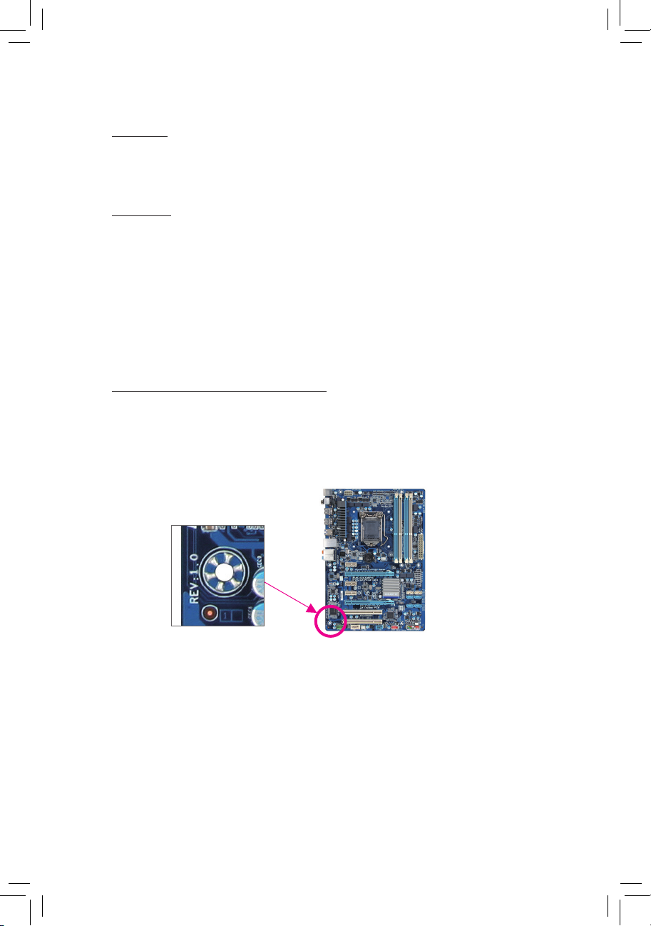
Identifying Your Motherboard Revision
The revision number on your motherboard looks like this: "REV: X.X." For example, "REV: 1.0"
means the revision of the motherboard is 1.0. Check your motherboard revision before updating
motherboard BIOS, drivers, or when looking for technical information.
Example:

- 4 -
Table of Contents
GA-H61MA-D3V Motherboard Layout ............................................................................5
GA-H61MA-D3V Motherboard Block Diagram ...............................................................6
Chapter 1 Hardware Installation .....................................................................................7
1-1 Installation Precautions ................................................................................... 7
1-2 Product Specications ..................................................................................... 8
1-3 Installing the CPU .......................................................................................... 10
1-4 Installing the Memory .....................................................................................11
1-5 Installing an Expansion Card ..........................................................................11
1-6 Back Panel Connectors ................................................................................. 12
1-7 Internal Connectors ....................................................................................... 13
Chapter 2 BIOS Setup ..................................................................................................20
2-1 Startup Screen ............................................................................................... 20
2-2 The Main Menu .............................................................................................. 21
2-3 M.I.T. ..............................................................................................................22
2-4 System ........................................................................................................... 29
2-5 BIOS Features ...............................................................................................30
2-6 Peripherals ..................................................................................................... 32
2-7 Power Management ....................................................................................... 34
2-8 Save & Exit .................................................................................................... 36
Chapter 3 Drivers Installation .......................................................................................37
Chapter 4 Appendix ......................................................................................................38
4-1 Conguring SATA Hard Drive(s) .................................................................... 38
4-2 Regulatory Statements .................................................................................. 40
- 5 -
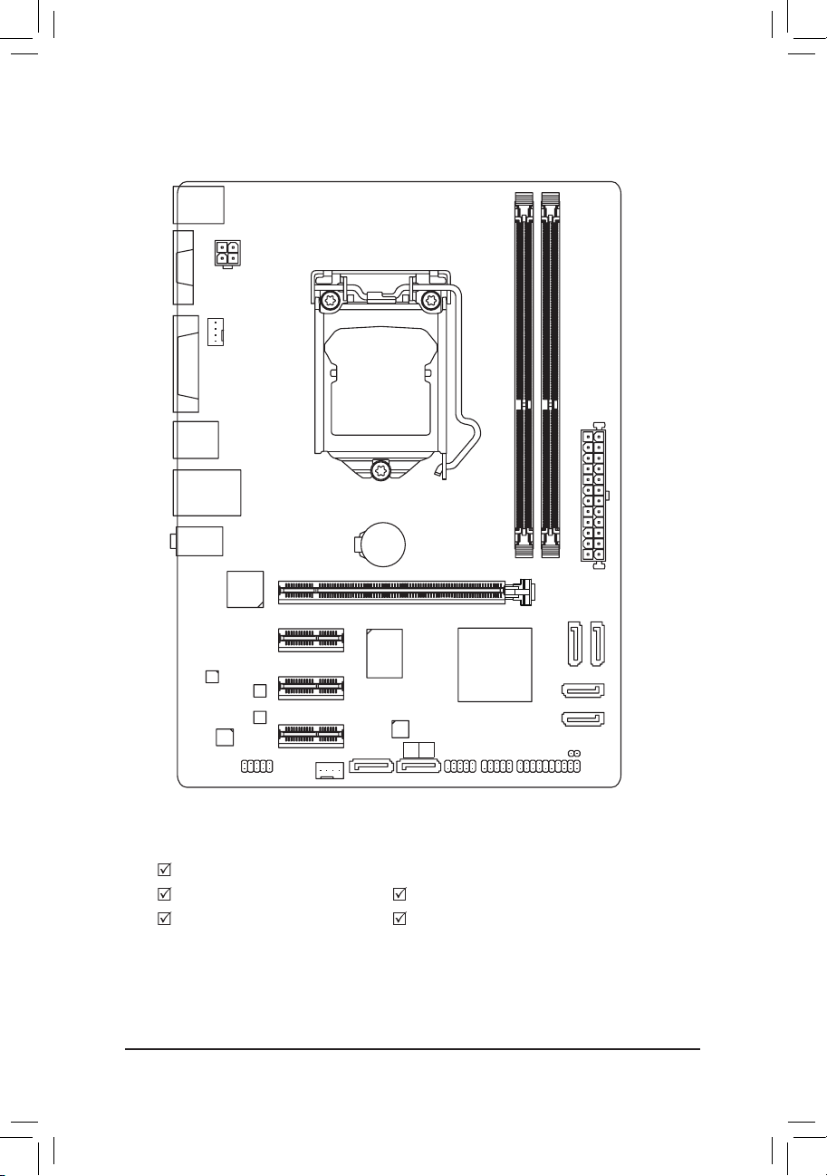
GA-H61MA-D3V Motherboard Layout
Box Contents
GA-H61MA-D3V motherboard
Motherboard driver disk Two SATA cables
User's Manual I/O Shield
* The box contents above are for reference only and the actual items shall depend on the product package you obtain.
KB_MS_USB
CPU_FAN
LGA1155
ATX
GA-H61MA-D3V
F_AUDIO
AUDIO
M_BIOS
DDR3_1
DDR3_2
BAT
F_PANEL
ATX_12V
Intel® H61
R_USB30
CODEC
CLR_CMOS
B_BIOS
VGA
USB_LAN
PCIEX16
PCIEX1_1
PCIEX1_2
F_USB1F_USB2
iTE
IT8728
SYS_FAN
DVI
Marvell
88SE9172
Etron
EJ168
GSATA3
1 0
PCIEX1_3
SATA2
SATA2
Realtek/
Atheros
GbE LAN
- 6 -
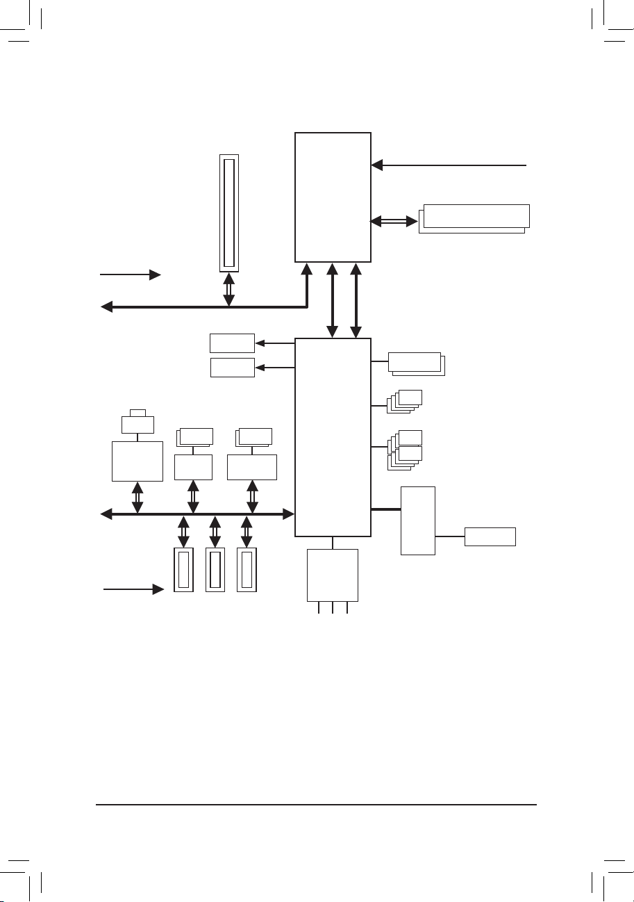
GA-H61MA-D3V Motherboard Block Diagram
PS/2 KB/Mouse
LGA1155
CPU
Intel® H61
PCIe CLK
(100 MHz)
PCI Express Bus
CPU CLK+/- (100 MHz)
1 PCI Express x16
Dual BIOS
8 USB 2.0/1.1
LPC
Bus
DDR3 1333/1066/800 MHz
LAN
RJ45
PCI Express Bus
PCIe CLK
(100 MHz)
iTE
IT8728
3 PCI Express x1
4 SATA 3Gb/s
D-Sub
DVI-D
x16
Dual Channel Memory
x1
x1
Line Out (Front Speaker Out)
MIC (Center/Subwoofer Speaker Out)
Line In (Rear Speaker Out)
CODEC
DMI 2.0
FDI
x1 x1
2 USB 3.0/2.0
Etron
EJ168
x1
2 SATA 6Gb/s
Marvell
88SE9172
x1
Realtek/
Atheros
GbE LAN

- 7 -
1-1 Installation Precautions
The motherboard contains numerous delicate electronic circuits and components which can
become damaged as a result of electrostatic discharge (ESD). Prior to installation, carefully read
the user's manual and follow these procedures:
Prior to installation, make sure the chassis is suitable for the motherboard. •
Prior to installation, do not remove or break motherboard S/N (Serial Number) sticker or •
warranty sticker provided by your dealer. These stickers are required for warranty validation.
Always remove the AC power by unplugging the power cord from the power outlet before •
installing or removing the motherboard or other hardware components.
When connecting hardware components to the internal connectors on the motherboard, •
make sure they are connected tightly and securely.
When handling the motherboard, avoid touching any metal leads or connectors. •
It is best to wear an electrostatic discharge (ESD) wrist strap when handling electronic com- •
ponents such as a motherboard, CPU or memory. If you do not have an ESD wrist strap,
keep your hands dry and rst touch a metal object to eliminate static electricity.
Prior to installing the motherboard, please have it on top of an antistatic pad or within an •
electrostatic shielding container.
Before unplugging the power supply cable from the motherboard, make sure the power sup- •
ply has been turned off.
Before turning on the power, make sure the power supply voltage has been set according to •
the local voltage standard.
Before using the product, please verify that all cables and power connectors of your hard- •
ware components are connected.
To prevent damage to the motherboard, do not allow screws to come in contact with the •
motherboard circuit or its components.
Make sure there are no leftover screws or metal components placed on the motherboard or •
within the computer casing.
Do not place the computer system on an uneven surface •
.
Do not place the computer system in a high-temperature environment. •
Turning on the computer power during the installation process can lead to damage to sys- •
tem components as well as physical harm to the user.
If you are uncertain about any installation steps or have a problem related to the use of the •
product, please consult a certied computer technician.
Chapter 1 Hardware Installation
- 8 -
1-2 ProductSpecications
CPU Support for Intel
®
Core™ i7 processors/Intel® Core™ i5 processors/
Intel® Core™ i3 processors/Intel® Pentium® processors/Intel® Celeron® processors
in the LGA1155 package
(Go to GIGABYTE's website for the latest CPU support list.)
L3 cache varies with CPU
Chipset Intel
®
H61 Express Chipset
Memory 2 x 1.5V DDR3 DIMM sockets supporting up to 16 GB of system memory
* Due to Windows 32-bit operating system limitation, when more than 4 GB of physical
memory is installed, the actual memory size displayed will be less than 4 GB.
Dual channel memory architecture
Support for DDR3 1333/1066/800 MHz memory modules
Support for non-ECC memory modules
(Go to GIGABYTE's website for the latest supported memory speeds and memory
modules.)
Onboard
Graphics
Integrated Graphics Processor:
- 1 x D-Sub port
- 1 x DVI-D port, supporting a maximum resolution of 1920x1200
* The DVI-D port does not support D-Sub connection by adapter.
Audio Realtek/VIA HD audio codec
High Denition Audio
2/4/5.1/7.1-channel
* To enable 7.1-channel audio, you have to use an HD front panel audio module and
enable the multi-channel audio feature through the audio driver.
LAN 1 x Realtek/Atheros GbE LAN chip (10/100/1000 Mbit)
Expansion Slots 1 x PCI Express x16 slot, running at x16
(The PCI Express x16 slot conforms to PCI Express 3.0 standard.)
* To support PCI Express 3.0, you must install an Intel 22nm CPU.
3 x PCI Express x1 slots
(The PCI Express x1 slots conform to PCI Express 2.0 standard.)
Storage Interface Chipset:
- 4 x SATA 3Gb/s connectors (SATA2 0/1/2/3) supporting up to 4 SATA 3Gb/s
devices
Marvell 88SE9172 chip:
- 2 x SATA 6Gb/s connectors (GSATA3 0/1) supporting up to 2 SATA 6Gb/s
devices
- Support for R AID 0 and R AID 1
USB Chipset:
- Up to 8 USB 2.0/1.1 ports (4 ports on the back panel, 4 ports available
through the internal USB headers)
Etron EJ168 chip:
- Up to 2 USB 3.0/2.0 ports on the back panel
- 9 -
Internal
Connectors
1 x 24-pin ATX main power connector
1 x 4-pin ATX 12V power connector
4 x SATA 3Gb/s connectors
2 x SATA 6Gb/s connectors
1 x CPU fan header
1 x system fan header
1 x front panel header
1 x front panel audio header
2 x USB 2.0/1.1 headers
1 x Clear CMOS jumper
Back Panel
Connectors
1 x PS/2 keyboard/mouse port
1 x D-Sub port
1 x DVI-D port
4 x USB 2.0/1.1 ports
2 x USB 3.0/2.0 ports
1 x RJ-45 port
3 x audio jacks (Line In/Line Out/Microphone)
I/O Controller iTE IT8728 chip
Hardware
Monitor
System voltage detection
CPU/System temperature detection
CPU/System fan speed detection
CPU overheating warning
CPU/System fan fail warning
CPU/System fan speed control
* Whether the CPU/system fan speed control function is supported will depend on
the CPU/system cooler you install.
BIOS 2 x 32 Mbit ash
Use of licensed AMI EFI BIOS
Support for DualBIOS
™
PnP 1.0a, DMI 2.0, SM BIOS 2.6, ACPI 2.0a
Bundled
Software
Norton Internet Security (OEM version)
Unique Features Support for @BIOS
Support for Q-Flash
Support for Xpress Recovery2
Support for EasyTune
* Available functions in EasyTune may differ by motherboard model.
Support for ON/OFF Charge
Operating
System
Support for Microsoft
®
Windows 7/Vista/XP
Form Factor Micro ATX Form Factor; 24.4cm x 17.4cm
* GIGABYTE reser ves the right to make any c hanges to the product specications and product-related information
without prior notice.
- 10 -
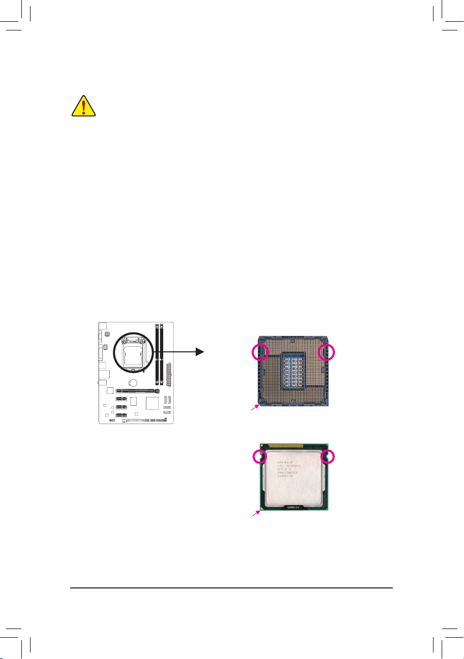
1-3 Installing the CPU
Installing the CPU
A. Locate the alignment keys on the motherboard CPU socket and the notches on the CPU.
Alignment KeyAlignment Key
LGA1155 CPU Socket
Pin One Corner of the CPU Socket
Notch
Notch
LGA1155 CPU
Triangle Pin One Marking on the CPU
Read the following guidelines before you begin to install the CPU:
Make sure that the motherboard supports the CPU. •
(Go to GIGABYTE's website for the latest CPU support list.)
Always turn off the computer and unplug the power cord from the power outlet before installing •
the CPU to prevent hardware damage.
Locate the pin one of the CPU. The CPU cannot be inserted if oriented incorrectly. (Or you may •
locate the notches on both sides of the CPU and alignment keys on the CPU socket.)
Apply an even and thin layer of thermal grease on the surface of the CPU. •
Do not turn on the computer if the CPU cooler is not installed, otherwise overheating and dam- •
age of the CPU may occur.
Set the CPU host frequency in accordance with the CPU specications. It is not recommended •
that the system bus frequency be set beyond hardware specications since it does not meet the
standard requirements for the peripherals. If you wish to set the frequency beyond the standard
specications, please do so according to your hardware specications including the CPU, graphics card, memory, hard drive, etc.
- 11 -
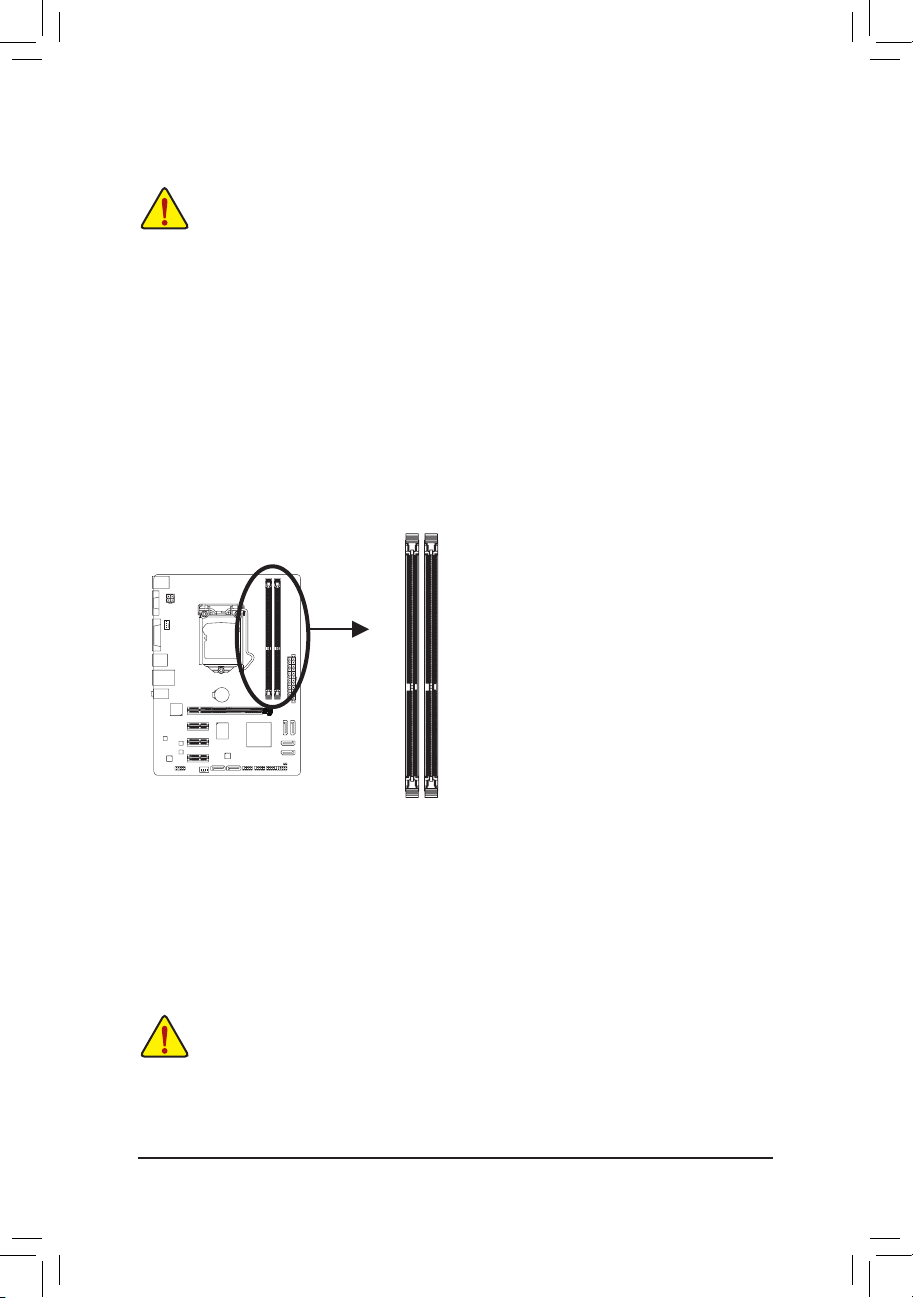
1-4 Installing the Memory
Due to CPU limitations, read the following guidelines before installing the memory in Dual Channel mode.
Dual Channel mode cannot be enabled if only one DDR3 memory module is installed.1.
When enabling Dual Channel mode with two memory modules, it is recommended that memory of 2.
the same capacity, brand, speed, and chips be used for optimum performance.
DualChannelMemoryConguration
This motherboard provides two DDR3 memory sockets and supports Dual Channel Technology. After the
memory is installed, the BIOS will automatically detect the specifications and capacity of the memory.
Enabling Dual Channel memory mode will double the original memory bandwidth.
The two DDR3 memory sockets are divided into two channels and each channel has one memory socket as
following:
Channel A: DDR3_1
Channel B: DDR3_2
Read the following guidelines before you begin to install the memory:
Make sure that the motherboard supports the memory. It is recommended that memory of the •
same capacity, brand, speed, and chips be used.
(Go to GIGABYTE's website for the latest supported memory speeds and memory modules.)
Always turn off the computer and unplug the power cord from the power outlet before installing •
the memory to prevent hardware damage.
Memory modules have a foolproof design. A memory module can be installed in only one direc- •
tion. If you are unable to insert the memory, switch the direction.
1-5 Installing an Expansion Card
Read the following guidelines before you begin to install an expansion card:
Make sure the motherboard supports the expansion card. Carefully read the manual that came •
with your expansion card.
Always turn off the computer and unplug the power cord from the power outlet before installing •
an expansion card to prevent hardware damage.
DDR3_1
DDR3_2
- 12 -
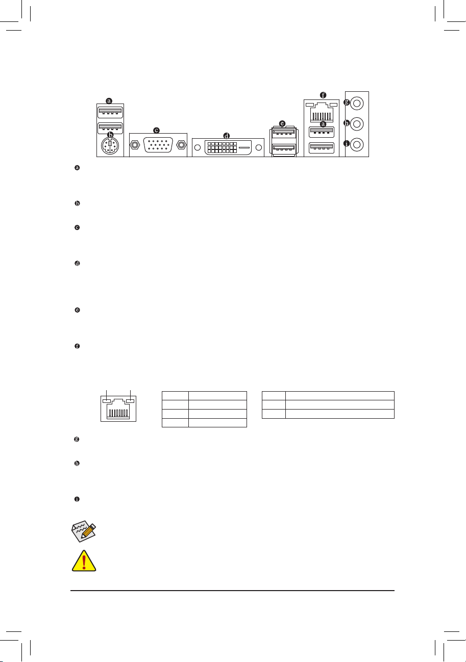
1-6 Back Panel Connectors
USB 2.0/1.1 Port
The USB port supports the USB 2.0/1.1 specication. Use this port for USB devices such as a USB keyboard/mouse, USB printer, USB ash drive and etc.
PS/2 Keyboard/Mouse Port
Use this port to connect a PS/2 mouse or keyboard.
D-Sub Port
The D-Sub port supports a 15-pin D-Sub connector. Connect a monitor that supports D-Sub connection
to this port.
DVI-D Port
The DVI-D port conforms to the DVI-D specication and supports a maximum resolution of 1920x1200
(the actual resolutions supported depend on the monitor being used). Connect a monitor that supports
DVI-D connection to this port. (Note: The DVI-D port does not support D-Sub connection by adapter.)
USB 3.0/2.0 Port
The USB 3.0 port supports the USB 3.0 specication and is compatible to the USB 2.0/1.1 specication.
Use this port for USB devices such as a USB keyboard/mouse, USB printer, USB ash drive and etc.
RJ-45 LAN Port
The Gigabit Ethernet LAN port provides Internet connection at up to 1 Gbps data rate. The following
describes the states of the LAN port LEDs.
Line In Jack (Blue)
The default line in jack. Use this audio jack for line in devices such as an optical drive, walkman, etc.
Line Out Jack (Green)
The default line out jack. Use this audio jack for a headphone or 2-channel speaker. This jack can be
used to connect front speakers in a 4/5.1/7.1-channel audio conguration.
Mic In Jack (Pink)
The default Mic in jack. Microphones must be connected to this jack.
Activity LED
Connection/
Speed LED
LAN Port
Activity LED:Connection/Speed LED:
State Description
Orange 1 Gbps dat a rate
Green 100 Mb ps data rate
Off 10 Mbps dat a rate
State Description
Blinking Da ta transmissi on or receivin g is occurrin g
Off No data t ransmission o r receiving is oc curring
When removing the cable connected to a back panel connector, rst remove the cable from your •
device and then remove it from the motherboard.
When removing the cable, pull it straight out from the connector. Do not rock it side to side to •
prevent an electrical short inside the cable connector.
To congure 7.1-channel audio, you have to use an HD front panel audio module and enable the
multi-channel audio feature through the audio driver.
- 13 -
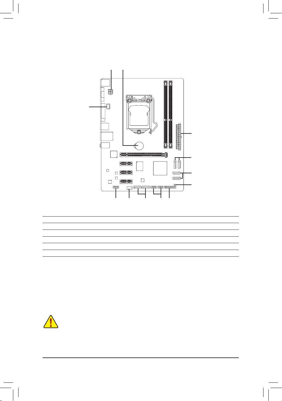
1-7 Internal Connectors
Read the following guidelines before connecting external devices:
First make sure your devices are compliant with the connectors you wish to connect. •
Before installing the devices, be sure to turn off the devices and your computer. Unplug the •
power cord from the power outlet to prevent damage to the devices.
After installing the device and before turning on the computer, make sure the device cable has •
been securely attached to the connector on the motherboard.
1) ATX_12V
2) ATX
3) CPU_FAN
4) SYS_FAN
5) SATA2 0/1/2/3
6) GSATA3 1/0
7) F_PANEL
8) F_AUDIO
9) F_USB1/2
10) CLR_CMOS
11) BAT
1211
8 4
3
5
76 9
5
10

- 14 -
131
2412
ATX
ATX:
1/2) ATX_12V/ATX (2x2 12V Power Connector and 2x12 Main Power Connector)
With the use of the power connector, the power supply can supply enough stable power to all the
components on the motherboard. Before connecting the power connector, rst make sure the power
supply is turned off and all devices are properly installed. The power connector possesses a foolproof
design. Connect the power supply cable to the power connector in the correct orientation. The 12V
power connector mainly supplies power to the CPU. If the 12V power connector is not connected, the
computer will not start.
To meet expansion requirements, it is recommended that a power supply that can withstand high
power consumption be used (500W or greater). If a power supply is used that does not provide
the required power, the result can lead to an unstable or unbootable system.
ATX_12V:
Pin No. Denition
1 GND
2 GND
3 +12V
4 +12V
ATX_12V
2
1
4
3
Pin No. Denition Pin No. Denition
1 3.3V 13 3.3V
2 3.3V 14 -12V
3 GND 15 GND
4 +5V 16 PS_ON (soft On/Off)
5 GND 17 GND
6 +5V 18 GND
7 GND 19 GND
8 Power Good 20 -5V
9 5VSB (stand by +5V) 21 +5V
10 +12V 22 +5V
11 +12V (Only for 2x12-pin ATX) 23 +5V (Only for 2x12-pin ATX)
12 3.3V (Only for 2x12-pin ATX) 24 GND (Only for 2x12-pin ATX)
 Loading...