How it Works
Log In / Sign Up
Buy Points
How it Works
FAQ
Contact Us
Questions and Suggestions
Users
Gigabyte
Loading...
G
GA-B75M-D3V
12
GA-B75M-D3V-JP
GA-B75M-D3V-R1.0
GA-B75M-HD3
8
GA-B75M-HD3-10T
GA-B75M-HD3-10T BV
GA-B75N
6
GA-B75TN
12
GA-B75TN-CC
GA-B75TN-GB
GA-B75TN-SI
GA-B85-D3V
4
GA-B85-D3V-A
GA-B85-D3V-A-SI
GA-B85-D3V-S1
GA-B85-D3V-SI
GA-B85-HD3
10
GA-B85-HD3-A
4
GA-B85-HD3-SI
GA-B85M-D2V
4
GA-B85M-D2V PLUS
2
GA-B85M-D2V-SI
GA-B85M-D2V-TM
GA-B85M-D3H
7
GA-B85M-D3H-A
GA-B85M-D3V
10
GA-B85M-D3V-A
5
GA-B85M-D3V-A-SI
GA-B85M-D3V-A-SI-1.0
GA-B85M-D3V PLUS
3
GA-B85M-DASH
4
GA-B85M-DS3H
7
GA-B85M-DS3H-A
6
GA-B85M-GAMING 3
3
GA-B85M-HD3
8
GA-B85M-HD3-A
3
GA-B85M-HD3 R4
GA-B85M-PIO-SI
GA-B85N
4
GA-B85N PHOENIX
5
GA-B85N Phoenix-WIFI
4
GA-B85N-WIFI
3
GA-B85TN
3
GA-B85TN (rev. 1.0)
GA-BX2000
5
GA-BX2000 1.1
GA-C1007UN
3
GA-C1007UN-D
6
GA-C1037UN
5
GA-C1037UN-EU
4
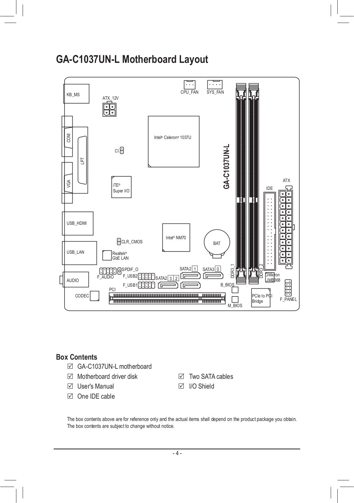
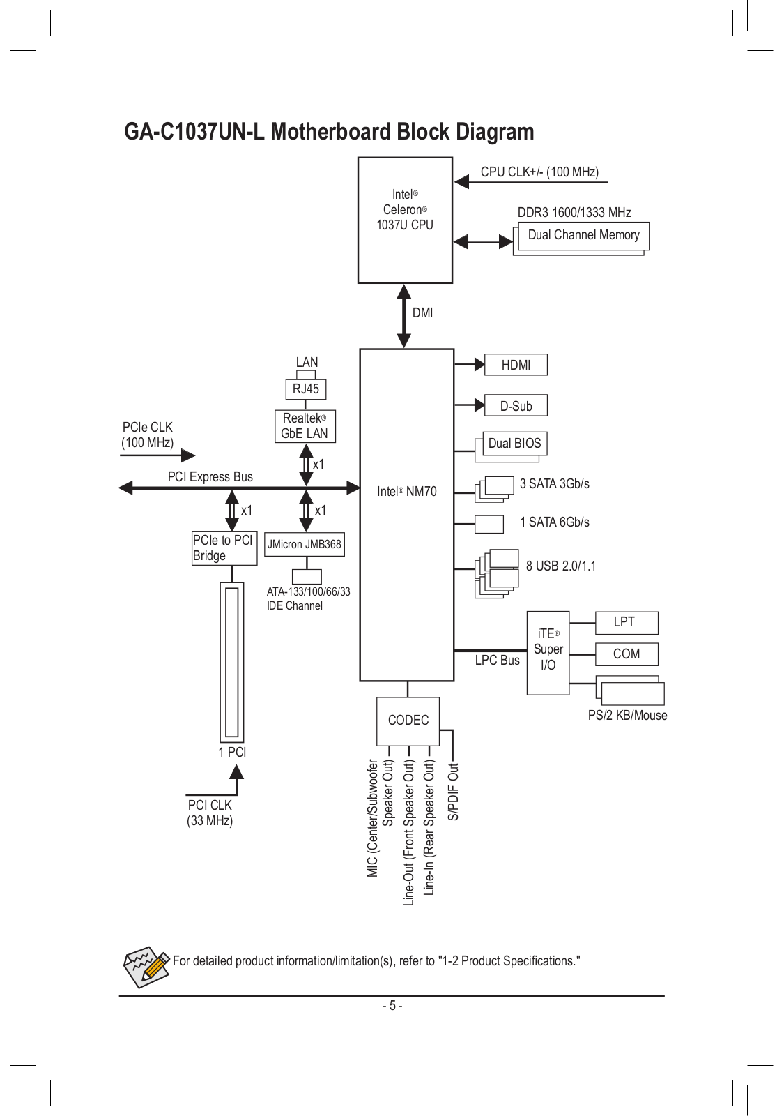
GA-C1037UN-L
3
GA-C1037UN-LA
2
GA-C261-WD12
GA-C261-WD12-IPMI
GA-C7V7-RH
GA-C807N
2
GA-C807N User's manual
GA-C847N
5
GA-C847N-D
5
GA-C847N-S2-DB
GA-D1USA22
GA-D425TU
GA-D425TUD
13
GA-D510UD
13
GA-D510UD (rev. 1.0)
GA-D525E-C6
GA-D525TUD
17
GA-E2100N
4
GA-E240N
3
GA-E350N
5
GA-E350N-USB3
14
GA-E350N WIN8
5
GA-E6010N
GA-E7AUM-DS2H
4
GA-EG31MF-S2
4
GA-EG31M-S2
6
GA-EG41MF-S2H
4
GA-EG41MFT-US2H
19
GA-EG41MF-US2H
7
GA-EG41M-S2
GA-EG41M-S2H
5
GA-EG41M-US2H
5
GA-EG43M-S2H
5
GA-EG45M-DS2H
7
GA-EG45M-DS2H Rev 1.02
GA-EG45M-UD2H
4
GA-EP31-DS3L
11
GA-EP35C-DS3R
4
GA-EP35-DS3
18
GA-EP35-DS3L
12
GA-EP35-DS3P
17
GA-EP35-DS3R
20
GA-EP35-DS3 (rev. 2.1)
GA-EP35-DS3R (rev. 2.1)
GA-EP35-DS4
18
GA-EP35-S3L
GA-EP41T-UD3L
14
GA-EP41T-USB3
12
GA-EP41-UD3L
14
GA-EP41-US3L
6
Loading...
Loading...
Nothing found
GA-C1037UN-L
Schematic rev.1.0
31 pgs
658.53 Kb
0
User Manual
32 pgs
10.85 Mb
0
User Manual [zh]
32 pgs
11.56 Mb
0
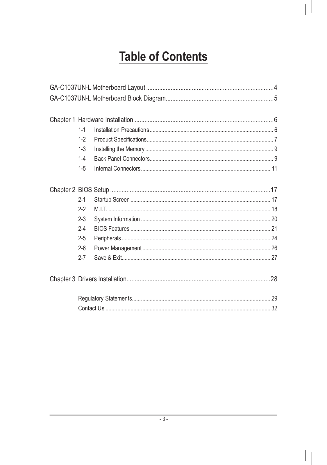
Table of contents
Loading...
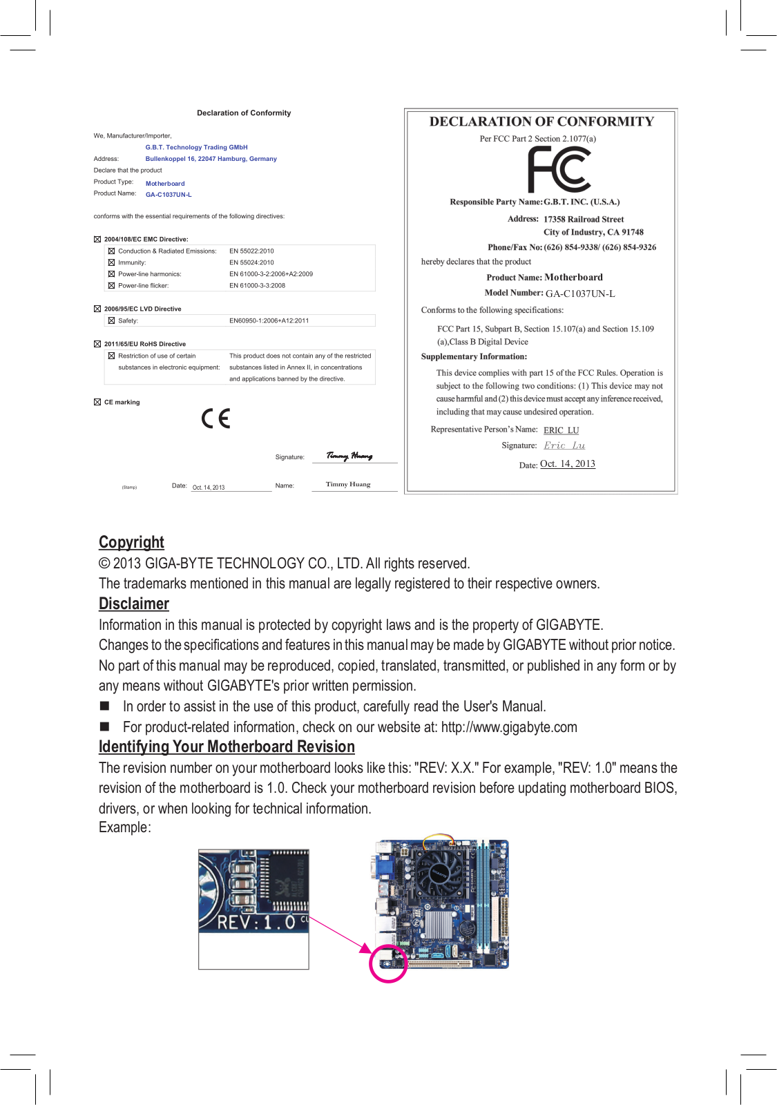
Gigabyte GA-C1037UN-L User Manual
...
Gigabyte User Manual
Download
Specifications and Main Features
Frequently Asked Questions
User Manual
Download
Loading...
+
hidden pages
Unhide
You need points to download manuals.
1 point = 1 manual.
You can buy points or you can get point for every manual you upload.
Buy points
Upload your manuals
 Loading...