

Page 1
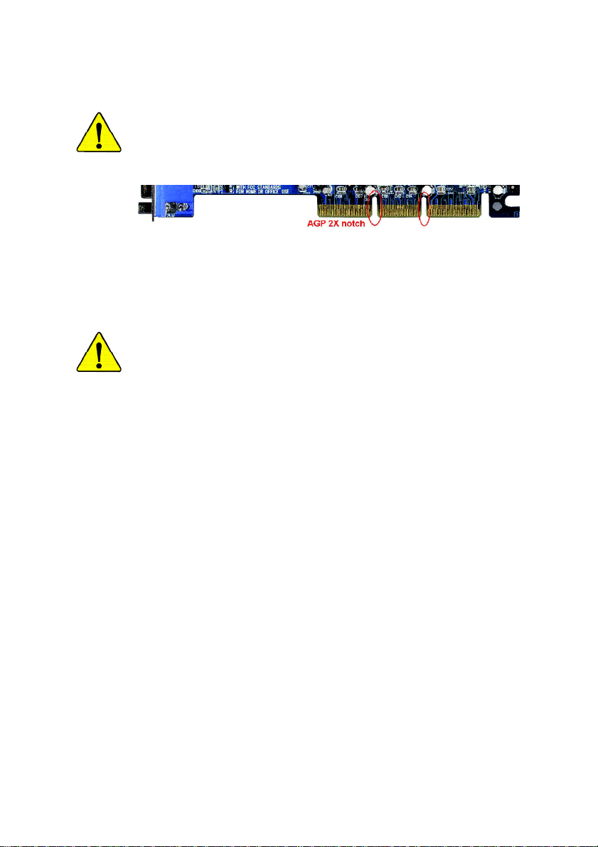
When you installing AGP card, please make sure the following notice
is fully understood and practiced. If your AGP card has "AGP 4X
(1.5V) notch"(show below), please make sure your AGP card is AGP
4X (1.5V).
AGP 4X notch
Caution: AGP 2X card is not supported by GA-8VM533. You might
experience system unable to boot up normally. Please insert an AGP 4X
card.
Example 1: Diamond Vipper V770 golden finger is compatible with 2X/4X
mode AGP slot. It can be switched between AGP 2X(3.3V) or 4X(1.5V) mode
by adjusting the jumper. The factory default for this card is 2X(3.3V).
The GA-8VM533 (or any AGP 4X only) motherboards might not function
properly, if you install this card without switching the jumper to
4X(1.5V) mode in it.
Example 2: Some ATi Rage 128 Pro graphics cards made by "Power Color",
the graphics card manufacturer & some SiS 305 cards, their golden finger is
compatible with 2X(3.3V)/4X(1.5V) mode AGP slot, but they support 2X(3.3V)
only. The GA-8VM533 (or any AGP 4X only) motherboards might not function
properly, If you install this card in it.
Note : Although Gigabyte's AG32S(G) graphics card is based on ATi Rage
128 Pro chip, the design of AG32S(G) is compliance with AGP 4X(1.5V)
specification. Therefore, AG32S(G) will work fine with GA-8VM533 based
motherboards.
Page 2
The author assumes no responsibility for any errors or
omissions that may appear in this document nor does the
author make a commitment to update the information
contained herein.
Third-party brands and names are the property of their
respective owners.
Please do not remove any labels on motherboard, this may
void the warranty of this motherboard.
Due to rapid change in technology, some of the
specifications might be out of date before publication of
this booklet.
Page 3

Ausschla ger Weg 41, 1F, 20537 Hamburg, Germany
( description of the apparatus, system, installation to which it refers)
(reference to the specification under which con formity is declared)
in accordance with 89/336 EEC-EMC Directive
o EN 55011 Limits and methods of measurement
o EN 55013
o EN 55014 Limits and methods of measurement
o EN 55015 Limits and methods of measurement
o EN 55020
T EN 55022 Limits and methods of measurement
o DIN VDE 0855
o part 10
o part 12
T CE marking
o EN 60065
o EN 60335
of radio disturbance characteristics of
industrial,scientific and medical (ISM
high frequency equipment
Limits and methods of measurement
of radio disturbance characteristics of
broadcast receivers and associated
equipment
of radio disturbance characteristics of
household electrical appliances,
portable tools and similar electrical
apparatus
of radio disturbance characteristics of
fluorescent lamps and luminaries
Immunity from radio interference of
broadcast receivers and associated
equipment
of radio disturbance characteristics of
information technology equipment
Cabled distribution systems; Equipment
for receiving and/or distribution from
sound and television signals
The manufacturer also declares the conformity of above mentioned product
Safety requirements for mains operated
electronic and related apparatus for
household and similar general use
Safety of household and similar
electrical appliances
(Stamp)
with the actual required safety standards in accordance with LVD 73/23 EEC
Declaration of Conformity
We, Manufacturer/Importer
(full address)
G.B.T. Tec hnology Träding GMbH
declare that the product
Mother Board
GA-8VM533
is in conformity with
o EN 61000-3-2*
T EN 60555-2
o EN 61000-3-3* Disturbances in supply systems cause
T EN 60555-3
T EN 50081-1
T EN 50082-1
o EN 55081-2
o EN 55082-2
o ENV 55104
o EN50091-2
(EC conformity marking)
o EN 60950
o EN 50091-1
Manufacturer/Importer
Date : October 2, 2003
Disturbances in supply systems cause
by household appliances and similar
electrical equipment “Harmonics”
by household appliances and similar
electrical equipment “Voltage fluctuations”
Generic emission standard Part 1:
Residual commercial and light industry
Generic immunity standard Part 1:
Residual commercial and light industry
Generic emission standard Part 2:
Industrial environment
Generic emission standard Part 2:
Industrial environment
lmmunity requirements for household
appliances tools and similar apparatus
EMC requirements for uninterruptible
power systems (UPS)
Safety for information technology equipment
including electrical bussiness equipment
General and Safety requirements for
uninterruptible power systems (UPS)
Signature:
Name:
Timmy Huang
Timmy Huang
Page 4

DECLARATION OF CONFORMITY
Per FCC Part 2 Section 2.1077(a)
Responsible Party Name:
Add ress:
Phone/Fax No:
hereby declares that the product
Product Name: Motherboard
Model Nu mber: GA-8VM533
Conforms to the follow ing specifications:
FCC Part 15, Subpart B, S ection 15.107(a) and Section 15.109(a),
Class B Digital Device
Supplementary Information:
This device complies with part 15 of the FCC Rules. Operation is
subject to t he following two conditions: (1) This device may not
cause harmful and (2) this device must accept any inference received,
including that may cause undes ired operation.
Representative Person’s Name:
Signature:
G.B.T. INC. (U.S.A .)
17358 Railroad Street
City of Indu stry, CA 91748
(818) 854-9338/ (818) 854-9339
ERIC LU
Eric Lu
Date:
October 2, 2003
Page 5

GA-8VM533
P4 Titan Series Motherboard
USER'S MANUAL
Pentium® 4 Processor Motherboard
Rev. 1002
12ME-8VM533-1002
Page 6

English
Item Checklist ..................................................................................... 4
WARNING! .......................................................................................... 4
Chapter 1 Introduction ........................................................................ 5
Chapter 2 Hardware Installation Process ........................................... 11
Table of Content
Features Summary ......................................................................................... 5
GA-8VM 533 Motherboard Layout .................................................................. 7
Block Diagram ................................................................................................ 8
Step 1: Install the Central Processing Unit (CPU) ...................................... 12
Step 1-1: CPU Installation ......................................................................................... 12
Step 1-2: CPU Cooling Fan Installation .....................................................................13
Step 2: Install Memory Modules .................................................................. 14
Step 3: Install expansion cards .................................................................... 16
Step 4: Connect ribbon cables, cabinet wires and power supply............. 17
Step 4-1: I/O Back Panel Introduction ....................................................................... 17
Step 4-2: Connectors Introduction .............................................................................19
Chapter 3 BIOS Setup ....................................................................... 27
The Main Menu (For example: BIOS Ver. : F1) ......................................... 2 8
Standard CMOS Features ........................................................................... 30
Advanced BIOS Features ............................................................................. 33
Integrated Peripherals ................................................................................. 35
Power Management Setup .......................................................................... 38
- 2 -GA-8VM533 Motherboard
Page 7

PnP/PCI Configurations ................................................................................ 41
PC Health Status ........................................................................................... 42
Frequency/Voltage Control ........................................................................... 43
Load Fail-Safe Defaults ................................................................................ 45
Load Optimized Defaults .............................................................................. 46
Set Supervisor/User Password..................................................................... 4 7
Save & Exit Setup .......................................................................................... 4 8
Exit Without Saving ....................................................................................... 49
Chapter 4 Technical Reference ......................................................... 51
@BIOS™ Introduction .................................................................................. 51
EasyTune™ 4 Introduction .......................................................................... 52
Flash BIOS Method Introduction ................................................................. 5 3
Method 1 : Q- Flash ................................................................................................... 53
Method 2 : @BIOS Utility .......................................................................................... 66
6-Channel Audio Function Introduction ...................................................... 6 8
Xpress Recovery Introduction ...................................................................... 71
English
Chapter 5 Appendix .......................................................................... 75
- 3 -
Table of Content
Page 8
Item Checklist
English
Computer motherboards and expansion cards contain very delicate Integrated Circuit (IC) chips. To
protect them against damage from static electricity, you should follow some precautions whenever you
work on your computer.
The GA-8VM533 motherboard 2 Por t USB Cabl e x 1
IDE cabl e x 1 / Floppy cable x 1 4 Por t USB Cabl e x 1
CD for motherboard driver & utility SPDIF-KIT x 1 (SPDIF Out KIT)
GA-8VM533 user's m anual IEEE 1394 Cable x1
I/O Shield Audio C ombo Kit x 1
Quick PC Install ation Guide (SUR ROUND-Ki t + SPDIF O ut KIT)
RAID Manual Motherboard Settings Label
GC-SATA Card (Optional) SATA RAID Manual
(M anual; SATA cable x1; P ower cabl e x 1) SATA cable x 1
WARNING!
1. Unplug your computer when working on the inside.
2. Use a grounded wrist strap before handling computer components. If you do not have
one, touch both of your hands to a safely grounded object or to a metal object, such as
the power supply case.
3. Hold components by the edges and try not touch the IC chips, leads or connectors, or
other components.
4. Place components on a grounded antistatic pad or on the bag that came with the
components whenever the components are separated from the system.
5. Ensure that the ATX power supply is switched off before you plug in or remove the ATX
power connector on the motherboard.
Installing the motherboard to the chassis…
If the motherboard has mounting holes, but they don’t line up with the holes on the base and there are
no slots to attach the spacers, do not become alarmed you can still attach the spacers to the mounting
holes. Just cut the bottom portion of the spacers (the spacer may be a little hard to cut off, so be careful
of your hands). In this way you can still attach the motherboard to the base without worrying about short
circuits. Sometimes you may need to use the plastic springs to isolate the screw from the motherboard
PCB surface, because the circuit wire may be near by the hole. Be careful, don’t let the screw contact
any printed circuit write or parts on the PCB that are near the fixing hole, otherwise it may damage the
board or cause board malfunctioning.
- 4 -GA-8VM533 Motherboard
Page 9

Chapter 1 Introduction
Features Summary
Form Factor — 24.5cm x 20.8cm Micro ATX size form factor, 4 layers PCB
CP U — Socket 478 for Intel® Micro FC-PGA2 Pentium® 4 processor
— Support Intel® Pentium® 4 (Northwood) processor
— Support Intel® Pentium® 4 Processor with HT Technology *
— Intel® Pentium® 4 533/400MHz FSB
— 2nd cache depends on CPU
Chipset — VIA P4M533 Memory/AGP/PCI Controller (PAC)
— VIA VT8235 Integrated Peripheral Controller (PSIPC)
Memory — 2 184-pin DDR sockets
— Supports DDR266/DDR200 DIMM
— Supports up to 2GB DDR (Max)
— Supports only 2.5V DDR DIMM
I/O Control — ITE8705
Slots — 1 AGP slot supports 4X mode(1.5V)
— 3 PCI slot supports 33MHz & PCI 2.2 compliant
On-Board IDE — 2 IDE bus master (UDMA33/ATA66/ATA100/ATA133) IDE ports
for up to 4 ATAPI devices
— Supports PIO mode3,4 (UDMA 33/ATA66/ATA100/ATA133) IDE
& ATAPI CD-ROM
On-Board Peripherals — 1 Floppy port supports 2 FDD with 360K, 720K,1.2M, 1.44M
and 2.88M bytes
— 1 Parallel port supports Normal/EPP/ECP mode
— 1 Serial port (COMA), 1 VGA port
— 6 USB 2.0/1.1 ports (2 x Rear, 4 x Front by cable)
— 1 Front Audio connector
English
- 5 -
to be continued......
Introduction
Page 10

Hardware Monitor — CPU fan revolution detect
English
On-Board LAN — Builit in VIA 6103 Chipset
On-Board Sound — VIA VT1616 CODEC
PS/2 Connector — PS/2 Keyboard interface and PS/2 Mouse interface
BIOS — Licensed Award BIOS
Additional Features — PS/2 Keyboard power on by password
— CPU temperature detect
— System voltage detect
— CPU fan fail warning
— 1 RJ45 port
— Line Out / 2 front speaker
— Line In / 2 rear speaker(by s/w switch)
— Mic In / center& subwoofer(by s/w switch)
— CD_In
— Supports Q-Flash
— PS/2 Mouse power on
— STR (Suspend-To-RAM)
— AC Recovery
— Poly fuse for keyboard over-current protection
— USB KB/Mouse wake up from S3
— Supports @BIOS
— Supports EasyTune 4
"*" HT functionality requirement content :
Enabling the functionality of Hyper-Threading Technology for your computer system requires all
of the following platform components:
- CPU: An Intel® Pentium 4 Processor with HT Technology
- Chipset: An VIA Chipset that supports HT Technology
- BIOS: A BIOS that supports HT Technology and has it enabled
- OS: An operation system that has optimizations for HT Technology
Please set the CPU host frequency in accordance with your processor's specifications.
We don't recommend you to set the system bus frequency over the CPU's specification because
these specific bus frequencies are not the standard specifications for CPU, chipset and most of the
peripherals. Whether your system can run under these specific bus frequencies properly will
depend on your hardware configurations, including CPU, Chipsets, Memory, Cards… etc.
- 6 -GA-8VM533 Motherboard
Page 11
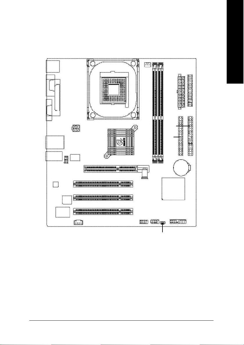
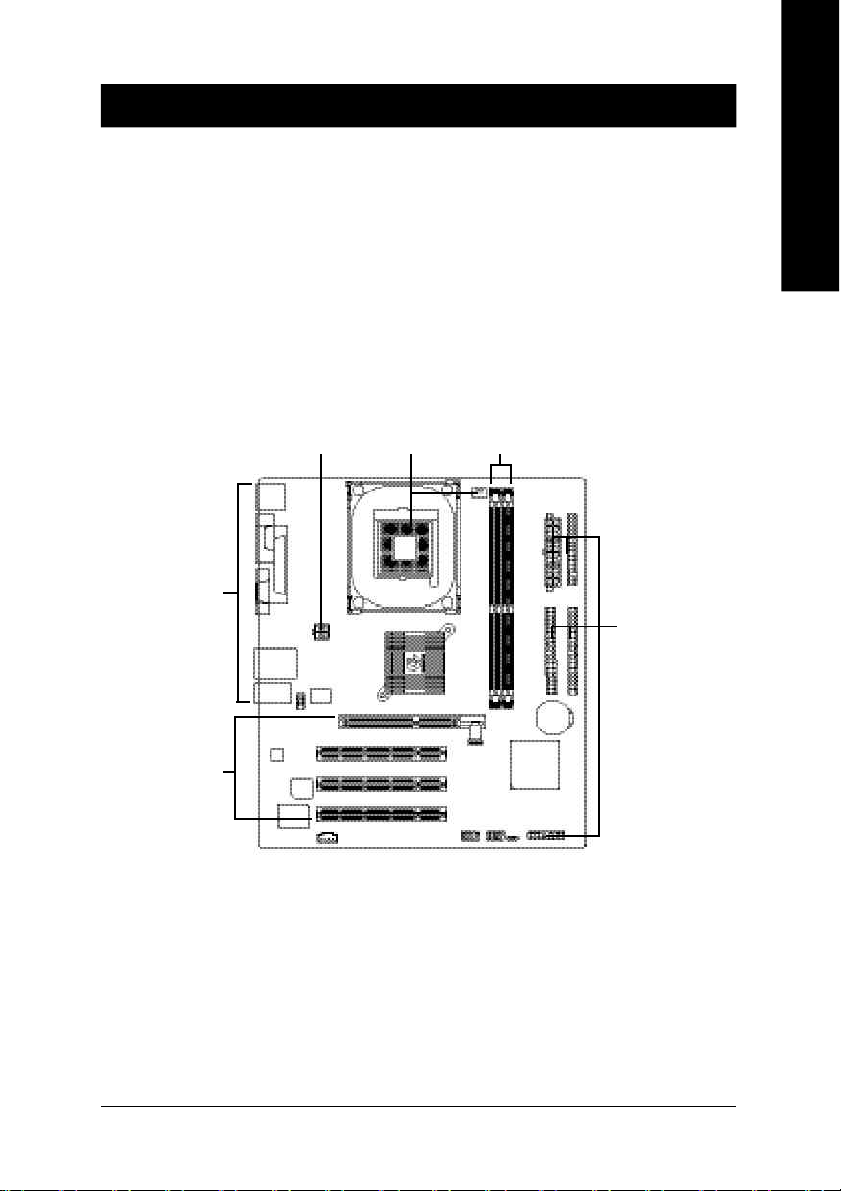
GA-8VM533 Motherboard Layout
English
KB_MS
VGA
USB
AUDIO
CODEC
COMA
F_AU DIO
ITE 870 5
LPT
LAN
BIOS
CD _IN
ATX_12 V
VT6 1 03
SOC KET 478
VIA P4M 533
PCI1
PCI2
PCI3
F_U SB1
CPU_FAN
IDE1
IDE2
GA-8VM533
DDR2
DDR1
VIA 8235
F_U SB2
FD D
ATX
BAT
F_PANEL
- 7 -
PWR_ LED
Introduction
Page 12
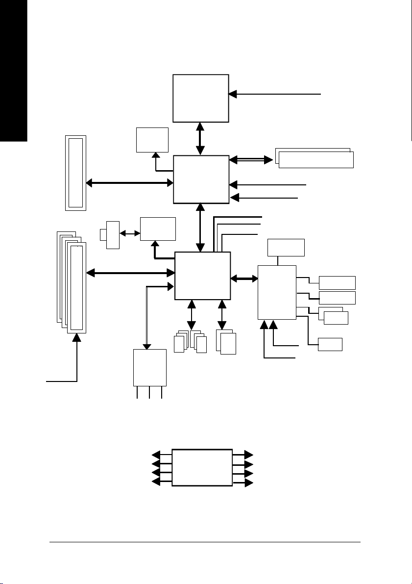
Block Diagram
English
PCICL K
(33MHz)
AGP 4X
3 P CI
AGPC LK
66MHz
RJ45
PCI BUS 33MHz
VGA Port
VT6103
MII
AC97 Link
6 Chann el
CODE C
MIC
LINE-IN
Pentium 4
Socket 478
6 U SB
Ports
LINE-OUT
CP U
System Bus
533/400MHz
VIA
P4M533
66MHz V_Link
VIA
VT8235
ATA33/66/
100/133
IDE Channels
CPUCLK+/- ( 100/133MHz)
200/266MHz
MCHCLK (100/133M Hz)
AGPCLK66 MHz
33 MHz
48 MHz
LPC BUS
14.318 MHz
BIOS
IT8705
24 MHz
33 MHz
DDR
Flop py
LPT Port
PS/2 KB /Mouse
1 COM Port
PCICLK (33M Hz)
USBCLK (48 MHz)
14.318 MHz
33 MHz
CLK
GEN
- 8 -GA-8VM533 Motherboard
MCHCLK (100/133M Hz)
CPUCLK+/- ( 100/133MHz)
AGPCLK (66M Hz)
V_Link (66MHz)
Page 13

English
- 9 -
Introduction
Page 14

English
- 10 -GA-8VM533 Motherboard
Page 15
Chapter 2 Hardware Installation Process
To set up your computer, you must complete the following steps:
Step 1- Install the Central Processing Unit (CPU)
Step 2- Install memory modules
Step 3- Install expansion cards
Step 4- Connect ribbon cables, cabinet wires, and power supply
English
Step 4
Step 4
Step 3
Congratulations! You have accomplished the hardware installation!
Turn on the power supply or connect the power cable to the power outlet. Continue with the
BIOS/software installation.
Step 1
Step 2
Step 4
- 11 - Hardware Installation Proc ess
Page 16
Step 1: Install the Central Processing Unit (CPU)
English
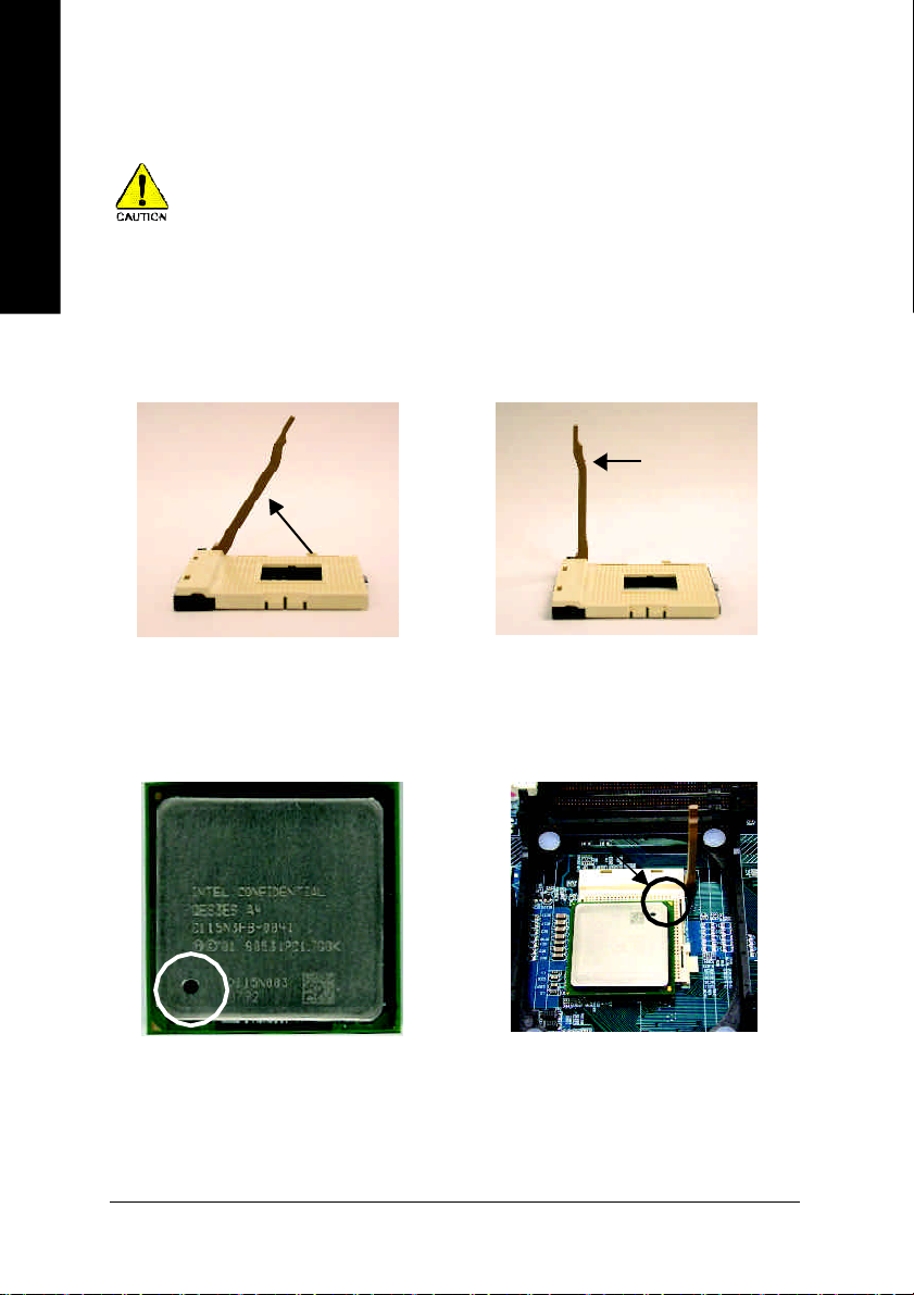
Step 1-1: CPU Installation
Before installing the processor, adhere to the following warning:
1. Please make sure the CPU type is supported by the motherboard.
2. If you do not match the CPU socket Pin 1 and CPU cut edge well, it will
cause improper installation. Please change the insert orientation.
Angling the
rod to 65
1. Angling the rod to 65-degree maybe
feel a kind of tight , and then continue
pull the rod to 90-degree when a noise
"cough" made.
0
Pin1 indicator
3. CPU Top View
Socket
Actuation
Lever
2. Pull the rod to the 90-degree directly.
Pin1 indicator
4. Locate Pin 1 in the socket and
look for a (golden) cut edge on the
CPU upper corner. Then insert
the CPU into the socket.
- 12 -GA-8VM533 Motherboard
Page 17
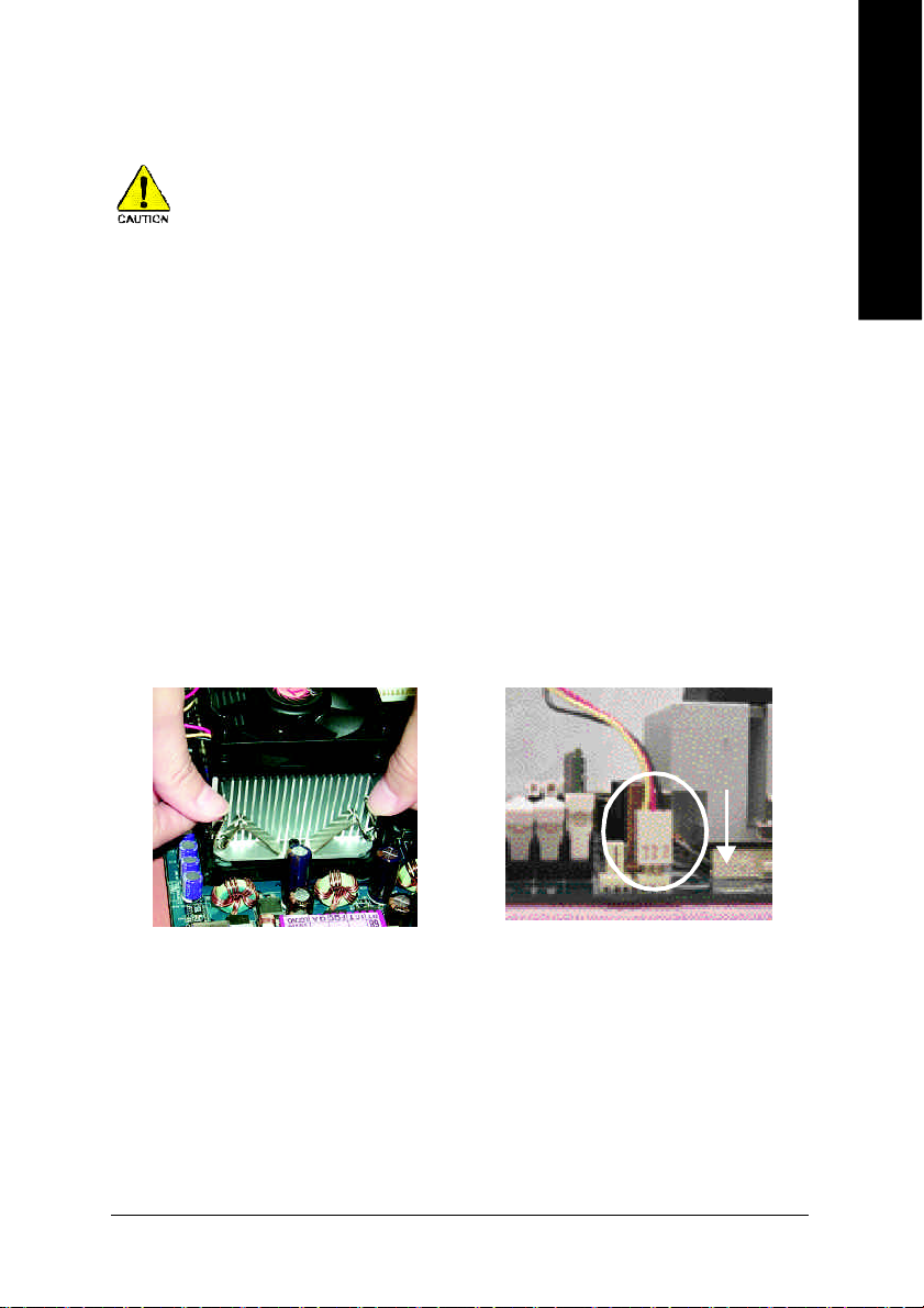
Step 1-2: CPU Cooling Fan Installation
Before installing the CPU cooling fan, adhere to the following warning:
1. Please use Intel approved cooling fan.
2. We recommend you to apply the thermal tape to provide better heat
conduction between your CPU and cooling fan.
(The CPU cooling fan might stick to the CPU due to the hardening of
the thermal paste. During this condition if you try to remove the cool-
ing fan, you might pull the processor out of the CPU socket alone with
the cooling fan, and might damage the processor. To avoid this from
happening, we suggest you to either use thermal tape instead of
thermal paste, or remove the cooling fan with extreme caution.)
3. Make sure the CPU fan power cable is plugged in to the CPU fan
connector, this completes the installation.
Please refer to CPU cooling fan user's manual for more detail
installation procedure.
English
1. Fasten the cooling fan supporting-
base onto the CPU socket on the
motherboard.
2. Make sure the CPU fan is plugged
to the CPU fan connector, than
install complete.
- 13 - Hardware Installation Proc ess
Page 18
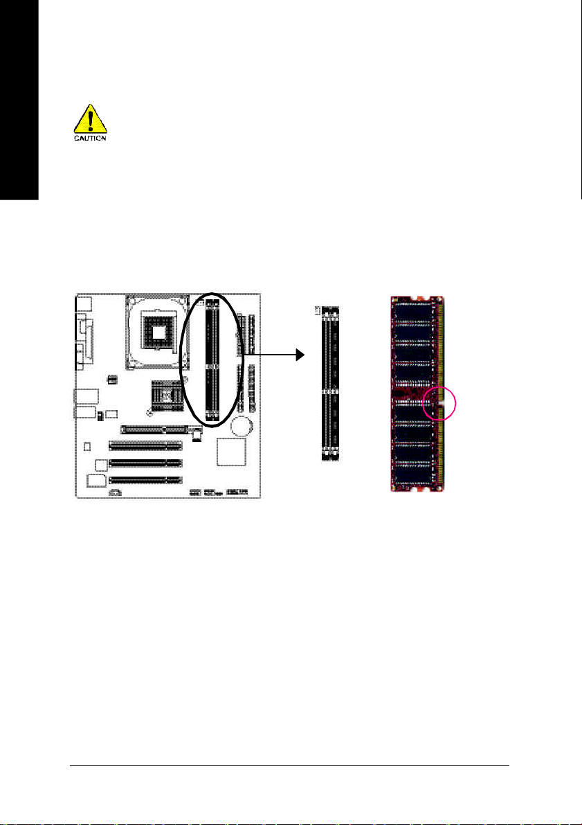
Step 2: Install Memory Modules
English
The motherboard has 2 dual inline memory module (DIMM) sockets. The BIOS will automatically
detects memory type and size. To install the memory module, just push it vertically into the DIMM
socket. The DIMM module can only fit in one direction due to the notch. Memory size can vary
between sockets.
Before installing the memory modules, adhere to the following warning:
1. Please note that the DIMM module can only fit in one direction due to
the one notch. Wrong orientation will cause improper installation.
Please change the insert orientation.
Notch
DDR
- 14 -GA-8VM533 Motherboard
Page 19
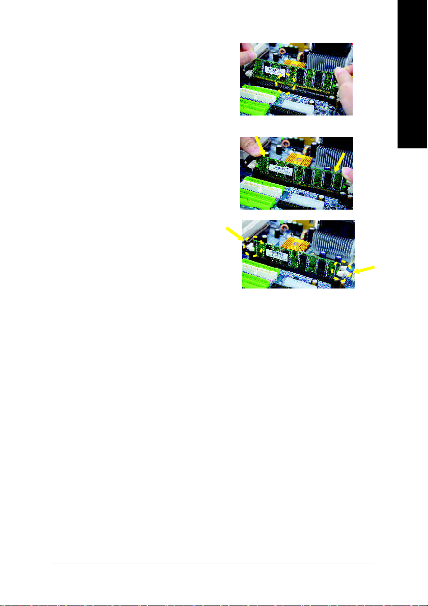
1. The D IMM slot has a notch, so the DIMM
mem ory modu le can only fit in one direction.
2. Insert the DIM M mem ory m odule vertically into
the DIMM slot. Then push it down.
3. Close the plastic clip at both edges of the DIMM
slots to lock the DIMM m odule.
Rever se the in stallation steps when you wish
to remove the DIMM module.
DDR Introduction
English
Established on the existing SDRAM infrastructure, DDR (Double Data Rate) memory is a high
performance and cost-effective solution that allows easy adoption for memory vendors, OEMs,
and system integrators.
DDR memory is a great evolutionary solution for the PC industry that builds on the existing
SDRAM architecture, yet make the awesome advances in solving the system performance
bottleneck by doubling the memory bandwidth. Nowadays, with the highest bandwidth of
3.2GB/s of DDR400 memory and complete line of DDR400/333/266/200 memory solutions, DDR
memory is the best choice for building high performance and low latency DRAM subsystem that
are suitable for servers, workstations, and full range of desktop PCs.
- 15 - Hardware Installation Proc ess
Page 20
Step 3: Install expansion cards
1. Read the related expansion card's instruction document before install the expansion card into the
English
2. Remove your computer's chassis cover, screws and slot bracket from the computer.
3. Press the expansion card firmly into expansion slot in motherboard.
4. Be sure the metal contacts on the card are indeed seated in the slot.
5. Replace the screw to secure the slot bracket of the expansion card.
6. Replace your computer's chassis cover.
7. Power on the computer, if necessary, setup BIOS utility of expansion card from BIOS.
8. Install related driver from the operating system.
computer.
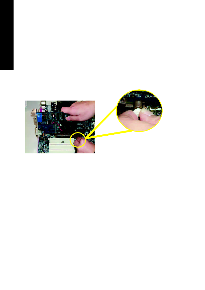
AGP Card
Please carefully pull out the small whitedrawable bar at the end of the AGP slot when
you try to install/ Uninstall the AGP card.
Please align the AGP card to the onboard
AGP slot and press firmly down on the slot .
Make sure your AGP card is locked by the
small white- drawable bar.
- 16 -GA-8VM533 Motherboard
Page 21
Step 4: Connect ribbon cables, cabinet wires and
power supply
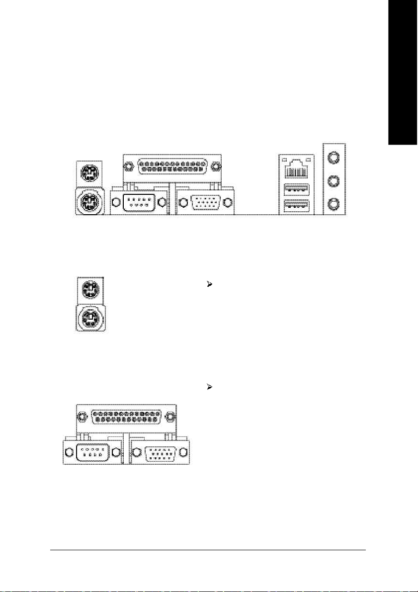
Step 4-1: I/O Back Panel Introduction
English
u
v w
u PS/2 Keyboard and PS/2 Mouse Connector
PS/2 Mouse Connector
(6 pin Female)
PS/2 Keyboard Connector
(6 pin Female)
This connector supports standard PS/2
keyboard and PS/2 mouse.
v Parallel Port, Serial Port and VGA Port (LPT/COMA/VGA)
Parallel Port
(25 pin Female)
This connector supports 1 standard COM
port, 1 Parallel port and 1 VGA port. Device
like printer can be connected to Parallel port;
mouse and modem etc can be connected
to Serial ports.
x
COMA
Serial Port
(9 pin Male)
VGA
VGA Port
(15 pin Female)
- 17 - Hardware Installation Proc ess
Page 22
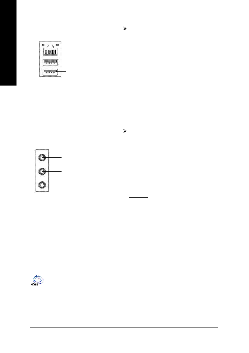
w USB / LAN Connector
English
LAN
USB 0
USB 1
Before you connect your device(s) into USB
connector(s), please make sure your
device(s) such as USB keyboard,mouse,
scanner, zip, speaker..etc. Have a standard
USB interface. Also make sure your OS
supports USB controller.
If your OS does not support USB controller,
please contact OS vendor for possible patch
or driver upgrade. For more information
please contact your OS or device(s) vendors.
x Audio Connectors
Line In(Rear Speaker)
Line Out(Front Speaker)
MIC In(Center and Subwoofer)
If you want the detail information for 6-channel audio setup
installation, please refer to page 68.
After install onboard audio driver, you may
connect speaker to Line Out jack, microphone to
MIC In jack. Device like CD-ROM,walkman etc.
can be connected to Line-In jack.
Please note:
You are able to use 2-/6-channel audio feature by
S/W selection.
If you want to enable 6-channel function, you
have 1 choose for hardware connection.
Method1:
Connect "Front Speaker" to "Line Out"
Connect "Rear Speaker" to "Line In"
Connect "Center and Subwoofer" to "MIC Out ".
- 18 -GA-8VM533 Motherboard
Page 23
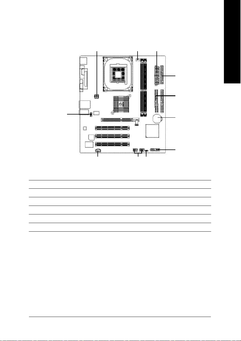
Step 4-2: Connectors Introduction
English
1
9
10 11
3
2
8
1) ATX_12V 7) F_PANEL
2) ATX 8) PWR_LED
3) CPU_FAN 9) F_AUDIO
4) FDD 10) CD_IN
5) IDE1 / IDE2 11) F_USB1 / F_USB2
6) BAT
4
5
6
7
- 19 - Hardware Installation Proc ess
Page 24
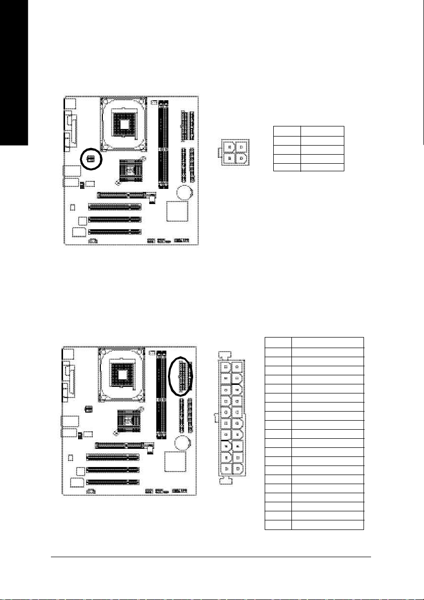
1) ATX_12V (+12V Power Connector)
English
This c onnector (ATX_12 V) supp lies the CPU operation voltage (Vcore ).
If this "ATX_1 2V connec tor" is no t connected, sy stem c annot boot.
4
321
Pin No. Definition
1 GND
2 GND
3 +12V
4 +12V
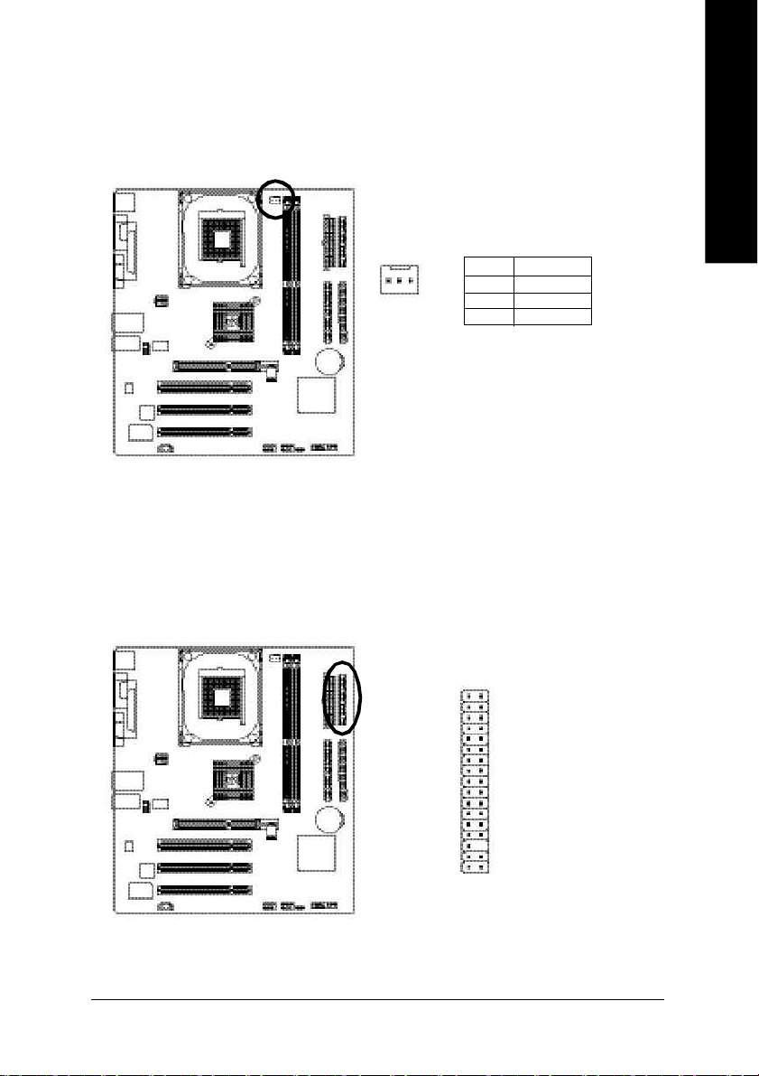
2) ATX (ATX Power)
AC p ower co rd shou ld o nly be connected to your power sup ply u nit after ATX po wer cab le and
other rela ted devices ar e firmly connected to the m ainboard.
Pin No. Definition
1 3.3V
11
20
2 3.3V
1
3 GND
4 VCC
5 GND
6 VCC
7 GND
8 Power Good
9 5V SB (stand by +5V)
10 +12V
11 3.3V
12 -12V
13 GND
14 PS_ON(soft on/off)
10
15 GND
16 GND
17 GND
18 -5V
19 VCC
20 VCC
- 20 -GA-8VM533 Motherboard
Page 25
3) CPU_FAN (CPU Fan Connector)
Pleas e note, a proper ins tallation of the CPU cooler is essential to prevent the CPU from running
unde r abnor mal condi tion or dama ged by overhea ting. T he CPU fan connector supports Max.
current up to 600 m A.
Pin No. Definition
1
1 GND
2 +12V
3 Sense
4) FDD (Floppy Connector)
Pleas e connect the floppy drive ribbon cables to FD D. It supports 36 0K, 1.2M , 720K, 1.44M a nd
2.8 8M b ytes flo ppy di sk typ es.
The r ed stripe of the ribbon ca ble mu st be the sam e side with the Pin1.
English
3334
1
2
- 21 - Hardware Installation Proc ess
Page 26
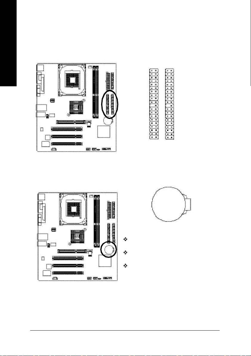
5) IDE1 / IDE2 (IDE1 / IDE2 Connector)
English
6) BAT (BATTERY)
Impor tant Notice:
Pleas e connect first hard disk to IDE1 and c onnect CD-ROM to IDE2.
The r ed stripe of the ribbon ca ble mu st be the sam e side with the Pin1.
IDE2
IDE1
3940
12
+
CAUTION
Da nger o f ex plos ion if batte ry is inco rre ctly
replace d.
Repl ace only with the s am e o r equ ivalent type
recom mended b y the manufacturer.
Di spo se of use d b atter ies ac cor din g to the
ma nufacturer's instruc tions.
If you want to e rase CMO S...
1. Turn OFF the computer and unplug the power cord.
2. R em ov e the b attery, wait for 30 secon d.
3. R e-install the b attery.
4. Pl ug the power cord and turn ON the c omputer.
- 22 -GA-8VM533 Motherboard
Page 27
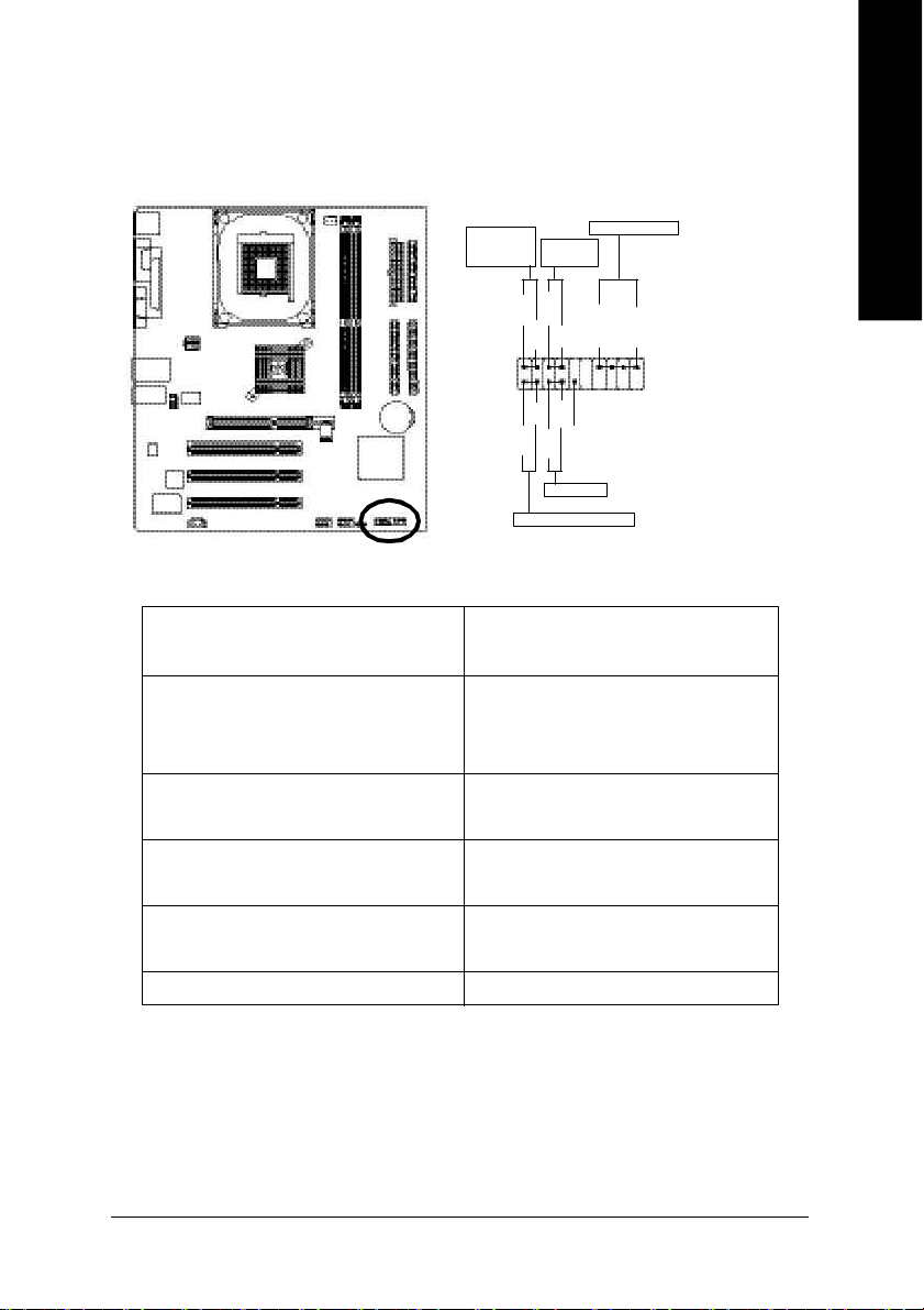
7) F_PANEL (2 x 10 pins Connector)
Please co nnect the power LED, PC speaker, reset switch and power switch etc of your chassisfron t
panel to the F_PANEL conn ector accordi ng to the pin assignm ent above.
English
Messa ge L ED/
Po wer/
Slee p LED
1 1
2
1
1
IDE H ard Disk Acti ve LE D
Sof t Po wer
Connect or
MSG+
MSG-
HD-
HD+
Res et Swi tch
PW+
RES-
PW-
1
RES+
NC
Speak er Co nnector
SPEAK+
SPEAK-
1
2 0
1 9
HD (IDE Hard Disk Active LED) Pin 1: LED anode(+)
Pin 2: LED cathode(-)
SPEAK (Speaker Connector) Pin 1: VCC(+)
Pin 2- Pin 3: NC
Pin 4: Data(-)
RES (Reset Switch) Open: Normal Operation
Close: Reset Hardware System
PW (Soft Power Connector) Open: Normal Operation
Close: Power On/Off
MSG(Message LED/ Power/ Sleep LED) Pin 1: LED anode(+)
Pin 2: LED cathode(-)
N C N C
- 23 - Hardware Installation Proc ess
Page 28
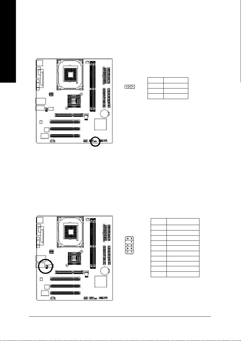
8) PWR_LED
English
9) F_AUDIO (Front Audio Connector)
PWR_ LED is connect with the system power indic ator to i ndicate whethe r the s ystem is on/ off.
It will blin k when the system enters su spend mode . If you use dual color LED, power L ED will turn
to another colo r.
Pin No. Definition
1
In order to utilize the fron t audio heade r, you r chassis must have front audio connector. Al so
please make s ure the pin assigm ent on the cab le is the sam e as the pin assigm ent on the M B
heade r. To find o ut if the chass is you ar e buying support front au dio conne ctor, please contact
your d ealer. Plea se note, yo u can have the alternative of usi ng front audio conn ector or of usi ng
rear a udio conne ctor to play sound.
1 MPD+
2 MPD3 MPD-
Pin No. Definition
1 MIC
2 GND
10
9
1
2
- 24 -GA-8VM533 Motherboard
3 REF
4 Power
5 Front Audio (R)
6 Rear Audio (R)
7 Reserved
8 No Pin
9 Front Audio (L)
10 Rear Audio (L)
Page 29
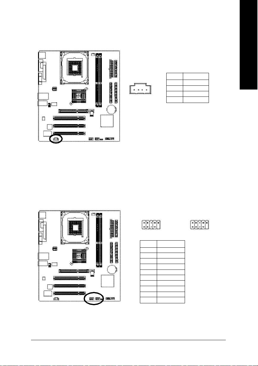
10) CD_IN (CD In Connector)
Connec t CD-ROM or DVD-ROM audio out to the connector.
Pin No. Definition
1 CD-L
1
2 GND
3 GND
4 CD-R
11) F_USB1 / F_USB2 (Front USB Connector, Yellow)
Be c areful with the polarity o f the front USB connector. Check the pin assignm ent while you
conne ct the front USB ca ble. Pleas e contact your nearest de aler for optiona l front USB c able.
English
10
2
F_US B1
F_US B2
1 9
Pin No. Definition
1 Power
2 Power
3 USB Dx4 USB Dy5 USB Dx+
6 USB Dy+
7 GND
8 GND
9 No Pin
10 NC
- 25 - Hardware Installation Proc ess
2
1 9
10
Page 30

English
- 26 -GA-8VM533 Motherboard
Page 31

Chapter 3 BIOS Setup
BIOS Setup is an overview of the BIOS Setup Program. The program that allows users to modify the
basic system configuratio n. This type of information is stored in battery-backed CM OS RAM so that it
retains the Setup information when the power is turned off.
ENTERING SETUP
After power on the computer, pressing <Del> immediately during POST (Power On Self Test) it w ill allow
you to enter standard BIOS CMOS SETUP.
If you require more adv anced B IOS settings, please go to "Adv anc ed BIOS" setting menu.To enter
Advanced BIOS setting menu, press "Ctrl+F1" key on the BIOS screen.
CONTROL KEYS
<á> Move to previous item
<â> Move to next item
<ß> Move to the item in the left hand
<à> Move to the item in the right hand
Enter Select item
<Esc> Main M enu - Quit and not save changes into CM OS Status Page Setup Menu and
Option Page Setup Menu - Exit current page and return to Main Menu
<+/PgUp> Increase the numeric value or make changes
<-/PgDn> Decrease the numeric value or make changes
<F1> General help, only for Status Page Setup Menu and Option Page Setup Menu
<F2> Item Help
<F3> Reserved
<F4> Reserved
<F5> Restore the previous CMOS value from CMOS, only for Option Page Setup Menu
<F6> Load the file-safe default CMOS value from BIOS default table
<F7> Load the Optimized Defaults
<F8> Q-Flash function
<F9> System Information
<F10> Sav e all the CM OS changes, only for Main Menu
English
- 27 -
BIOS Setup
Page 32

G ETTING HELP
The on-line description of the highlighted setup function is displayed at the bottom of the screen.
English
Press F1 to pop up a small help win dow that descr ibes the appro priate keys to use and the possible
selections for the highlighted item. To ex it the Help Window press <Esc>.
The Main Menu (For example: BIOS Ver. : F1)
Once you enter Award BIOS CM OS Setup Utility, the Main Menu (Figure 1) will appear on the screen.
The Main Menu allows you to select from eight setup functions and two exit choices. U se arrow key s to
select among the items and press <Enter> to accept or enter the sub-menu.
Main Menu
Status Page Setup Menu / Op tion Page Setup M enu
CMOS Setup Utility -Copy right (C) 1984-2003 Award Software
}Standard CMOS Features Load Fail-Safe Defaults
}Advanced BIOS Features Load Optimized Defaults
}Integrated Peripherals Set Supervisor Passw ord
}Power Management Setup Set User Password
}PnP/PCI Configurations Sav e & Ex it Setup
}PC Health Status Exit Without Saving
}Frequency/Voltage Control
ESC:Quit higf: Select Item
F8:Q-Flash F10:Save & Exit Setup
Time, Date, Hard Disk Type...
Figure 1: Main Menu
If you can't find the setting you want, please press "Ctrl+F1" to
search the advanced option widden.
l Standard CMOS Features
This setup page includes all the items in standard compatible BIOS.
l Advanced BIOS Features
This setup page includes all the items of Award special enhanced features.
- 28 -GA-8VM533 Motherboard
Page 33

l Integrated Peripherals
This setup page includes all onboard peripherals.
l Power Manag ement Setup
This setup page includes all the items of Green function features.
l PnP/PCI Configurations
This setup page includes all the configurations of PC I & PnP ISA resources.
l PC Health Status
This setup page is the Sy stem auto detect Temperature, voltage, fan, speed.
l Frequency/Voltage Control
This setup page is control C PU's clock and frequency ratio.
l Load Fail-Safe Defaults
Fail-Safe Defaults indicates the value of the sy stem parameters which the system would
be in safe configuration.
l Load Optimized Defaults
Optimized Defaults indicates the value of the sy stem parameters which the system would
be in better performance configuration.
l Load Top Performance Defaults
Top Performance Defaults indicates the v alue of the system parameters which the system
would be in best performance configuration.
l Set Supervisor password
Change, set, or disable password. It allows you to limit access to the system and Setup,
or just to Setup.
l Set User password
Change, set, or disable password. It allows you to limit access to the system.
l Save & Exit Setup
Save CMOS value settings to CM OS and exit setup.
l Exit Without Saving
Abandon all CMOS value changes and exit setup.
English
- 29 -
BIOS Setup
Page 34

Standard CMOS Features
English
CMOS Setup Utility -Copy right (C) 1984-2003 Award Software
Standard CMOS Features
Date (mm:dd:yy) Tue, Aug 13 2002 Item Help
Time (hh:mm:ss) 22:31:24 Menu Level u
Change the day, month,
}IDE Primary Master [None] y ear
}IDE Primary Slave [None]
}IDE Secondary Master [None] <Week>
}IDE Secondary Slave [None] Sun. to Sat.
Drive A [1.44M, 3.5 in.] <Month>
Drive B [None] Jan. to Dec.
Floppy 3 Mode Support [Disabled]
<Day>
Halt On [All, But Keyboard] 1 to 31 (or maximum
allowed in the month)
Base Memory 640K
Extended Memory 130048K <Year>
Total Memory 131072K 1999 to 2098
higf: Move Enter:Select +/-/PU/PD:Value F10:Save ESC:Ex it F1:General Help
F5:Previous Values F6:Fail-Safe Defaults F7:Optimized Defaults
Figure 2: Standard CMOS Features
Date
The date format is <week>, <month>, <day>, <y ear>.
Week The week, from Sun to Sat, determined by the BIOS and is display only
Month The month, Jan. Through Dec.
Day The day, from 1 to 31 (or the maximum allow ed in the month)
Year The year, from 1999 through 2098
Time
The times format in <hour> <minute> <second>. The time is calculated base on the 24-hour
military-time clock. For example, 1 p.m. is 13:00:00.
- 30 -GA-8VM533 Motherboard
Page 35

IDE Primary Master, Slave / Secondary M aster, Slave
The category identifies the types of hard disk from driv e C to F that has been installed in the
computer. There are two types: auto type, and manual type. Manual type is user-definable; Auto
type which will automatically detect HDD type.
Note that the specifications of your drive must match with the drive table. The hard disk w ill not work
properly if you enter improper information for this category .
If you select User Ty pe, related information will be asked to enter to the following items. Enter the
information directly from the keyboard and press <Enter>. Such information should be provided in
the documentation form your hard disk v endor or the system manufacturer.
Capacity: The hard disk size. The unit is M ega Bytes.
Access Mode: The options are: Auto / Large / LBA / Normal.
Cylinder: The cylinder number of hard disk.
Head The read / Write head number of hard disk.
Precomp The cyliner number at which the disk driver changes the write current.
Landing Zone The cylinder number that the disk driver heads(read/write) are seated when
the disk drive is parked.
SECTORS The sector number of each track define on the hard disk.
If a hard disk has not been installed select NON E and press <Enter>.
Drive A / Drive B
The category identifies the types of floppy disk driv e A or drive B that has been installed in the
computer.
None N o floppy driv e installed
360K, 5.25". 5.25 inch PC-type standard drive; 360K byte capacity.
1.2M, 5.25". 5.25 inch AT-type high-density drive; 1.2M byte capacity
(3.5 inch when 3 Mode is Enabled).
720K, 3.5". 3.5 inch double-sided driv e; 720K by te capacity
1.44M, 3.5". 3.5 inch double-sided drive; 1.44M byte capacity .
2.88M, 3.5". 3.5 inch double-sided drive; 2.88M byte capacity .
English
- 31 -
BIOS Setup
Page 36

English
The category is display-only which is determined by POST (Power On Self Test) of the BIOS.
Floppy 3 Mode Support (for Japan Area)
Disabled N ormal Floppy Driv e. (Default value)
Drive AA Enabled 3 mode function of Driv e A.
Drive B Enabled 3 mode function of Driv e B.
Both Drive A & B are 3 mode Floppy Drives.
H alt on
The category determines whether the computer will stop if an error is detected during pow er up.
NO Errors The system boot will not stop for any error that may be detected
and you will be prompted.
All Errors Whenever the BIOS detects a non-fatal error the system will be
stopped.
All, But Keyboar The system boot will not stop for a key board error; it will stop for
all other errors. (Default v alue)
All, But Diskette The system boot will not stop for a disk error; it will stop for all
other errors.
All, But Disk/Key The system boot w ill not stop for a keyboard or disk error; it will
stop for all other errors.
M emory
Base Memory
The POST of the BIOS will determine the amount of base (or conv entional) memory
installed in the system.
The value of the base memory is typically 512 K for systems with 512 K memory
installed on the motherboard, or 640 K for systems with 640 K or more memory
installed on the motherboard.
Extended Memory
The BIOS determines how much extended memory is present during the POST.
This is the amount of memory located above 1 M B in the C PU's memory
address map.
- 32 -GA-8VM533 Motherboard
Page 37

Advanced BIOS Features
CMOS Setup Utility -Copy right (C) 1984-2003 Award Software
Advanced BIOS Features
First Boot Dev ice [Floppy] Item Help
Second Boot Device [HDD-0] Menu Level u
Third Boot Device [CD-ROM] Select Boot Dev ice
Password Check [Setup] priority
# CPU Hy per-Threading [Enabled] [Floppy ]
Boot from floppy
[LS120]
Boot from LS120
[HDD-0]
Boot from First HDD
[HDD-1]
Boot from second HDD
higf: Move Enter:Select +/-/PU/PD:Value F10:Save ESC:Ex it F1:General Help
F5:Previous Values F6:Fail-Safe Defaults F7:Optimized Defaults
Figure 3: Advanced BIOS Features
" # " System will detect automatically and show up when you install the Intel
with HT Technology.
First / Second / Third Boot device
M This feature allows y ou to select the boot device priority.
Floppy Select your boot device priority by Floppy.
LS120 Select your boot device priority by LS120.
HDD-0~3 Select your boot device priority by HDD-0~3.
SCSI Select your boot device priority by SC SI.
CDROM Select your boot device priority by CDROM .
LAN Select your boot device priority by LAN.
USB-CDROM Select your boot device priority by USB-CDROM .
USB-ZIP Select y our boot device priority by USB-ZIP.
USB-FDD Select your boot device priority by USB-FDD.
®
Pentium
®
4 processor
English
- 33 -
BIOS Setup
Page 38

English
USB-HDD Select your boot device priority by U SB-H DD.
ZIP Select your boot device priority by ZIP.
Disabled Disable this function.
Password Check
Setup The system will boot but w ill not access to Setup page if the correct
password is not entered at the prompt. (Default v alue)
System The system will not boot and w ill not access to Setup page if the correct
password is not entered at the prompt.
CPU Hyp er-Threading
Enabled Enables CPU Hyper Threading Feature. Please note that this feature is only
working for operating system with multi processors mode supported.
(Default v alue)
Disabled Disables CPU Hy per Threading.
- 34 -GA-8VM533 Motherboard
Page 39

Integrated Peripherals
CMOS Setup Utility -Copy right (C) 1984-2003 Award Software
Integrated Peripherals
OnChip IDE Channel0 [Enabled] Item Help
OnChip IDE Channel1 [Enabled] Menu Level u
AC97 Audio [Auto] If a hard disk
VIA onboard LAN [Enabled] controller card is
USB 1.1 Controller [Enabled] used, set at Disabled
USB 2.0 Controller [Enabled]
USB Keyboard Support [Disabled] [Enabled]
USB Mouse Support [Disabled] Enable onboard IDE
Onboard Serial Port 1 [3F8/IRQ4] Channel
Onboard Parallel Port [378/IRQ7]
Parallel Port Mode [SPP] [Disabled]
Disable onboard IDE
Channel
higf: Move Enter:Select +/-/PU/PD:Value F10:Save ESC:Ex it F1:General Help
F5:Previous Values F6:Fail-Safe Defaults F7:Optimized Defaults
English
Figure 4: Integrated Peripherals
- 35 -
BIOS Setup
Page 40

M When enabled, allow s you to use the onboard primary PCI IDE. If a hard disk controller card is
used, set at Disabled.
English
M When enabled, allows y ou to use the onboard secondary PCI IDE. If a hard disk controller card is
used, set at Disabled.
M Disable this option if you are not using the onboard U SB feature.
OnChip IDE Channel0
Enabled Enable onboard 1st channel IDE port. (Default value)
Disabled Disable onboard 1st channel IDE port.
OnChip IDE Channel1
Auto Enable onboard 2nd channel IDE port. (Default value)
Disabled Disable onboard 2nd channel IDE port.
AC97 Aud io
Auto Enable onboard AC'97 audio function. (Default Value)
Disabled Disable this function.
VIA onboard LAN
Enable Enable onboard LAN function.(Default value)
Disable Disable onboard LAN function.
U SB 1.1 Controller
Enabled Enable USB1.1 Controller. (Default v alue)
Disabled Disable U SB1.1 Controller.
U SB 2.0 Controller
M Disable this option if you are not using the onboard U SB 2.0 feature.
Enabled Enable USB 2.0 Controller. (Default v alue)
Disabled Disable U SB 2.0 Controller.
U SB Keyboard Support
M When a USB key board is installed, please set at Enabled.
Enabled Enable USB Keyboard Support.
Disabled Disable U SB Keyboard Support. (Default value)
- 36 -GA-8VM533 Motherboard
Page 41

U SB Mouse Support
Enabled Enable USB Mouse Support.
Disabled Disable U SB Mouse Support. (Default value)
Onb oard Ser ial Port 1
Auto BIOS will automatically setup the port 1 address.
3F8/IRQ4 Enable onboard Serial port 1 and address is 3F8,Using IRQ4. (Default value)
2F8/IRQ3 Enable onboard Serial port 1 and address is 2F8,Using IRQ3.
3E8/IRQ4 Enable onboard Serial port 1 and address is 3E8,Using IRQ4.
2E8/IRQ3 Enable onboard Serial port 1 and address is 2E8,Using IRQ3.
Disabled Disable onboard Serial port 1.
OnBoard Parallel port
M This feature allows you to select from a given set of parameters if the parallel port uses the onboard
I/O controller.
378/IRQ7 Enable onboard LPT port and address is 378, U sing IRQ7.(Default Value)
278/IRQ5 Enable onboard LPT port and address is 278,U sing IRQ5.
3BC/IRQ7 Enable onboard LPT port and address is 3BC,Using IRQ7.
Disabled Disable onboard parallel port.
English
Parallel Port Mode
M This feature allows you to connect with an advanced print via the port mode it supports.
SPP Using Parallel port as Standard Parallel Port using IRQ7. (Default Value)
EPP Using Parallel port as Enhanced Parallel Port IRQ5.
ECP Using Parallel port as Extended Capabilities Port using IRQ7.
ECP+EPP Using Parallel port as ECP & EPP mode.
- 37 -
BIOS Setup
Page 42

Power Management Setup
English
ACPI Suspend Type [S1(POS)] Item Help
x USB Dev ice Wake-Up From S3 Disabled Menu Level u
Soft-Off by PWRBTN [Instant-off] [S1]
AC Back Function [Soft-Off] Set suspend ty pe to
Keyboard Power On [Disabled] Power On Suspend under
Mouse Power On [Disabled] ACPI OS
PME Event Wake Up [Enabled]
Modem Ring Resume [Enabled] [S3]
Resume by Alarm [Disabled] Set suspend type to
x Date(of Month) Alarm Ev ery day Suspend to RAM under
x Time(hh:mm:ss) Alarm 0 : 0 : 0 ACPI OS
higf: Move Enter:Select +/-/PU/PD:Value F10:Save ESC:Ex it F1:General Help
CMOS Setup Utility -Copy right (C) 1984-2003 Award Software
Power Management Setup
F5:Previous Values F6:Fail-Safe Defaults F7:Optimized Defaults
Figure 5: Power Management Setup
ACPI Suspend Type
S1/POS Set suspend type to Power On Suspend under ACPI OS
(Power On Suspend). (Default value)
S3/STR Set suspend ty pe to Suspend To RAM under ACPI OS (Suspend To RAM).
U SB Device Wakeup From S3(When ACPI Suspend Type i s set [S3/STR])
USB device wakeup From S3 can be set when ACPI standby state set to S3/STR.
Enabled USB Device can wakeup system from S3.
Disabled U SB Device can't wakeup system from S3. (Default value)
- 38 -GA-8VM533 Motherboard
Page 43

Soft-off by PWRBTNN
Instant-off Press power button then Power off instantly. (Default value)
Delay 4 Sec. Press power button 4 sec to Power off. Enter suspend if button is
pressed less than 4 sec.
AC Back Function
Memory Sy stem power on depends on the status before AC lost.
Soft-Off Alw ays in Off state when AC back. (Default value)
Full-On Always power on the system when AC back.
K eyboard Power On
This feature allow s you to set the method for powering-on the system.
The option "Password" allows you to set up to 8 alphanumeric characters to power-on the system.
The option "Keyboard 98" allows you to use the standard keyboard 98 to power on the system.
Password Enter from 1 to 8 characters to set the Keyboard Power On Password.
Disabled Disabled this function. (Default v alue)
Keyboard 98 If your keyboard have " POWER Key" button, y ou can press the
key to power on your system.
M ouse Pow er On
Disabled C an't Power on sy stem by M ouse Event. (Default value)
Enabled Can Power on system by Mouse Event.
English
PME Event Wake up
M When set at Enabled, any PCI-PM ev ent awakes the system from a PCI-PM controlled
state.
M This feature requires an ATX power supply that prov ides at least 1A on the +5VSB lead.
Disabled Disable PM E Ev ent Wake up function.
Enabled Enable PME Event Wake up function. (Default Value)
- 39 -
BIOS Setup
Page 44

English
Resume by Alarm
M odem Ring Resume
Disabled Disable M odem Ring Resume function.
Enabled Enable Modem Ring On Resume function. (Default Value)
You can set "Resume by Alarm" item to enabled and key in Data/time to power on system.
Disabled Disable this function. (Default Value)
Enabled Enable alarm function to POWER ON system.
If RTC Alarm Lead To Power On is Enabled.
Date ( of Month) Alarm : Every day , 1~31
Time ( hh: mm: ss) Alarm :(0~23) : (0~59) : (0~59)
- 40 -GA-8VM533 Motherboard
Page 45

PnP/PCI Configurations
CMOS Setup Utility -Copy right (C) 1984-2003 Award Software
PnP/PCI Configurations
PCI 1 IRQ Assignment [Auto] Item Help
PCI 2 IRQ Assignment [Auto] Menu Level u
PCI 3 IRQ Assignment [Auto] Decice(s) using this
INT:
USB 1.1 Host Cntrlr
- Bus 0 Dev16 Func 1
higf: Move Enter:Select +/-/PU/PD:Value F10:Save ESC:Ex it F1:General Help
F5:Previous Values F6:Fail-Safe Defaults F7:Optimized Defaults
Figure 6: PnP/PCI Configurations
PCI1 IRQ Assignment
Auto Auto assign IRQ to PCI 1. (Default value)
3,4,5,7,9,10,11,12,14,15 Set 3,4,5,7,9,10,11,12,14,15 to PCI1.
English
PCI2 IRQ Assignment
Auto Auto assign IRQ to PCI 2. (Default value)
3,4,5,7,9,10,11,12,14,15 Set 3,4,5,7,9,10,11,12,14,15 to PCI2.
PCI3 IRQ Assignment
Auto Auto assign IRQ to PCI 3. (Default value)
3,4,5,7,9,10,11,12,14,15 Set 3,4,5,7,9,10,11,12,14,15 to PCI3.
- 41 -
BIOS Setup
Page 46

PC Health Status
English
Vcore 1.520V Item Help
DDR25V 2.480V Menu Level u
+3.3V 3.280V
+12V 11.968V
Current CPU Temperature 45°C
Current CPU FAN Speed 4440RPM
CPU FAN Fail Warning [Disabled]
higf: Move Enter:Select +/-/PU/PD:Value F10:Save ESC:Ex it F1:General Help
CMOS Setup Utility -Copy right (C) 1984-2003 Award Software
PC Health Status
F5:Previous Values F6:Fail-Safe Defaults F7:Optimized Defaults
Figure7: PC Health Status
Current V oltage (V) Vcore / DDR25V / +3.3V / +12V
Detect system's voltage status automatically.
Current CPU Temp eraturee
Detect CPU Temp. automatically..
Current CPU FAN Sp eed (RPM)
Detect Fan speed status automatically.
CPU Fan Fail Warning
Disabled Don't monitor current fan speed. (Default value)
Enabled Alarm when stops.
- 42 -GA-8VM533 Motherboard
Page 47

Frequency/Voltage Control
CMOS Setup Utility -Copy right (C) 1984-2003 Award Software
Frequency/Voltage Control
CPU Clock Ratio [15X] Item Help
Auto Detect PCI/DIMM Clk [Enabled]
Spread Spectrum [+/-0.25%]
CPU Clock [100]
higf: Move Enter:Select +/-/PU/PD:Value F10:Save ESC:Ex it F1:General Help
F5:Previous Values F6:Fail-Safe Defaults F7:Optimized Defaults
Figure 8: Frequency/Voltage Control
CPU Clock Ratio
This option will not be shown or not be available if you are using a CPU w ith the locked ratio.
15X~21X It depends on CPU Clock Ratio.
This setup option will automatically assign by CPU detection.
For C-Stepping P4: 8X,10X~24X default: 15X
For Northwood CPU: 12X~24X default: 16X
The option w il l display "Locked" and read only if the CPU ratio is not changeable.
English
Auto Detect PCI/DIMM Clk
Disabled Disable auto detect PCI/DIMM Clk.
Enabled Enable auto detect PC I/DIMM Clk. (Default v alue)
Sp read Spectrum
Disabled Disable clock spread spectrum.
- 1.50% Set Spread Spectrum to - 1.50% .
- 1.00% Set Spread Spectrum to - 1.00% .
- 0.70% Set Spread Spectrum to - 0.70% .
- 0.50% Set Spread Spectrum to - 0.50% .
- 43 -
BIOS Setup
Page 48

English
+/- 0.75% Set Spread Spectrum to +/- 0.75% .
+/- 0.50% Set Spread Spectrum to +/- 0.50% .
+/- 0.35% Set Spread Spectrum to +/- 0.35% .
+/- 0.25% Set Spread Spectrum to +/- 0.25% .
CPU Clock
100 Set CPU Clock to 100MHz~132M H z.
133 Set CPU Clock to 133MHz~165M H z.
Incorrect using it may cause your system broken. For power End-User use only!
- 44 -GA-8VM533 Motherboard
Page 49

Load Fail-Safe Defaults
CMOS Setup Utility -Copy right (C) 1984-2003 Award Software
}Standard CMOS Features Load Fail-Safe Defaults
}Advanced BIOS Features Load Optimized Defaults
}Integrated Peripherals Set Supervisor Passw ord
}Power Management Setup Set User Password
}PnP/PCI Configurations Sav e & Ex it Setup
}PC Health Status Exit Without Saving
}Frequency/Voltage Control
ESC:Quit higf: Select Item
F8:Q-Flash F10:Save & Exit Setup
Figure 11: Load Fail-Safe Defaults
Load Fail-Safe Defaults
Fail-Safe defaults contain the most appropriate v alues of the system parameters that allow
minimum system performance.
Load Fail-Safe Defaults? (Y/N)?N
Load Fail-Safe Defaults
Figure 9: Load Fail-Safe Defaults
English
- 45 -
BIOS Setup
Page 50

Load Optimized Defaults
English
system automatically detects.
CMOS Setup Utility -Copy right (C) 1984-2003 Award Software
}Standard CMOS Features Load Fail-Safe Defaults
}Advanced BIOS Features Load Optimized Defaults
}Integrated Peripherals Set Supervisor Passw ord
}Power Management Setup Set User Password
}PnP/PCI Configurations Sav e & Ex it Setup
Figure 11: Load Fail-Safe Defaults
}PC Health Status Exit Without Saving
}Frequency/Voltage Control
ESC:Quit higf: Select Item
F8:Q-Flash F10:Save & Exit Setup
Load Optimized Defaults? (Y/N)?N
Load Optimized Defaults
Figure 10: Load Optimized Defaults
Load Optimized Defaults
Selecting this field loads the factory defaults for BIOS and Chipset Features which the
- 46 -GA-8VM533 Motherboard
Page 51

Set Supervisor/User Password
CMOS Setup Utility -Copy right (C) 1984-2003 Award Software
}Standard CMOS Features Load Fail-Safe Defaults
}Advanced BIOS Features Load Optimized Defaults
}Integrated Peripherals Set Supervisor Passw ord
}Power Management Setup Set User Password
}PnP/PCI Configurations Sav e & Ex it Setup
}PC Health Status Exit Without Saving
}Frequency/Voltage Control
ESC:Quit higf: Select Item
F8:Q-Flash F10:Save & Exit Setup
Figure 11: Load Fail-Safe Defaults
When you select this function, the following message will appear at the center of the screen to assist y ou
in creating a password.
Ty p e th e pa ssword, u p to eig ht c hara cters, an d press <Enter>. You w ill be asked to confirm the
password. Ty pe the passw or d aga in and press <Enter>. You may als o pres s <Esc > to abort the
selection and not enter a passw ord.
To disab le passwo rd, just press <Enter> when you a re prompted to enter password. A message
"PASSWORD DISABLED" will appear to confirm the passw ord being disabled. Once the password is
disabled, the system will boot and you can enter Setup freely.
The BIOS Setup program allows you to specify two separate passwords: a SU PERVISOR PASS-
WORD and a USER PASSWORD. When disabled, anyone may access all BIOS Setup program
function. When enabled, the Supervisor passw ord is required for entering the BIOS Setup program and
having full configuration fields, the User password is required to access only basic items.
If you select "Sy stem" at "Security Option" in Advance BIOS Features Menu, y ou w ill be prompted for
the password every time the system is rebooted or any time you try to enter Setup Menu.
If you select "Setup" at "Security Option" in Adv ance BIOS Features Menu, you will be prompted only
when you try to enter Setup.
Enter Password:
Change/Set/Disable Password
Figure 11: Password Setting
English
- 47 -
BIOS Setup
Page 52

Save & Exit Setup
English
Ty pe " Y" will quit the Setup Utility and save the user setup v alue to RTC CMOS.
Ty pe " N" will return to Setup Utility.
CMOS Setup Utility -Copy right (C) 1984-2003 Award Software
}Standard CMOS Features Load Fail-Safe Defaults
}Advanced BIOS Features Load Optimized Defaults
}Integrated Peripherals Set Supervisor Passw ord
}Power Management Setup Set User Password
}PnP/PCI Configurations Sav e & Ex it Setup
}PC Health Status Exit Without Saving
}Frequency/Voltage Control
ESC:Quit higf: Select Item
F8:Q-Flash F10:Save & Exit Setup
Save to CMOS and EXIT (Y/N)? Y
Save Data to CMOS
Figure 12: Save & Exit Setup
- 48 -GA-8VM533 Motherboard
Page 53

Exit Without Saving
CMOS Setup Utility -Copy right (C) 1984-2003 Award Software
}Standard CMOS Features Load Fail-Safe Defaults
}Advanced BIOS Features Load Optimized Defaults
}Integrated Peripherals Set Supervisor Passw ord
}Power Management Setup Set User Password
}PnP/PCI Configurations Sav e & Ex it Setup
}PC Health Status Exit Without Saving
}Frequency/Voltage Control
ESC:Quit higf: Select Item
F8:Q-Flash F10:Save & Exit Setup
Ty pe " Y" will quit the Setup Utility without sav ing to RTC CMOS.
Ty pe " N" will return to Setup Utility.
Quit Without Saving (Y/N)? N
Abandon all Data
Figure 13: Exit Without Saving
English
- 49 -
BIOS Setup
Page 54

English
- 50 -GA-8VM533 Motherboard
Page 55

Chapter 4 Technical Reference
@BIOS™ Introduction
Gigabyte announces @B IOS
Windows BIOS live update utility
Maybe not like others, you are very experienced in BIOS updating and spend quite a lot of time
to do it. But of course you don’t like to do it too much. First, download different BIOS from website and
then switch the operating system to DOS mode. Secondly, use different flash utility to update BIOS.
The above process is not a interesting job. Besides, always be carefully to store the BIOS source code
correctly in your disks as if you update the wrong BIOS, it will be a nightmare.
Certainly, you wonder why motherboard vendors could not just do something right to save your
time and effort and save you from the lousy BIOS updating work? Here it comes! Now Gigabyte
announces @BIOS— the first Windows BIOS live update utility. This is a smart BIOS update software.
It could help you to download the BIOS from internetand update it. Not like the other BIOS update
software, it's a Windows utility. With the help of "@BIOS", BIOS updating is no more than a click.
Besides, no matter which mainboard you are using, if it’s a Gigabyte's product*, @BIOS help you
to maintain the BIOS. This utility could detect your correct mainboard model and help you to choose the
BIOS accordingly. It then downloads the BIOS from the nearest Gigabyte ftp site automatically. There
are several different choices; you could use "Internet Update" to download and update your BIOS
directly. Or you may want to keep a backup for your current BIOS, just choose "Save Current BIOS"
to save it first. You make a wise choice to use Gigabyte, and @BIOS update your BIOS smartly. You
are now worry free from updating wrong BIOS, and capable to maintain and manage your BIOS
easily. Again, Gigabyte's innovative product erects a milestone in mainboard industries.
For such a wonderful software, how much it costs? Impossible! It's free! Now, if you buy a
Gigabyte's motherboard, you could find this amazing software in the attached driver CD. But please
remember, connected to internet at first, then you could have a internet BIOS update from your
Gigabyte @BIOS.
™
Have you ever updated BIOS by yourself? Or like
many other people, you just know what BIOS is,
but always hesitate to update it? Because you think
updating newest BIOS is unnecessary and actually
you don't know how to update it.
English
- 51 -
Technical Reference
Page 56

EasyTune™ 4 Introduction
Gigabyte announces EasyTune
™
4
English
Windows based Overclocking utility
EasyTune 4 carries on the heritage so as to pave the way for future generations.
hardware or BIOS tools to do "Overclock". And even with these technologies, they still learn that it's
quite a risk because the safety and stability of an "Overclock" system is unknown. Now everything
is different because of a Windows based overclocking utility "EasyTune 4" --announced by Gigabyte.
This windows based utility has totally changed the gaming rule of "Overclock". This is the first
windows based overclocking utility is suitable for both normal and power users. Users can choose
either "Easy Mode" or "Advanced Mode" for overclocking at their convenience. For users who
choose "Easy Mode", they just need to click "Auto Optimize" to have autoed and immediate CPU
overclocking. This software will then overdrive CPU speed automatically with the result being shown
in the control panel. If users prefer "Overclock" by them, there is also another choice. Click "Advanced
Mode" to enjoy "sport drive" class Overclocking user interface. "Advanced Mode", allows users to
change the system bus / AGP / Memory working frequency in small increments to get ultimate system
performance. It operates in coordination with Gigabyte motherboards. Besides, it is different from other
traditional over-clocking methods, EasyTune 4 doesn't require users to change neither BIOS nor
hardware switch/ jumper setting; on the other hand, they can do "Overclock" at easy step . Therefore,
this is a safer way for "Overclock" as nothing is changed on software or hardware. If user runs
EasyTune 4 over system's limitation, the biggest lost is only to restart the computer again and the side
effect is then well controlled. Moreover, if one well-performed system speed has been tested in
EasyTune 4, user can "Save" this setting and "Load" it in next time. Obviously, Gigabyte EasyTune
4 has already turned the "Overclock" technology toward to a newer generation. This wonderful
software is now free bundled in Gigabyte motherboard attached in driver CD. Users may make a test
drive of "EasyTune 4" to find out more amazing features by themselves.
*Some Gigabyte products are not fully supported by EasyTune 4. Please find the products supported
list in the web site.
*Any "Overclocking action" is at user's risk, Gigabyte Technology will not be responsible for any
damage or instability to your processor, motherboard, or any other components.
Overclock might be one of the most common issues
in computer field. But have many users ever tried it?
The answer is probably "no". Because "Overclock"
is thought to be very difficult and includes a lot of
technical know-how, sometimes "Overclock" is
even considered as special skills found only in some
enthusiasts. But as to the experts in "Overclock",
what's the truth? They may spend quite a lot of time
and money to study, try and use many different
GA-8VM533 Motherboard
- 52 -
Page 57

Flash BIOS Method Introduction
Method 1 : Q-Flash
Flash BIOS Method Introduction
Q-Flash™ is a BIOS flash utility embedded in Flash ROM. With this utility, users only have to stay in
the BIOS menu when they want to update BIOS. Q-Flash™ allows users to flash BIOS without any
utility in DOS or Windows. Using Q-Flash™ indicating no more fooling around with any complicated
instructions and operating system since it is in the BIOS menu.
Please note that because updating BIOS has potential risk, please do it with caution!! We
are sorry that Gigabyte Technology Co., Ltd is not responsible for damages of system
because of incorrect manipulation of updating BIOS to avoid any claims from end-users.
Before You Begin:
Before you start updating BIOS with the Q-Flash
1. Download the latest BIOS for your motherboard from Gigabyte's website.
2. Extract the BIOS file downloaded and save the BIOS file (the one with model name.Fxx. For
example, 7VRXP.F12) to a floppy disk.
3. Reboot your PC and press Del to enter BIOS menu.
™
utility, please follow the steps below first.
English
The BIOS upgrading guides below are separated into two parts.
If your motherboard has dual BIOS, please refer to Part One.
If your motherboard has single BIOS, please refer to Part Two.
- 53 -
Technical Reference
Page 58

Part One:
Updating BIOS with Q-Flash™ Utility on Dual BIOS Motherboards.
English
motherboards supporting Q-Flash
combined in the same screen. This section only deals with how to use Q-Flash
In the following sections, we take GA-7VRXP as the example to guide you how to flash BIOS from
an older version to the latest version. For example, from F10 to F12.
Entering the Q-Flash™ utility:
Step1: To use Q-Flash™ utility, you must press Del in the boot screen to enter BIOS menu.
Some of Gigabyte motherboards are equipped with dual BIOS. In the BIOS menu of the
™
and Dual BIOS, the Q-Flash™ utility and Dual BIOS utility are
™
utility.
Amer ican Rel ease :08 /23/2 002
Mega tren ds AMIB IOS (C) 199 9 Ame rica n Me gat ren d
7VRX P F10
The BIOS file is F10
before updating
STANDARD CMOS SETUP INTEGRATED PERIPHERALS
BIOS FEATU RES SETUP HARDWARE MON ITOR & MISC SETUP
CH IPSET FEATURES SETUP SU PERVISOR PASSWORD
POWER M ANAGEMEN T SETUP USER PASSWORD
PNP / PCI C ONFIGURATION IDE HDD AUTO DETECTION
LOAD FAIL-SAFE DE FAULTS SAVE & EXIT SETUP
LOAD OPTIMIZED DEFA ULTS EXIT WITHOU T SAVING
ESC: Quit hifg : S elect Item F5 : Old Values F6: Fai l-Safe V alues
F7: O ptimize d V alues F8: Dual BIOS/Q-Flash F10:Save & Ex it
AMD-Ath lon(tm)Pro cesso r-1333MHz
Chec k Syste m He alth !
Chec king NVRAM...U pdat e OK
262144KB
DEL: Steup/ Dual BI OS/Q-F lash F8:Bo ot Menu F1 2:Networ k boo t TAB: Logo
Auto -Detecti ng Pri Mast er..I DE Hard Di sk
Auto- Detect ing Pri S lave. ..Not Det ected
Aut o-De tectin g Sec Maste r.. ATAP I CDRO M
Auto- Detect ing Sec S lave. . N ot Det ected
( C ) America n Megatrend s Inc.,
62-2003-001199-00101111-040201-KT333-GA7VRXP1-
AMIBIOS SIM PLE SETU P UTILITY - VERSION 2.00
(C ) 200 1 Amer ican Meg atrend s, Inc . All Rights Reserv ed
Loa d Fail- Safe Defaults
GA-8VM533 Motherboard
- 54 -
Page 59

Step 2: Press F8 button on your keyboard and then Y button to enter the Q-Flash™ utility.
AMIBIOS SIM PLE SETU P UTILITY - VERSION 2.00
(C ) 200 1 Amer ican Meg atrend s, Inc . All Rights Reserv ed
STANDARD CMOS SETUP INTEGRATED PERIPHERALS
BIOS FEATU RES SETUP HARDWARE MONITOR & MISC SETUP
CH IPSET FEATURES SETUP SUPERVISOR PASSWORD
POWER M ANAGEMEN T SETUP USER PASSWORD
PNP / PCI C ONFIGURATION IDE HDD AU TO DETECTION
LOAD FAIL-SAFE DE FAULTS SAVE & EXIT SETUP
LOAD OPTIMIZED DEFA ULTS EXIT WITHO UT SAVING
ESC: Quit hifg: S elect Item F5: O ld Valu es F6: F ail-Safe Values
ENTE R DUAL BIOS/Q-FLA SH UTILITY (Y/N) ? Y
F7: O ptimize d V alues F8: Dual BIOS/Q-Flash F10:Save & Ex it
Loa d Fail- Safe Defaults
Exploring the Q-Flash™/Dual BIOS utility screen
The Q-Flash™/Dual BIOS utility screen consists of the following key components.
English
Task men u for
Dual BIOS utility
Task men u for
Q-FlashTM utility
Boot From.... .............. ............... ........ M ain Bios
Dual BIOS U tility
Main ROM Type /Size........... ............. SST 49LF0 03A 25 6K
Backup ROM Type/Size... ................. S ST 49L F003 A 256 K
Wid e Range Prote ction Di sable
Boot From Main Bios
Auto Recove ry En abl e
Hal t On Error Disa ble
Co py Main ROM Data to Backup
Loa d Defau lt Setti ngs
Sav e Settings to C MOS
Q-Flash U tility
Load M ain BIOS from Floppy
Load Backup BIOS from Floppy
Sav e Main BIOS to Floppy
Sav e Backup BIOS to Floppy
Enter : Run hi:M ov e ES C:Rese t F10 :Power Off
- 55 -
Dual BIOS utility bar
Q-FlashTM utility title
bar
Action bar
Technical Reference
Page 60

Task menu for Dual BIOS utility:
Contains the names of eight tasks and two item showing information about the BIOS ROM type.
Blocking a task and pressing Enter key on your keyboard to enable execution of the task.
English
Task menu for Q-Flash™ utility:
Contains the names of four tasks. Blocking a task and pressing Enter key on your keyboard to
enable execution of the task.
Action bar:
Contains the names of four actions needed to operate the Q-Flash™/Dual BIOS utility. Pressing the
buttons mentioned on your keyboards to perform these actions.
Using the Q-Flash™ utility:
This section tells you how to update BIOS using the Q-Flash™ utility. As described in the “Before you
begin” section above, you must prepare a floppy disk having the BIOS file for your motherboard and
insert it to your computer. If you have already put the floppy disk into your system and have entered
the Q-Flash™ utility, please follow the steps below to flash BIOS.
Steps:
1. Press arrow buttons on your keyboard to move the light bar to "Load Main BIOS from Floppy"
item in the Q-Flash™ menu and press Enter button.
If you want to save the current BIOS for backup purpose, you can begin Step 1 with
"Save Main BIOS to Floppy" item.
Dual BIOS U tility
Boot From.... .............. ............... ........ M ain Bios
Main ROM Type /Size........... ............. SST 49LF0 03A 256 K
Backup ROM Type/Size... ................. S ST 49L F003 A 2 56 K
Enter : Run hi:M ov e ES C:Rese t F10 :Power Off
GA-8VM533 Motherboard
Wid e Range Prote ction Di sable
Boot From Main Bios
Auto Recove ry E nab le
Hal t On Error Di sabl e
Co py Main ROM Data to Backup
Loa d Defau lt Setti ngs
Sav e Settings to C MOS
Q-Flash U tility
Load M ain BIOS from Floppy
Load Backup BIOS from Floppy
Sav e Main BIOS to Floppy
Sav e Backup BIOS to Floppy
- 56 -
Page 61

Later, you will see a box pop up showing the BIOS files you previously downloaded to the floppy
disk.
2.Move to the BIOS file you want to flash and press Enter.
In this example, we only download one BIOS file to the floppy disk so only one BIOS file,
7VRXP.F12, is listed.
Please confirm again you have the correct BIOS file for your motherboard.
English
Boot From.... .............. ............... ........ Main Bios
Main ROM Type /Size........... ............. SST 49LF0 03A 256 K
Backup ROM Type/Size... ................. S ST 49L F003 A 2 56 K
Wid e Range Prote ction Di sable
7VRXP. F12 2 56 K
Total s ize: 1 .39M Fr ee size: 1.14M
F5 : R efresh DEL : Dele te
Enter : Run hi:M ov e ES C:Rese t F10 :Power Off
Dual BIOS U tility
Boot From Main Bios
1 file(s) fou nd
Auto Recove ry E nab le
Hal t On Error Di sabl e
Co py Main ROM Data to Backup
Loa d Defau lt Setti ngs
Sav e Settings to C MOS
Q-Flash U tility
Load M ain BIOS from Floppy
Load Backup BIOS from Floppy
Sav e Main BIOS to Floppy
Sav e Backup BIOS to Floppy
BIOS file in the floppy disk.
After pressing Enter, you'll then see the progress of reading the BIOS file from the floppy disk.
Boot From.... .............. ............... ........ M ain Bios
Main ROM Type /Size........... ............. SST 49LF0 03A 256 K
Backup ROM Type/Size... ................. S ST 49L F003 A 2 56 K
Wid e Range Prote ction Di sable
Readi ng BI OS file from flop py...
>>>>>>>>> >>>............. .........
Don’t Turn Off Po we r O r Rese t Sy stem
Enter : Run hi:M ov e ES C:Rese t F10 :Power Off
Dual BIOS U tility
Boot From Main Bios
Auto Recove ry E nab le
Hal t On Error Di sabl e
Co py Main ROM Data to Backup
Loa d Defau lt Setti ngs
Sav e Settings to C MOS
Q-Flash U tility
Load M ain BIOS from Floppy
Load Backup BIOS from Floppy
Sav e Main BIOS to Floppy
Sav e Backup BIOS to Floppy
Do not truning off power or reset
your system at this stage!!
Please d o not take out the floppy disk when it begins flashing BIOS.
- 57 -
Technical Reference
Page 62

After BIOS file is read, you'll see a confirmation dialog box asking you "Are you sure to update
BIOS?"
English
3. Press Y button on your keyboard after you are sure to update BIOS.
Then it will begin to update BIOS. The progress of updating BIOS will be displayed.
Boot From.... .............. ............... ........ Main Bios
Main ROM Type /Size........... ............. SST 49LF0 03A 256 K
Backup ROM Type/Size... ................. S ST 49L F003 A 2 56 K
Wid e Range Prote ction Di sable
Are y ou sure to u pdate BIOS?
[Enter] to con tinue or [Esc] to abort... ..
Enter : Run hi:M ov e ES C:Rese t F10 :Power Off
Boot From.... .............. ............... ........ M ain Bios
Main ROM Type /Size........... ............. SST 49LF0 03A 256 K
Backup ROM Type/Size... ................. S ST 49L F003 A 2 56 K
Wid e Range Prote ction Di sable
Progra mming Now .......
>>>>>>>>> >>>............. .........
Don't Turn Off Po we r O r Rese t Sy stem
Enter : Run hi:M ov e ES C:Rese t F10 :Power Off
Dual BIOS U tility
Boot From M ain Bios
Auto Recove ry E nab le
Hal t On Error Di sabl e
CH ECKSUM = 96D2
Co py Main ROM Data to Backup
Loa d Defau lt Setti ngs
Sav e Settings to C MOS
Q-Flash U tility
Load M ain BIOS from Floppy
Load Backup BIOS from Floppy
Sav e Main BIOS to Floppy
Sav e Backup BIOS to Floppy
Dual BIOS U tility
Boot From Main Bios
Auto Recove ry E nab le
Hal t On Error Di sabl e
Co py Main ROM Data to Backup
Loa d Defau lt Setti ngs
Sav e Settings to C MOS
Q-Flash U tility
Load M ain BIOS from Floppy
Load Backup BIOS from Floppy
Sav e Main BIOS to Floppy
Sav e Backup BIOS to Floppy
You can press "Enter" to co ntinue
updating BIOS or "ESC" to abort.
The progress of updating BIOS.
Do not turning off power or reset
your system at this stage to avoid
damagi ng your BIOS rom!!
Please d o not take out the floppy disk when it begins flashing BIOS.
GA-8VM533 Motherboard
- 58 -
Page 63

4. Press any keys to return to the Q-Flash™ menu when the BIOS updating procedure is completed.
English
Boot From.... .............. ............... ........ Main Bios
Main ROM Type /Size........... ............. SST 49LF0 03A 256 K
Backup ROM Type/Size... ................. S ST 49L F003 A 2 56 K
Wid e Range Prote ction Disa ble
Enter : Run hi:M ov e ES C:Rese t F10 :Power Off
Dual BIOS U tility
Boot From M ain Bios
Auto Recove ry E nab le
Hal t On Error Di sabl e
Co py Main ROM Data to Backup
!! C opy BI OS completed - Pas s !!
Loa d Defau lt Setti ngs
Please press any k ey to co ntinue
Sav e Settings to C MOS
Q-Flash U tility
Load M ain BIOS from Floppy
Load Backup BIOS from Floppy
Sav e Main BIOS to Floppy
Sav e Backup BIOS to Floppy
You can repeat Step 1 to 4 to flash the backup BIOS, too.
5. Press Esc and then Y button to exit the Q-Flash™ utility. The computer will restart automatically
after you exit Q-Flash™.
Boot From.... .............. ............... ........ M ain Bios
Main ROM Type /Size........... ............. SST 49LF0 03A 25 6K
Backup ROM Type/Size... ................. S ST 49L F003 A 256 K
Dual BIOS U tility
Wid e Range Prote ction Di sable
Boot From Main Bios
Auto Recove ry En abl e
Hal t On Error Disa ble
Co py Main ROM Data to Backup
Are y ou su re to R ESET ?
Loa d Defau lt Setti ngs
[Enter ] to continu e or [E sc] to abort...
Sav e Settings to C MOS
Q-Flash U tility
Load M ain BIOS from Floppy
Load Backup BIOS from Floppy
Sav e Main BIOS to Floppy
Enter : Run hi:M ov e ES C:Rese t F10 :Power Off
Sav e Backup BIOS to Floppy
- 59 -
Technical Reference
Page 64

After system reboots, you may find the BIOS version on your boot screen becomes the one you
flashed.
English
6. Press Del to enter BIOS menu after system reboots. When you are in BIOS menu, move to Load
Fail-Safe Defaults item and press Enter to load BIOS Fail-Safe Defaults. Normally the system
redetects all devices after BIOS has been upgraded. Therefore, we highly recommend reloading
the BIOS defaults after BIOS has been upgraded.
Amer ican Rel ease :08 /23/2 002
Mega tren ds AMIB IOS (C) 199 9 Ame rica n Me gat ren d
7VRX P F12
The BIOS file becomes
F12 after updating
AMD-Ath lon(tm)Pro cesso r-1333MHz
Chec k Syste m He alth !
Chec king NVRAM...U pdat e OK
262144KB
DEL: Steup/ Dual BI OS/Q-F lash F8:Bo ot Menu F1 2:Networ k boo t TAB: Logo
Auto -Detecti ng Pri Mast er..I DE Hard Di sk
Auto- Detect ing Pri S lave. ..Not Det ected
Aut o-De tectin g Sec Maste r.. ATAP I CDRO M
Auto- Detect ing Sec S lave. . N ot Det ected
( C ) America n Megatrend s Inc.,
62-2003-001199-00101111-040201-KT333-GA7VRXP1-
The following is an AMI BIOS menu screen. However, you can also find similar option in
AWARD BIOS menu.
STANDARD CMOS SETUP INTEGRATED PERIPHERALS
BIOS FEATU RES SETUP HARDWARE MONITOR & MISC SETUP
CH IPSET FEATURES SETUP SUPERVISOR PASSWORD
POWER M ANAGEMEN T SETUP USER PASSWORD
PNP / PCI C ONFIGURATION IDE HDD AU TO DETECTION
LOAD FAIL-SAFE DE FAULTS SAVE & EXIT SETUP
Press Enter on
LOAD OPTIMIZED DEFA ULTS EXIT WITHO UT SAVING
ESC: Quit hifg: S elect Item F5: O ld Valu es F6 : Fai l-Safe Valu es
your keyboard
GA-8VM533 Motherboard
AMIBIOS SIM PLE SETU P UTILITY - VERSION 2.00
(C ) 200 1 Amer ican Meg atrend s, Inc . All Rights Reserv ed
F7: O ptimize d V alues F8: Dual BIOS/Q-Flash F10:Save & Ex it
Loa d Fail- Safe Defaults
- 60 -
Page 65

AMIBIOS SIM PLE SETU P UTILITY - VERSION 2.00
(C ) 200 1 Amer ican Meg atrend s, Inc . All Rights Reserv ed
STANDARD CMOS SETUP INTEGRATED PERIPHERALS
BIOS FEATU RES SETUP HARDWARE MONITOR & MISC SETUP
CH IPSET FEATURES SETUP SUPERVISOR PASSWORD
POWER M ANAGEMEN T SETUP USER PASSWORD
Load F ail-Safe Defaults (Y /N)? Y
Loa d Fail- Safe Defaults
Press Y on your
keyboard to load
defaults.
PNP / PCI C ONFIGURATION IDE HDD AU TO DETECTION
LOAD FAIL-SAFE DE FAULTS SAVE & EXIT SETUP
LOAD OPTIMIZED DEFA ULTS EXIT WITHO UT SAVING
ESC: Quit hifg: S elect Item F5: O ld Valu es F6: F ail-Safe Values
F7: O ptimize d V alues F8: Dual BIOS/Q-Flash F10:Save & Ex it
7. Select Save & Exit Setup item to save the settings to CMOS and exit the BIOS menu. System
will reboot after you exit the BIOS menu. The procedure is completed.
AMIBIOS SIM PLE SETU P UTILITY - VERSION 2.00
(C ) 200 1 Amer ican Meg atrend s, Inc . All Rights Reserv ed
STANDARD CMOS SETUP INTEGRATED PERIPHERALS
BIOS FEATU RES SETUP HARDWARE MON ITOR & MISC SETUP
CH IPSET FEATURES SETUP SU PERVISOR PASSWORD
POWER M ANAGEMEN T SETUP U SER PASSWORD
SAVE to CM OS and EXIT (Y /N) ? Y
Loa d Fail- Safe Defaults
Press Y on your
keyboard to
save and exit.
PNP / PCI C ONFIGURATION IDE HDD AUTO DETECTION
LOAD FAIL-SAFE DE FAULTS SAVE & EXIT SETUP
LOAD OPTIMIZED DEFA ULTS EXIT WITHOU T SAVING
ESC: Quit hifg : S elect Item F5 : Old Values F6: F ail-S afe V alues
F7: O ptimize d V alues F8: Dual BIOS/Q-Flash F10:Save & Ex it
English
- 61 -
Technical Reference
Page 66

Part Two:
Updating BIOS with Q-Flash™ Utility on Single-BIOS Motherboards.
English
This part guides users of single-BIOS motherboards how to update BIOS using the Q-Flash™ utility.
Entering the Q-Flash™ utility:
Step1: To use the Q-Flash™utility, you must press Del in the boot screen to enter BIOS menu.
2. Press F8 on your keyboard and then Y button to enter the Q-Flash™ utility.
CM OS Setup U tility-C opyr ight ( C) 1984-200 2 Aw ard S oftwa re
}Stan dard CM OS Fe atures Top Perfo rma nce
}Ad van ced BI OS Features L oad Fai l-Sa fe De faults
} I ntegra ted Peri pheral s Loa d Optimiz ed Defaults
} P ow er M an agem ent Se tup Se t Superv isor Pa sswo rd
}Pn P/PC I C onfigura tions Set U ser Passw ord
}PC H ealth Status Save & Exit Setup
} Fr equenc y/Vo ltage Co ntrol Ex it Without Saving
ESC:Quit higf:Selec t Item
F8: Q-Flash F10 :Sav e & Ex it Setup
Time, D ate, H ard Disk Type. ..
CM OS Setup U tility-C opyr ight ( C) 1984-200 2 Aw ard S oftwa re
}Stan dard CM OS Fe atures Top Perfo rma nce
}Ad van ced BI OS Features L oad Fai l-Sa fe De faults
} I ntegra ted Peri pheral s Loa d Optimiz ed Defaults
} P ow er M an agem ent Se tup Se t Superv isor Pa sswo rd
}Pn P/PC I C onfigura tions Set U ser Passw ord
}PC H ealth Status Save & Exit Setup
} Fr equenc y/Vo ltage Co ntrol Ex it Without Saving
Enter Q -Flash Utili ty (Y/N) ? Y
ESC:Quit higf:Selec t Item
F8: Q-Flash F10 :Sav e & Ex it Setup
Time, D ate, H ard Disk Type. ..
GA-8VM533 Motherboard
- 62 -
Page 67

Exploring the Q-Flash™ utility screen
The Q-Flash™ BIOS utility screen consists of the following key components.
English
Task m enu for the
Q-flash u tility
Flash Ty pe/Size... .......... ...SST 49L F002A 256 K
Q-Flash Utility V1 .30
Keep D MI DataEna ble
Up date B IOS from Floppy
Save BIOS to Floppy
Enter: Run h/i : M ove E SC: Reset F10:Power Off
Th e Qflas h utili ty
title bar
Action bar
Task menu for the Q-Flash™ utility: Contains the names of three tasks. Blocking a task and
pressing Enter key on your keyboard to enable execution of the task.
Action bar: Contains the names of four actions needed to operate the Q-Flash™ utility. Pressing the
buttons mentioned on your keyboard to perform these actions.
Using the Q-Flash™ utility:
This section tells you how to update BIOS using the Q-Flash™ utility. As described in the "Before you
begin" section above, you must prepare a floppy disk having the BIOS file for your motherboard and
insert it to your computer. If you have already put the floppy disk into your system and have enter the
Q-Flash™ utility, please follow the steps below to flash BIOS.
Steps:
1. Press arrow buttons on your keyboard to move the light bar to "Load Main BIOS from Floppy"
item in the Q-Flash™ menu and press Enter button.
If you want to save the current BIOS for backup purpose, you can begin Step 1 with Save
Main BIOS to Floppy item.
Flash Ty pe/Size... .......... ...SST 49L F002A 256 K
Q-Flash Utility V1 .30
Keep D MI DataEna ble
Up date B IOS from Floppy
Save BIOS to Floppy
Enter: Run h/i : M ove E SC: Reset F10:Power Off
- 63 -
Technical Reference
Page 68

Later, you will see a box showing the BIOS files you downloaded to the floppy disk.
In this example, we only download one BIOS for this board, 8GE800.F4 so only one BIOS file is listed.
English
from the BIOS file from the floppy.
2.Highlight the BIOS file you want to flash and press Enter button on your keyboard to enable reading
Please confirm again you have the correct BIOS file for your motherboard.
Flash Ty pe/Size... .......... ...SST 49L F002A 256 K
8GE 800. F4 256K
Enter: Run h/i : M ove E SC: Reset F10:Power Off
Total Size : 1 .39M Free Size: 1.14M
F5: Re fresh D EL: Delete
Flash Ty pe/Size... .......... ...SST 49L F002A 256 K
Enter: Run h/i : M ove E SC: Reset F10:Power Off
Q-Flash Utility V1 .30
Keep D MI DataEna ble
Up date B IOS from Floppy
Save BIOS to Floppy
1 File(s) fou nd
Q-Flash Utility V1 .30
Keep D MI DataEna ble
Up date B IOS from Floppy
Readin g BIOS file from floppy .........
>>>>>>>>... .................... ....
Don't turn off Pow er Or RESET System
Save BIOS to Floppy
After BIOS file is read, you’ll see a confirmation dialog box asking you
"Are you sure to update BIOS?"
B IO S fi le i n th e
floppy .
D o n o t tu rn in g
power or reset your
s y s te m a t t h is
stage!
GA-8VM533 Motherboard
- 64 -
Page 69

Flash Ty pe/Size... .......... ...SST 49L F002A 256 K
Are y ou sure to u pdate BIOS?
[Enter] to contin ue updating B IOS or "ESC " to ab ort.
Enter: Run h/i : M ove E SC: Reset F10:Power Off
Q-Flash Utility V1 .30
Keep D MI DataEna ble
CH ECKSUM = AC03
Up date B IOS from Floppy
Save BIOS to Floppy
You can press "Enter" to
continue updating BIOS
or "ESC" to abort.
3. Press Y button if you make sure to update BIOS.
Then it will begin to update BIOS. The progress of updating will be shown at the same time.
English
Q-Flash Utility V1 .30
Upd ating BIOS No w...
Keep D MI DataEna ble
Up date B IOS from Floppy
Save BIOS to Floppy
Do not turning off power
or reset your system at
The porces s of
updating BIOS
Flash Ty pe/Size... .......... ...SST 49L F002A 256 K
>>>>>>>>>>>>>............ .....
Do not Turn Off Pow er On R ESET Sys tem
this stage!!
Enter: Run h/i : M ove E SC: Reset F10:Power Off
4. Press any keys to return to the Q-Flash™ menu when the BIOS updating procedure is completed.
Flash Ty pe/Size... .......... ...SST 49L F002A 2 56K
Please pre ss any key to continue. ...
Enter: Run h/i : M ove E SC: Reset F10:Power Off
Q-Flash Utility V1 .30
Keep D MI DataEna ble
!! C opy BIOS completed - pass !!
Up date B IOS from Floppy
Save BIOS to Floppy
5. Press Esc and then Enter to exit the Q-Flash™ utility. System will restart.
Flash Ty pe/Size... .......... ...SST 49L F002A 2 56K
Enter: Run h/i : M ove E SC: Reset F10:Power Off
Q-Flash Utility V1 .30
Keep D MI DataEna ble
Up date B IOS from Floppy
Are y ou sure to RES ET?
Save BIOS to Floppy
[Enter] to continue or [Esc] to a bort....
6. Press Del to enter BIOS menu after system reboots and load BIOS Fail-Safe Defaults. See how
to load BIOS Fail-Safe Defaults, please kindly refer to Step 6 to 7 in Part One.
Congratulation!! You have updated BIOS successfully!!
- 65 -
Technical Reference
Page 70

Method 2 : @BIOS Utility
If you don't have DOS boot disk, we recommend that you used Gigabyte @BIOS™ program to flash
BIO S.
English
Press here.
1. Click "@BIOS" item.
(1)
3.Click "P".
Methods and steps:
I. Update BIOS through Internet
a. Click "Internet Update" icon
b. Click "Update New BIOS" icon
c. Select @BIOS™ sever
d. Select the exact model name on your motherboard.
e. System will automatically download and update the BIOS.
Click here
(3)
2. Click Start/ All Programs/ GIGABYTE/
@BIOS.
(2)
4. Please select @BIOS sever site,
then Click "OK".
(4)
GA-8VM533 Motherboard
- 66 -
Page 71

II. Update BIOS NOT through Internet:
a. Do not click "Internet Update" icon
b. Click "Update New BIOS"
c. Please select "All Files" in dialog box while opening the old file.
d. Please search for BIOS unzip file, downloading from internet or any other methods (such as:
8VM533.F2).
e. Complete update process following the instruction.
III. Save BIOS
In the very beginning, there is "Save Current BIOS" icon shown in dialog box. It means to save the
current BIOS version.
IV. Check out supported motherboard and Flash ROM:
In the very beginning, there is "About this program" icon shown in dialog box. It can help you check
out which kind of motherboard and which brand of Flash ROM are supported.
Note:
a. In method I, if it shows two or more motherboard's model names to be selected, please make
sure your motherboard's model name again. Selecting wrong model name will cause the
system unbooted.
b. In method II, be sure that motherboard's model name in BIOS unzip file are the same as your
motherboard's. Otherwise, your system won't boot.
c. In method I, if the BIOS file you need cannot be found in @BIOS™ server, please go onto
Gigabyte's web site for downloading and updating it according to method II.
d. Please note that any interruption during updating will cause system unbooted
English
- 67 -
Technical Reference
Page 72

6-Channel Audio Function Introduction
The installation of Windows 98SE/2K/ME/XP is very simple. Please follow next step to install the
English
function!
Basic 6 Channel Analog Audio Output Mode
Use the back au dio p anel to co nnec t the audi o
output without any additional modul e.
STE P 1 :
Conne ct the front chan nels to "Lin e Out", the rear
chan nels to "Line In", a nd the Center/ Subwoofer
channe ls to "M IC In".
Line In
STE P 2 :
After ins tallation of the audio dri ver, you 'll find an
ico n on the taskbar's status ar ea. Ri ght click
the aud io ico n "Volum e" from the windo ws tray at
the bo ttom of the scr een. Cl ick the "Adju st Aud io
Properties".
STEP 3 :
Clic k "A dvance d".
M IC In
Line O ut
GA-8VM533 Motherboard
- 68 -
Page 73

STEP 4 :
Choose the "5.1 sur round sound
speak ers" and clic k "OK".
STE P 5 :
You'll find an icon on the taskbar's status area.
Cli ck the audio ic on "Vo lume " fro m the wind ows
tray at the bottom of the sc reen.
English
STEP 6 :
Clic k Options\ Advance d Con trols.
STEP 7 :
Clic k "A dvance d".
- 69 -
Technical Reference
Page 74

English
STEP 8 :
Click "Sm art 5.1 Enabld" a nd "Close".
GA-8VM533 Motherboard
- 70 -
Page 75

Xpress Recovery Introduction
What is Xpress Recovery?
Xpress Recovery utility is an utility for backing up and restoring O.S. partition . If the hard drive
can not work properly, you can restore it to the original state.
1. It supports FAT16, FAT32, NTFS format .
2. It must be connected to IDE1 Master .
3. It's only allows you to install one O.S .
4. It must be used with IDE hard disk supporting HPA .
5. The first partition must be set as the boot partition. When the boot partition is backed up,
please do not change the its size.
6. It is not recommend to use Xpress Recovery if you had ever used Ghost to return boot
manager to NTFS format.
1. System data and hard disk's reading/writing speed will affect backing up speed.
2. We recommend that you install Xpress Recovery immediately after installing O.S ,
drivers and applications.
How to use the Xpress Recovery
There are two ways to enter the Xpress Recovery utility. (see the below)
1. Text Mode: press F9 during powering on the computer.
Press F9 during powering on the computer .
Award Modular BIOS v6.00 PG, An Energy Star Al ly
Copyright (C) 1984-2002, Award Software, Inc.
Intel 865PE AGPSet BIOS for 8IPE1000MT F1
Check System Health OK
.
.
.
Press DEL to enter SETUP / Q-Flash, F9 For Xpress Recovery
08/16/2002-I845GE-6A69YG01C-00
F9 For Xpress Recovery
English
2. BMP Mode: boot from CD-ROM
Please go to "Advanced BIOS" setting menu and set boot from CD-ROM , then save and exit the
BIOS menu . Later,please insert MB driver CD into your drive when "Boot from CD:" appears at the
bottom of the screen , press any key to enter Xpress Recovery.
.
.
Verifying DMI Pool Data
Boot from CD:
Boot from CD:
- 71 -
Technical Reference
Page 76

Text Mode:
English
BMP Mode:
You can highlight the item by using the arrows keys on your keyboard and
enter key to enter the menu.
Xpress Recovery V1.0 (C) Copy Right 2003. GIGABYTE Technilogy CO. , Ltd.
1. Execute Ba ckup Utility
2. Execute Re store Utili ty
3. Rem ove Back up Image
4. Exi t and Restart
Xpress Recovery V1.0 (C) Copy Right 2003. GIGABYTE Technilogy CO. , Ltd.
1. Execute Ba ckup Utility
2. Execute Re store Utili ty
3. Rem ove Back up Image
4. Exi t and Restart
If you ever entered Xpress Recovery by booting from CD-ROM, you'll still
be directed to BMP mode by pressing F9 in the bootup screen.
GA-8VM533 Motherboard
- 72 -
Page 77

1.Execute Backup Utility:
! Press B to Backup your System or Esc to Exit
The Backup utility will scan the system automatically and back up it.
The backed up data will be saved as an hidden image .
2.Execute Restore Utility:
! This program will recover your system to factory default.
Press R to recover your system.
Press Esc to exit
Restore the backup image to the original state.
3.Remove Backup Image:
! Are you sure to remove backup image? (Y/N)
Remove the backup image.
4.Exit and Restart:
Exit and restart your computer.
English
- 73 -
Technical Reference
Page 78

English
GA-8VM533 Motherboard
- 74 -
Page 79

Revision History
Chapter 5 Appendix
Install Drivers
Pictures below are shown in Windows XP (CD ver. 2.3)
Insert the driver CD-title that came with your motherboard into your CD-ROM drive, the
driver CD-title will auto start and show the installation guide. If not, please double click
the CD-ROM device icon in "My computer", and execute the setup.exe.
INSTALL CHIPSET DRIVER
This page shows the drivers that need to be installed for the system. Click each item to install the
driver manually or switch to the to install the drivers automatically.
Massage: Some device drivers will restart your
system automatically. After restarting your
system the "Xpress Install" will continue to
install other drivers.
English
The "Xpress Install" uses the"Click and Forget" technology to install the drivers automatically. Just
select the drivers you want then click the "GO" button. The will execute the installation
for you by itself.
We recommend that you install all components in the list.
Click "GO".
- 75 -
Appendix
Page 80

English
Item Description
n VIA 4IN1 Driver
n VIA KM266/P4M266 VGA Driver
n USB Path for WinXP
n VIA Lan Driver
n VIA AC97 Audio Driver
Audio driver for VIA AC97 codec chipset.
n VIA USB 2.0 Controller
Driver install finished!! you have to reboot
system!!
For INF, AGP, IDE and DMA Driver.
For VIA KM266/P4M266 VGA driver.
This patch driver can help you to resolve the USB device wake up S3 hang up issue in XP.
For VIA LAN driver.
For VIA VT8233 (VT6203) / VIA VT8235 / VIA VT8237 south bridge.
For USB2.0 driver support under Windows XP operating system, please use Windows Service
Pack. After install Windows Service Pack, it will show a question mark "?" in "Universal Serial Bus
controller" under "Device Manager". Please remove the question mark and restart the system
(System will auto-detect the right USB2.0 driver).
- 76 -GA-8VM533 Motherboard
Page 81

SOFTWARE APPLICATION
This page reveals the value-added software developed by Gigabyte and its worldwide partners.
n Gigabyte Windows Utilities Manager(GWUM)
This utility can integrate the Gigabyte's applications in the system tray.
n Gigabyte Management Tool(GMT)
A useful tool which can manage the computer via the network.
n EasyTune4
Powerful utility that integrates the overclocking and hardware monitoring functions.
n DMI Viewer
Windows based utility which is used to browse the DMI/SMBIOS information of the system.
n Face-Wizard
New utility for adding BIOS logo.
n @BIOS
Gigabyte windows flash BIOS utility.
n Acrobat e-Book
Useful utility from Adobe.
n Acrobat Reader
Popular utility from Adobe for reading .PDF file format documents.
n Norton Internet Security(NIS)
Integrated utility which includes anti-virus, ad control, etc
n DirectX 9
Install Microsoft DirectX 9 to enable 3D hardware acceleration that support for operating
system to achieve better 3D performence.
English
- 77 -
Appendix
Page 82

SOFTWARE INFORMATION
This page list the contects of softwares and drivers in this CD title.
English
HARDWARE INFORMATION
This page lists all device you have for this motherboard.
CONTACT US
Please see the last page for details.
- 78 -GA-8VM533 Motherboard
Page 83

FAQ
Below is a collection of general asked questions. To check general asked questions based on a
specific motherboard model, please log on to http://tw.giga-byte.com/faq/faq.htm
Question 1: I cannot see some options that were included in previous BIOS after updating BIOS.
Why?
Answer: Some advanced options are hidden in new BIOS version. Please press Ctrl and F1 keys
after entering BIOS menu and you will be able to see these options.
Questions 2: Why is the light of my keyboard/optical mouse still on after computer shuts down?
Answer: In some boards, a small amount of electricity is kept on standby after computer shuts
down and that's why the light is still on.
Question 3: Why cannot I use all functions in EasyTune™ 4?
Answer: The availability of the listed functions in EasyTune™ 4 depends on the MB chipset. If the
chipset doesn't support certain functions in EasyTune™ 4, these functions will be locked automati-
cally and you will not be able to use them.
Question 4: Why do I fail to install RAID and ATA drivers under Win 2000 and XP on boards that
support RAID function after I connect the boot HDD to IDE3 or IDE4 ?
Answer: First of all, you need to save some files in the CD-ROM to a floppy disk before installing
drivers. You also need to go through some rather different steps in the installation process. Therefore,
we suggest that you refer to the installation steps in the RAID manual at our website.
(Please download it at http://tw.giga-byte.com/support/user_pdf/raid_manual.pdf)
English
- 79 -
Appendix
Page 84

Question 5: How do I clear CMOS?
Answer: If your board has a Clear CMOS jumper, please refer to the Clear CMOS steps in the
manual. If your board doesn't have such jumper, you can take off the on-board battery to leak
English
voltage to clear CMOS. Please refer to the steps below:
Question 6: Why does system seem unstable after updating BIOS?
Answer: Please remember to load Fail-Safe Defaults (Or Load BIOS Defaults) after flashing
BIOS. However, if the system instability still remains, please clear CMOS to solve the problem.
Question 7: Why do I still get a weak sound after turning up the speaker to the maximum volume?
Answer: Please make sure the speaker you are using is equipped with an internal amplifier. If not,
please change another speaker with power/amplifier and try again later.
Steps:
1. Turn off power.
2. Disconnect the power cord from MB.
3. Take out the battery gently and put it aside for about 10 minutes (Or you can use a
metal object to connect the positive and negative pins in the battery holder to make
them short for one minute).
4. Re-insert the battery to the battery holder.
5. Connect power cord to MB again and turn on power.
6. Press Del to enter BIOS and load Fail-Safe Defaults.
7. Save changes and reboot the system.
Question 8: How do I disable onboard VGA card in order to add an external VGA card?
Answer: Gigabyte motherboards will auto-detect the external VGA card after it is plugged in, so
you don't need to change any setting manually to disable the onboard VGA.
Question 9: Why cannot I use the IDE 2?
Answer: Please refer to the user manual and check whether you have connected any cable that
is not provided with the motherboard package to the USB Over Current pin in the Front USB
Panel. If the cable is your own cable, please remove it from this pin and do not connect any of your
own cables to it.
- 80 -GA-8VM533 Motherboard
Page 85

Question 10: Sometimes I hear different continuous beeps from computer after system boots up.
What do these beeps usually stand for?
Answer: The beep codes below may help you identify the possible computer problems. However,
they are only for reference purposes. The situations might differ from case to case.
gAMI BIOS Beep Codes
*Computer gives 1 short beep when system boots successfully.
*Except for beep code 8, these codes are always fatal.
1 beep Refresh failure
2 beeps Parity error
3 beeps Base 64K memory failure
4 beeps Timer not operational
5 beeps Processor error
6 beeps 8042 - gate A20 failure
7 beeps Processor exception interrupt error
8 beeps Display memory read/write failure
9 beeps ROM checksum error
10 beeps CMOS shutdown register read/write error
11 beeps Cache memory bad
g AWARD BIOS Beep Codes
1 short: System boots successfully
2 short: CMOS setting error
1 long 1 short: DRAM or M/B error
1 long 2 short: Monitor or display card error
1 long 3 short: Keyboard error
1 long 9 short: BIOS ROM error
Continuous long beeps: DRAM error
Continuous short beeps: Power error
English
Question 11: How to set in the BIOS in order to bootup from SATA HDDs by either RAID or ATA
mode?
Answer: Please set in the BIOS as follow:
1. Advanced BIOS features--> SATA/RAID/SCSI boot order: "SATA"
2. Advanced BIOS features--> First boot device: "SCSI"
3. Integrated Peripherals--> Onboard H/W Serial ATA: "enable"
Then it depends on the SATA mode that you need to set "RAID" to RAID mode or "BASE" to
normal ATA mode in the item named Serial ATA function.
- 81 -
Appendix
Page 86

Question 12:For the M/B which have RAID function, how to set in the BIOS in order to bootup from IDE3, 4 by
either RAID or ATA mode?
Answer:Please set in the BIOS as follow:
English
1. Advanced BIOS features-->(SATA)/RAID/SCSI boot order: "SATA"
2. Advanced BIOS features--> First boot device: "SCSI"
3. Integrated Peripherals--> Onboard H/W ATA/RAID: "enable"
Then it depends on the RAID mode that you need to set "RAID" to RAID mode or "ATA" to normal
ATA mode in the item named RAID controller function.
Question 13:How to set in the BIOS to bootup from the IDE/ SCSI/ RAID card ?
Answer:Please set in the BIOS as follow:
1. Advanced BIOS features-->(SATA)/RAID/SCSI boot order: "SCSI"
2. Advanced BIOS features--> First boot device: "SCSI"
Then it depends on the mode(RAID or ATA) that you need to set in RAID/ SCSI BIOS.
- 82 -GA-8VM533 Motherboard
Page 87

Troubleshooting
If you encounter any trouble during boot up, please follow the troubleshooting
procedures .
Turn off the power and unplug the AC power cable, then
remove all of the add-on cards and cables from motherboard.
Please make sure motherboard & chassis are not short
?
English
START
Yes
Please isolate
the short pin.
No
Failure has been excluded.
Please make sure all jumper settings (such as CPU system bus
speed, frequency ratio, voltage and etc.) are set properly.
Yes
Check if the CPU cooling fan attached to CPU properly. ls
CPU cooling fan power connected to CPU_FAN
properly?
Yes
Check if the memory install properly into the DIMM slot.
Yes
Insert the VGA card. Then plug in ATX power cable and
turn on the system.
A
No
Failure has been excluded.
No
Failure has been excluded.
No
Failure has been excluded.
Make sure the
jumper setting
are correct.
Plug the CPU
cooling fan power
in the CPU fan
connector. Plug in
the AC power
connector.
Insert and push
the memory
module vertically
into the DIMM slot.
- 83 -
Appendix
Page 88

English
A
Is memory LED on and CPU fan running?
Yes
The problem could
be caused by
power supply, CPU,
No
Failure has been excluded.
memory or CPU/
memory socket
itself.
Check if there is display.
Yes
Turn off the system. Reboot after keyboard and mouse
have been plugged in.
Check if keyboard is working properly.
Yes
Press <Del> to enter BIOS setup. Choose "Load
Optimized Defaults" and save then exit setup.
Turn off the system and re-connect the IDE cable. Check
if the system can reboot successfully.
Yes
Reinstall Windows OS, and reinstall add-on cards and cables.
Then try to reboot the system.
No
Failure has been excluded.
No
Failure has been excluded.
No
Failure has been excluded.
Perhaps your VGA
card / VGA slot or
monitor is defective.
It is possible that
your keyboard or
keyboard connector
is defective.
The problem was
probably caus ed by
the IDE device /
connector or cab le.
END
If the above procedure unable to solve your problem, please contact with your local retailer or
national distributor for help. Or, you could submit your question to the service mail via Gigabyte
website technical support zone
(http://www.gigabyte.com.tw). The appropriate response will be provided ASAP.
- 84 -GA-8VM533 Motherboard
Page 89

Technical Support/RMA Sheet
&
Customer/Country: Company: Phone No.:
Contact Person: E-mail Add. :
Model name/Lot Number: PCB revision:
BIOS version: O.S./A.S.:
Hardware Mfs. Model name Size: Driver/Utility:
Configuration
CPU
Memory
Brand
Video Card
Audio Card
HDD
CD-ROM /
DVD-ROM
Modem
Network
AMR / CNR
Keyboard
Mouse
Power supply
Other Device
English
Problem Description:
&
- 85 -
Appendix
Page 90

Acronyms
Acronyms Meaning
English
ACPI Advanced Configuration and Power Interface
APM Advanced Power Management
AGP Accelerated Graphics Port
AMR Audio Modem Riser
ACR Advanced Communications Riser
BIOS Basic Input / Output System
CPU Central Processing Unit
CMOS Complementary Metal Oxide Semiconductor
CRIMM Continuity RIMM
CNR Communication and Networking Riser
DMA Direct Memory Access
DMI Desktop Management Interface
DIMM Dual Inline Memory Module
DRM Dual Retention Mechanism
DRAM Dynamic Random Access Memory
DDR Double Data Rate
ECP Extended Capabilities Port
ESCD Extended System Configuration Data
ECC Error Checking and Correcting
EMC Electromagnetic Compatibility
EPP Enhanced Parallel Port
ESD Electrostatic Discharge
FDD Floppy Disk Device
FSB Front Side Bus
HDD Hard Disk Device
IDE Integrated Dual Channel Enhanced
IRQ Interrupt Request
to be continued......
- 86 -GA-8VM533 Motherboard
Page 91

Acronyms Meaning
IOAPIC Input Output Advanced Programmable Input Controller
ISA Industry Standard Architecture
LAN Local Area Network
I/O Input / Output
LBA Logical Block Addressing
LED Light Emitting Diode
MHz Megahertz
MIDI Musical Instrument Digital Interface
MTH Memory Translator Hub
MPT Memory Protocol Translator
NIC Network Interface Card
OS Operating System
OEM Original Equipment Manufacturer
PAC PCI A.G.P. Controller
POST Power-On Self Test
PCI Peripheral Component Interconnect
RIMM Rambus in-line Memory Module
SCI Special Circumstance Instructions
SECC Single Edge Contact Cartridge
SRAM Static Random Access Memory
English
- 87 -
Appendix
Page 92

English
- 88 -GA-8VM533 Motherboard
Page 93

English
- 89 -
Memo
Page 94

English
- 90 -GA-8VM533 Motherboard
Page 95

English
- 91 -
Memo
Page 96

CONTACT US
Contact us via the information in this page all over the world.
English
— Taiwan
Gigabyte Technology Co., Ltd.
Address: No.6, Bau Chiang Road, Hsin-Tien, Taipei
Hsien, Taiwan, R.O.C.
TEL: 886 (2) 8912-4888
FAX: 886 (2) 8912-4004
E-mail:
We have been constantly striving hard to provide you
with faster and more efficient mail replying service.
If you have any inquiry please classify it into the following topics.
The respective department will attend to the inquiry
as soon as possible. Thank you for your cooperation!
WEB Address: http://tw.giga-byte.com
— USA
G.B.T. INC.
Address: 17358 Railroa d St, City of Ind ustry, CA
91748.
Tel: 1 (626) 854-9338
Fax: 1 (626) 854-9339
E-mail: sales@giga-byte.com
support@giga-byte.com
WEB Address: http://us.giga-byte.com
— Germany
G.B.T. Technology Trading GmbH
Tel: 49-40-2533040
49-01803-428468 (Tech.)
Fax: 49-40-25492343 (Sales)
49-01803-428329 (Tech.)
E-mail:support@gigabyte.de
WEB Address: http://de.giga-byte.com
— Japan
Nippon Giga-Byte Corporation
WEB Address: http://www.gigabyte.co.jp
— U.K
G.B.T. TECH. CO. LTD.
Tel: 44-1908-362700
Fax: 44-1908-362709
E-mail:support@gbt-tech.co.uk
WEB Address: http://uk.giga-byte.com
— The Netherlands
Giga-Byte Technology B.V.
Addres s: Verdunpl ein 8 5627 SZ, Eindhove n, The
Netherlands
Tel: +31 40 290 2088
NL Tech.Support : 0900-GIGABYTE (0900-44422983,
0.2/M)
BE Tech.Support : 0900-84034 ( 0.4/M)
Fax: +31 40 290 2089
E-mail:info@giga-byte.nl
Tech. Support E-mail:support@giga-byte.nl
WEB Address: http://nl.giga-byte.com
— China
Shanghai Office
Tel: 86-21-64737410
Fax: 86-21-64453227
WEB Address: http://cn.giga-byte.com
GuangZhou Office
Tel: 86-20-87586273
Fax: 86-20-87544306
WEB Address: http://cn.giga-byte.com
Beijing Office
Tel: 86-10-82856054
86-10-82856064
86-10-82856094
Fax: 86-10-82856575
E-mail:bjsupport@gigabyte.com.cn
WEB Address: http://cn.giga-byte.com
Chengdu Office
Tel: 86-28-85236930
Fax: 86-28-85256822
WEB Address: http://cn.giga-byte.com
- 92 -GA-8VM533 Motherboard
 Loading...