

Page 1

M The author assumes no responsibility for any errors
or omissions that may appear in this document nor
does the author make a commitment to up
date the information contained herein.
M Third-party brands and names are the property of
their respective owners.
M Please do not remove any labels on motherboard, this
may void the warranty of this motherboard.
M Due to rapid change in technology, some of the
specifications might be out of date before publication
of this booklet.
Page 2
Page 3

Aussch lager Weg 41, 1F, 20537 Ham burg, Germa ny
( description o f the appa ratus, sy stem, installation to whic h it re fers)
(refere nce to the specifica ti on under wh ich conformity is de clare d)
in accor dance with 89/ 336 EEC -EM C Directiv e
o EN 55011 Limits and methods of measurement
o EN 55013
o EN 55014 Limits and methods of measurement
o EN 55015 Limits and methods of measurement
o EN 55020
T EN 55022 Limits and methods of measurement
o DIN VDE 0 855
o part 10
o part 12
T CE mark ing
o EN 60065
o EN 60335
of radio disturbance characte ristics of
industrial,sci entific and medical (ISM
high frequency equipment
Limits and methods of measurement
of radio disturbance characte ristics of
broadcast receivers and associated
equipment
of radio disturbance characte ristics of
household electrical appliances,
portable tools and similar electrical
apparatus
of radio disturbance characte ristics of
fluorescent lamps and luminaries
Immunity from radio interferen ce of
broadcast receivers and associated
equipment
of radio disturbance characte ristics of
information technology equipment
Cabled distrib ution systems; Equipment
for receiving and/or distr ibution fr om
sound and television signals
The manufacturer also declar es the confor mity of above mentioned pr oduct
with the actual r equir ed safety standar ds in accor dance with LVD 73/23 EEC
Safety requirements for mains operated
electronic and related apparatus for
household and similar general use
Safety of household and similar
electrical appliances
(Stamp)
Declaration of Conformity
We, Man ufacturer /Importer
(full addr ess)
G.B.T. Technolo gy Träding GMbH
decl are that the produ ct
Mother Board
GA-8V D667K
is in conformity w ith
o EN 61000-3-2*
T EN 60555-2
o EN 61000-3-3* Disturbances in su pply systems cause
T EN 60555-3
T EN 50081-1
T EN 50082-1
o EN 55081-2
o EN 55082-2
o ENV 55104
o EN50091-2
(EC conformity marking)
o EN 60950
o EN 50091-1
Manufacturer/Impor ter
Date : Dec. 6, 2002
Disturbances in su pply systems cause
by household appliances and similar
electrical equipment “Harmonics”
by household appliances and similar
electrical equipment “Voltage fluctuations”
Generic emission standard Part 1:
Residual commercial and light industry
Generic immunity standard Part 1:
Residual commercial and light industry
Generic emission standard Part 2:
Industrial environment
Generic emission standard Part 2:
Industrial environment
lmmunity requirements for hou sehold
appliances tools and similar apparatus
EMC requirements for uninterruptible
power syst ems (UPS)
Safety for information technology eq uipment
including electrical bussiness equipment
General and Safety requirments for
uninterruptible power syst ems (UPS)
Signature:
Name:
Timmy Huang
Timmy Huang
Page 4

DECLARATION OF CONFORMITY
Per FCC Part 2 Section 2.1077(a)
Responsible Party Name:
Address:
Phone/Fax No:
hereby declares that the product
Product Name:
Model Number:
Conforms to the following specifications:
FCC Part 15, Subpart B, Section 15.107(a) and Section 15.109
(a),Class B Digital Device
Supplementary Information:
This device complies with part 15 of the FCC Rules. Operation is
subject to the following two conditions: (1) This device may not
cause harmful and (2) this device must accept any inference received,
including that may cause undesired operation.
Representative Person’s Name:
Signature:
G.B.T. INC. (U.S.A.)
17358 Railroad Street
City of Industry, CA 91748
(818) 854-9338/ (818) 854-9339
Motherboard
GA-8VD667K
ERIC LU
Eric Lu
Date:
Dec. 6,2002
Page 5

GA-8VD667K
P4 Titan-DDR Motherboard
USER'S MANUAL
Pentium®4 Processor Motherboard
Rev. 1001
12ME-8VD667K-1001
Page 6

English
Item Checklist ..................................................................................... 4
WARNING! .......................................................................................... 4
Chapter 1 Introduction ......................................................................... 5
Chapter 2 Hardware Installation Process .............................................. 9
Table of Content
Features Summary ......................................................................................... 5
GA-8VD667K Motherboard Layout ................................................................ 7
Block Diagramt............................................................................... 8
Step 1: Install the Central Processing Unit (CPU) ...................................... 10
Step1-1 CPU Installation ............................................................................................ 10
Step1-2 CPU Heat Sink Installation ........................................................................... 11
Step 2: Install memory modules .................................................................. 1 2
Step 3: Install expansion cards .................................................................... 14
Step 4: Connect ribbon cables, cabinet wires, and power supply ............ 15
Step4-1 I/O Back Panel Introduction .......................................................................... 15
Step4-2 Connectors Introduction ................................................................................ 17
Chapter 3 BIOS Setup ....................................................................... 29
The Main Menu (For example: BIOS Ver. :F1) .......................................... 30
Standard CMOS Features ........................................................................... 32
Advanced BIOS Features ............................................................................. 35
Integrated Peripherals ................................................................................. 37
- 2 -GA-8VD667K Motherboard
Page 7

Power Management Setup .......................................................................... 42
PnP/PCI Configurations ................................................................................ 45
PC Health Status ........................................................................................... 46
Frequency/Voltage Control ........................................................................... 48
Top Performance .......................................................................................... 50
Load Fail-Safe Defaults ................................................................................ 51
Load Optimized Defaults .............................................................................. 52
Set Supervisor/User Password ..................................................................... 5 3
Save & Exit Setup .......................................................................................... 5 4
Exit Without Saving ....................................................................................... 55
Chapter 4 Technical Reference .......................................................... 57
@ BIOS Introduction ..................................................................................... 57
Face-Wizard Utilities Installation ................................................................. 58
BIOS Flash PRocedure ................................................................................ 59
2-/4-/6-Channel Audio Function Introduction ............................................. 74
English
Chapter 5 Appendix .......................................................................... 81
- 3 -
Table of Content
Page 8

Item Checklist
þ The GA-8VD667K motherboard þ I/O Shield
English
þ IDE cable x 1/ Floppy cable x 1
þ CD for motherboard driver & utility
þ GA-8VD667K user’s manual
Computer motherboards and expansion cards contain very delicate Integrated Circuit (IC) chips. To
protect them against damage from static electricity, you should follow some precautions whenever you
work on your computer.
1. Unplug your computer when working on the inside.
2. Use a grounded wrist strap before handling computer components. If you do not have
one, touch both of your hands to a safely grounded object or to a metal object, such as
the power supply case.
3. Hold components by the edges and try not touch the IC chips, leads or connectors, or
other components.
4. Place components on a grounded antistatic pad or on the bag that came with the
components whenever the components are separated from the system.
5. Ensure that the ATX power supply is switched off before you plug in or remove the ATX
power connector on the motherboard.
Installing the motherboard to the chassis…
If the motherboard has mounting holes, but they don’t line up with the holes on the base and there are
no slots to attach the spacers, do not become alarmed you can still attach the spacers to the mounting
holes. Just cut the bottom portion of the spacers (the spacer may be a little hard to cut off, so be careful
of your hands). In this way you can still attach the motherboard to the base without worrying about short
circuits. Sometimes you may need to use the plastic springs to isolate the screw from the motherboard
PCB surface, because the circuit wire may be near by the hole. Be careful, don’t let the screw contact
any printed circuit write or parts on the PCB that are near the fixing hole, otherwise it may damage the
board or cause board malfunctioning.
- 4 -GA-8VD667K Motherboard
Page 9

Chapter 1 Introduction
Features Summary
Form Factor — 21.0cm x 24.3cm Micro ATX size form factor, 4 layers PCB.
CP U — Socket 478 for Intel® Micro FC-PGA2 Pentium® 4 processor
— Support Intel® Pentium® 4 (Northwood, 0.13 m) processor
— Support Intel ® Pentium ® 4 Processor with HT Technology
— Intel Pentium®4 533/400MHz FSB
— 2nd cache depends on CPU
Chipset — Chipset 82845GV HOST/AGP/Controller
— ICH4 I/O Controller Hub
Memory — 2 184-pin DDR DIMM sockets
— Supports DDR266/200 DDR SDRAM
— Supports up to 2GB DRAM (Max)
— Supports only 2.5V DDR SDRAM
I/O Control — ITE8712
Slots — 3 PCI slot supports 33MHz & PCI 2.2 compliant
On-Board IDE — 2 IDE controller on the Intel ICH4 PCI chipset
provides IDE HDD/CD-ROM with PIO, Bus Master (Ultra
DMA33/ATA66/ATA100) operation modes.
— Can connect up to four IDE devices
On-Board Peripherals — 1 Floppy port supports 2 FDD with 360K, 720K,1.2M, 1.44M
and 2.88M bytes.
— 1 Parallel port supports Normal/EPP/ECP mode
— 1 Serial ports (COMA,) 1 VGA port ,COMB onboard
— 6 x USB 2.0/1.1 (2x Rear, 4 Front by cable)
— 1 Front Audio connector
On-Board VGA — Built in Intel 845GV Chipset
On-Board Sound — RealTek AC97 CODEC
— 1 Buzzer
— Line In/Line Out/Mic In/AUX In/CD In/Game Port
On-Board LAN — Intel 82562ET LAN PHY
— 1 RJ 45 port
to be continued......
English
- 5 -
Introduction
Page 10

Hardware Monitor — CPU/System Fan Revolution detect
English
PS/2 Connector — PS/2 Keyboard interface and PS/2 Mouse interace
BIOS — Licensed AWARD BIOS, 2M bit FWH
Additional Features — External Modem wake up
— CPU/System Fan Control
— CPU Overheat Warning
— System Voltage Detect
— Support Q-flash function
— PS/2 Keyboard password power on
— PS/2 Mouse power on
— AC Recovery
— USB KB/Mouse wake up from S3
— Poly fuse for keyboard,USB,game port over-current protection
— Supports @BIOS
— Supports EasyTune4
"*" HT functionality requirement content :
Enabling the functionality of Hyper-Threading Technology for your computer system requires all
of the following platform components:
- CPU: An Intel® Pentium 4 Processor with HT Technology
- Chipset: An Intel® Chipset that supports HT Technology
- BIOS: A BIOS that supports HT Technology and has it enabled
- OS: An operation system that has optimizations for HT Technology
Please set the CPU host frequency in accordance with your processor’s specifications.
We don’t recommend you to set the system bus frequency over the CPU’s specification
because these specific bus frequencies are not the standard specifications for CPU,
chipset and most of the peripherals. Whether your system can run under these specific
bus frequencies properly will depend on your hardware configurations, including CPU,
Chipsets,SDRAM,Cards… .etc.
- 6 -GA-8VD667K Motherboard
Page 11
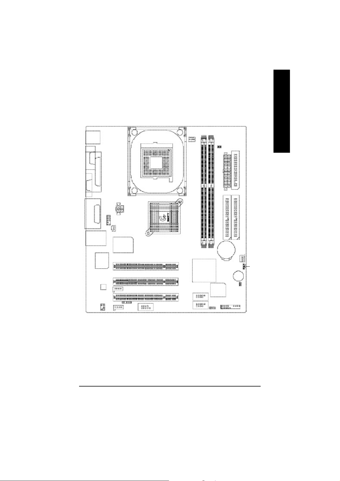
GA-8VD667K Motherboard Layout
KB_MS
COMA
CPU_FAN
DDR1
English
DDR2
DIMM _LED
FDD
VGA
LINE_OUTMIC_IN
LINE_IN
USB/
Intel 8 2562ET
LPTGAME
LAN
AC 97
SUR_CEN
F_AUDIO
ATX_12 V
SPDIF
ITE 871 2
IR
AUX_IN
CD _IN
SOC KET478
GA-8VD667K
COM B
Intel 8 45GV
PCI1
PCI2
PCI3
F_U SB2
F_U SB1
IC H4
BIOS
PWR_L ED
ATX_POWER
IDE2
BAT1
Buzzer
CI
F_PANEL
IDE1
SYS _FAN
CLR_COMS
- 7 -
Introduction
Page 12
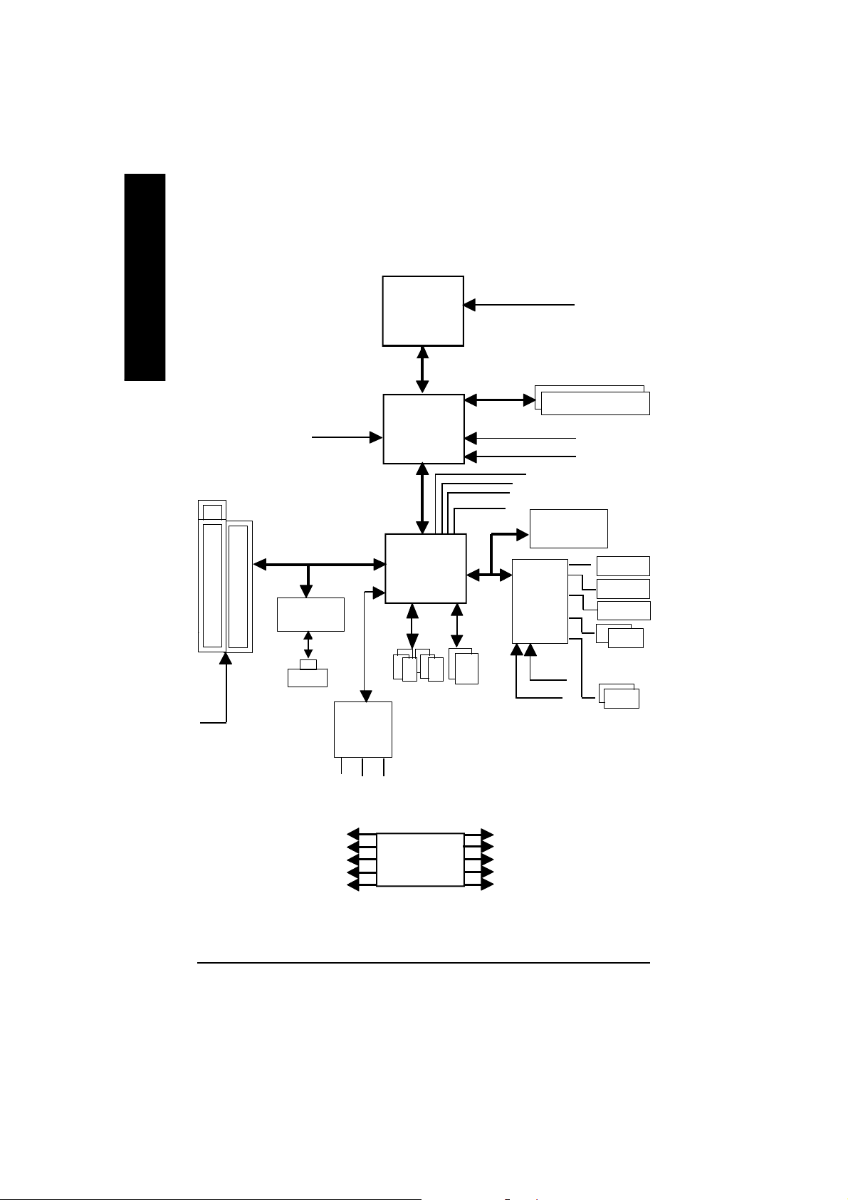
Block Diagram
English
PCICL K
(33MHz)
3 P CI
AGPC LK
(66MHz)
Intel 82562ET
RJ45
AC97
CODE C
Pentium 4
CP U
82845GV
AC97 Link
6 U SB
Ports
(2.0/1.1)
CPUCLK+/- ( 100/133MHz)
System B us 400/533 MHz
266/200 MHz
Intel
Intel
ICH 4
MCHCLK+/- (100/133MHz)
GMCHCLK (66M Hz)
48 MHz
LPC BUS
ATA33/66/100
IDE Channels
66 MHz
33 MHz
14.318 MHz
ITE8712
24 MHz
33 MHz
DDR RAM
FWH
Game Port
Flop py
LPT Port
PS/2
KB/M ouse
COM
Por ts
PCICLK (33M Hz)
USBCLK (48 MHz)
14.318 MHz
33 MHz
24 MHz
MIC
LINE-IN
LINE-OUT
CLK
GEN
- 8 -GA-8VD667K Motherboard
MCHCLK+/- (100/133M Hz)
CPUCLK+/- ( 100/133MHz)
AGPCLK (66M Hz)
GMCHCLK (66M Hz)
ICH3V66 (66MHz)
Page 13
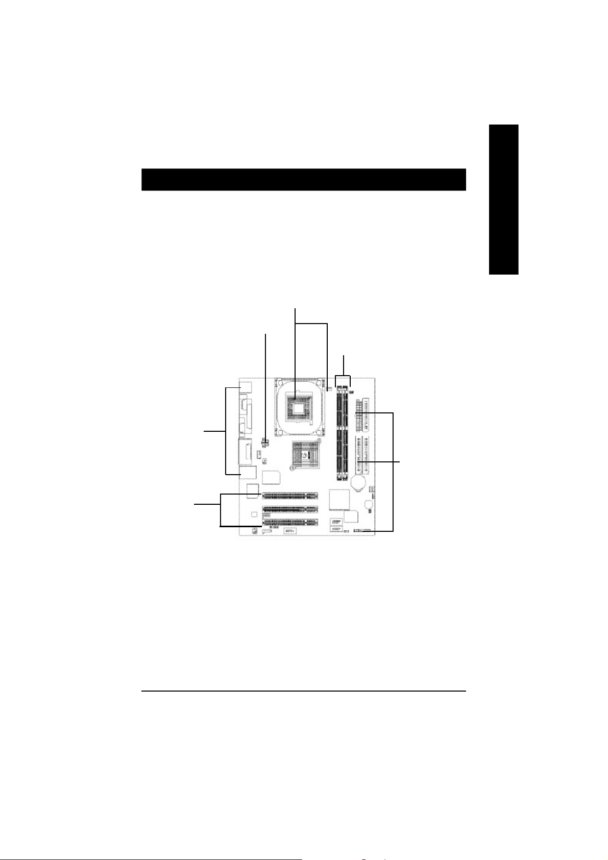
Chapter 2 Hardware Installation Process
To set up your computer, you must complete the following steps:
Step 1- Install the Central Processing Unit (CPU)
Step 2- Install memory modules
Step 3- Install expansion cards
Step 4- Connect ribbon cables, cabinet wires, and power supply
Step1
Step4
Step 2
Step 4
English
Step 4
Step3
Congratulations you have accomplished the hardware installation!
Turn on the power supply or connect the power cable to the power outlet. Continue with
the BIOS/software installation.
- 9 - Hardware Installation Proc ess
Page 14
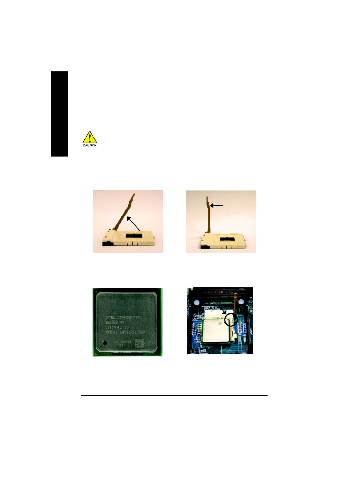
Step 1: Install the Central Processing Unit (CPU)
English
Step 1-1: CPU Installation
Before installing the processor , adhere to the following warning:
If you do not match the CPU socket Pin 1 and CPU cut edge well, it will
cause improper installation. Please change the insert orientation.
Please make sure the CPU type is supported by the motherboard.
Angling the
rod to 65
1. Angling the rod to 65-degree maybe feel a
kind of tight , and then continue pull the rod to
90-degree when a noise “cough” made.
0
Pin1 indicator
3. CPU Top V iew
Socket
Actuation
Lever
2. Pull the rod to the 90-degree directly.
Pin1 indicator
4. Locate Pin 1 in the socket and look
for a (golden) cut edge on the CPU
upper corner. Then insert the CPU
into the socket.
- 10 -GA-8VD667K Motherboard
Page 15

Step 1-2 : CPU Heat Sink Installation
Before installing the CPU Heat Sink , adhere to the following warning:
1.Please use Intel approved cooling fan.
2.We recommend you to apply the thermal tape to provide better heat conduction
between your CPU and heatsink.
(The CPU cooling fan might stick to the CPU due to the hardening of the thermal
paste. During this condition if you try to remove the cooling fan, you might pull the
processor out of the CPU socket alone with the cooling fan, and might damage the
processor. To avoid this from happening, we suggest you to either use thermal tape
instead of thermal paste, or remove the cooling fan with extreme caution.)
3.Make sure the CPU fan power cable is plugged in to the CPU fan connector, this
completes the installation.
Please refer to CPU heat sink user's manual for more detail installation procedure.
English
1. Fasten the heatsink supporting-base
onto the CPU socket on the
mainboard.
2. Make sure the CPU fan is plugged to
the CPU fan connector, than install
complete.
- 11 - Hardware Installation Proc ess
Page 16
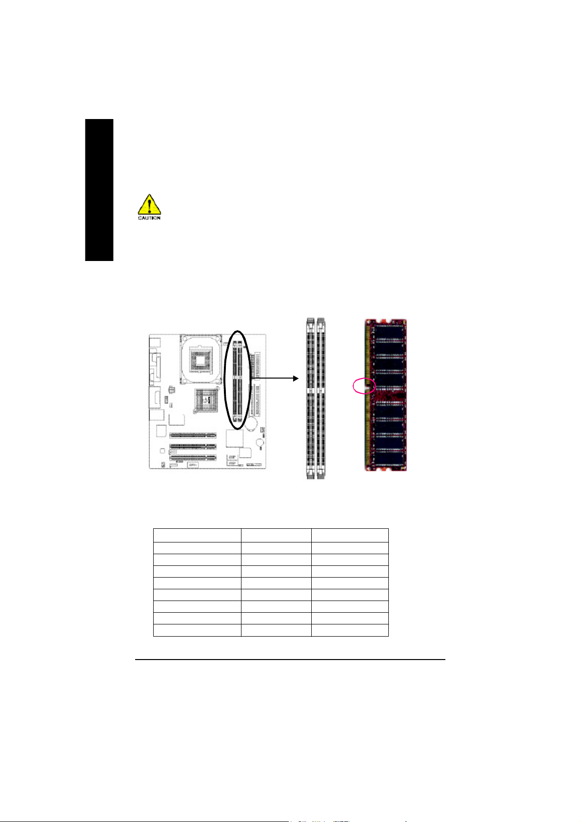
Step 2: Install memory modules
English
The motherboard has 2 dual inline memory module (DIMM) sockets. The BIOS will automatically detects
memory type and size. To install the memory module, just push it vertically into the DIMM socket .The
DIMM module can only fit in one direction due to the notch. Memory size can vary between sockets.
Before installing the processor and heatsink, adhere to the following warning:
When DIMM LED is ON, do not install/remove DIMM from socket.
Please note that the DIMM module can only fit in one direction due to the one notches.
Wrong orientation will cause improper installation. Please change the insert orientation.
Notch
Total Memory Sizes With Unbuffered DDR DIMM
Devices us ed on DIMM 1 DIMM x 64 2 DIMM s x 64
64 M bit (2M x8x4 banks) 128 M Bytes 256 M Bytes
64 M bit (1M x16x4 banks) 32 MBytes 64 MBytes
128 Mbit(4Mx8 x4 banks) 256 M Bytes 512 M Bytes
128 Mbit(2Mx16 x4 banks) 64 MBytes 128 M Bytes
256 Mbit(8Mx8 x4 banks) 512 M Bytes 1 GBytes
256 Mbit(4Mx16 x4 banks) 12 8 M Bytes 256 M Bytes
512 Mbit(16Mx8 x4 banks) 1 GBytes 2 GBytes
512 Mbit(8Mx16 x4 banks) 25 6 M Bytes 512 M Bytes
- 12 -GA-8VD667K Motherboard
DDR
Page 17

1. The DIMM slot has a notch, so the DIMM
mem ory modu le can only fit in one direction.
2. Insert the DIMM memory module vertically into
the DIMM slot. Then push it down.
3. Close the plastic clip at both edges of the DIMM
slots to lock the DIMM m odule.
Rever se the in stallation steps when you wish
to remove the DIMM module.
DDR Introduction
Established on the existing SDRAM industry infrastructure, DDR (Double Data Rate) memory is a high
performance and cost-effective solution that allows easy adoption for memory vendors, OEMs and
system integrators.
DDR memory is a sensible evolutionary solution for the PC industry that builds on the existing SDRAM
infrastructure, yet makes awesome advances in solving the system performance bottleneck by doubling
the memory bandwidth. DDR SDRAM will offer a superior solution and migration path from existing
SDRAM designs due to its availability, pricing and overall market support. PC2100 DDR memory
(DDR266) doubles the data rate through reading and writing at both the rising and falling edge of the clock,
achieving data bandwidth 2X greater than PC133 when running with the same DRAM clock frequency.
With peak bandwidth of 2.664GB per second, DDR memory enables system OEMs to build high
performance and low latency DRAM subsystems that are suitable for servers, workstations, high-end
PC's and value desktop SMA systems. With a core voltage of only 2.5 Volts compared to conventional
SDRAM's 3.3 volts, DDR memory is a compelling solution for small form factor desktops and notebook
applications.
English
- 13 - Hardware Installation Proc ess
Page 18
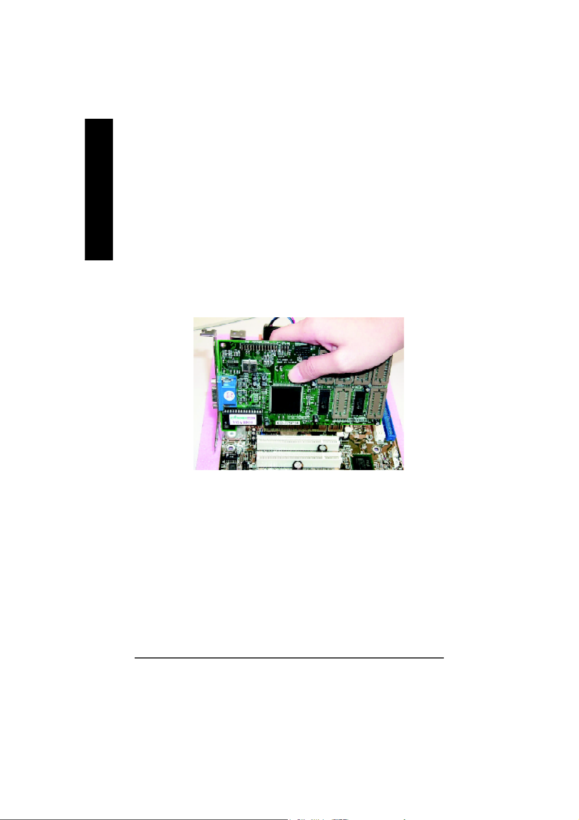
Step 3: Install expansion cards
1. Read the related expansion card’s instruction document before install the expansion card into
English
2. Remove your computer’s chassis cover, screws and slot bracket from the computer.
3. Press the expansion card firmly into expansion slot in motherboard.
4. Be sure the metal contacts on the card are indeed seated in the slot.
5. Replace the screw to secure the slot bracket of the expansion card.
6. Replace your computer’s chassis cover.
7. Power on the computer, if necessary, setup BIOS utility of expansion card from BIOS.
8. Install related driver from the operating system
the computer.
- 14 -GA-8VD667K Motherboard
Page 19
Step 4: Connect ribbon cables, cabinet wires, and power
supply
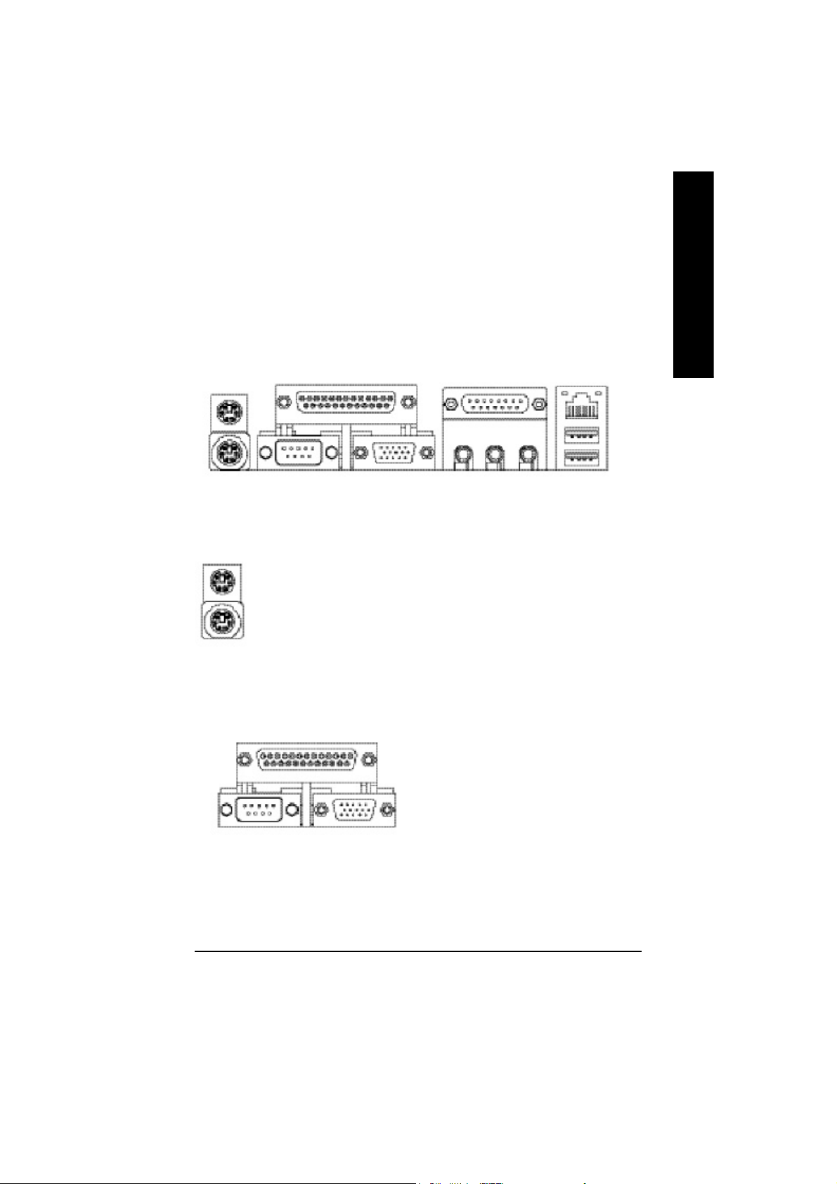
Step4-1 : I/O Back Panel Introduction
English
u
v w
x
u PS/2 Keyboard and PS/2 Mouse Connector
PS/2 Mouse Connector
(6 pin Female)
PS/2 Keyboard Connector
(6 pin Female)
ØThis connector supports standard PS/2
keyboard and PS/2 mouse.
v Parallel Port ,VGA port and Serial Ports (COMA)
Parallel Port
(25 pin Female)
Ø This mainboard supports 1 standard COM port,
1 VGA port and 1 LPT port. Device like printer
can be connected to LPT port ; mouse and
modem etc can be connected to COM port.
y
COMA VGA
Serial Port
(9 pin Male)
VGA Port
(15 pin Female)
- 15 - Hardware Installation Proc ess
Page 20
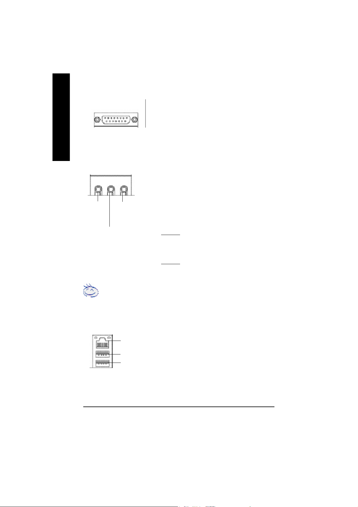
w Game /MIDI Ports
English
Joystick/ MIDI (15 pin Female)
ØThis connector supports joystick, MIDI keyboard and other
relate audio devices.
y Audio Connectors
Line Out
(Front
Speaker)
MIC In
(Center and Subwoofer)
Line In
(Rear Speaker)
Ø After install onboard audio driver, you may connect
speaker to Line Out jack, micro phone to MIC In jack.
Device like CD-ROM , walkman etc can be connected
to Line-In jack.
Please note:
You are able to use 2-/4-/6- channel audio feature by
S/W selection.
If you want to enable 6-channel function, you have 2
choose for hardware connection.
Method1:
Connect “Front Speaker” to “Line Out”
Connect “Rear Speaker” to “Line In”
Connect “Center and Subwooferr” to “MIC Out “.
Method2:
You can refer to page 23, and contact your nearest dealer
for optional SUR_CEN cable.
If you want the detail information for 2-/4-/6-channel audio setup
installation, please refer to “2-/4-/6-Channel Audio Function Introduction”.
y USB/ LAN Connector
LAN
USB 0
USB 1
Ø Before you connect your device(s) into USB
connector(s), please make sure your device(s) such as
USB keyboard, mouse, scanner, zip, speaker..etc. Have
a standard USB interface. Also make sure your OS
supports USB controller. If your OS does not support
US Bcontroller, please contact OS vendor for possible
patch or driver upgrade. For more information please
contact your OS or device(s) vendors.
- 16 -GA-8VD667K Motherboard
Page 21
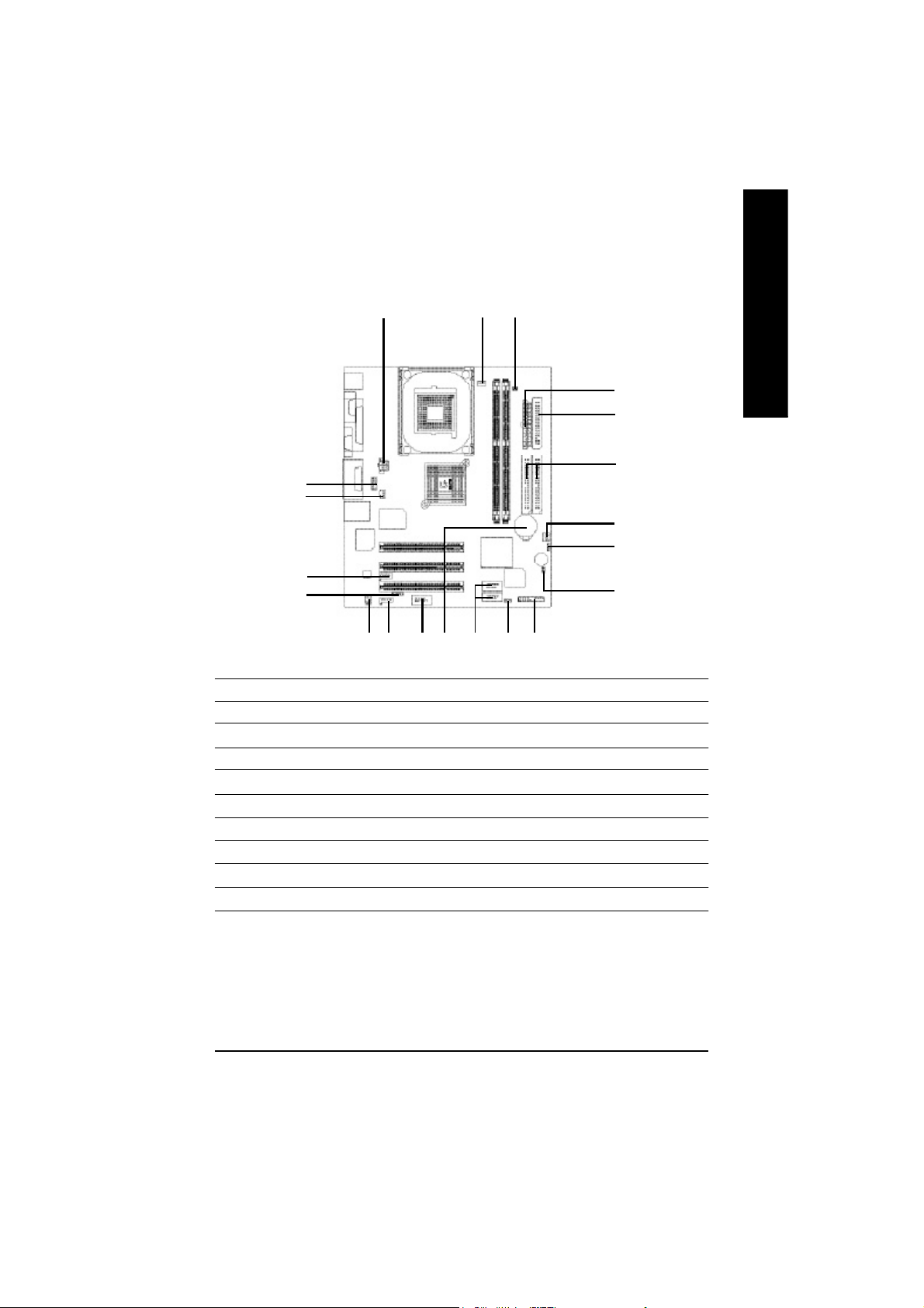
Step 4-2 : Connectors Introduction
English
11
13
15
18
1) ATX_12V
2) ATX
3) CPU_FAN
4) SYS_FAN
5) FDD
6) IDE1/IDE2
7) BATTERY
8) PWR_LED
9) DIMM_LED
10) F_PANEL
1 3
12
9
717 16
814
11) F_AUDIO
12) SUR_CEN
13) SPDIF
14) CD_IN
15) AUX_IN
16) F_USB1/F_USB2
17) COMB
18) IR
19) CLR_CMOS
20) CI
2
5
6
4
19
20
10
- 17 - Hardware Installation Proc ess
Page 22
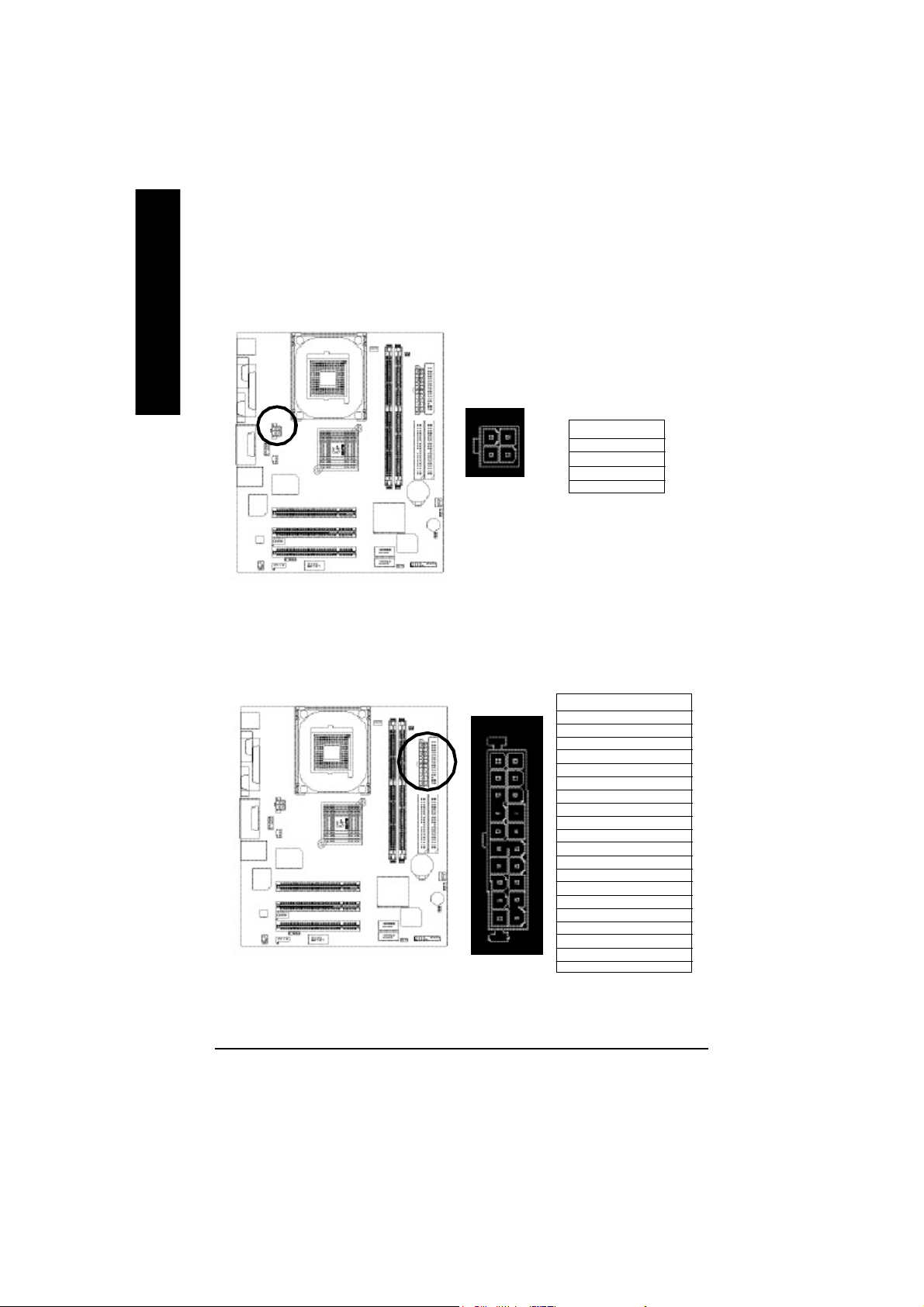
1) ATX_12V ( +12V Power Connector)
English
This conne ctor (ATX _12V) suppliesthe CPU operation voltage (Vcore). If this " ATX_ 12V
connector" is not connected, system cannot boot.
4
321
Pin No. Definition
1 GND
2 GND
3 +12V
4 +12V
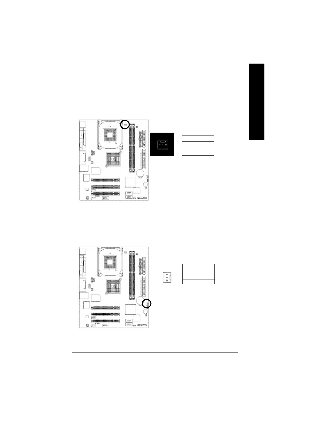
2) ATX_POWER (ATX Power)
AC power cord should only be connected to you r power supply unit after ATX power cable and
other related devices are firmly connected to the mainb oard.
Pin No. Definition
1 3.3V
2 3.3V
3 GND
11
20
4 VCC
1
5 GND
6 VCC
7 GND
8 Power Good
9 5V S B(stand by +5 V)
10 +12V
11 3.3V
12 -12V
13 GND
14 PS_ ON (softOn/O ff)
15 GND
16 GND
10
17 GND
18 -5V
19 VCC
20 VCC
- 18 -GA-8VD667K Motherboard
Page 23
3) CPU_FAN (CPU FAN Connector)
Please note, a proper installation of the CPU cooler is essential to prevent the CPU from running
under abnorm al condition or da maged by overheating.The C PU fan connector supports Max.
current up to 600 mA.
Pin No. Definition
1
1 GND
2 +12V
3 Sense
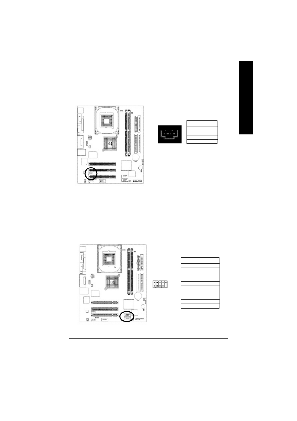
4) SYS_FAN (System FAN Connector)
This c onnector a llows you to li nk with the cooling fan on the system case to lower the system
temperature.
English
Pin No. Definition
1 GND
2 +12V
1
3 Sense
- 19 - Hardware Installation Proc ess
Page 24
5) FDD (Floppy Connector)
English
Please conne ct the floppy drive ri bbon cables to FDD. It supports 360K, 720K,1.2M,1.44M and
2.88M bytes floppy disk types. The red stripe of the ribbon cable m ust be the same side with the
Pin1.
34
2
33
1
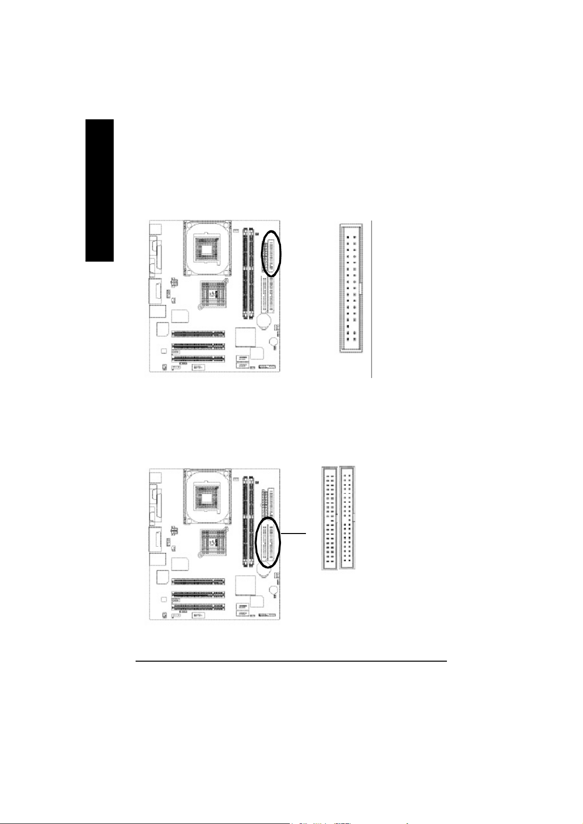
6) IDE1/ IDE2(IDE1/IDE2 Connector)
Please connec t first harddisk to IDE1 and connect CDROM to IDE2. The red stripe of the ribbon
cable m ust be the sam e side with the Pin1.
40
39
IDE2
1
IDE1
2
- 20 -GA-8VD667K Motherboard
Page 25
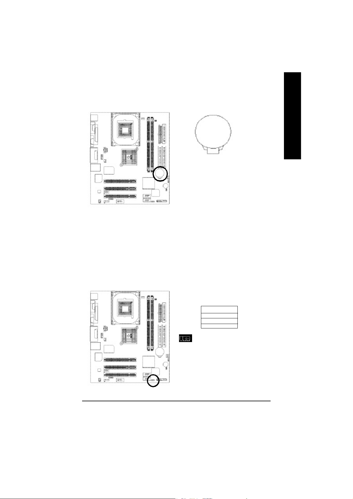
7) BATTERY (Battery)
+
CAUTION
v Danger of explosion if battery is incorrectly
replaced.
v Replace only with the same or equivalent
type recommended by the manufacturer.
v Dispose of used batteries according to the
If you want to erase CMOS...
1.Turn OFF the computer and unplug the power cord.
2.Remove the battery, wait for 30 second.
3.Re-install the battery.
4.Plug the power cord and turn ON the computer.
8) PWR_LED
PWR_LE D is con nect with the system power indicator to indicate whether the system is on/o ff. It
will blink when the sy stem enters sus pend m ode. If you use dual colo r LED, p ower LED will turn
to another color.
manufacturer’s instructions.
English
Pin No. Definition
1 MPD+
2 MPD3 MPD-
1
- 21 - Hardware Installation Proc ess
Page 26

9) DIMM_LED
English
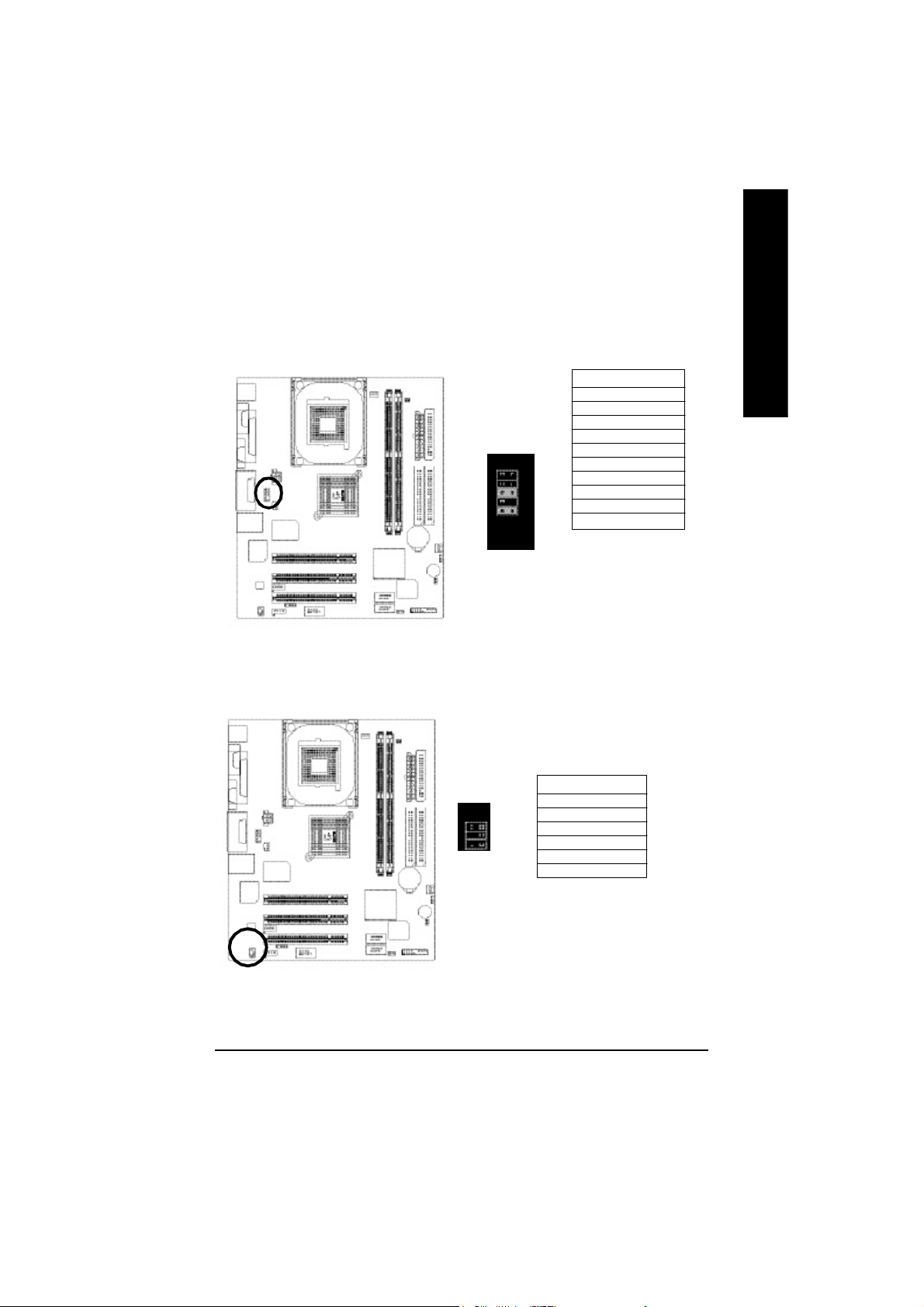
10) F_PANEL (2x10 pins connector)
Do not remov e mem ory modules while DIMM LED is on. It might cause short or other
unexpec ted damages due to the 2.5 V stand by vo ltage. Remove mem ory modu les only when AC
Power cord is dis connected.
+ -
Please connect the power LED, PC peaker, reset switch an d power switch etc of your
chassis front panel to the F_PANEL connector acc ording to the pin assignm ent above.
Mes sa ge LE D/ Po we r/
Sleep L ED
MPD -
MPD +
IDE H ard Disk
Acti ve LED
HD+
HD-
Soft P ower
Connec tor
PW+
1
1
1
RS E-
Reset S witch
1
RSE +
PW-
Speaker
Connector
SP K -
SP K+
202
1
1
NC
19
HD (IDE Hard Di sk Active LED) Pin 1: LED anode(+) Pin 2: LED cathode(-)
SPK (Speaker Connector) Pin 1: VCC(+) Pin 2- Pin 3: NC
Pin 4: Data(-)
RSE (Reset Switch) Open: Normal Operation
Close: Reset Har dware System
PW (Soft Power Co nnector) Open: Normal Operation Close : Power O n/Off
MPD( Message LED/Power/Sleep LED) Pin 1: LED anode(+)
Pin 2: LED cathode(-)
N C N C
- 22 -GA-8VD667K Motherboard
Page 27
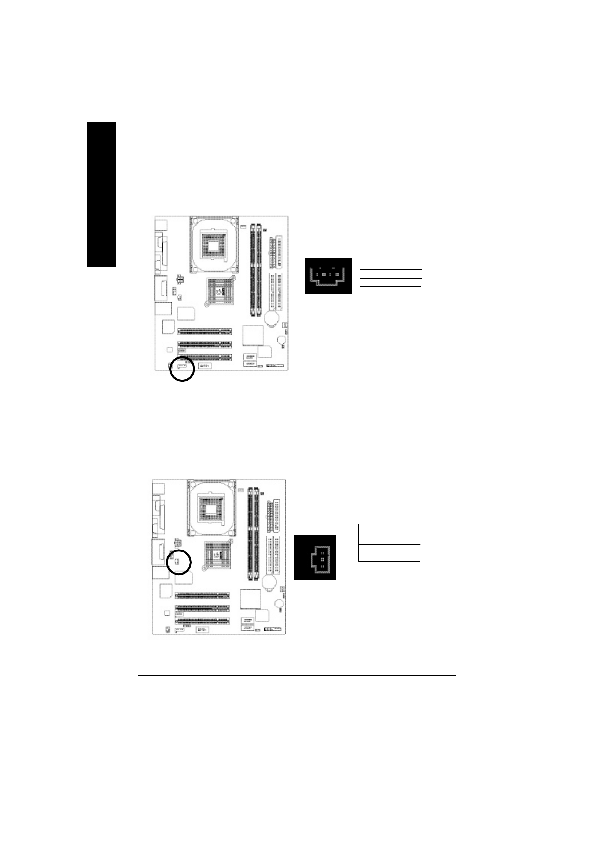
11) F_AUDIO (F_AUDIO Connector)
If you want to use Fron t Audio connector, you m ust remove 5-6, 9-10 Jumper. In order to utilize the
front audio header, your chassis m ust have front audio connector. Also pleas e make s ure the pin
assigment on the cable is the sam e as the pin assigment on the MB head er. To find out if the chassis
you are buying support front audio conne ctor, please contact y our dealer.
Pin No. Definition
1 MIC
2 GND
3 REF
4 POWER
5 FrontAudio(R)
1
2
10
9
6 RearAudio(R)
7 Reserved
8 No Pin
9 FrontAudio (L)
10 RearAudio(L)
12) SUR_CEN
Please co ntact your nearest dealer for optional SUR_CEN cable.
English
Pin No. Definition
1 SUR OUTL
2 SUR OUTR
625
1
3 GND
4 No Pin
5 CENTER_OUT
6 BASS_OUT
- 23 - Hardware Installation Proc ess
Page 28
13) CD_IN (CD IN,Blank)
English
14) SPDIF_O (SPDIFOut)
Connect CD-ROM o r DVD-ROM audio out to the connector.
Pin No. Definition
1
The SPDIF output is capab le of providing digital audio to external speakers or com pressed AC3
data to an e xternal Dolby D igital Decoder. Use this feature only when your stereo system has
digital input function.
1 CD-L
2 GND
3 GND
4 CD_R
Pin No. Definition
1 VCC
1
- 24 -GA-8VD667K Motherboard
2 SPDIF OUT
3 GND
Page 29
15) AUX_IN ( AUX In Connector)
Connect other devi ce(such as PCI TV Tu nner audio out)to the connector.
English
1
Pin No. Definition
1 AUX-L
2 GND
3 GND
4 AUX_R
16) F_ USB1 / F_USB2(Front USB Connector, Yellow )
Be careful with the polarity of the front USB co nnector. Check the pin assignment while you
connect the front USB cable. Please con tact your nearest dealer for optional front USB
cable.
Pin No. Definition
1 Power
2
10
1
9
2 Power
3 USB DX4 USB Dy5 USB DX+
6 USB Dy+
7 GND
8 GND
9 No Pin
10 U SB Over Current
- 25 - Hardware Installation Proc ess
Page 30

17) COM B(COM B Connector)
English
18) IR_CIR
Be careful with the polarity of the COMB connector. Check the pin assignment while you
connect the COMB cable.Please contact your nearest dealer for optional COMB cable.
Pin No. Definition
10
2
1
9
1 NDCDB2 NSINB
3 NSOUTB
4 NDTRB5 GND
6 NDSTRB7 NRTSB8 NCTSB9 NRIB
10 N C
Be careful with the polarity of the IR connectorwhile you connect the IR. Please contact you nearest
dealer for optional IR device.
Pin No. Definition
1 VCC(+5V)
1
- 26 -GA-8VD667K Motherboard
5
2 NC
3 IR Data Input
4 GND
5 IR DAta Output
Page 31

19) CLR_CMOS (Clear CMOS)
You may cle ar the CMOS d ata to its default values by this jumper. Default doesn’t include the "Shunter"
to prevent from impro per use this jumper. To clear CMO S, temporarily s hort 1-2 pin.
2-3 close: Normal
1
1-2 close: Clear CMOS
1
20) CI (CASE OPEN)
This 2 pin connector allows your system to enable or disable the "ca se open" item in BIOS
if the system case b egin remo ve.
English
Pin No. Definition
1 Signal
1
- 27 - Hardware Installation Proc ess
2 GND
Page 32

English
- 28 -GA-8VD667K Motherboard
Page 33

Chapter 3 BIOS Setup
BIOS Setup is an overview of the BIOS Setup Program. The program that allows users to modify the
basic system configuration. This type of information is stored in battery-backed CMOS RAM so that it
retains the Setup information when the power is turned off.
English
ENTERING
Powering ON the computer and pressing <Del> immediately will allow you to enter Setup. If you require
more advanced BIOS settings, please go to “advanced BIOS” setting menu.To enter Advanced BIOS
setting menu, press “Ctrl+F1” key on the BIOS screen.
CONTROL
<á> Move to previous item
<â> Move to next item
<ß> Move to the item in the left hand
<à> Move to the item in the right hand
<Esc> Main Menu - Quit and not save changes into CMOS Status Page Setup Menu and
<+/PgUp> Increase the numeric value or make changes
<-/PgDn> Decrease the numeric value or make changes
<F1> General help, only for Status Page Setup Menu and Option Page Setup Menu
<F2> Itemhelp
<F3> Reserved
<F4> Reserved
<F5> Restore the previous CMOS value from CMOS, only for Option Page Setup Menu
<F6> Load the file-safe default CMOS value from BIOS default table
<F7> Load the Optimized Defaults
<F8> Q-Flash function
<F9> Reserved
<F10> Save all the CMOS changes, only for Main Menu
SETUP
KEYS
Option Page Setup Menu - Exit current page and return to Main Menu
- 29 - BIOS Setup
Page 34

GETTING HELP
The on-line description of the highlighted setup function is displayed at the bottom of the screen.
English
Press F1 to pop up a small help window that describes the appropriate keys to use and the possible
selections for the highlighted item. To exit the Help Window press <Esc>.
The Main Menu (For example: BIOS Ver. : F1)
Once you enter Award BIOS CMOS Setup Utility, the Main Menu (Figure 1) will appear on the screen.
The Main Menu allows you to select from eight setup functions and two exit choices. Use arrow keys to
select among the items and press <Enter> to accept or enter the sub-menu.
Main Menu
Status Page Setup Menu / Option Page Setup Menu
CMO S Setup Utility-Copyr ight (C) 1984 -2002 Award S oftware
}Standard CMOS Fe atures Top Performance
}Advanced BIOS Features Load Fail-Safe Defaults
}Integrated Peripherals Load Optimiz ed Defaults
}Power Manag ement Setup Se t Superviso r Pas sword
}PnP/PCI Configurations Set Us er Pa ssword
}PC Health Status Save & Exi t Setup
}Frequency/ Voltage Control Exit Without Saving
ESC:Qu it higf:Select Item
F8: Q-Fl ash F10:Sa ve & E xit Setup
Tim e, Date, Har d Disk T ype...
Figure 1: Main M enu
If you can’t find the setting you want, please press ”Ctrl+F1” to
search the advanced option widden.
l Standard CMOS Features
This setup page includes all the items in standard compatible BIOS.
l Advanced BI OS Features
This setup page includes all the items of Award special enhanced features.
- 30 -GA-8VD667K Motherboard
Page 35

l Integrated Peripherals
This setup page includes all onboard peripherals.
l Power Management Setup
This setup page includes all the items of Green function features.
l PnP/PCI Configurations
This setup page includes all the configurations of PCI & PnP ISA resources.
l PC Health Status
This setup page is the System auto detect Temperature, voltage, fan, speed.
l Fr equency/Voltage Contr ol
This setup page is control CPU’s clock and frequency ratio.
l Top Performance
Top Performance Defaults indicates the value of the system parameters which the system
would be in best performance configuration.
l Load Fail-Safe Defaults
Fail-Safe Defaults indicates the value of the system parameters which the system would
be in safe configuration.
l Load Optimized Defaults
Optimized Defaults indicates the value of the system parameters which the system would
be in best performance configuration.
l Set Supervisor password
Change, set, or disable password. It allows you to limit access to the system and Setup,
or just to Setup.
l Set User password
Change, set, or disable password. It allows you to limit access to the system.
l Save & Exit Setup
Save CMOS value settings to CMOS and exit setup.
l Exit Without Saving
Abandon all CMOS value changes and exit setup.
English
- 31 - BIOS Setup
Page 36

Standard CMOS Features
English
CMO S Setup Utility-Copyr ight (C) 1984 -2002 Award S oftware
Standard CMOS Fe atures
Date (m m:dd:y y) Thu, Feb 21 2002 Item Help
Time (hh:mm :ss) 22:31:24 Menu Level u
}IDE Prima ry Master [Press Enter No ne] C ha ng e th e da y , mon th,
}IDE Pri mary Slave [Press En ter None] ye ar
}IDE Secondary Master [Pr ess Enter None] < We ek>
}IDE Second ary Sla ve [Press Enter None] Su n. to Sa t.
Drive A [1.4 4M, 3.5”] <Month>
Drive B [Non e] Jan. to D ec.
Floppy 3 Mode Support [Disabled] <Day>
1 to 3 1(or max i mun a llow ed
Halt On [All, But Key board] i n the mo nth. )
Base M em ory 640K <y ea r>
Extended M em ory 130048K 19 9 9 to 20 9 8
Total Mem ory 131072K
higf: M ove Enter:S elect +/-/PU/ PD:Value F10:Sav e ESC:Exit F1:General H elp
F3:Language F5:Pre vious Values F6:Fai l-Safe Defaults F7:Optimized Defaults
Figure 2: Standard CM OS Features
C Date
The date format is <week>, <month>, <day>, <year>.
8Week The week, from Sun to Sat, determined by the BIOS and is display only
8Month The month, Jan. Throu gh Dec.
8Da y The day, from 1 to 31 (or the maxim um allowed in the month)
8Year The year, from 1999 through 2098
C Time
The times format in <hour> <minute> <second>. The time is calculated base on the 24-hour military-
time clock. For example, 1 p.m. is 13:00:00.
- 32 -GA-8VD667K Motherboard
Page 37

C IDE Primary Master, Slave / IDE Secondar y Master, Slave
The category identifies the types of hard disk from drive C to F that has been installed in the computer.
There are two types: auto type, and manual type. Manual type is user-definable; Auto type which will
automatically detect HDD type.
Note that the specifications of your drive must match with the drive table. The hard disk will not work
properly if you enter improper information for this category.
If you select User Type, related information will be asked to enter to the following items. Enter the
information directly from the keyboard and press <Enter>. Such information should be provided in the
documentation form your hard disk vendor or the system manufacturer.
8Capac ity: The hard disk size. The unit is Mega Bytes.
8Access M ode: The options are: Auto / Large / LBA / Norm al.
8Cylinde r: The cylinder number of hard disk.
8Head The read / Write head number of hard disk.
8Precomp The cyliner num ber at which the disk driver changes the write current.
8Landing Zone The cylinder number that the disk driver heads(read/write) are seated when the
disk drive is parked.
8SECTO RS The sector number of each track define on the hard disk.
If a hard disk has not been installed select NONE and press <Enter>.
C Drive A / Drive B
The category identifies the types of floppy disk drive A or drive B that has been installed in the
computer.
8None No floppy drive installed
8360K, 5.25 ". 5.25 i nch PC-type standard d rive; 360K byte capacity.
81.2M , 5.25 ". 5. 25 inch AT-type high- density drive; 1.2M byte capaci ty
(3.5 inch when 3 Mode is Enabled).
8720K, 3.5 ". 3.5 inc h double-s ided drive; 7 20K byte capacity
81.44M , 3.5 ". 3.5 inch do uble-sided dri ve; 1.44M byte capacity.
82.88M , 3.5 ". 3.5 inch do uble-sided dri ve; 2.88M byte capacity.
English
C Floppy 3 Mode Support (for Japan Area)
8Disabled Norm al Floppy Driv e. (Default value)
8Drive A Drive A is 3 m ode Floppy Driv e.
8Drive B Drive B is 3 m ode Floppy Driv e.
8Both Drive A & B are 3 mod e Floppy Drives.
- 33 - BIOS Setup
Page 38

CHalt on
English
C Memory
The category determines whether the computer will stop if an error is detected during power up.
8NO Erro rs The system bo ot will not stop for any erro r that may be detected
and you will be p rompted.
8All Err ors Whenever the BIOS detects a non-fatal error the system will be stopped.
8All, Bu t Keyboard The sys tem boot will not stop for a keyb oard error; it will s top for
all other errors. (Default value)
8All, But Diskette The system boot will not stop for a disk error; it will s top for all
other errors.
8All, But Di sk/Key The sy stem boo t will not stop for a keyboard or d isk error; it will
stop for all other errors.
The category is display-only which is determined by POST (Power On Self Test) of the BIOS.
Base Memory
The POST of the BIOS will determine the amount of base (or conventional)
memoryinstalled in the system.
The value of the base memory is typically 512 K for systems with 512 K
memoryinstalled on the motherboard, or 640 K for systems with 640 K or
more memory installed on the motherboard.
Extended Memory
The BIOS determines how much extended memory is present during the
POST.
This is the amount of memory located above 1 MB in the CPU’s memory
address map.
- 34 -GA-8VD667K Motherboard
Page 39

Advanced BIOS Features
CMO S Setup Utility-Copyr ight (C) 1984 -2002 Award S oftware
Advanced BIOS Features
First Boot Device Flop py Item Help
Second Bo ot Device HDD-0 M enu Level u
Third Boo t Device CDROM
Boot Up Floppy Se ek Disabled
Pas sword Check Setup
#CPU Hyper -Threading Enabled
Init Display First Onboard/AGP
Graphics Aperture Size 128MB
Graphics Share M emory 8MB
higf: M ove Enter:Select + /-/PU/PD:Value F10:Save ESC:Exit F1:Gener al Help
F5:Previous Values F6:Fai l-Safe Defaults F7:Optimized Defaults
Figure 3 : Advanced BIOS Features
English
“ # ” System will detect automatically and show up when you install the Intel
Pentium® 4 processor with HT Technology.
C First / Second / Third Boot Device
8Flo ppy Selec t your boo t device p riority by Floppy.
8LS120 Select your boot device priority by LS120.
8HDD-0~3 Select your boot device priority by HDD-0~3.
8SCS I Selec t your bo ot device priority by SCSI.
8CDROM Se lect your boot device priority by CDROM .
8ZIP Selec t your boo t device p riority by ZIP.
8USB-FDD Select your bo ot device pr iority by US B-FDD.
8USB-Z IP Select your boot device priority by USB-ZIP.
8USB-CDR OM Select your boot device priori ty by USB-CDROM.
8USB-HDD Select your boot device priority by USB-HDD.
8LAN Select your boot devic e prio rity by LAN.
8Disabled Sel ect your boo t device pri ority by Dis abled.
- 35 - BIOS Setup
®
Page 40

C Boot Up Floppy Seek
English
C Passwor d Check
CCPU Hyper-Threading
During POST, BIOS will determine the floppy disk drive installed is 40 or 80 tracks. 360 K type is
40 tracks 720 K, 1.2 M and 1.44 M are all 80 tracks.
8Enabled BIOS searches for floppy disk drive to determine it is 40 or 80 tracks. N ote
that BIOS can not tell from 720 K, 1.2 M o r 1.44 M dr ive type as they are
all 80track s.
8Disabled BIOS will no t search for the type of floppy disk drive by track number. N ote
that there will not be any warning m essage if the driv e installed is 360 K.
(Default value)
This category allows you to limit access to the system and Setup, or just to Setup.
8Sys tem The user must enter correct password in order to access the system an d/or
BIOS setup.
8Setup The user must enter correct password in order to access BIOS setup utility.
(Default value)
8Enabled Enables CPU Hyper Threading Feature. Plea se note that this feature is only
working for op erating system with mu lti processors m ode supported.
(Default value)
8Disabled Disables CPU Hyper T hreading.
CInit Display First
8Onboard AGP Set Init Display First to onboard/AGP. (Default value)
8PC I Set Init Disp lay First to PC I.
CGraphics Aperture Size
8128MB Set Graphics Aperture Size to 128MB. (D efault value)
8Disabled Disable this function.
CGraphics Share Memory
88MB Set Graphics Share M emory to 8MB. (Default value)
81MB Set Graphics Share Mem ory to 1MB.
- 36 -GA-8VD667K Motherboard
Page 41

Integrated Peripherals
CMO S Setup Utility-Copyr ight (C) 1984 -2002 Award S oftware
Integrated Peripherals
On-Chip P rimary PCI IDE Enabled Item Help
On-Chip Secondary PCI IDE Enabled Men u Level u
IDE1 Conductor Cable Auto If a hard disk
IDE2 Conductor Cable Auto controller card is
USB Controller Enabled used, set at Disable
USB Keyboa rd Support Disabled
USB M ouse Support Disabled [Enabled]
AC97 Au dio Auto Enable onboard IDE
Onboard H/W LAN Enabled POR T
Onboard LAN Boo t ROM Disabled
Onboard Serial Port 1 3F8/IRQ4
Onboard Serial Port 2 2F8/IRQ3
UART M ode Sel ect Normal
x UR2 Duplex Mode Half [Disabled]
Onboard Parallel Port 378/ IRQ7 Disable onboard IDE
Parallel Port Mode SP P PORT
x ECP Mod e Use D MA 3
Game Port Address 201
Midi Port Address 330
Midi Port IRQ 10
English
higf: M ove Enter:Select + /-/PU/PD:Value F10:Save ESC:Exit F1:Gener al Help
F5:Pre vious Values F6:Fail-Safe Defaults F7:Optim ized Defaults
Figure 4: Integrated Peripherals
- 37 - BIOS Setup
Page 42

C On-Chip Primary PCI IDE
MWhen enabled, allows you to use the onboard primary PCI IDE. If a hard disk controller card i s used,
set at Disabled.
English
C On-Chip Secondar y PCI IDE
MWh en enabled, allows you to use the on board second ary PCI IDE. If a hard disk controller card is
used, set a t Disabled.
C IDE1 Conductor Cable
C IDE2 Conductor Cable
8Enabled Enable onboard 1st channel IDE port. (Default value)
8Disabled Disable on board 1st channel IDE port.
8Enabled Enable onboard 2nd channel IDE port. (Default value)
8Disabled Disable onboard 2nd channel IDE port.
8Auto Will be automatically detected by BIOS. (Default Value)
8ATA66/100 Set IDE1 Conductor Cable to ATA66/100 (Please make sure your IDE device
and cable is com patible with ATA66/100).
8ATA33 Set IDE1 Conductor Cabl e to ATA33 (Please m ake sure your IDE device and
cable i s com patible with ATA33).
8Auto Will be automatically detected by BIOS. (Default Value)
8ATA66/100 Set IDE2 Conductor Cable to ATA66/100 (Please make sure your IDE device
and cable is com patible with ATA66/100).
8ATA33 Set IDE2 Conductor Cabl e to ATA33 (Please m ake sure your IDE device and
cable i s com patible with ATA33).
C USB Contr oller
MDisable this option if you are no t using the onboard USB feature.
8Enabled Enable USB Con troller. (Default value)
8Disabled Disa ble USB Controller.
C USB Keyboard Support
MWhen a USB keyboard is installed, please set at Enabled.
8Enabled Enable USB Keyboard Supp ort.
8Disabled Disa ble USB Keyboard Support. (Default value)
- 38 -GA-8VD667K Motherboard
Page 43

C USB Mouse Support
8Enabled Enable USB Mouse Support.
8Disabled Disabl e USB Mouse Support. (Default value)
C AC97 Audio
8Auto BIOS will automa tically detect onboard AC97 Au dio. (Default value)
8Disabled Disa ble this function.
C Onboard H/W LAN
8Enabled Enabled Onboard LAN function. (Default value)
8Disabled Disab led onboard LAN function.
C Onboard LAN Boot ROM
MThe function is to invoke onboard L AN chip to boot up the system
8Enabled Enabled Onboard LAN Boot ROM function.
8Disabled Disabl ed onboard LAN Boot ROM function.(Default value)
C Onboard Serial Port 1
8Auto BIOS will autom atically setup the por t 1 address.
83F8/IRQ4 Enable onboard Serial port 1 and address is 3F8. (Default value)
82F8/IRQ3 Enable onboard Serial port 1 and address i s 2F8.
83E8/IRQ4 Enable onboard Serial port 1 and address i s 3E8.
82E8/IRQ3 Enable onboard Serial port 1 and address i s 2E8.
8Disabled Disable onboard Serial port 1.
English
C Onboard Serial Port 2
8Auto BIOS will autom atically setup the por t 2 address.
83F8/IRQ4 Enable onboard Serial port 2 and address i s 3F8.
82F8/IRQ3 Enable onboard Serial port 2 and address is 2F8. (Default value)
83E8/IRQ4 Enable onboard Serial port 2 and address i s 3E8.
82E8/IRQ3 Enable onboard Serial port 2 and address i s 2E8.
8Disabled Disable onboard Serial port 2.
- 39 - BIOS Setup
Page 44

C UART Mode Select
MThis feature all ows you to determine which Infra Red(IR) function of Onboard I/O chip)
English
C UR2 Duplex Mode(When UART Mode Select is set [ASKIR or IrDA or SCR])
MThis feature a llows you to sele ct the IR modes.
C Onboard Parallel port
MThis feature allows you to select from a given set of parameters if the parallel p ort uses the onboard
I/O controller.
CParallel Port Mode
MThis feature allows you to con nect with an advanced p rint via the port m ode it supports.
8ASKIR Set onboard I/O chip UART to AS KIR Mode.
8IrDA Set onboard I/O chip UART to IrDA Mode.
8Normal Set onboard I/O chip UART to Norm al Mode. (Default Value)
8Half IR Function Duplex Half. (Default Value)
8Full IR Function Duple x Full.
8378/IRQ7 Enable onboard LPT port and address is 378/IRQ7. (Default Value)
8278/IRQ5 Enable onboard LPT port and address is 278/ IRQ5.
8Disabled Disable onboa rd LPT port.
83BC/ IRQ7 Enable onboard LPT port and address is 3BC/IRQ7.
8SPP Using Parallel port as Standard Parallel Port. (Default Value)
8EPP Using Parallel port as Enhanced Parallel Port.
8EC P Using Parallel port as Extended Ca pabilities Port.
8ECP+ EPP Usi ng Parallel port as ECP & E PP mode.
CECP Mode Use DMA(When Parall el Port Mode i s set [ECP or ECP+EPP])
83 Set ECP Mode Use DMA to 3. (D efault Value)
81 Set ECP M ode Use DM A to 1.
CGame Port Address
8201 Set Game Port Address to 201. (Default Value)
8209 Set Game Port Address to 209.
8Disabled Disa ble this function.
- 40 -GA-8VD667K Motherboard
Page 45

CMidi Port Address
English
CMidi Port IRQ
8300 Set Midi Port Address to 300.
8330 Set Midi Port Address to 330.(Default Value)
8Disabled Disa ble this function.
85 Set Midi Port IRQ to 5.
810 Set Midi Port IRQ to 10. (Default Value)
- 41 -GA-8VD667K Motherboard
Page 46

Power Management Setup
CMO S Setup Utility-Copyr ight (C) 1984 -2002 Award S oftware
Power Managem ent Setup
ACPI Susp end Ty pe S1(POS) Item Help
Power LED i n S1 State Blinking
Soft-Off by PWR _BTTN Instant-Off Men u Level u
PM E Event Wa ke Up Enabled [S1]
Modem RingOn Enabled
Resum e by Al arm Disabled Set sus pend type to
x Date (of Month) Alarm Ever yda y Power On Suspend u nder
x Tim e (hh:nn: ss) Alarm 0 0 0 ACPI OS
Power On By M ou se Disabled
Power On By Keyboa rd Disabled [S3]
x KB Power ON P assword Enter Set suspend type to
AC Bac k Function Soft-Off Suspend to RAM under
ACPI OS
higf: M ove Enter:Select + /-/PU/PD:Value F10:Save ESC:Exit F1:Gener al Help
F5 :Previous Values F6:Fail-Safe Defaults F7:Optim ized Defaults
Figure 5: Power Management Setup
English
C ACPI Suspend Type
This option will not be shown or not be available if you are using a CPU with the locked ratio.
8S1(POS) Set ACPI suspend type to S1. ( Default Value)
8S3(STR) Se t ACPI suspend type to S3.
C Power LED in S1 State
8Blinking In standby mode(S1), power LED will blink. (Default Value)
8Dual/Off In standby mode( S1):
a. If use si ngle colo r LED, power L ED will turn off.
b. If use dual color LED, power LED will turn to another col or.
- 42 - BIOS Setup
Page 47

C Soft-off by PWR_BTTN
English
C PME Event Wake Up
MWhen set at Enabled, any PCI-PM event awakes the system from a PCI-PM controlled state.
MThis feature requires an ATX power supply that provides at least 1A on the +5VSB
lead.
C ModemRingOn
MAn incom ing c all via mod em awakes the system from its soft-off mode.
C Resume by Alarm
8Instant-off Press power button then Power off instantly. (De fault value)
8Delay 4 Se c. Press power button 4 sec to Power off. Enter suspend if button is pressed less
than 4 s ec.
8Disabled Disa ble this function.
8Enabled Enable PM E Event Wake up. (Default Value)
8Disabled Disa ble this function.
8Enabled Enable Modem Ring on. (Default Value)
You can set "Resume by A larm" item to enabled and k ey in Data/time to power on system.
8Disabled Disable this function. (Default Value)
8Enabled Enable al arm function to POWER ON system.
If RTC Alarm Le ad To Power On i s Enabled.
Date ( of Mo nth) Alarm : Everyday , 1~ 31
Time ( hh: mm : ss) Ala rm : (0~23) : (0~59) : (0~59)
C Power On By Mouse
8Disabled Disab led this function. (Default value)
8Mo use Click Double cli ck on PS/2 m ouse left button.
- 43 -GA-8VD667K Motherboard
Page 48

C Power On By Keyboard
his feature allows you to set the method for powering-on the system.
The option “Password“ allows you to set up to 5 alphanumeric characters to power-on the system.
The option “Keyboard 98” allows you to use the standard keyboard 98 to power on the system.
8P assword Enter from 1 to 5 char acters to set the Keyboard P ower On Password.
8Disabled Disab led this function. (Default value)
8Keyboard 98 If your key board h ave “P OWER Key” button, you ca n press the key to
power on your system.
CKB Power ON Password
8Enter Input password (from 1 to 5 characters) and pres s Enter to set the Key
board Power On Password.
CAC Back Function
8Mem ory Sys tem power on d epends on the status before AC lost.
8Soft-Off Al ways in O ff state when AC b ack. (Default value)
8Full-On Al ways p ower on the s ystem when AC back.
English
- 44 - BIOS Setup
Page 49

PnP/PCI Configurations
English
PCI 1 IRQ As signm ent Auto Item Help
PCI 2 IRQ As signm ent Auto M enu Level u
PCI 3 IRQ As signm ent Auto
higf: M ove Enter:Select + /-/PU/PD:Value F10:Save ESC:Exit F1:Gener al Help
C PCI 1 IRQ Assignment
C PCI 2 IRQ Assignment
CMO S Setup Utility-Copyr ight (C) 1984 -2002 Award S oftware
PnP/PCI Configurations
F5 :Previous Values F6:Fail-Safe Defaults F7:Optim ized Defaults
Figure 6: PnP/PCI Configurations
8Auto Auto assign IRQ to PCI 1. (Default value)
83,4,5,7,9,10 ,11,12,14,15 Set IRQ 3,4,5,7 ,9,10,11,12,14,15 to PCI 1.
8Auto Auto assign IRQ to PCI 2. (Default value)
83,4,5,7,9,10 ,11,12,14,15 Set IRQ 3,4,5, 7,9,10,11,12,14,15 to PCI 2.
C PCI 3 IRQ Assignment
8Auto Auto assign IRQ to PCI 3. (Default value)
83,4,5,7,9,10 ,11,12,14,15 Set IRQ 3,4,5,7 ,9,10,11,12,14,15 to PCI 3.
- 45 -GA-8VD667K Motherboard
Page 50

PC Health Status
CMO S Setup Utility-Copyr ight (C) 1984 -2002 Award S oftware
PC Health Status
Reset Case Open Status Disabled Item Help
Case Opened No Menu Leve l u
VCO RE 1.744V
+1.5V 1.488V
+3.3V 3.312V
+5V 5.053V
+12V 11.840V
Current CPU Tempe rature 22°C
Current CPU FAN Spe ed 6490 RPM
Current SYSTEM FAN Sp eed 0 RPM
CPU Warning Tempe rature Disabled
CPU FAN Fail Warn ing Disabled
SYSTEM FAN Fail War ning Disabled
higf: M ove Enter:Select +/ -/PU/PD:Value F10:Save ESC:Exit F1:General H elp
F5:Previous Values F6:Fail-Safe Defaults F7: Optimized Defaults
Figure 7: PC Health Status
English
CReset Case Open Status
CCase Opened
If the c ase is clos ed, "C ase Opened" wil l sh ow "No".
If the case h ave b een open ed, "Cas e Opened" will s how "Yes".
If you want to reset " Case Ope ned" value, set "Reset Cas e Open Status" to
"Ena bled" an d sav e CMO S, your computer will r estart.
Disab led : Don’t reset case open status.;Enabled : Clear case open status at next boo t.
C Current Voltage (V) VCORE / 1.5V /+3.3V / +5V / +12V
8Detect system ’s voltage status automaticall y.
- 46 - BIOS Setup
Page 51

CCurrent CPU Temperature
8Detect CPU Tem p. automatically.
English
C Current CPU/SYSTEM FAN Speed (RPM)
C CPU War ning Temperature
C CPU FAN Fail Warning
C SYSTEM FAN Fail Warning
8Detect CPU/SYSTE M Fa n speed s tatus automatically.
860°C / 140°F M onitor CPU Temp. at 60°C / 140 °F.
870°C / 158°F M onitor CPU Temp. at 70°C / 158 °F.
880°C / 176°F M onitor CPU Temp. at 80°C / 176 °F.
890°C / 194°F M onitor CPU Temp. at 90°C / 194 °F.
8Disabled Don’t monitor current temperature.(Default value)
8Disabled Fan Warning Function Disable. (Default value)
8Enabled Fan Warning Function Enable.
8Disabled Fan Warning Function Disable. (Default value)
8Enabled Fan Warning Function Enable.
- 47 -GA-8VD667K Motherboard
Page 52

Frequency/Voltage Control
CMO S Setup Utility-Copyr ight (C) 1984 -2002 Award S oftware
Frequency/ Voltage Control
CPU Clock Ratio 15X Item Help
CPU Ho st Clock C ontrol Disabled Menu Level u
x CPU Host Freque ncy (M hz) 100
x PC I/AGP D ivider Disabled
Host/DRAM C lock ratio Auto
Mem ory Frequency (Mhz) 266
PCI/AGP Freq uency (M hz) 33/66
higf: M ove Enter:Select + /-/PU/PD:Value F10:Save ESC:Exit F1:Gener al Help
F5:P revious Values F6:Fail-Safe Defaults F7:Optimized Defaults
Figure 7: Frequency/Voltage Control
CCPU Clock Ratio
This se tup optio n will autom atically assign by CPU det ection.
For Willam ette CPU :
8X~23X default: 14X
For C-Ste pping P4:
8X,10X ~24X default: 15X
For Nor thwood CPU :
12X~24 X default: 16X
The option wil l displ ay “Lock ed” and read only if the CP U ratio is n ot changeabl e.
English
CCPU Host Clock Control
(Warning : wrong frequency may m ake system can’t boot, clear CMOS to overcome wrong fre
quency issue)
8Disable Dis able CPU Hos t Clock Control.(Default value)
8Enable Enable CPU Host Clo ck Control.
- 48 - BIOS Setup
Page 53

CCPU Host Fr equency
8100MHz ~ 355M Hz Set CPU Host Clock from 100MHz to 355M Hz.
English
CPCI/AGP Divider
CHost/DRAM Clock Ratio
C Memory Fr equency(Mhz)
C PCI/AGP Fr equency(Mhz)
8You can cho ose Disabled,PLL/40,PL L/32,PLL/24,PLL/20/PLL /16 mode to adj ust PCI/AGP
frequenc y.
for FSB(Front Side B us) frequency=400MHz,
82.0 Memory Fre quency = Host clock X 2.0.
82.66 Mem ory Frequenc y = Host clo ck X 2.6 6.
8Auto Set Memory frequenc y by DRAM SPD data. ( Default value)
for FSB(Front Side B us) frequency=533MHz,
82.0 Memory Frequen cy = Host clock X 2.0.
8Auto Set Memory frequenc y by DRAM SPD data. ( Default value)
8The valu es depend on CPU Host Fre quency(Mhz ) .
8Setup PCI/AGP frequency by adjusting CPU Host Freque ncy or PCI/AGP Divider item.
- 49 -GA-8VD667K Motherboard
Page 54

Top Performance
CMO S Setup Utility-Copyr ight (C) 1984 -2002 Award S oftware
}Standard CMOS Fe atures Load Fail-Safe Defaults
}Advanced BIOS Features Load Optimiz ed Defaults
}Integrated Peripherals Se t Superviso r Pas sword
}Power Manag ement Setup Se t User Password
}PnP/PCI Configurations Save & Exi t Setup
}Frequency/ Voltage Control Exit Without Saving
Top Performance
ESC:Qu it F3: Select Language
F8: Q-Fl ash F10:Sa ve & E xit Setup
Top Perform ance
If you wish to maximize the performance of your system, set "Top Performance" as "Enabled".
8Disabled Disable this function. (Default Value)
8Enabled Enable Top Performance function.
You must check whether your RAM&CPU support over clock when you set "Top Performa nce"
to " Enabled"
Top Performance
Disabled...................[ n ]
Enabled...................[ ]
hi: M ove ENTER: Acce pt
ESC: Abort
Figure 8: Top Perform ance
English
- 50 - BIOS Setup
Page 55

Load Fail- Safe Defaults
English
Load Fail-Safe Defaults
minimum system performance.
CMO S Setup Utility-Copyr ight (C) 1984 -2002 Award S oftware
}Standard CMOS Fe atures Top Performance
}Advanced BIOS Features Load Fail-Safe Defaults
}Integrated Peripherals Load Optimiz ed Defaults
}Power Manag ement Setup Se t Superviso r Pas sword
}PnP/PCI Configurations Set Us er Pa ssword
}PC Health Status Save & Exi t Setup
}Frequency/ Voltage Control Exit Without Saving
ESC:Qu it higf:Select Item
F8: Q-Fl ash F10:Sa ve & E xit Setup
Load Fail-Safe Defaults? (Y/N)?Y
Load Fail-S afe Defaults
Figure 10: Load Fail-Safe Defaults
Fail-Safe defaults contain the most appropriate values of the system parameters that allow
- 51 -GA-8VD667K Motherboard
Page 56

Load Optimized Defaults
CMO S Setup Utility-Copyr ight (C) 1984 -2002 Award S oftware
}Standard CMOS Fe atures Top Performance
}Advanced BIOS Features Load Fail-Safe Defaults
}Integrated Peripherals Load Optimiz ed Defaults
}Power Manag ement Setup Se t Superviso r Pas sword
}PnP/PCI Configurations Set Us er Pa ssword
}PC Health Status Save & Exi t Setup
}Frequency/ Voltage Control Exit Without Saving
ESC:Qu it higf:Select Item
F8: Q-Fl ash F10:Sa ve & E xit Setup
Load Optimized Defaults
Selecting this field loads the factory defaults for BIOS and Chipset Features which the
system automatically detects.
Load Optimized Defaults? (Y/N)?Y
Load Optimized Defaults
Figure 11: Load Optimized Defaults
English
- 52 - BIOS Setup
Page 57

Set Supervisor/User Password
English
you in creating a password.
password. Type the password again and press <Enter>. You may also press <Esc> to abort the
selection and not enter a password.
“PASSWORD DISABLED” will appear to confirm the password being disabled. Once the password is
disabled, the system will boot and you can enter Setup freely.
all BIOS Setup program function. When enabled, the Supervisor password is required for entering the
BIOS Setup program and having full configuration fields, the User password is required to access only
basic items.
prompted for the password every time the system is rebooted or any time you try to enter Setup Menu.
only when you try to enter Setup.
CMO S Setup Utility-Copyr ight (C) 1984 -2002 Award S oftware
}Standard CMOS Fe atures Top Performance
}Advanced BIOS Features Load Fail-Safe Defaults
}Integrated Peripherals Load Optimized Defaults
}Power Manag ement Setup Set Sup ervisor Password
}PnP/PCI Configurations Set User Pass word
}PC Health Status Save & Exit S etup
}Frequency/ Voltage Control Exit Without Savi ng
ESC:Qu it higf:Select Item
F8: Q-Fl ash F10:Save & Exit Setup
Enter Password:
Change /Set/Disable Pa ssword
Figure 12: Password Setting
When you select this function, the following message will appear at the center of the screen to assist
Type the password, up to eight characters, and press <Enter>. You will be asked to confirm the
To disable password, just press <Enter> when you are prompted to enter password. A message
The BIOS Setup program allows you to specify two separate passwords:
SUPERVISOR PASSWORD and a USER PASSWORD. When disabled, anyone may access
If you select “System” at “Password Check” in Advance BIOS Features Menu, you will be
If you select “Setup” at “Password Check” in Advance BIOS Features Menu, you will be prompted
- 53 -GA-8VD667K Motherboard
Page 58

Save & Exit Setup
CMO S Setup Utility-Copyr ight (C) 1984 -2002 Award S oftware
}Standard CMOS Fe atures Top Performance
}Advanced BIOS Features Load Fail-Safe Defaults
}Integrated Peripherals Load Optimized Defaults
}Power Manag ement Setup Set Sup ervisor Password
}PnP/PCI Configurations Set User Pass word
}PC Health Status Save & Exit S etup
}Frequency/ Voltage Control Exit Without Savi ng
ESC:Qu it higf:Select Item
F8: Q-Fl ash F10:Save & Exit Setup
Type “Y” will quit the Setup Utility and save the user setup value to RTC CMOS.
Type “N” will return to Setup Utility.
Save to CMOS and EXIT (Y/N)? Y
Save Da ta to CM OS
Figure 13: Sav e & Exit Setup
English
- 54 - BIOS Setup
Page 59

Exit Wit hout Saving
CMO S Setup Utility-Copyr ight (C) 1984 -2002 Award S oftware
}Standard CMOS Fe atures Top Performance
}Advanced BIOS Features Load Fail-Sa fe Defaults
}Integrated Peripherals Load Optimiz ed Defaults
}Power Manag ement Setup Se t Superviso r Pas sword
}PnP/PCI Configurations Set Us er Pa ssword
}PC Health Status Save & Exi t Setup
}Frequency/ Voltage Control Exit Without Saving
ESC:Qu it higf:Select Item
F8: Q-Fl ash F10:Sa ve & E xit Setup
Type “Y” will quit the Setup Utility without saving to RTC CMOS.
Type “N” will return to Setup Utility.
Quit Without Saving (Y/N)? N
Abandon all Data
Figure 1 4: Exit Without Saving
English
- 55 - BIOS Setup
Page 60

English
- 56 -GA-8VD667K Motherboard
Page 61

Revision History
Chapter 4 Technical Reference
@ BIOS Introduction
Gigabyte announces @ BIOS
Windows BIOS live update utility
Have you ever updated BIOS by yourself? Or like
many other people, you just know what BIOS is,
but always hesitate to update it? Because you
think updating newest BIOS is unnecessary and
actually you don’t know how to update it.
Maybe not like others, you are very experienced in BIOS updating and spend quite a lot of
time to do it. But of course you don’t like to do it too much. First, download different BIOS from
website and then switch the operating system to DOS mode. Secondly, use different flash utility to
update BIOS. The above process is not a interesting job. Besides, always be carefully to store the
BIOS source code correctly in your disks as if you update the wrong BIOS, it will be a nightmare.
Certainly, you wonder why motherboard vendors could not just do something right to save
your time and effort and save you from the lousy BIOS updating work? Here it comes! Now
Gigabyte announces @BIOS— the first Windows BIOS live update utility. This is a smart BIOS
update software. It could help you to download the BIOS from internetand update it. Not like the
other BIOS update software, it’s a Windows utility. With the help of “@BIOS’, BIOS updating is no
more than a click.
Besides, no matter which mainboard you are using, if it’s a Gigabyte’s product*, @BIOS help
you to maintain the BIOS. This utility could detect your correct mainboard model and help you to
choose the BIOS accordingly. It then downloads the BIOS from the nearest Gigabyte ftp site
automatically. There are several different choices; you could use “Internet Update” to download
and update your BIOS directly. Or you may want to keep a backup for your current BIOS, just
choose “Save Current BIOS” to save it first. You make a wise choice to use Gigabyte, and @BIOS
update your BIOS smartly. You are now worry free from updating wrong BIOS, and capable to
maintain and manage your BIOS easily. Again, Gigabyte’s innovative product erects a milestone
in mainboard industries.
For such a wonderful software, how much it costs? Impossible! It’s free! Now, if you buy a
Gigabyte’s motherboard, you could find this amazing software in the attached driver CD. But
please remember, connected to internet at first, then you could have a internet BIOS update from
your Gigabyte @BIOS.
- 57 -
Technical Reference
English
Page 62

Easy TuneTM 4 Introduction
Gigabyte announces EasyTune
English
EasyTune 4 carries on the heritage so as to pave the way for future generations.
Overclock" might be one of the most common issues in computer field. But have many users ever
and stability of an "Overclock" system is unknown. Now everything is different because of a Windows based overclocking utility "EasyTune 4" --announced by Gigabyte. This windows based utility
has totally changed the gaming rule of "Overclock". This is the first windows based overclocking
utility is suitable for both normal and power users. Users can choose either "Easy Mode" or "Advanced Mode" for overclocking at their convenience. For users who choose "Easy Mode", they just
need to click "Auto Optimize" to have autoed and immediate CPU overclocking. This software will
then overdrive CPU speed automatically with the result being shown in the control panel. If users
prefer "Overclock" by them, there is also another choice. Click "Advanced Mode" to enjoy "sport
drive" class Overclocking user interface. "Advanced Mode", allows users to change the system bus
/ AGP / Memory working frequency in small increments to get ultimate system performance. It operates in coordination with Gigabyte motherboards. Besides, it is different from other traditional overclocking methods, EasyTune 4 doesn't require users to change neither BIOS nor hardware switch/
jumper setting; on the other hand, they can do "Overclock" at easy step . Therefore, this is a safer
way for "Overclock" as nothing is changed on software or hardware. If user runs EasyTune 4 over
system's limitation, the biggest lost is only to restart the computer again and the side effect is then
well controlled. Moreover, if one well-performed system speed has been tested in EasyTune 4, user
can "Save" this setting and "Load" it in next time. Obviously, Gigabyte EasyTune 4 has alre ady
turned the "Overclock" technology toward to a newer generation. This wonderful software is now
free bundled in Gigabyte motherboard attached in driver CD. Users may make a test dri ve of
"EasyTune 4" to find out more amazing features by themselves.
*Some Gigabyte products are not fully supported by EasyTune 4. Please find the products supported list in the web site.
*Any "Overclocking action" is at user's risk, Gigabyte Technology will not be responsible for any
damage or instability to your processor, motherboard, or any other components.
TM
4 Windows based Overclocking utility
tried it? The answer is prob ably "no". Because
"Overclock" is thought to be very difficult and includes a lot of technical kn ow-how, sometimes
"Overclock" is even considered as special skills
found only in some enthusiasts. But as to the experts in "Overclock", what's the truth? They may
spend quite a lot of time and money to study, try
and use many different hardware or BIOS tools to
do "Overclock". And even with these technologies,
they still learn that it's quite a risk because the safety
- 58 -GA-8VD667K Motherboard
Page 63

BIOS Flash Procedure
Method 1:
We use GA-7VTX motherboard and Flash841 BIOS flash utility as example.
Please flash the BIOS according to the following procedures if you are now under the DOS mode.
Flash BIOS Procedure:
STEP 1:
(1) Please make sure your system has installed the extraction utility such as winzip or pkunzip.
Firstly you have to install the extraction utility such as winzip or pkunzip for unzip the files.
Both of these utilities are available on many shareware download pages like
http://www.cnet.com
STEP 2: Make a DOS boot diskette. (See example: Windows 98 O.S.)
Beware: Windows ME/2000 are not allowed to make a DOS boot diskette.
(1) With an available floppy disk in the floppy drive. Please leave the diskette "UN-write
protected" type. Double click the "My Computer" icon from Desktop, then click "3.5 diskette
(A)" and right click to select "Format (M)"
English
- 59 -
Technical Reference
Page 64

(2) Select the "Quick (erase)" for Format Type, and pick both "Display summary when finished"
English
(3) After the floppy has been formatted completely, please press "Close".
and "Copy system files", after that press "Start". That will format the floppy and transfer the
needed system files to it.
Beware: This procedure will erase all the prior data on that floppy, so please proceed
accordingly.
- 60 -GA-8VD667K Motherboard
Page 65

STEP 3: Download BIOS and BIOS utility program.
(1) Please go to Gigabyte website http://www.gigabyte.com.tw/index.html, and click "Support".
(2) From Support zone, click the "Motherboards BIOS & Drivers".
English
- 61 -
Technical Reference
Page 66

(3) We use GA-7VTX motherboard as example. Please select GA-7VTX by Model or Chipset
English
(4) Select an appropriate BIOS version (For example: F4), and click to download the file. It will
optional menu to obtain BIOS flash files.
pop up a file download screen, then select the "Open this file from its current location" and
press "OK".
- 62 -GA-8VD667K Motherboard
Page 67

(5) At this time the screen shows the following picture, please click "Extract" button to unzip the
files.
(6) Please extract the download files into the clean bootable floppy disk A mentioned in STEP 2,
and press "Extract".
English
- 63 -
Technical Reference
Page 68

STEP 4: Make sure the system will boot from the floppy disk.
(1) Insert the floppy disk (contains bootable program and unzip file) into the floppy drive A. Then,
English
(2) Once you enter the BIOS setup utility, the main menu will appear on the screen. Use the
restart the system. The system will boot from the floppy disk. Please press <DEL> key to
enter BIOS setup main menu when system is boot up.
Americ an Rel ease:0 9/16 /99
Megat rend s AMIBIO S (C ) 1 999 Americ an Megatr end
7VTX F1
Check S ystem He alth OK
AMD-Athlon(tm)Process or-900MHz
Check ing NVR AM. ..
262144KB
Wait. ..
Press F1 to enter D ual BIOS Utility . Press ESC to quit
Press any key to contiune
( C ) American Megatrends In c.,
63-0001-001199-00101111-071595-VIA_K7-GA7VTX1-F
arrows to highlight the item "BIOS FEATURES SETUP".
AMIBIOS SIMPLE SETUP UTILITY - VERSION 1.24b
(C) 1999 American Megatrends, Inc. All Rights Reserved
STANDARD CMOS SETUP INTEGRATED PERIPHERALS
BIOS FEATURES SETUP HARDWARE MONITOR & MISC SETUP
CHIPSET FEATURES SETUP SUPERVISOR PASSWORD
POWER MANAGEMENT SETUP USER PASSWORD
PNP / PCI CONFIGURATION IDE HDD AUTO DETECTION
LOAD BIOS DEFAULTS SAVE & EXIT SETUP
LOAD SETUP DEFAULTS EXIT WITHOUT SAVING
ESC: Quit hifg : Select Item (Shift)F2 : Change Color F5: Old Values
F6: Load BIOS Defaults F7: Load Setup Defaults F10:Save & Exit
Time, Date , Hard Disk Type…
- 64 -GA-8VD667K Motherboard
Page 69

(3) Press "Enter" to enter "BIOS FEATURES SETUP" menu. Use the arrows to highlight the item
"1st Boot Device", and then use the "Page Up" or "Page Down" keys to select "Floppy".
AMIBIOS SETUP - BIOS FEATURES SETUP
( C ) 2001 American Megatrends, Inc. All Rights Reserved
1st Boot Device : Floppy
2nd Boot Device : IDE-0
3rd Boot Device : CDROM
S.M.A.R.T. for Hard Disks : Disabled
BootUp Num-Lock : On ESC: Quit hifg: Select Item
Floppy Drive Seek : Disabled F1 : Help PU/PD/+/- : Modify
Password Check : Setup F5 : Old Values (Shift)F2: Color
F6 : Load BIOS Defaults
F7 : Load Setup Defaults
(4) Press "ESC" to go back to previous screen. Use the arrows to highlight the item "SAVE &
EXIT SETUP" then press "Enter". System will ask "SAVE to CMOS and EXIT (Y/N)?" Press
"Y" and "Enter" keys to confirm. Now the system will reboot automatically, the new BIOS
setting will be taken effect next boot-up.
AMIBIOS SIMPLE SETUP UTILITY - VERSION 1.24b
(C) 2001 American Megatrends, Inc. All Rights Reserved
STANDARD CMOS SETUP INTEGRATED PERIPHERALS
BIOS FEATURES SETUP HARDWARE MONITOR & MISC SETUP
CHIPSET FEATURES SETUP SUPER VISOR PASSWORD
POWER MANAGEMENT SETUP USER PASSWORD
PNP / PCI CONFIGURATION IDE HDD AUTO DETECTION
LOAD BIOS DEFAULTS SAVE & EXIT SETUP
LOAD SETUP DEFAULTS EXIT WITHOUT SAVING
ESC: Quit hifg : Select Item (Shift)F2 : Change Color F5: Old Values
F6: Load BIOS Defaults F7: Load Setup Defaults F10:Save & Exit
Save to CMOS and EXIT (Y/N)? Y
English
Save Data to CMOS & Exit SETUP
- 65 -
Technical Reference
Page 70

STEP 5: BIOS flashing.
(1) After the system boot from floppy disk, type "A:\> dir/w" and press "Enter" to check the entire
English
(2) Now screen appears the following Flash Utility main menu. Press "Enter", the highlighted
files in floppy A. Then type the "BIOS flash utility" and "BIOS file" after A:\>. In this case you
have to type "A:\> Flash841 7VTX.F4" and then press "Enter".
Starting Windows 98…
Microsoft(R) Windows98
© Copyright Microsoft Corp 1981-1999
A:\> dir/w
Volume in drive A has no label
Volume Serial Number is 16EB-353D
Directory of A:\
COMMAND.COM 7VTX.F4 FLASH841.EXE
3 file(s) 838,954 bytes
0 dir(s) 324,608 bytes free
A:\> Flash841 7VTX.F4
item will locate on the model name of the right-upper screen. Right after that, press "Enter" to
start BIOS Flash Utility.
- 66 -GA-8VD667K Motherboard
Page 71

(3) It will pop up a screen and asks "Are you sure to flash the BIOS?" Press [Enter] to continue
theprocedure, or press [ESC] to quit.
Beware: Please do not turn off the system while you are upgrading BIOS. It will render your
BIOS corrupted and system totally inoperative.
Are you sure to flash the BIOS?
[Enter] to continue Or [Esc] to cancel?
(4) The BIOS flash completed. Please press [ESC] to exit Flash Utility.
EXIT?
[Enter] to continue Or [Esc] to cancel?
English
- 67 -
Technical Reference
Page 72

STEP 6: Load BIOS defaults.
English
(1) Take out the floppy diskette from floppy drive, and then restart the system. The boot up
(2) Don't forget to press <DEL> key to enter BIOS setup again when system is boot up. Use the
Normally the system redetects all devices after BIOS has been upgraded. Therefore, we
highly recommend reloading the BIOS defaults after BIOS has been upgraded. This
important step resets everything after the flash.
screen will indicate your motherboard model and current BIOS version.
Americ an Rel ease:0 9/16 /99
Megat rend s AMIBIO S (C ) 1 999 Americ an Megatr end
7VTX F4
Check S ystem He alth OK
AMD-Athlon(tm)Process or-900MHz
Check ing NVR AM. ..
262144KB
Wait. ..
Press F1 to enter D ual BIOS Utility . Press ESC to quit
Press any key to contiune
( C ) American Megatrends In c.,
63-0001-001199-00101111-071595-VIA_K7-GA7VTX1-F
arrows to highlight the item "LOAD SETUP DEFAULTS" then press "Enter". System will ask
"Load Setup Defaults (Y/N)?" Press "Y" and "Enter" keys to confirm.
AMIBIOS SIMPLE SETUP UTILITY - VERSION 1.24b
(C) 2001 American Megatrends, Inc. All Rights Reserved
STANDARD CMOS SETUP INTEGRATED PERIPHERALS
BIOS FEATURES SETUP HARDWARE MONITOR & MISC SETUP
CHIPSET FEATURES SETUP SUPER VISOR PASSWORD
POWER MANAGEMENT SETUP USER PASSWORD
PNP / PCI CONFIGURATION IDE HDD AUTO DETECTION
LOAD BIOS DEFAULTS SAVE & EXIT SETUP
LOAD SETUP DEFAULTS EXIT WITHOUT SAVING
ESC: Quit hifg : Select Item (Shift)F2 : Change Color F5: Old Values
F6: Load BIOS Defaults F7: Load Setup Defaults F10:Save & Exit
Load Setup Defaults? (Y/N)?N
Load Setup Defaults
- 68 -GA-8VD667K Motherboard
Page 73

(3) Use the arrows to highlight the item "SAVE & EXIT SETUP" and press "Enter". System will
ask "SAVE to CMOS and EXIT (Y/N)?" Press "Y" and "Enter" keys to confirm. Now the
system will reboot automatically, the new BIOS setting will be taken effect next boot-up.
AMIBIOS SIMPLE SETUP UTILITY - VERSION 1.24b
(C) 2001 American Megatrends, Inc. All Rights Reserved
STANDARD CMOS SETUP INTEGRATED PERIPHERALS
BIOS FEATURES SETUP HARDWARE MONITOR & MISC SETUP
CHIPSET FEATURES SETUP SUPER VISOR PASSWORD
POWER MANAGEMENT SETUP USER PASSWORD
PNP / PCI CONFIGURATION IDE HDD AUTO DETECTION
LOAD BIOS DEFAULTS SAVE & EXIT SETUP
LOAD SETUP DEFAULTS EXIT WITHOUT SAVING
ESC: Quit hifg : Select Item (Shift)F2 : Change Color F5: Old Values
F6: Load BIOS Defaults F7: Load Setup Defaults F10:Save & Exit
Save to CMOS and EXIT (Y/N)? Y
Save Data to CMOS & Exit SETUP
(4) Congratulate you have accomplished the BIOS flash procedure.
English
- 69 -
Technical Reference
Page 74

Q-Flash Introduction
English
A. What is Q-Flash Utility?
mode, no more fooling around any OS.
B. How to use Q-Flash?
a. After power on the computer, pressing <Del> immediately during POST (Power On Self Test) it
will allow you to enter AWARD BIOS CMOS SETUP, then press <F8> to enter Q-Flash utility.
Method 2:
Q-Flash utility is a pre-O.S. BIOS flash utility enables users to update its BIOS within BIOS
CMOS Setup Utility-Copyright (C) 1984-2002 Award Software
}Standard CMOS Features Top Performance
}Advanced BIOS Features Load Fail-Safe Defaults
}Integrated Peripherals Load Optimized Defaults
}Power Management Setup Set Supervisor Password
}PnP/PCI Configurations Set User Password
}PC Health Status Save & Exit Setup
}Frequency/Voltage Control Exit Without Saving
ESC:Quit higf:Select Item
F8: Q-Flash F10:Save & Exit Setup
Enter Q-Flash Utility (Y/N)? Y
Time, Date, Hard Disk Type...
b. Q-Flash Utility
Q-Flash Utility V3.05
Flash Type/Size : SST 39SF020 / 256K
Keep DMI Data : Yes
Load BIOS from Floppy
Save BIOS to Floppy
Space Bar:Change Value
Enter: Run ESC: Reset h/i: Se lect Item
- 70 -GA-8VD667K Motherboard
Page 75

Load BIOS From Floppy
!In the A:drive, insert the "BIOS" diskette, then Press Enter to Run.
1 File(s) found
XXXX.XX 256K
Total Size: 1.39M Free Size: 1.14M
F5: Refresh DEL: Delete ESC: Return Main
Where XXXX.XX is name of the BIOS file.
!Press Enter to Run.
Are you sure to update BIOS?
[Enter] to contiune Or [ESC] ot abort...
!Press Enter to Run.
English
!! COPY BIOS Completed -Pass !!
Please press any key to continue
Congratulation! You have completed the flashed and now can restart system.
- 71 -
Technical Reference
Page 76

Method 3:
If you don’t have DOS boot disk, we recommend that you used Gigabyte @BIOS
English
flash BIOS.
Follow the setup that showing on the scween to install the Utility.
Click "P".
Press here.
1.Click "@BIOS .
(1) (2)
Click here.
TM
program to
2.Click"Start"-"Programs"-
"GIGABYTE"-"@BIOS"
3. Please select @BIOS sever site,
then Click "OK".
(3)
Methods and steps:
I. Update BIOS through Internet
a. Click "Internet Update" icon
b. Click "Update New BIOS" icon
c. Select @BIOSTM sever
d. Select the exact model name on your motherboard
e. System will automatically download and update the BIOS.
- 72 -GA-8VD667K Motherboard
(4)
Page 77

II. Update BIOS NOT through Internet:
a. Do not click "Internet Update" icon
b. Click "Update New BIOS"
c. Please select "All Files" in dialog box while opening the old file.
d. Please search for BIOS unzip file, downloading from internet or any other methods (such
as: 8VD667K.F1).
e. Complete update process following the instruction.
III. Save BIOS
In the very beginning, there is "Save Current BIOS" icon shown in dialog box. It means to
save the current BIOS version.
IV. Check out supported motherboard and Flash ROM:
In the very beginning, there is "About this program" icon shown in dialog box. It can help you
check out which kind of motherboard and which brand of Flash ROM are supported.
Note:
a. In method I, if it shows two or more motherboard's model names to be selected, please
make sure your motherboard's model name again. Selecting wrong model name will
cause the system unbooted.
b. In method II, be sure that motherboard's model name in BIOS unzip file are the same as
your motherboard's. Otherwise, your system won't boot.
c. In method I, if the BIOS file you need cannot be found in @BIOSTM server, please go onto
Gigabyte's web site for downloading and updating it according to method II.
d. Please note that any interruption during updating will cause system unbooted
English
- 73 -
Technical Reference
Page 78

Revision History2-/4 -/6 -Channel Audio Function Introduction
The installation of windows 98SE/2K/ME/XP is very simple. Please follow next step to install the
English
function!
Stereo Speakers Connection and Settings:
We recommend that you use the speaker with amplifier to acquire the best sound effect if the stereo output is
applied.
STEP 1:
Connect the stereo speakers or earphone to “Line Out”.
STEP 2 :
After installation of the audio driver, you ‘ll find an
icon on the taskbar’s status area. Click the audio icon
“Sound Effect” from the windows tray at the bottom of
the screen.
Line Out
STEP 3:
Select “Speaker Configuration”, and choose the
“2 channels for stereo speakers out put”.
- 74 -GA-8VD667K Motherboard
Page 79

4 Channel Analog Audio Output Mode
STEP 1 :
Connect the front channels to “Line Out”,the rear
channels to “Line In”.
STEP 2 :
After installation of the audio driver, you ‘ll find an
icon on the taskbar’s status area. Click the audio icon
“Sound Effect” from the windows tray at the bottom of
the screen.
STEP 3 :
Select “Speaker Configuration”, and choose the “4
channels for 4 speakers out put”.
Disable “Only SURROUND-KIT”, and press “OK”.
English
Line Out
Line In
When the “Environment settings” is “None”, the
sound would be performed as stereo m ode
(2 channels output). Please select the other settings
for 4 channels output.
- 75 -
Technical Reference
Page 80

Basic 6 Channel Analog Audio Output Mode
Use the back audio panel to connect the audio output
without any additional module.
English
STEP 1 :
Connect the front channels to “Line Out”,the rear chan-
nels to “Line In”, and the Center/Subwoofer channels
to “MIC In ”.
STEP 2 :
After installation of the audio driver, you ‘ll find an
icon on the taskbar’s status area. Click the audio icon
“Sound Effect” from the windows tray at the bottom of
the screen.
Line Out
Line In
MIC In
STEP 3 :
Select “Speaker Configuration”, and choose the
“6 channels for 5.1 speakers out put”.
Disable “Only SURROUND-KIT” and pess “OK”
- 76 -GA-8VD667K Motherboard
Page 81

Advanced 6 Channel Analog Audio Output Mode (using Audio Combo Kit,Optional Device):
(Audio Combo Kit provides SPDIF output port : optical & coaxis and SURROUND-KIT : Rear R/L &
Center/subwoofer)
SURROUND-KIT access analog output to rear
channels and Center/Subwoofer channels. It is the best
solution if you need 6 channel output, Line In and MIC
at the same time. "SURROUND-KIT" is included in the
GIGABYTE unique "Audio Combo Kit" as picture.
STEP 1 :
Insert the “Audio Combo Kit” in the back of the case ,
and fix it with the screw.
English
STEP 2 :
Connect the ”SURROUND-KIT” to SUR_CEN on the
M/B.
- 77 -
Technical Reference
Page 82

STEP 3 :
Connect the front channels to back audio panel’s
“Li ne Out”, the re ar channels to SURROUND-KIT’s
English
REAR R/ L, and the Center/Subwoofer chan nels to
SURROUND-KIT’s SUB CENTER.
STEP 4 :
Click the audio icon "Sound Effect" from the windows
tray at the bottom of the screen.
STEP 5 :
Select "Speake r Configuration", and choose the "6
channels for 5.1 speakers out put".
Enable "Only SURROUND-KIT" and press "OK".
Basic & Advanced 6 Channel Analog Audio Output ModeNotes:
When the "Environment settings" is "None", the sound
would be perform ed as s tereo m ode(2 ch annels
output). Please select the other settings for 6 channels
output.
- 78 -GA-8VD667K Motherboard
Page 83

SPDIF Output Device (Optional Device)
A “SPDIF output” device is available on the
motherboard. Cable with rear bracket is provided
and could link to the “SPDIF output” connector
(As picture.) For the further linkage to decoder,
rear bracket provides coaxial cable and Fiber
connecting port.
1. Connect the SPDIF output device to the rear
bracket of PC, and fix it with screw.
2. Connect SPDIF wire to the motherboard.
English
3. Connect co-axial or optical output to the SPDIF
decoder.
- 79 -
Technical Reference
Page 84

English
- 80 -GA-8VD667K Motherboard
Page 85

Revision History
Chapter 5 Appendix
Install Drivers
Picture below are shown in Windows XP (IUCD ver 2.22)
Insert the driver CD-title that came with your motherboard into your CD-ROM drive, the
driver CD-title will auto start and show the installation guide. If not, please double click the
CD-ROM device icon in "My computer", and execute the setup.exe.
INSTALL CHIPSET DRIVER
This page shows the drivers that need to be installed for the system. Click each item to install the driver
manually or switch to the to install the drivers automatically.
English
The "Xpress Install" uses the"Click and Forget" technology to install the drivers automatically. Just select
the drivers you want then click the "GO" button. The will finish the installation for you
automatically.
Massage: Some device drivers will restart
your system automatically. After restarting
your system the "Xp ress Install " will
continue to install other drivers.
We recommend that you install all components in the list.
- 81 -
Append ix
Page 86

English
Item Description
n Intel Chipset Software Installation Utility
n Intel Application Accelerator
n Intel Extreme Graphics Driver
n USB Patch for WinXP
n Intel 82562/82562EX/82540EM LAN Driver
n RealTek ALC101A/201A/202/650 AC97 Codec Driver
n USB Driver Patch
n Intel/NEC USB 2.0 Driver
Driver install finished !
You have to reboot system !
Tell the operating system how the chipset components will be configured
Designed to improve performance of the storage sub-system and overall system performance
For Intel® 845G/GL/GE/PE/GV Chipsets
This patch driver can help you to resolve the USB device wake up S3 hang up issue in XP
For Intel(R) PRO/10/100/1000/Wireless Ethernet connections
For Intel® ICH/ICH2/ICH4 AC97 audio
This patch driver can help you to resolve some USB device issue on XP
It is recommended that you use the Microsoft Windows update for the most updated driver
for XP/2K
- 82 -GA-8VD667K M otherboard
Page 87

SOFTWARE APPLICATION
This page reveals the value-added software developed by Gigabyte and its worldwide partners.
n Gigabyte Windows Utilities Manager (GWUM)
This utility can integrate the Gigabyte's applications in the system tray
n Gigabyte Management Tool (GMT)
A useful tool which can manage the computer via the network
n EasyTune 4
Powerful utility that integrates the overclocking and hardware monitoring functions
n DMI Viewer
Windows based utility which is used to browse the DMI/SMBIOS information of the system
n Face-Wizard
New utility for adding BIOS logo
n @BIOS
Gigabyte windows flash BIOS utility
n Acrobat e-Book
Useful utility from Adobe
n Acrobat Reader
Popular utility from Adobe for reading .PDF file format documents
n Norton Internet Security (NIS)
Integrated utility which includes anti-virus, ads, etc.
English
- 83 -
Append ix
Page 88

SOFTWARE INFORMATION
This page list the contects of softwares and drivers in this CD title.
English
HARDWARE INFORMATION
This page lists all device you have for this motherboard.
- 84 -GA-8VD667K M otherboard
Page 89

CONTACT US
Contact us via the information in this page all over the world.
— U.K
G.B.T. TECH. CO. LTD.
Te l: 44-19 08-362700
Fax : 44 -1908-362 709
E-mail:suppo rt@gbt-tech.co.uk
Web Add ress: www.gbt-tech.co.uk
— The Ne therlands
Giga-Byte Technolo gy B.V.
Add ress: Postbus 1385, 5602 BJ, Eindho ven, The
Nethe rlands
Tel : +31 40 290 2088
— Taiwan
Gigabyte Technolo gy Co., Ltd.
Addre ss: No.6, Bau Chiang Road, Hsin-Tien, Taipei
Hsien, Taiwan, R.O.C.
TEL: 886 (2) 8912-4 888 (50 line s)
FAX: 886 (2) 8912-40 04
E-mail:english@gigab yte.com.tw
Web Address: http://www.gigab yte.com.tw
— USA
G.B.T. INC.
Add ress: 17358 Railroad St, City of Industry, CA
917 48.
Te l: 1 (626) 854-9338
Fax: 1 (626) 854-9339
E-mail:sales@gig a-byte.com
suppo rt@giga-byte.com
Web Address: www.giga-byte.com
— Germany
G.B.T. Techno logy Trading GmbH
Te l: 49-40 -2533040
Fax: 49-40-254 92343 (Sale s)
Te l: 49-01803-428 468 (Tech.)
Fax: 49-01803 -428329 (Tech.)
E-mail:suppo rt@gigabyte.d e
Web Addre ss: www.gigabyte.d e
— JAPAN
Nipp on Giga-Byte Corp oration
Fax : 81 -3-5791-5 439
Web Address: www.gigabyte.co.jp
Fax: +31 40 290 2089
E-mail:info@gig a-byte.nl
Web Address: http://www.gig a-byte.nl
— Chi na
Shanghai Office
Te l: 86-21 -64737410
Fax : 86 -21-64453 227
Web Address: www.gigabyte.com.cn
Guang Zhou Office
Te l: 86-20 -87586273
Fax : 86 -20-87544 306
Web Address: www.gigabyte.com.cn
Beijing Office
Te l: 86-10 -82856054
86 -10-82 856064
86 -10-82 856094
Fax : 86 -10-82856 575
Web Address: www.gigabyte.com.cn
E-mail:bjsupport@gigab yte.com.cn
Cheng du Office
Te l: 86-28 -85236930
Fax : 86 -28-85256 822
Web Address: www.gigabyte.com.cn
English
- 85 -
Append ix
Page 90

Acronyms
Acronyms Meaning
ACPI Advanced Configuration and Power Interface
English
AP M Advanced Power Management
AGP Accelerated Graphics Port
AMR Audio Modem Riser
ACR Advanced Communications Riser
BIOS Basic Input / Output System
CP U Central Processing Unit
CM OS Complementary Metal Oxide Semiconductor
CRIMM Continuity RIMM
CN R Communication and Networking Riser
DMA Direct Memory Access
DM I Desktop Management Interface
DIMM Dual Inline Memory Module
DRM Dual Retention Mechanism
DRAM Dynamic Random Access Memory
DDR Double Data Rate
EC P Extended Capabilities Port
ESCD Extended System Configuration Data
EC C Error Checking and Correcting
EM C Electromagnetic Compatibility
EP P Enhanced Parallel Port
ESD Electrostatic Discharge
FDD Floppy Disk Device
FSB Front Side Bus
HDD Hard Disk Device
IDE Integrated Dual Channel Enhanced
IRQ Interrupt Request
I/O Input / Output
IOAPIC Input Output Advanced Programmable Input Controller
IS A Industry Standard Architecture
LAN Local Area Network
to be continued......
- 86 -GA-8VD667K M otherboard
Page 91

Acronyms Meaning
LBA Logical Block Addressing
LED Light Emitting Diode
MHz Megahertz
MIDI Musical Instrument Digital Interface
MTH Memory Translator Hub
MPT Memory Protocol Translator
NI C Network Interface Card
OS Operating System
OE M Original Equipment Manufacturer
PAC PCI A.G.P. Controller
POST Power-On Self Test
PC I Peripheral Component Interconnect
RIMM Rambus in-line Memory Module
SC I Special Circumstance Instructions
SECC Single Edge Contact Cartridge
SRAM Static Random Access Memory
SM P Symmetric Multi-Processing
SM I System Management Interrupt
US B Universal Serial Bus
VID Voltage ID
English
- 87 -
Append ix
Page 92

Technical Support/RMA Sheet
Customer/Country: Company: Phone No.:
Contact Person: E-mail Add. :
English
Model name/Lot Number: PCB revision:
BIOS version: O.S./A.S.:
Hardware Mfs. Model name Size: Driver/Utility:
Configuration
CP U
Memory
Brand
Video Card
Audio Card
HDD
CD-ROM /
DVD-ROM
Modem
Network
AMR / CNR
Keyboard
Mouse
Power supply
Other Device
&
Problem Description:
&
- 88 -GA-8VD667K M otherboard
Page 93

Troubleshooting
If you encounter any trouble during boot up, please follow the
troubleshooting procedures .
Turn off the power and unplug the AC power cable, then remove
all of the add-on c ards and cables from motherboard.
Please make sure motherboard & chassis are not short ?
English
START
Yes
Please isolate
the short pin.
No
Failure has been excluded.
Please make sure all jumper settings (suc h as CPU system bus
speed, frequency ratio, voltage and etc.) are set properly.
Yes
Check if the CPU cooling fan attached to CPU properly. ls
CPU cooling fan power connected to CPU_FAN
properly?
Yes
Check if the mem ory install properly into the DIMM slot.
Yes
Insert the VGA card. Then plug in ATX power c able and turn
on the system.
A
No
Failure has been excluded.
No
Failure has been excluded.
No
Failure has been excluded.
Make sure the
jumper setting
are correct.
Plug the CPU
coo ling fa n po we r
in the CPU fan
conn ector. Plug
in the AC pow er
co nne ctor .
Ins ert a nd pus h
the memory
module vertically
into the DIM M
slot.
- 89 -
Append ix
Page 94

English
A
Is memory LED on and CPU fan running?
Yes
Check if there is display.
The prob lem co uld
be cause d by
pow er s uppl y,
No
CPU , memory or
CPU /memory
socke t itself.
Failure has been excluded.
No
Perhaps your VGA
card / VG A slot or
moni tor is d efectiv e.
Yes
Failure has been excluded.
Turn off the system. Reboot after keyboard and mouse have
been plugged in.
It i s poss ible that
Check if keyboard is working properly.
No
yo ur k eybo ard or
key bo ard
conn ector is
defec tiv e.
Yes
Press <Del> to enter BIOS setup. Choose "Load
Optimized Defaults" and save then exit setup.
Turn off the system and re-connect the IDE cable. Check if
the system can reboot successfully.
Failure has been excluded.
The proble m was
No
pro babl y cause d
by the IDE dev ice
/ conne ctor or
cab le.
Yes
Reinstall Windows OS, and reinstall add-on cards and cables.
Then try to reboot the system.
Failure has been excluded.
END
If the above procedure unable to solve your problem, please contact with your local retailer or national
distributor for help. Or, you could submit your question to the service mail via Gigabyte website
technical support zone
(http://www.gigabyte.com.tw). The appropriate response will be provided ASAP.
- 90 -GA-8VD667K M otherboard
Page 95

English
- 91 -
Append ix
Page 96

English
- 92 -GA-8VD667K M otherboard
 Loading...