

Page 1
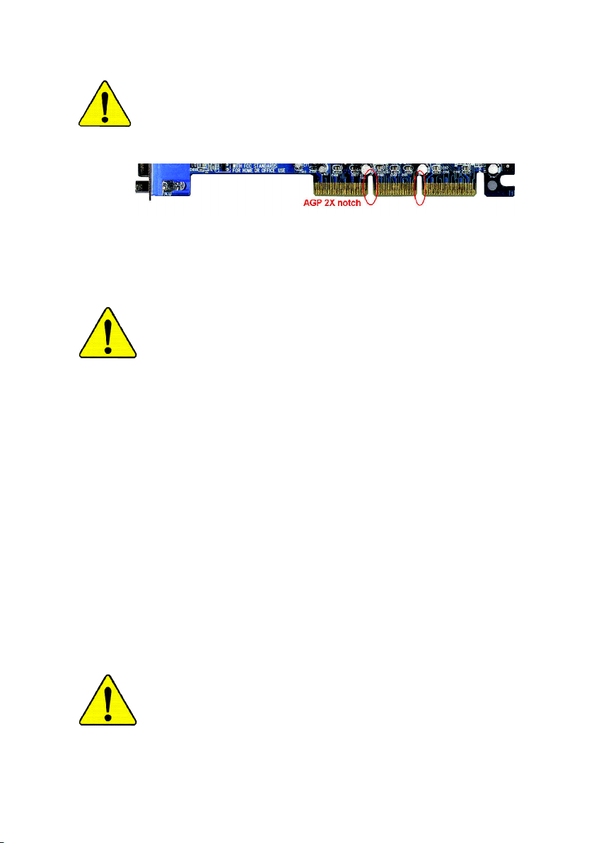
When you installing AGP card, please make sure the following
notice is fully understood and practiced. If your AGP card has
"AGP 4X/8X(1.5V) notch"(show below), please make sure your AGP
card is AGP 4X/8X(1.5V).
AGP 4X/8X notch
Caution: AGP 2X card is not supported by SiS® 655FX. You might
experience system unable to boot up normally. Please insert an
AGP 4X/8X card.
Example 1: Diamond Vipper V770 golden finger is compatible with
2X/4X mode AGP slot. It can be switched between AGP 2X(3.3V) or
4X(1.5V) mode by adjusting the jumper. The factory default for this card
is 2X(3.3V). The GA-8S655FX Ultra/GA-8S655FX (-L)
(or any AGP 4X only) motherboardsmight not function properly, if you
install this card without switching the jumper to 4X(1.5) mode in it.
Example 2: Some ATi Rage 128 Pro graphics cards made by "Power
Color", the graphics card manufacturer & some SiS 305 cards, their
golden finger is compatible with 2X(3.3V)/4X(1.5V) mode AGP slot, but
they support 2X(3.3V) only. The GA-8S655FX Ultra/GA-8S655FX (-L)
(or any AGP 4X only) motherboards might not function properly, If you
install this card in it.
Note : Although Gigabyte's AG32S(G) graphics card is based on
ATi Rage 128 Pro chip, the design of AG32S(G) is compliance with
AGP 4X(1.5V) specification. Therefore, AG32S (G)will work fine with
SiS® 655FX based motherboards.
Before you install PCI cards, please remove the Dual BIOS label from
PCI slots if there is one.
Page 2
M The author assumes no responsibility for any errors or
omissions that may appear in this document nor does the
author make a commitment to update the information
contained herein.
M Third-party brands and names are the property of their
respective owners.
M Please do not remove any labels on motherboard, this may
void the warranty of this motherboard.
M Due to rapid change in technology, some of the specifications
might be out of date before publication of this booklet.
Page 3

Ausschla ger Weg 41, 1F, 20537 Hamburg, Germany
( description of the apparatus, system, installation to which it refers)
(reference to the specification under which con formity is declared)
in accordance with 89/336 EEC-EMC Directive
o EN 55011 Limits and methods of measurement
o EN 55013
o EN 55014 Limits and methods of measurement
o EN 55015 Limits and methods of measurement
o EN 55020
T EN 55022 Limits and methods of measurement
o DIN VDE 0855
o part 10
o part 12
T CE marking
o EN 60065
o EN 60335
of radio disturbance characteristics of
industrial,scientific and medical (ISM
high frequency equipment
Limits and methods of measurement
of radio disturbance characteristics of
broadcast receivers and associated
equipment
of radio disturbance characteristics of
household electrical appliances,
portable tools and similar electrical
apparatus
of radio disturbance characteristics of
fluorescent lamps and luminaries
Immunity from radio interference of
broadcast receivers and associated
equipment
of radio disturbance characteristics of
information technology equipment
Cabled distribution systems; Equipment
for receiving and/or distribution from
sound and television signals
The manufacturer also declares the conformity of above mentioned product
with the actual required safety standards in accordance with LVD 73/23 EEC
Safety requirements for mains operated
electronic and related apparatus for
household and similar general use
Safety of household and similar
electrical appliances
(Stamp)
Declaration of Conformity
We, Manufacturer/Importer
(full address)
G.B.T. Technology Träding GMbH
declare that the product
Mother Board
GA-8S655FX Ultra/GA-8S655FX(-L)
is in conformity with
o EN 61000-3-2*
T EN 60555-2
o EN 61000-3-3* Disturbances in supply systems cause
T EN 60555-3
T EN 50081-1
T EN 50082-1
o EN 55081-2
o EN 55082-2
o ENV 55104
o EN50091-2
(EC conformity marking)
o EN 60950
o EN 50091-1
Manufacturer/Importer
Date : August 28, 2003
Disturbances in supply systems cause
by household appliances and similar
electrical equipment “Harmonics”
by household appliances and similar
electrical equipment “Voltage fluctuations”
Generic emission standard Part 1:
Residual commercial and light industry
Generic immunity standard Part 1:
Residual commercial and light industry
Generic emission standard Part 2:
Industrial environment
Generic emission standard Part 2:
Industrial environment
lmmunity requirements for household
appliances tools and similar apparatus
EMC requirements for uninterruptible
power systems (UPS)
Safety for information technology equipment
including electrical bussiness equipment
General and Safety requirements for
uninterruptible power systems (UPS)
Signature:
Name:
Timmy Huang
Timmy Huang
Page 4

DECLARATION OF CONFORMITY
Per FCC Part 2 Section 2.1077(a)
Responsible Party Name:
Add ress:
Phone/Fax No:
hereby declares that the product
Produ ct Name:
Model Nu mber:
Conforms to the following specifications:
FCC Part 15, Subpart B, Section 15.107(a) and Section 15.109
(a),Class B Digital D evice
Supplementary Information:
This device complies with part 15 of the FCC Rules. Operation is
subject to the following two conditions: (1) This device may not
cause harmful and (2) this device must accept any inference received,
including that may cause undes ired operation.
Representative Person’s Name:
G.B.T. INC. (U .S.A.)
17358 Railroad Street
City of Indu stry, CA 91748
(818) 854-9338/ (818) 854-9339
Motherboard
GA-8S655FX Ultra
/GA-8S655FX (-L)
ERIC LU
Signature:
Date:
Eric Lu
August 28, 2003
Page 5

GA-8S655FX Ultra/GA-8S655FX(-L)
P4 Titan Series Motherboard
USER'S MANUAL
Pentium®4 Processor Motherboard
Rev. 1005
12ME-8S655FXU-1005
Page 6

Table of Content
English
Item Checklist ......................................................................................4
Chapter 1 Introduction .........................................................................5
Chapter 2 Hardware Installation Process ............................................ 11
Chapter 3 BIOS Setup ....................................................................... 37
Features Summary .......................................................................................... 5
GA-8S655FX Ultra/GA-8S655FX(-L) Motherboard Layout ........................... 8
Block Diagram .................................................................................................. 9
Step 1: Install the Central Processing Unit (CPU) ....................................... 12
Step 1-1: CPU Installation ........................................................................................... 12
Step 1-2 : CPU Cooling Fan Installation ...................................................................... 13
Step 2: Install memory modules ................................................................... 14
Step 3: Install expansion cards ..................................................................... 17
Step 4: Connect ribbon cables, cabinet wires, and power supply .............. 18
Step 4-1: I/O Back Panel Introduction ..........................................................................18
Step 4-2: Connectors & Jumper Setting Introduction ....................................................20
The Main Menu (For example: BIOS Ver. : 8S655FX Ultra F1a) ................ 38
Standard CMOS Features ............................................................................. 40
Advanced BIOS Features .............................................................................. 43
Integrated Peripherals .................................................................................. 45
Power Management Setup ............................................................................ 50
- 2 -GA-8S655FX Series Motherboard
Page 7

English
PnP/PCI Configurations................................................................................. 52
PC Health Status ........................................................................................... 53
Frequency/Voltage Control ............................................................................ 54
Top Performance ............................................................................................ 57
Load Fail-Safe Defaults ................................................................................. 58
Load Optimized Defaults ............................................................................... 59
Set Supervisor/User Password ..................................................................... 60
Save & Exit Setup .......................................................................................... 61
Exit Without Saving ...................................................................................... 62
Chapter 4 Technical Reference .......................................................... 65
@ BIOSTM Introduction .................................................................................. 65
Easy Tune
Face-WizardTM Utilities Installation
Flash BIOS Method Introduction ................................................................... 68
2-/4-/6-Channel Audio Function Introduction ............................................... 89
Jack-Sensing Introduction ............................................................................. 95
UAJ Introduction ............................................................................................ 97
Xpress Recovery Introduction ....................................................................... 99
Serial ATA RAID BIOS Utility Operation Introduction ................................. 102
TM
4 Introduction ............................................................................ 66
(j)
................................................................................................... 67
Chapter 5 Appendix ......................................................................... 111
j For GA-8S655FX Ultra only.
- 3 -
Table of Content
Page 8
Item Checklist
English
Computer motherboards and expansion cards contain very delicate Integrated Circuit (IC) chips. To
protect them against damage from static electricity, you should follow some precautions whenever you
work on your computer.
Installing the motherboard to the chassis…
are no slots to attach the spacers, do not become alarmed you can still attach the spacers to the
mounting holes. Just cut the bottom portion of the spacers (the spacer may be a little hard to cut off, so
be careful of your hands). In this way you can still attach the motherboard to the base without worrying
about short circuits. Sometimes you may need to use the plastic springs to isolate the screw from the
motherboard PCB surface, because the circuit wire may be near by the hole. Be careful, don't let the
screw contact any printed circuit write or parts on the PCB that are near the fixing hole, otherwise it may
damage the board or cause board malfunctioning.
The GA-8S655FX Ultra or GA-8S655FX-L 2 Port USB Cable x 1
or GA-8S655FX motherboard 4 Port USB Cable x 1
(kl)
IDE cable x 1
CD for motherboard driver & u tility IEEE1394 + USB Cable x 1
GA-8S655FX Ultra/GA-8S655FX(-L) user's m anual Audio Combo Kit x 1
I/O Shield (SURROUND- Kit + SPDIF Out KIT)
Quick PC Insta llation Guide Motherboard Settings Label
GigaRAID Manual
GC-SATA Card (Optional) SATA cable x 2
(Manual; SATA cable x1; Power cable x 1) Seria l ATA Power Cable x 1
(j)
/x 3
, Floppy cable x 1 SPDIF-KIT x 1 (SPDIF Out K IT)
(j)
SATA RAID M anual
(kl)
(j)
1. Unplug your computer when working on the inside.
2. Use a grounded wrist strap before handling computer components. If you do not have
one, touch both of your hands to a safely grounded object or to a metal object, such as
the power supply case.
3. Hold components by the edges and try not touch the IC chips, leads or connectors, or
other components.
4. Place components on a grounded antistatic pad or on the bag that came with the
components whenever the components are separated from the system.
5. Ensure that the ATX power supply is switched off before you plug in or remove the ATX
ower connector on the motherboard.
If the motherboard has mounting holes, but they don't line up with the holes on the base and there
(j)
j For GA-8S655FX Ultra only. k For GA-8S655FX-L only. l For GA-8S655FX only.
- 4 -GA-8S655FX Series Motherboard
Page 9

English
Chapter 1 Introduction
Features Summary
Form Factor — 30.5cm x 24.4cm ATX size form factor, 4 layers PCB.
CPU — Socket 478 for Intel® Micro FC-PGA2 Pentium® 4 processor
— Support Intel® Pentium® 4 (Northwood, Prescott) processor
— Support Intel® Pentium® 4 Processor with HT Technology
— Intel Pentium®4 800/533/400 MHz FSB
— 2nd cache depends on CPU
Chipset — SiS 655FX Host/Memory controller
— SiS 964 MuTIOL Media I/O
Memory — 4 184-pin DDR DIMM sockets
— Supports Dual channel DDR400/DDR333/DDR266 DIMM
— Supports 128MB/256MB/512MB/1GB unbuffered DRAM
— Supports up to 4GB DRAM (Max)
I/O Control — IT8705
Slots — 1 AGP slot supports 8X/4X mode
— 5 PCI slot supports 33MHz & PCI 2.3 compliant
On-Board IDE — 2 IDE controllers provides IDE HDD/CD-ROM (IDE1, IDE2) with
PIO, Bus Master (Ultra DMA33/ATA66/ATA100/ATA133)
operation modes
— IDE3
(j)
and IDE4
(j)
compatible with RAID,
Ultra ATA133/100, IDE
On-Board Peripherals — 1 Floppy port supports 2 FDD with 360K, 720K,1.2M, 1.44M
and 2.88M bytes.
— 1 Parallel port supports Normal/EPP/ECP mode
— 2 Serial ports (COMA&COMB)
— 8 USB 2.0/1.1 ports (4 x Rear, 4 xFront by cable)
— 3 IEEE1394 ports (by cable)
— 1 Front Audio Connector
— 1 IrDA connector for IR
Hardware Monitor — CPU/System Fan Revolution detect
— CPU temperature detect
— System Voltage detect
(Note 1)
to be continued......
(Note 1) Due to standard PC architecture, a certain amount of m emory is reserved for system
usage and the refore the actual mem ory size is less than the s tated amount.
For example, 4 GB of mem ory size will instead be shown as 3.xxGB mem ory during
system startup.
j For GA-8S655FX Ultra only.
Introduction- 5 -
Page 10

On-Board Sound — Realtek ALC658 UAJ CODEC
English
On-Board LAN
On-Board IDE RAID
On-Board SATA RAID — Onboard SiS 964
On-Board IEEE1394 — Built-in TI TSB43AB23
PS/2 Connector — PS/2 Keyboard interface and PS/2 Mouse interface
(jk)
— Line Out / 2 front speaker
— Line In / 2 rear speaker(by s/w switch)
— Mic In / center& subwoofer(by s/w switch)
— SPDIF Out /SPDIF In
— CD_In / AUX_IN / Game Port
(jk)
(j)
Chipset
(k)
Chipset
— Build in RTL8110S
— Build in RTL8100C
— 1 RJ45 port
(j)
— Onboard GigaRAID IT8212F chipset
— Supports data striping (RAID 0) or mirroring (RAID 1) or
striping+mirroring (RAID 0 + RAID 1)
— Support JBOD function
— Supports concurrent dual ATA133 IDE controller operation
— Support ATAPI mode for HDD
— Supports IDE bus master operation
— Support ATA133/RAID mode switch by BIOS
— Displays status and error checking messages during boot-up
— Mirroring supports automatic background rebuilds
— Features LBA and Extended Interrupt 13 drive translation in
controller onboard BIOS
— 2 Serial ATA connectors in 150 MB/s operation mode
— Supports Disk striping (RAID0) or DISK Mirroring (RAID1)
— Support JBOD function
— Supports UDMA up to 150 MB/sec
— UDMA and PIO Modes
— Up to 2 SATA Device
j For GA-8S655FX Ultra only. k For GA-8S655FX-L only.
- 6 -GA-8S655FX Series Motherboard
Page 11

English
BIOS — Licensed AWARD BIOS
— Supports Dual BIOS
— Supports Face Wizard
(j)
/Q-Flash
(j)
Additional Features — PS/2 Keyboard power on by password
— PS/2 Mouse power on
— STR(Suspend-To-RAM)
— AC Recovery
— USB KB/Mouse wake up from S3
— Supports EasyTune 4
— Supports @BIOS
Overclocking — Over Voltage (CPU/DRAM/AGP) by BIOS
— Over Clock (CPU/DRAM/AGP) by BIOS
HT functionality requirement content :
Enabling the functionality of Hyper-Threading Technology for your computer system requires
all of the following platform components:
- CPU: An Intel® Pentium 4 Processor with HT Technology
- Chipset: An SiS® Chipset that supports HT Technology
- BIOS: A BIOS that supports HT Technology and has it enabled
- OS: An operation system that has optimizations for HT Technology
Please set the CPU host frequency in accordance with your processor's specifications.
We don't recommend you to set the system bus frequency over the CPU's specification
because these specific bus frequencies are not the standard specifications for CPU,
chipset and most of the peripherals. Whether your system can run under these specific
bus frequencies properly will depend on your hardware configurations, including CPU,
Chipsets,SDRAM,Cards… .etc.
j For GA-8S655FX Ultra only.
Introduction- 7 -
Page 12
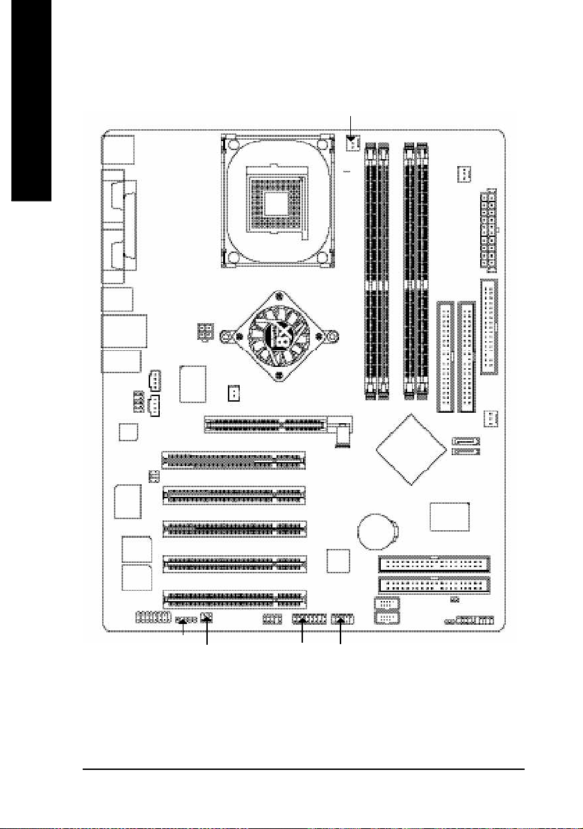
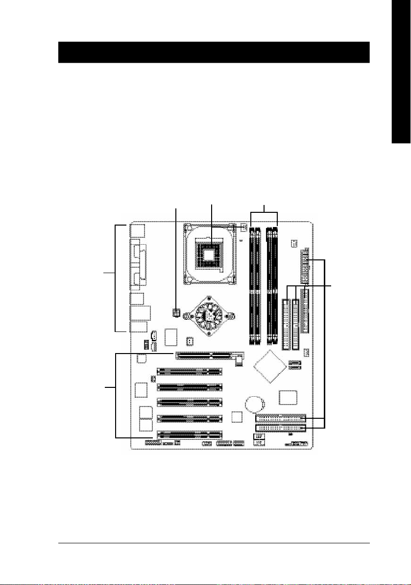
GA-8S655FX Ultra/GA-8S655FX(-L) Motherboard Layout
English
KB_MS
CPU_FAN
PWR_FAN
(j)
COMA
COMB
R_USB
USB_LAN
MIC_IN
LINE_OUT
CODEC
SUR_CEN
IT8705
MAIN
BIOS
BACKUP
BIOS
GAME
LPT
(jk)
CD_IN
LINE_IN
F_AUDIO
AUX_IN
Dual Channel DDR
DDR 400
(j)
ATX_12V
RTL8110S
RTL8100C
P4 Titan
IR
SPDIF_IO
(j)
(k)
NB_FAN
AGP 8X
INFO_LIN K
SOC KET4 78
(j)
SiS 655 FX
F1 _13 94
PCI1
PCI2
PCI3
PCI4
TSB43AB 23
PCI5
F2 _13 94
RAM_LED
Hyper Threading
Support
GA-8S655FX (Ultra/-L)
DDR1
BAT
(j)
DDR3
DDR2
SiS 964
F_U SB2
AGP
IDE4
F_U SB1
IDE2
DDR4
GigaRA ID
IT8212
CL R_PWD
PWR_L ED
IDE1
SYS _FAN
SATA 1
SATA 0
(j)
(j)
IDE3
F_PANEL
ATX
FDD
j For GA-8S655FX Ultra only. k For GA-8S655FX-L only.
- 8 -GA-8S655FX Series Motherboard
Page 13
English
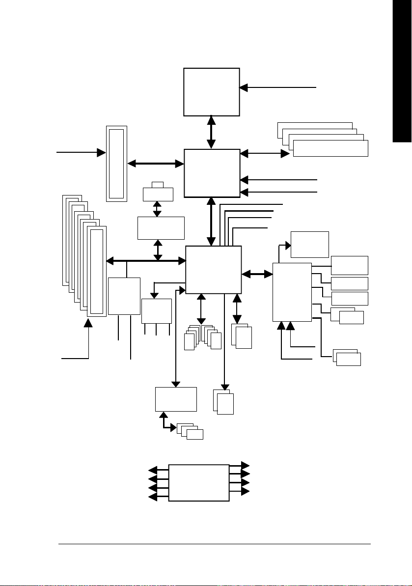
Block Diagram
AGPCLK
(66M Hz)
5 PCI
PCICLK
(33M Hz)
AGP 4X/8X
GigaRAID
IT8212
(j)
IDE4
IDE3
RJ45
RTL8110S
RTL8100C
(j)
AC97
CODEC
MIC
(j)
(jk)
(j)
(k)
AC97 Link
LINE-IN
LINE-OUT
TI
TSB43AB23
Pentium 4
Socket 478
CPU
SiS 655FX
SiS 964
8 USB
Ports
CPUCLK+/- (100/133/200 MHz)
System Bus
400/533/800 M Hz
266/333/400 M Hz
ZCLK (66/133M Hz)
HCLK+/- (100/133/200MHz)
48 MHz
LPC BUS
ATA33/66/100
/133 IDE Channels
Serial ATA
Channels
66/133 MHz
33 MHz
14.318 MHz
IT8705
33 MHz
BIOS
24 MHz
DDR
Game Port
Floppy
LPT Port
PS/2
KB/Mouse
COM
Ports
IEEE 1394 Ports
PCICLK (33MHz)
USBCLK (48MHz)
14.318 MHz
33 MHz
CLK GEN
j For GA-8S655FX Ultra only. k For GA-8S655FX-L only.
ZCLK (66/133M Hz)
CPUCLK+/- (100/133/200MHz)
AGPCLK (66MHz)
HCLK+/- (100/133/200MHz)
Introduction- 9 -
Page 14

English
- 10 -GA-8S655FX Series Motherboard
Page 15
English
Chapter 2 Hardware Installation Process
To set up your computer, you must complete the following steps:
Step 1- Install the Central Processing Unit (CPU)
Step 2- Install memory modules
Step 3- Install expansion cards
Step 4- Connect ribbon cables, cabinet wires, and power supply
Step 4
Step 3
Step 4
Step 1
Step 2
Step 4
Congratulations you have accomplished the hardware installation!
Turn on the power supply or connect the power cable to the power outlet. Continue with the BIOS/
software installation.
- 11 - Hardware Installation Process
Page 16
Step 1: Install the Central Processing Unit (CPU)
English
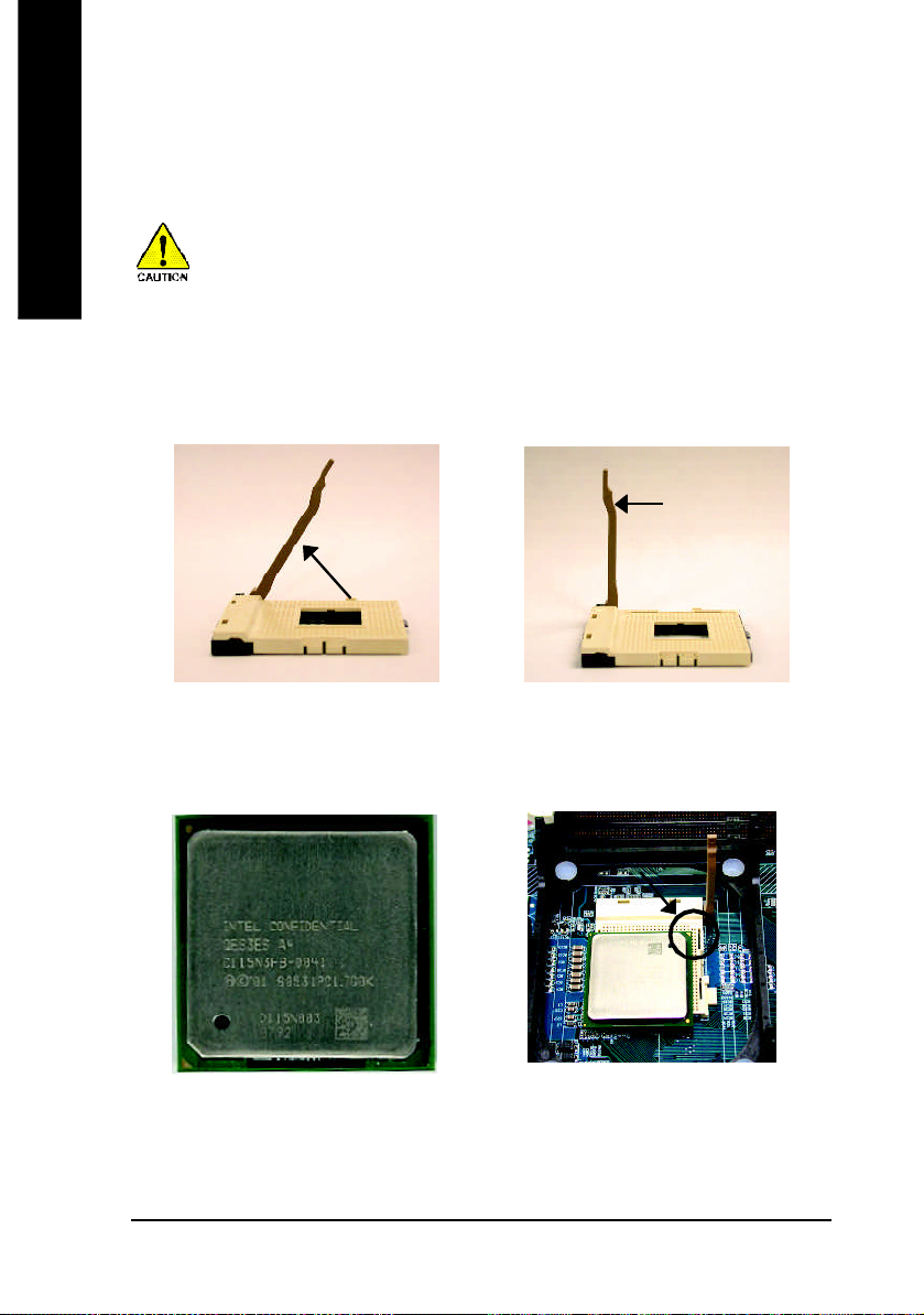
Step 1-1: CPU Installation
Before installing the processor, adhere to the following warning:
If you do not match the CPU socket Pin 1 and CPU cut edge well, it will
cause improper installation. Please change the insert orientation.
Please make sure the CPU type is supported by the motherboard.
Angling the
rod to 65
1. Angling the rod to 65-degree maybe feel a
kind of tight , and then continue pull the rod
to 90-degree when a noise "cough" made.
0
Pin1 indicator
3. CPU Top View
Socket
Actuation
Lever
2. Pull the rod to the 90-degree directly.
Pin1 indicator
4. Locate Pin 1 in the socket and look
for a (golden) cut edge on the CPU
upper corner. Then insert the CPU
into the socket.
- 12 -GA-8S655FX Series Motherboard
Page 17
English
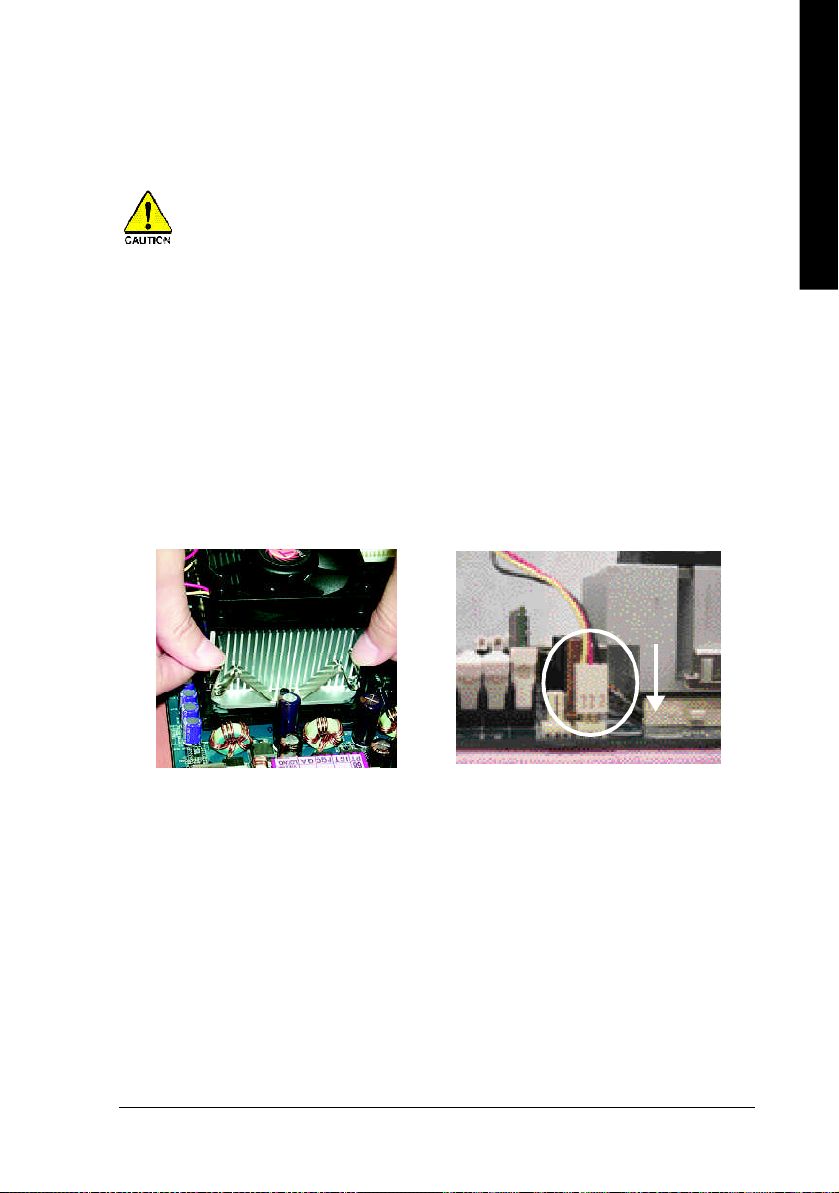
Step 1-2 : CPU Cooling Fan Installation
Before installing the CPU Cooling Fan, adhere to the following warning:
1. Please use Intel approved cooling fan.
2. We recommend you to apply the thermal tape to provide better heat conduction
between your CPU and cooling fan.
(The CPU cooling fan might stick to the CPU due to the hardening of the thermal
paste. During this condition if you try to remove the cooling fan, you might pull the
processor out of the CPU socket alone with the cooling fan, and might damage the
processor. To avoid this from happening, we suggest you to either use thermal
tape instead of thermal paste, or remove the cooling fan with extreme caution.)
3. Make sure the CPU fan power cable is plugged in to the CPU fan connector, this
completes the installation.
Please refer to CPU cooling fan user's manual for more detail installation procedure.
1. Fasten the cooling fan supporting-base
onto the CPU socket on the
mainboard.
2. Make sure the CPU fan is plugged to
the CPU fan connector, than install
complete.
Introduction- 13 -
Page 18
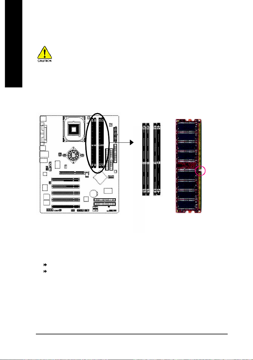
Step 2: Install memory modules
English
The motherboard has 4 dual inline memory module (DIMM) sockets. The BIOS will automatically
detects memory type and size. To install the memory module, just push it vertically into the DIMM
socket. The DIMM module can only fit in one direction due to the notch. Memory size can vary
between sockets.
Before installing the processor and heatsink, adhere to the following warning:
When RAM_LED is ON, do not install/remove DIMM from socket.
Please note that the DIMM module can only fit in one direction due to the one notches.
Wrong orientation will cause improper installation. Please change the insert orientation.
Notch
DDR
GA-8S655FX Ultra/GA-8S655FX(-L) supports the Dual Channel Tec hnology. After operating the Dual
Channel Technology, the bandwidth of M emory Bus will add double up to 6.4GB/s.
GA-8S655FX Ultra/GA-8S655FX(-L) includes 4 DIM M sockets, and each Channel has two DIMM sockets as
following:
Channel A : DIM M 1, DIM M 2
Channel B : DIMM 3, DIMM 4
If yo u want to operate the Dual Channel Technology, please note the following explanations due
to the l imitation of SiS® chipset specificati ons.
1. One/three DDR memory module is installed: The Dual Channel Technology can't operate
when only one or three DDR m emory module is installed.
- 14 -GA-8S655FX Series Motherboard
Page 19

English
2. Two DDR m emory modules are installed (the same mem ory size and type): The Dual
Channel Technology will operate when two me mory modules are inserted in dividually into
Channel A and B. If you install two mem ory modules in the same channel, the Dual Channel
Techno logy will not operate. Additiona lly, you can boot the system only when one of the
mem ory modules is inserted into Channel A or Channel B. On the other hand, the memory
module must be inserted into any sockets.
3. Four DDR mem ory modules are installed: If you install four m emory modules at the same
time, the D ual Channel Technology will operate only when those modules have the same
mem ory size and type.
We'll strongly recommend our user to slot into two DDR memory modules into the DIMMs with the
same color in order for Dual Channel Technology to work.
The following table is for Dual Channel Technology combination:
l Figure 1: D ual Channel Technology (DS: Double Side, SS: Single Side)
DIMM 1 DIMM 2 DIMM 3 DIMM 4
2 me mory module s
4 me mory module s
DS/SS X DS/SS X
DS/SS X X DS/SS
X DS/SS DS/SS X
X DS/SS X DS/SS
DS/SS DS/SS DS/SS DS/SS
- 15 - Hardware Installation Process
Page 20
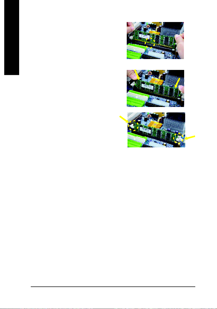
1. The DIMM slot has a notch, so the DIM M memory
English
2. Insert the DIM M m emory module vertically into
3. Close the plastic clip at both edges of the DIM M
DDR Introduction
performance and cost-effective solution that allows easy adoption for memory vendors, OEMs,
and system integrators.
SDRAM architecture, yet make the awesome advances in solving the system performance
bottleneck by doubling the memory bandwidth. Nowadays, with the highest bandwidth of
3.2GB/s of DDR400 memory and complete line of DDR400/333/266/200 memory solutions, DDR
memory is the best choice for building high performance and low latency DRAM subsystem that
are suitable for servers, workstations, and full range of desktop PCs.
module can only fit in one direction.
the DIMM slot. Then push it down.
slots to lock the DIMM module.
Reverse the installation steps when you wish
to remove the DIM M module.
Established on the existing SDRAM infrastructure, DDR (Double Data Rate) memory is a high
DDR memory is a great evolutionary solution for the PC industry that builds on the existing
- 16 -GA-8S655FX Series Motherboard
Page 21
English
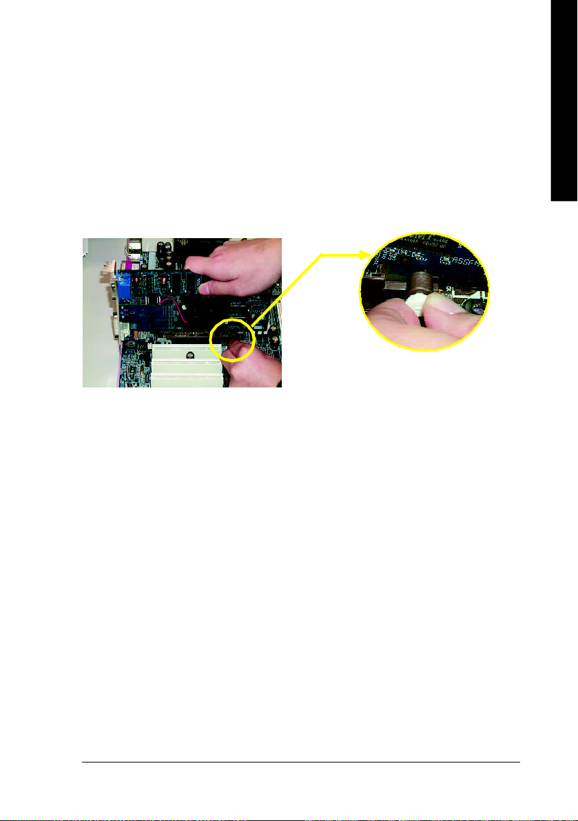
Step 3: Install expansion cards
1. Read the related expansion card's instruction document before install the expansion card into
the computer.
2. Remove your computer's chassis cover, necessary screws and slot bracket from the computer.
3. Press the expansion card firmly into expansion slot in motherboard.
4. Be sure the metal contacts on the card are indeed seated in the slot.
5. Replace the screw to secure the slot bracket of the expansion card.
6. Replace your computer's chassis cover.
7. Power on the computer, if necessary, setup BIOS utility of expansion card from BIOS.
8. Install related driver from the operating system.
Please carefully pull out the sm all white- drawable bar
at the end o f the AGP slot when you try to instal l/
Uninstall the AGP card. Please align the AGP card to
AGP Card
the onboard AGP slot and press firmly down on the slot
.Make sure your AGP card is locked by the sm all whitedrawable bar.
- 17 - Hardware Installation Process
Page 22
Step 4: Connect ribbon cables, cabinet wires, and power
supply
English
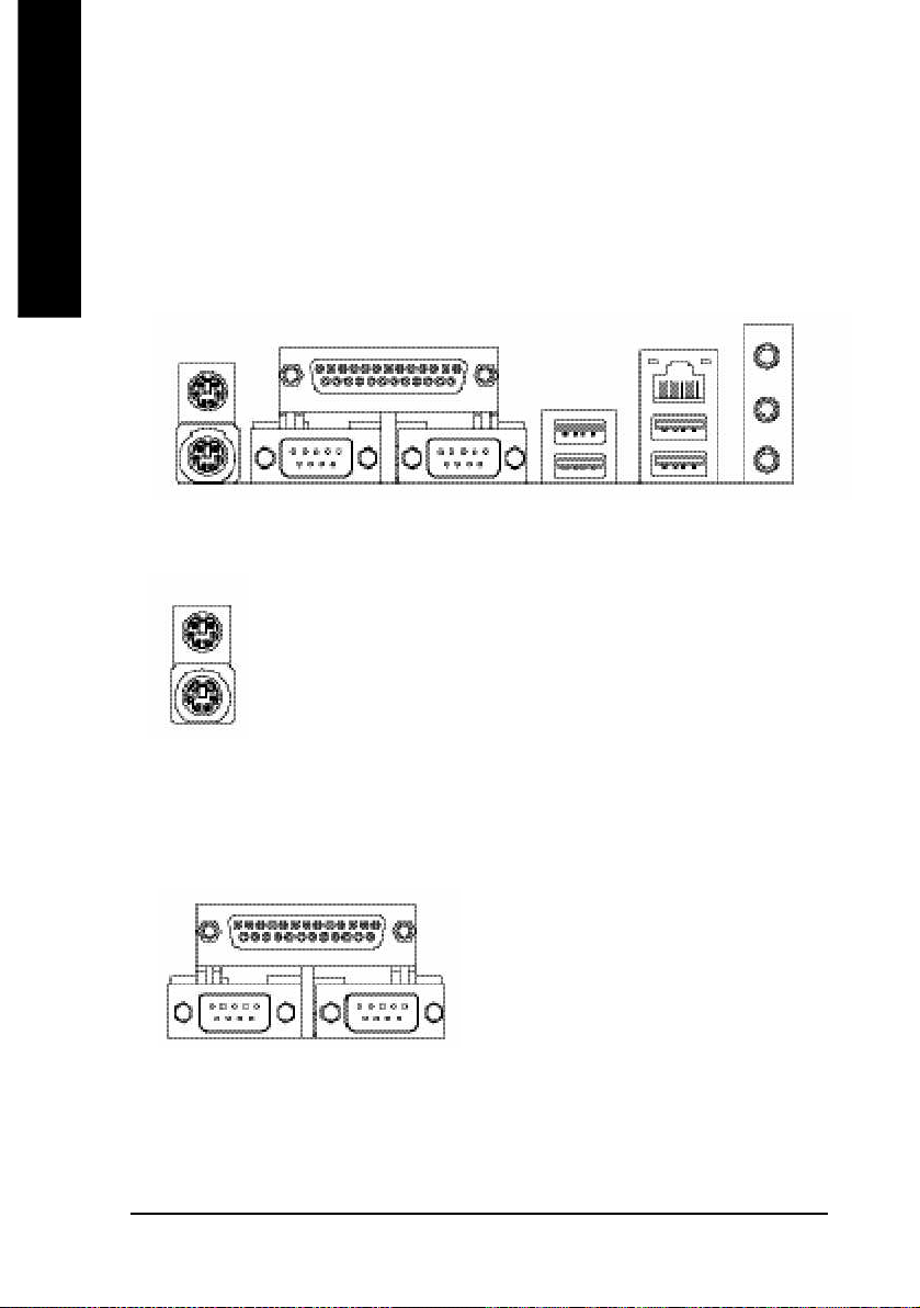
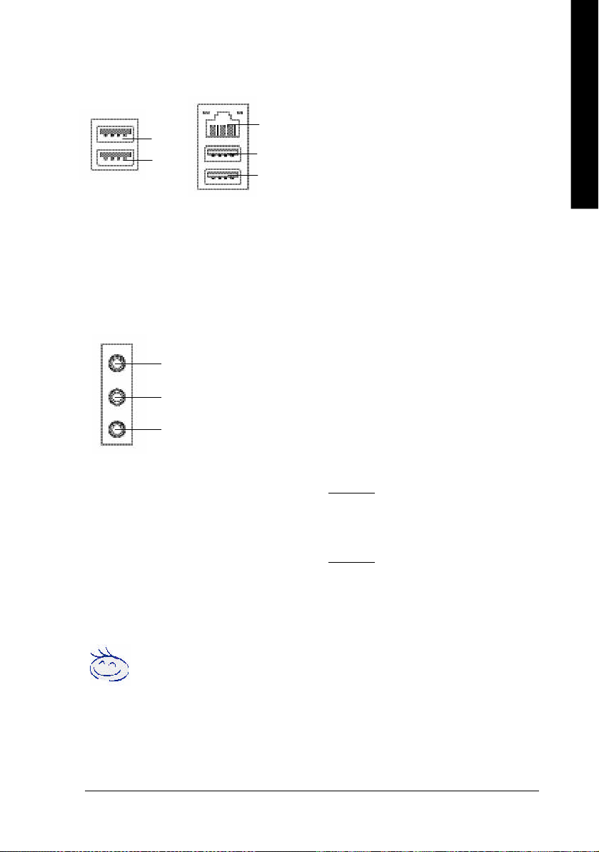
Step 4-1: I/O Back Panel Introduction
u
v
w
u PS/2 Keyboard and PS/2 Mouse Connector
PS/2 Mouse Connector
(6 pin Female)
PS/2 Keyboard Connector
(6 pin Female)
Ø This connector supports standard PS/2
keyboard and PS/2 mouse.
vParallel Port, Serial Port and VGA Port (LPT/COMA/VGA)
Parallel Port
(25 pin Female)
Ø This connector supports 2 standard
COM ports and 1 Parallel port. Device like
printer can be connected to Parallel port;
mouse and modem etc can be connected to
Serial ports.
y
x
COMA COMB
Serial Port (9 pin Male)
- 18 -GA-8S655FX Series Motherboard
Page 23
English
w/x USB / LAN Connector
USB 5
USB 4
LAN
USB 7
USB 6
Ø Before you connect your device(s) into USB
connector(s), please make sure your
(j/k)
device(s) such as USB keyboard,mouse,
scanner, zip, speaker..etc. Have a standard
USB interface. Also make sure your OS
supports USB controller.
If your OS does not support USB controller,
please contact OS vendor for possible patch
or driver upgrade. For more information
please contact your OS or device(s) vendors.
y Audio Connectors
Line In(Rear Speaker)
Line Out(Front Speaker)
MIC In(Center and Subwoofer)
If you want the detail information for 2-/4-/6-channel audio setup
installation, please refer to page 89.
Ø After install onboard audio driver, you may
connect speaker to Line Out jack, micro phone
to MIC In jack.
Device like CD-ROM , walkman etc can be
connected to Line-In jack.
Please note:
You are able to use 2-/4-/6- channel audio
feature by S/W selection.
If you want to enable 6-channel function, you
have 2 choose for hardware connection.
Method1:
Connect "Front Speaker" to "Line Out"
Connect "Rear Speaker" to "Line In"
Connect "Center and Subwoofer" to "MIC Out".
Method2:
You can refer to page 28, and contact your
nearest dealerfor optional SUR_CEN cable.
j For GA-8S655FX Ultra only. k For GA-8S655FX-L only.
- 19 - Hardware Installation Process
Page 24
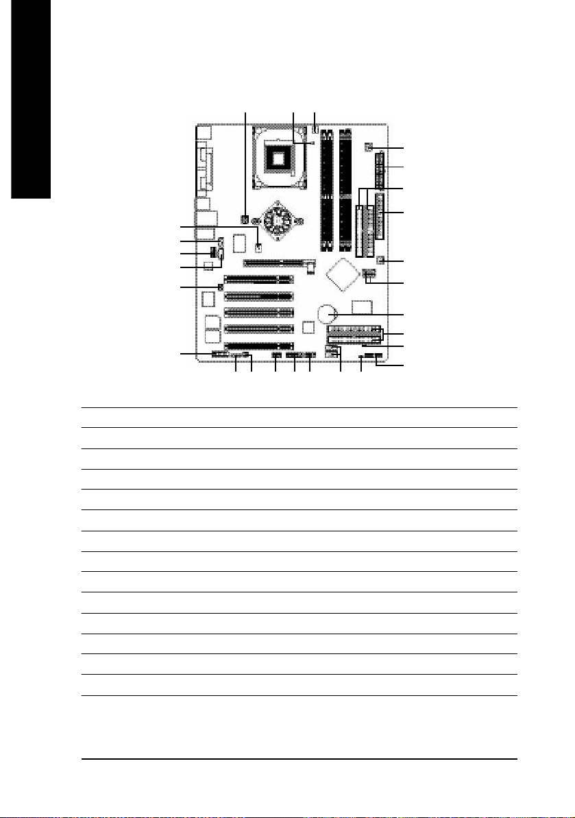
Step 4-2: Connectors & Jumper Setting Introduction
English
1 3
(j)
6
16
14
17
15
21
10
24182019
23
22
11
1) ATX_12V 15) SUR_CEN
2) ATX 16) CD_IN
3) CPU_FAN 17) AUX_IN
4) SYS_FAN 18) SPDIF_IO
5) PWR_FAN
6) NB_FAN
(j)
(j)
19) IR
20) F_USB1/F_USB2
7) IDE1/IDE2 21) GAME
8) IDE3/IDE4
(j)
22) INFO_LINK
9) FDD 23) F1_1394
10) RAM_LED 24) F2_1394
11) PWR_LED 25) SATA0/SATA1
12) BAT 26) CLR_PWD
13) F_PANEL
14) F_AUDIO
(j)
5
2
7
9
4
25
12
(j)
8
26
13
j For GA-8S655FX Ultra only. k For GA-8S655FX-L only.
- 20 -GA-8S655FX Series Motherboard
Page 25
English
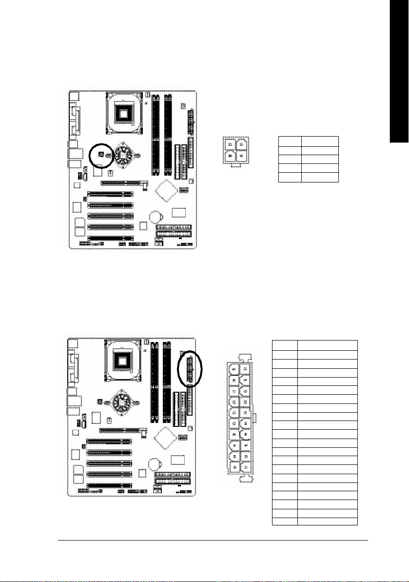
1) ATX_12V (+12V Power Connector)
This connector (ATX _12V) suppliesthe CPU operation voltage (Vcore). If this " ATX_ 12V connector" is
not connected, system cannot boot.
2
4
1
3
Pin No. Definition
1 GND
2 GND
3 +12V
4 +12V
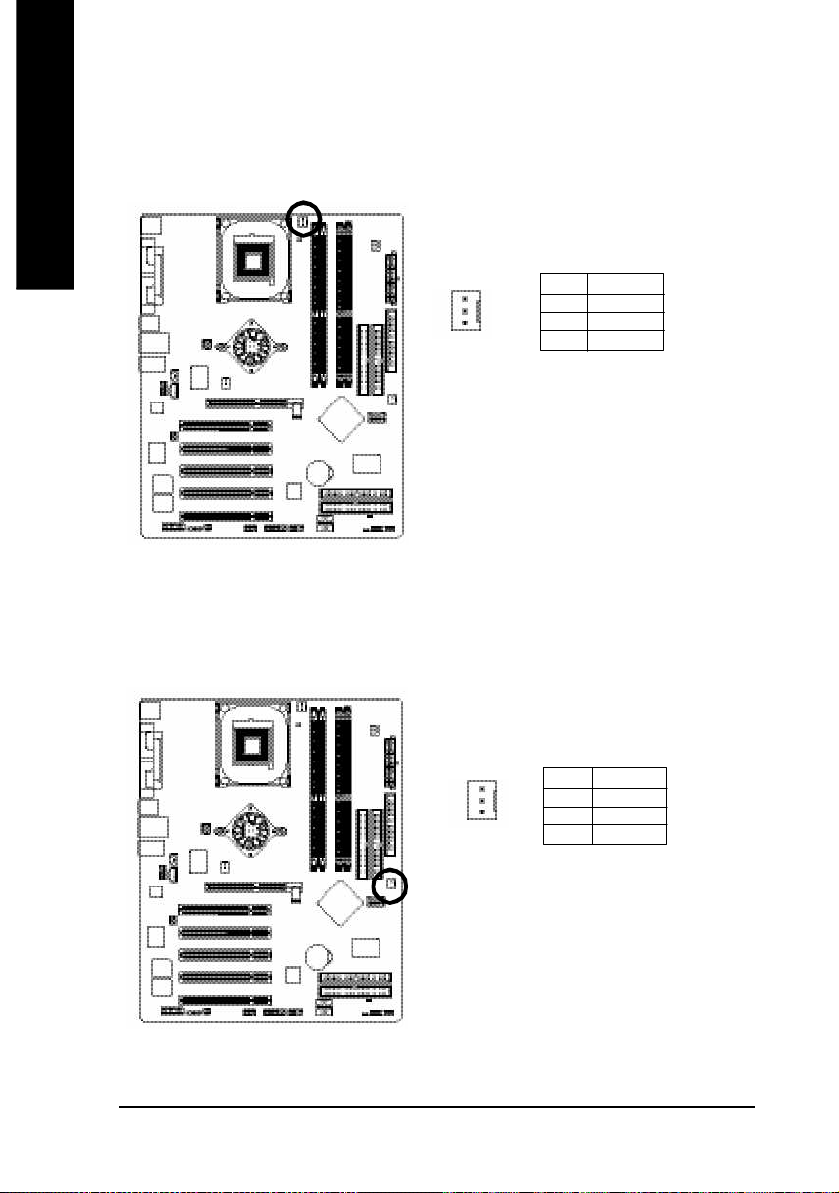
2) ATX (ATX Power)
AC power cord should only be connected to your power supply unit after ATX power cable and other
related devices are firmly connected to the mainboard.
Pin No. Definition
1 3.3V
10
1
- 21 - Hardware Installation Process
2 3.3V
20
3 GND
4 VCC
5 GND
6 VCC
7 GND
8 Power Good
9 5V SB(stand by +5 V)
10 +12V
11 3.3V
12 -12V
13 GND
14 PS_O N(softOn/ Off)
11
15 GND
16 GND
17 GND
18 -5V
19 VCC
20 VCC
Page 26
3) CPU_FAN (CPU FAN Connector)
English
4) SYS_FAN (System FAN Connector)
Please note, a proper installation of the CPU cooler is essential to prevent the CPU from running
under abnormal condition or dam aged by overheating.The CPU fan connector supports Max.
current up to 600 mA.
Pin No. Definition
1 GND
1
This connector allows you to link with the cooling fan on the system case to lower the system
temperature.
2 +12V
3 Sense
Pin No. Definition
1 GND
1
- 22 -GA-8S655FX Series Motherboard
2 +12V
3 Sense
Page 27
English
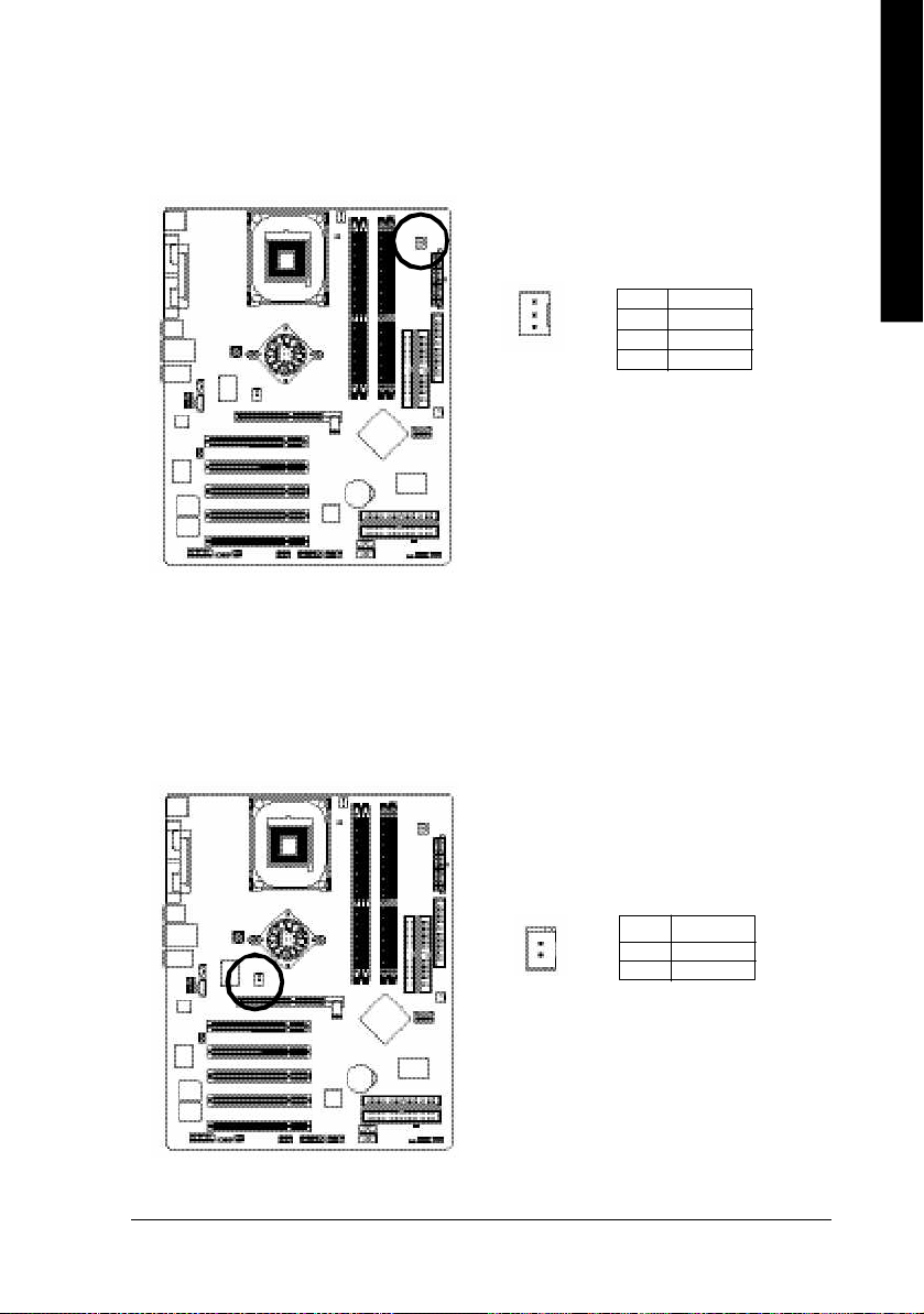
5) PWR_FAN (Power Fan Connector)
This connector allows you to link with the cooling fan on the system case to lower the system
temperature.
(j)
Pin No. Definition
1
1 GND
2 +12V
3 Sense
6) NB_FAN
If you installed wrong direction, the Chip Fan will not work. Sometimes will damage the Chip Fan.
(Usually black cable is GND)
Note: If the NorthBridg e on the motherboard has a fan sink, then the motherboard contains a
NB_FAN connector.
(j)
1
Pin No. Definition
1 VCC
2 GND
j For GA-8S655FX Ultra only.
- 23 - Hardware Installation Process
Page 28
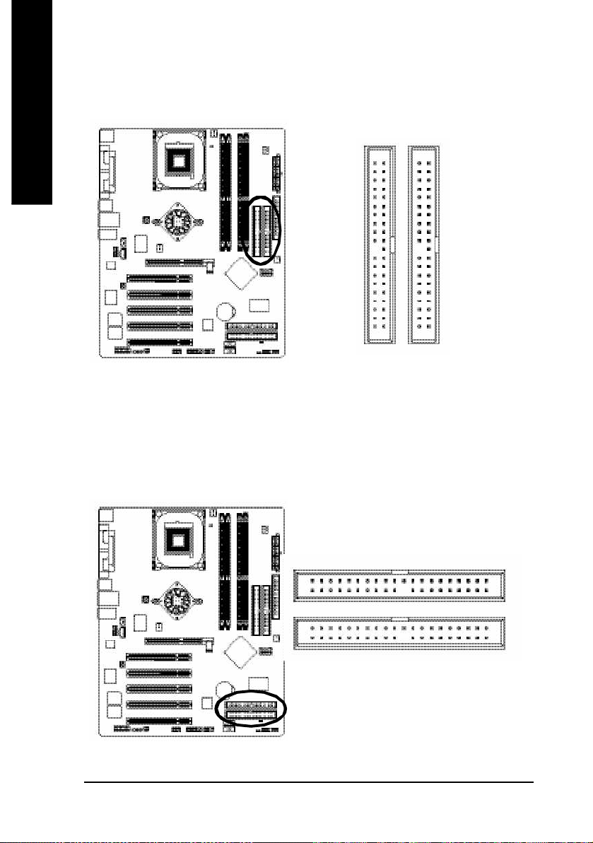
7) IDE1/ IDE2(IDE1/IDE2 Connector)
English
Please connect first harddisk to IDE1 and connect CDROM to IDE2. The red stripe of the ribbon cable
must be the same side with the Pin1.
40
2
IDE2
8) IDE3 / IDE4 (RAID/ATA133, Green Connector)
Important Notice: The red stripe of the ribbon cable must be the same side with the Pin1. If you wish to
use IDE3 and IDE4, ple ase use it in unity with BIOS (either RAID or ATA133). Then, install the correct
driver to have proper operation. For deta ils, please refer to the GigaRAID manual.
(j)
39
1
IDE1
139
j For GA-8S655FX Ultra only.
IDE3
IDE4
240
- 24 -GA-8S655FX Series Motherboard
Page 29
English
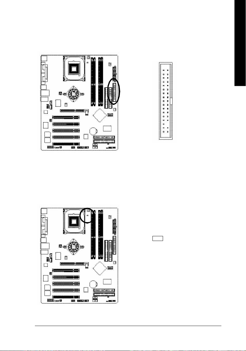
9) FDD (Floppy Connector)
Please connect the floppy drive ribbon cables to FDD. It supports 360K,720K,1.2M,1.44M and
2.88Mbytes floppy disk types. The red stripe of the ribbon cable m ust be the same side with the Pin1.
34
2
33
1
10) RAM_LED
Do not remove memory modules while RAM LED is on. It might cause short or other unexpected
damages due to the stand by voltage. Remove memory modules only when AC Power cord is disconnected.
+-
- 25 - Hardware Installation Process
Page 30
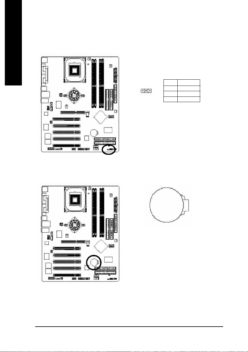
11) PWR_LED
English
12) BAT (Battery)
PWR_LED is connect with the system power indicator to indicate whether the system is on/off. It will blink
when the system enters suspend mode. If you use dual color LED, power LED will turn to another color.
Pin No. Definition
1
1 MPD+
2 MPD3 MPD-
If yo u want to erase CMOS...
1.Turn OFF the computer a nd unplug the power cord.
2.Remov e the battery, wait for 30 second.
3.Re-install the battery.
4.Plug the power cord and turn ON the com puter.
- 26 -GA-8S655FX Series Motherboard
+
CAUTION
v Danger of explosion if battery is incorrectly
replaced.
v Replace only with the same or equivalent
type recom mended by the m anufacturer.
v Dispose of used batteries according to the
manufacturer's instructions.
Page 31

English
13) F_PANEL (2x10 pins connector)
Please connect the power LED, PC peaker, reset switch and power switch etc of your chassis front panel
to the F_PANEL connector according to the pin assignm ent above.
Mes sa ge LE D/ Po we r/
Sleep LED
MPDMPD+
IDE H ard Disk
Activ e LED
HD (IDE Hard Disk Ac tive LED) Pin 1: LED anode(+)
(Blue) Pin 2: LED cathode(-)
SPEAK (Speaker Connector) Pin 1: VCC(+)
(Amber) Pin 2- Pin 3: NC
Pin 4: Data(-)
RES (Reset Switch) Open: Normal Operation
(Green) Close: Reset Hardware System
PW (Soft Power Connector) Open: Normal Operation
(Red) Close: Power On/Off
MSG(Message LED/Power/ Pin 1: LED anode(+)
Sleep LED)(Yellow) Pin 2: LED cathode(-)
NC( Purple) NC
HD+
HD-
Soft Po wer
Connector
1
2
1
1
Reset Swi tch
RSE-
PW+
1
RSE +
PW-
Speaker
Connector
SPE AK-
SP EAK +
1
1
NC
20
19
- 27 - Hardware Installation Process
Page 32

14) F_AUDIO (F_AUDIO Connector)
English
15) SUR_CEN
If you want to use Front Audio connector, you must remove 5-6, 9-10 Jum per. In order to utilize the
front audio header, your chassis must have front audio connector. Also please make sure the pin
assigment on the cable is the sam e as the pin assigment on the MB header. To find out if the chassis
you are buying support front audio connector, please contact your dealer.Please note, you can have the
alternati ve of using front audio connector or of using rear aud io connector to pl ay sound.
Pin No. Definition
1 MIC
10
9
2
1
Please contact your nearest dealer for optional SUR_CEN cable.
2 GND
3 REF
4 POWER
5 FrontAudio(R)
6 RearAudio(R)
7 Reserved
8 No Pin
9 FrontAudio (L)
10 RearAudio(L)
Pin No. Definition
1 SUR OUT L
1
2
5
6
- 28 -GA-8S655FX Series Motherboard
2 SUR OUT R
3 GND
4 No Pin
5 CENTER_OUT
6 BASS_OUT
Page 33

English
16) CD_IN (CD IN, Black)
Connect CD-ROM or DVD-ROM audio out to the connector.
1
17) AUX_IN (AUX In Connector)
Connect other device(such as PCI TV Tunner audio out)to the connector.
Pin No. Definition
1 CD-L
2 GND
3 GND
4 CD_R
Pin No. Definition
1
- 29 - Hardware Installation Process
1 AUX-L
2 GND
3 GND
4 AUX_R
Page 34

18) SPDIF_IO (SPDIF In/Out)
English
19) IR
The SPDIF output is capable of providing digital audio to external speakers or com pressed AC3 data to
an external Dolby Digital Decoder. Use this featu re only when your stereo system has digita l input
function. Use SPDIF IN featu re only when your device has digital output function.
Be careful with the polarity of the SPDIF_IO connector. Check the pin assignment carefully while you
connect the SPDIF_IO cable, incorrect connectio n between the cable and connector will make the
device unable to work or even damage it. For optional SPDIF_IO cable, please contact your local
dealer.
Pin No. Definition
1 VCC
62
5
1
Make sur e the pin 1 on the IR device is aling with pin one the connector. To enable the IR fun ction on
the board, you are required to purchase an option IR module. Be careful with the polarity of the IR
connector. F or optional IR cable, please contact your l ocal dealer.
2 No Pin
3 SPDIF
4 SPDIFI
5 GND
6 GND
Pin No. Definition
1 VCC
2 No Pin
1
- 30 -GA-8S655FX Series Motherboard
3 IR Data Input
4 GND
5 IR Data Output
Page 35

English
20) F_ USB1 / F_USB2(Front USB Connector, Yellow )
Be careful with the polarity of the front USB connector. Check the pin assignment whil e you
connect the front USB cable. Please contact your nea rest dealer for optional front USB cable.
Be careful with the polarity of the F_USB connector. Check the pin assignment carefully while you
connect the F_USB cable, incorrect connection between the cable and connector will m ake the device
unable to work or even damage it. For optional F_USB cable, please contact your local dealer.
Pin No. Definition
1 Power
2 Power
2 10
1 9
3 USB0 DX-/USB2 DX4 USB1 Dy-/USB3 Dy5 USB0 DX+/USB2 DX+
6 USB1 Dy+/USB3 Dy+
7 GND
8 GND
9 No Pin
10 NC
21) GAME (GAME Connector)
This connector supports joystick, MIDI keyboard and other relate audio devices.
Pin No. Definition
1 VCC
2 GRX1_R
3 GND
4 GPSA2
5 VCC
162
1 15
6 GPX2_R
7 GPY2_R
8 MSI_R
9 GPSA1
10 GND
11 GPY1_R
12 VCC
13 GPSB1
14 MSO_R
15 GPSB2
16 No Pin
- 31 - Hardware Installation Process
Page 36

22) INFO_LINK
English
23) F1_1394 (IEEE 1394 Connector)
This connector allows you to connect som e external devices to provide you extra function.
Pin No. Definition
1 SMBCLK
2 VCC
2
1 9
10
3 SMBDATA
4 GPIO
5 GND
6 GND
7 No Pin
8 NC
9 +12V
10 +12V
Please Note: Serial interface standard set by Institute of Electrical and Electronics Engineers, which
has features like high speed, high bandwidth and h ot plug.
Be careful with the polarity of the IEEE1394 connector. Check the pin assignment carefully whil e you
connect the IEEE1394 cable, incorrect connection between the cable and connector will m ake the
device unable to work or even damage it. For optional IEEE1394 cable, please contact your local
dealer.
Pin No. Definition
1 Power
2 Power
3 TPA0+
2
1
16
15
4 TPA05 GND
6 GND
7 TPB0+
8 TPB09 Power
10 Power
11 TPA1+
12 TPA113 GND
14 No Pin
15 TPB1+
16 TPB1-
- 32 -GA-8S655FX Series Motherboard
Page 37

English
24) F2_1394 (IEEE 1394 Connector)
Please Note: Serial interface standard set by Institute of Electrical and Electronics Engineers, which
has features like high speed, high bandwidth and h ot plug.
Be careful with the polarity of the IEEE1394 connector. Check the pin assignment carefully whil e you
connect the IEEE1394 cable, incorrect connection between the cable and connector will m ake the
device unable to work or even damage it. For optional IEEE1394 cable, please contact your local
dealer.
Pin No. Definition
2
10
9
1
1 TPA2+
2 TPA23 GND
4 GND
5 TPB2+
6 TPB27 Power
8 Power
9 No Pin
10 GND
25) SATA0/SATA1 (Serial ATA Connector)
You can connect the Serial ATA device to this connector, it provides you high speed transfe r rates
(150M B/sec). If you wish to use RAID function, please use it in unity with BIOS and install the correct
driver to have proper operation. For details, please refer to page 102.
Pin No. Definition
1 GND
2 TXP
7
1
3 TXN
4 GND
5 RXN
6 RXP
7 GND
- 33 - Hardware Installation Process
Page 38

26) CLR_PWD
English
When Jumper is set to "open" and system is restarted, the password that is set will be cleared. On the
contrary when Jum per is set to "cl ose", the current status remains.
1
1
open: Clear password
close: Normal
- 34 -GA-8S655FX Series Motherboard
Page 39

English
- 35 - Hardware Installation Process
Page 40

English
- 36 -GA-8S655FX Series Motherboard
Page 41

Chapter 3 BIOS Setup
BIOS Setup is an overview of the BIOS Setup Program. The program that allows users to modify the
basic system configuratio n. This type of information is stored in battery -b acked C M OS RAM so that it
retains the Setup information when the power is turned off.
English
ENTERING
Powering ON the computer and pressing <Del> immediately w ill allow you to enter Setup. If you require
more advanced BIOS settings, please go to "Adv anced BIOS" setting menu.To enter Adv anced BIOS
setting menu, press " Ctrl+F1" key on the BIOS screen.
CONTROL
<á> M ov e to previous item
<â> M ov e to next item
<ß> Mov e to the item in the left hand
<à> Mov e to the item in the right hand
<Enter> Select item
<Esc> Main Menu - Quit and not save changes into CMOS Status Page Setup Menu and
<+/PgUp> Increase the numeric value or make changes
<-/PgDn> Decrease the numeric v alue or make changes
<F1> General help, only for Status Page Setup M enu and Option Page Setup M enu
<F2> Item Help
<F3> Reserv ed
<F4> Reserv ed
<F5> Restore the prev ious C M OS v alue from CM OS, only for Option Page Setup Menu
<F6> Load the file-safe default CM OS v alue from BIOS default table
<F7> Load the Optimized Defaults
<F8> Dual BIOS
<F9> Sy stem Information
<F10> Save all the CM OS changes, only for Main Menu
SETUP
K EY S
Option Page Setup M enu - Exit current page and return to M ain M enu
(j)
/Q-Flash function
j For GA-8S655FX Ultra only.
- 37 - BIOS Setup
Page 42

G ETTING HELP
The on-line description of the highlighted setup function is display ed at the bottom of the screen.
English
Press F1 to pop up a small help window that describes the appropriate keys to use and the possible
selections for the highlighted item. To ex it the H elp Window press <Esc>.
The Main Menu (For example: BIOS Ver . :
8S655FX Ultra F1a)
Once you enter Aw ard BIOS CM OS Setup Utility, the M ain Menu (Figure 1) will appear on the screen.
The Main Menu allows you to select from eight setup functions and tw o ex it choices. U se arrow key s to
select among the items and press <Enter> to accept or enter the sub-menu.
M ain Menu
Status Page Setup Menu / Option Page Setup Menu
CMOS Setup Utility-Copy right (C) 1984-2003 Aw ard Software
}Standard CMOS Features Top Performance
}Advanced BIOS Features Load Fail-Safe Defaults
}Integrated Peripherals Load Optimized Defaults
}Power Management Setup Set Supervisor Password
}PnP/PCI Configurations Set User Passw ord
}PC Health Status Save & Exit Setup
}Frequency/Voltage Control Ex it Without Sav ing
ESC:Quit higf:Select Item
F8: Dual BIOS
(j)
/Q-Flash F10:Save & Exit Setup
Time, Date, Hard Disk Ty pe...
Figure 1: Main Menu
If you can't find the setting you want, please press "Ctrl+F1" to
search the advanced option widden.
l Stand ard CMOS Features
This setup page includes all the items in standard compatible BIOS.
l Ad vanced BIOS Features
This setup page includes all the items of Aw ard special enhanced features.
j For GA-8S655FX Ultra only.
- 38 -GA-8S655FX Series Motherboard
Page 43

l Integrated Peripherals
This setup page includes all onboard peripherals.
l Pow er Manag ement Setup
This setup page includes all the items of Green function features.
l PnP/PCI Configurations
This setup page includes all the configurations of PCI & PnP ISA resources.
l PC H ealth Status
This setup page is the System auto detect Temperature, voltage, fan, speed.
l Freq uency/Voltage Control
This setup page is control CPU 's clock and frequency ratio.
l Top Performance
If you wish to max imize the performance of your system, set "Top Performance" as "Enabled".
l Load Fail-Safe Defaults
Fail-Safe Defaults indicates the value of the sy stem parameters w hich the system would
be in safe configuration.
l Load Optimized Defaults
Optimized Defaults indicates the value of the sy stem parameters w hich the system would
be in best performance configuration.
l Set Sup ervisor password
Change, set, or disable password. It allows you to limit access to the sy stem and Setup,
or just to Setup.
l Set U ser password
Change, set, or disable password. It allows you to limit access to the sy stem.
l Save & Exit Setup
Save CMOS value settings to CMOS and exit setup.
l Exit Without Saving
Abandon all CMOS value changes and exit setup.
English
- 39 - BIOS Setup
Page 44

Standard CMOS Features
English
CMOS Setup Utility-Copy right (C) 1984-2003 Aw ard Software
Standard CMOS Features
Date (mm:dd:y y) Fri, May 3 2002 Item Help
Time (hh:mm:ss) 17:56:23 Menu Lev el u
Change the day, month,
}IDE Primary Master None year
}IDE Primary Slave None
}IDE Secondary Master None <Week>
}IDE Secondary Slave None Sun. to Sat.
Drive A 1.44M, 3.5 in. <Month>
Drive B None Jan. to Dec.
Floppy 3 Mode Support Disabled
<Day>
Halt On All, But Keyboard 1 to 31 (or maximum
allowed in the month)
Base Memory 640K
Extended Memory 130048K <Year>
Total Memory 131072K 1999 to 2098
higf: Move Enter:Select +/-/PU/PD:Value F10:Save ESC:Ex it F1:General Help
F5:Previous Values F6:Fail-Safe Defaults F7:Optimized Defaults
Figure 2: Standard CMOS Features
Date
The date format is <w eek>, <month>, <day>, <y ear>.
Week The week, from Sun to Sat, determined by the BIOS and is display only
Month The month, Jan. Through Dec.
Day The day, from 1 to 31 (or the maximum allow ed in the month)
Year The year, from 1999 through 2098
- 40 -GA-8S655FX Series Motherboard
Page 45

Time
The times format in <hour> <minute> <second>. The time is calculated base on the 24-hour military-
time clock. For example, 1 p.m. is 13:00:00.
IDE Primary Master, Slave / IDE Secondary Master, Slave
The category identifies the types of hard disk from drive C to F that has been installed in the computer.
There are tw o ty pes: auto type, and manual ty pe. M anual type is user-definable; Auto type w hich w ill
automatically detect HDD type.
Note that the specifications of your driv e must matc h w ith the drive table. The hard d isk w ill not work
properly if you enter improper information for this category.
If y ou select User Type, related information will be asked to enter to the following items. Enter the
information directly from the keyboard and press <Enter>. Such information should be prov ided in the
documentation form your hard disk v endor or the sy stem manufacturer.
CYLS. Number of cylinders
HEADS Number of heads
PRECOMP Write precomp
LANDZONE Landing zone
SECTORS Number of sectors
If a hard disk has not been installed select NONE and press <Enter>.
English
Drive A / Drive B
The category identifies the types of floppy disk driv e A or drive B that has been installed in the
computer.
None No floppy driv e installed
360K, 5.25 in. 5.25 inch PC-type standard drive; 360K byte capacity.
1.2M, 5.25 in. 5.25 inch AT-type high-density drive; 1.2M byte capacity
(3.5 inch when 3 Mode is Enabled).
720K, 3.5 in. 3.5 inch double-sided drive; 720K by te capacity
1.44M, 3.5 in. 3.5 inch double-sided drive; 1.44M byte capacity.
2.88M, 3.5 in. 3.5 inch double-sided drive; 2.88M byte capacity.
- 41 - BIOS Setup
Page 46

English
Floppy 3 Mode Support (for Japan Area)
Disabled Normal Floppy Drive. (Default value)
Drive A Drive A is 3 mode Floppy Drive.
Drive B Drive B is 3 mode Floppy Drive.
Both Driv e A & B are 3 mode Floppy Drives.
H alt on
The category determines w hether the computer w ill stop if an error is detected during pow er up.
NO Errors The system boot will not stop for any error that may be detected
and you will be prompted.
All Errors Whenever the BIOS detects a non-fatal error the system will be stopped.
All, But Keyboard The sy stem boot w ill not stop for a keyboard error; it will stop for
all other errors. (Default v alue)
All, But Diskette The sy stem boot will not stop for a disk error; it will stop for all
other errors.
All, But Disk/Key The sy stem boot w ill not stop for a keyboard or disk error; it will
stop for all other errors.
M emory
The category is display-only w hich is determined by POST (Power On Self Test) of the BIOS.
Base Memory
The POST of the BIOS w ill determine the amount of base (or conventional) memory
installed in the sy stem.
The value of the base memory is ty pically 512 K for systems with 512 K memory
installed on the motherboard, or 640 K for sy stems with 640 K or more memory
installed on the motherboard.
Extend ed Memory
The BIOS determines how much extended memory is present during the POST.
This is the amount of memory located above 1 M B in the CPU 's memory
address map.
- 42 -GA-8S655FX Series Motherboard
Page 47

Advanced BIOS Features
CMOS Setup Utility-Copy right (C) 1984-2003 Aw ard Software
Advanced BIOS Features
uSCSI/RAID Cntlr Boot Order [Press Enter] Item Help
First Boot Device [Floppy ] Menu Lev el u
Second Boot Dev ice [HDD-0] Select boot sequence
Third Boot Dev ice [CDROM] for onboard (or add-on
Boot Up Floppy Seek [Disabled] card) SCSI, RAID, etc
Password Check [Setup]
# CPU Hyper-Threading [Enabled]
Flexible AGP 8X [Auto]
Init Display First [AGP]
higf: Move Enter:Select +/-/PU/PD:Value F10:Save ESC:Ex it F1:General Help
F5:Previous Values F6:Fail-Safe Defaults F7:Optimized Defaults
Figure 3: Advanced BIOS Features
" # " System will detect automatically and show up when you install the Intel® Pentium® 4 processor
with HT Te chnology.
English
SCSI/RAID Cntlr Boot Order
M This feature allow s you to select the boot order SiS RAID controller or RAID or ITE RAID controller.
SiS RAID controller Select your boot device priority by SiS RAID controller.
ITE RAID controller Select your boot device priority by ITE RAID controller.
(j)
First / Second / Third Boot Device
M This feature allows you to select the boot device priority.
Floppy Select y our boot device priority by Floppy .
LS120 Select your boot device priority by LS120.
HDD-0~3 Select your boot device priority by HDD-0~3.
SCSI Select y our boot device priority by SCSI.
CDROM Select your boot device priority by CDROM.
ZIP Select your boot device priority by ZIP.
j For GA-8S655FX Ultra only.
- 43 - BIOS Setup
Page 48

English
USB-FDD Select your boot device priority by USB-FDD.
USB-ZIP Select your boot device priority by USB-ZIP.
USB-CDROM Select your boot device priority by USB-CDROM.
USB-HDD Select your boot device priority by USB-HDD.
LAN Select y our boot device priority by LAN.
Disabled Select your boot device priority by Disabled.
Boot Up Floppy Seek
During POST, BIOS will determine the floppy disk drive installed is 40 or 80 tracks. 360 K ty pe is
40 tracks 720 K, 1.2 M and 1.44 M are all 80 tracks.
Enabled BIOS searches for floppy disk driv e to determine it is 40 or 80 tracks. Note
that BIOS can not tell from 720 K, 1.2 M or 1.44 M drive type as they are
all 80tracks.
Disabled BIOS will not search for the ty pe of floppy disk driv e by track number. Note
that there w ill not be any w arning message if the driv e installed is 360 K.
(Default value)
Passw ord Check
System The system can not boot and can not access to Setup page w ill be denied
if the correct password is not entered at the prompt.
Setup The system will boot, but access to Setup w ill be denied if the correct
password is not entered at the prompt. (Default value)
CPU Hyper-Threading
Enabled Enables CPU Hyper Threading Feature. Please note that this feature is only
working for operating system with multi processors mode supported.
(Default value)
Disabled Disables CPU Hy per Threading.
Flexible AGP 8X
Auto Automatically set AGP transfer rate according to AGP compatibility and stability .
(Default value)
4X Set AGP transfer rate to 4X mode no matter what the AGP transfer rate the card is.
Init Display First
AGP Set Init Display First to AGP. (Default value)
PCI Set Init Display First to PCI.
- 44 -GA-8S655FX Series Motherboard
Page 49

Integrated Peri pherals
CMOS Setup Utility-Copy right (C) 1984-2003 Aw ard Software
Integrated Peripherals
IDE1 Conductor Cable [Auto] Item Help
IDE2 Conductor Cable [Auto] Menu Lev el u
On-Chip Primary PCI IDE [Enabled] [Auto]
On-Chip Secondary PCI IDE [Enabled] Auto-detect IDE
AC97 Audio [Enabled] cable type
USB Controller [Enabled]
USB Legacy Support [Disabled] [ATA66/100/133]
Onboard 1394 Function [Enabled] Set Conductor cable
Onboard ATA/RAID dev ice
GigaRAID dev ice
Onboard LAN device
SiS Serial ATA Controller [Enabled] Set Conductor cable
SiS Serial ATA Mode [RAID] to ATA33(40-pins)
Onboard Serial Port 1 [3F8/IRQ4]
Onboard Serial Port 2 [2F8/IRQ3]
UART Mode Select [Normal]
x UR2 Duplex Mode Half
Onboard Parallel Port [378/IRQ7]
Parallel Port Mode [SPP]
x ECP Mode Use DMA 3
Game Port Address [201]
Midi Port Address [330]
Midi Port IRQ [10]
(j)
(j)
(jk)
[Enabled] to ATA66/100/133(80-pins)
[RAID]
[Enabled] [ATA33]
English
higf: Move Enter:Select +/-/PU/PD:Value F10:Save ESC:Ex it F1:General Help
F5:Previous Values F6:Fail-Safe Defaults F7:Optimized Defaults
Figure 4: Integrated Peripherals
j For GA-8S655FX Ultra only. k For GA-8S655FX-L only.
- 45 - BIOS Setup
Page 50

English
IDE1 Conductor Cable
Auto Will be automatically detected by BIOS. (Default Value)
ATA66/100/133 Set IDE1 Conductor Cable to ATA66/100/133 (Please make sure your IDE
device and cable is compatible with ATA66/100/133).
ATA33 Set IDE1 Conductor Cable to ATA33 (Please make sure your IDE device and
cable is compatible with ATA33).
IDE2 Conductor Cable
Auto Will be automatically detected by BIOS. (Default Value)
ATA66/100/133 Set IDE2 Conductor Cable to ATA66/100/133 (Please make sure your IDE
device and cable is compatible with ATA66/100/133).
ATA33 Set IDE2 Conductor Cable to ATA33 (Please make sure your IDE device and
cable is compatible with ATA33).
On-Chip Primary PCI IDE
Enabled Enable onboard 1st channel IDE port. (Default v alue)
Disabled Disable onboard 1st channel IDE port.
On-Chip Second ary PCI IDE
Enabled Enable onboard 2nd channel IDE port. (Default value)
Disabled Disable onboard 2nd channel IDE port.
AC97 Aud io
Enabled Enable onboard AC'97 audio function. (Default v alue)
Disabled Disable this function.
U SB Controller
Enabled Enable USB Controller. (Default value)
Disabled Disable USB Controller.
U SB Legacy Support
When USB keyboard or mouse is installed, please set at Enabled.
Enabled Enable USB keyboard or mouse support.
Disabled Disable USB keyboard or mouse support. (Default value)
- 46 -GA-8S655FX Series Motherboard
Page 51

Onb oard 13 94 Function
Enabled Enable onboard IEEE 1394 function. (Default v alue)
Disabled Disable this function.
English
Onb oard A TA/RAID device
Enabled Enable onboard ATA/RAID dev ice. (Default value)
Disabled Disable this function.
G igaRAID Function
RAID Select onboard GigaRAID chip function as RAID. ( Default v alue)
ATAA Select onboard GigaRAID chip function as ATA.
Onb oard LAN d evice
Enabled Enable onboard LAN function. (Default v alue)
Disabled Disable onboard LAN function.
(j)
(j)
(jk)
SiS Serial A TA Controller
MDisable this option if you are not using the SiS Serial ATA feature.
Enabled Enable SiS Serial ATA support. (Default value)
Disabled Disable SiS Serial ATA .
SiS Serial ATA Mode
RAID Select SiS Serial ATA chip function as RAID. (Default value)
IDE Select SiS Serial ATA chip function as IDE.
Onb oard Ser ial Port 1
Auto BIOS w ill automatically setup the port 1 address.
3F8/IRQ4 Enable onboard Serial port 1 and address is 3F8. (Default v alue)
2F8/IRQ3 Enable onboard Serial port 1 and address is 2F8.
3E8/IRQ4 Enable onboard Serial port 1 and address is 3E8.
2E8/IRQ3 Enable onboard Serial port 1 and address is 2E8.
Disabled Disable onboard Serial port 1.
j For GA-8S655FX Ultra only. k For GA-8S655FX-L only.
- 47 - BIOS Setup
Page 52

English
Onb oard Ser ial Port 2
Auto BIOS will automatically setup the port 2 address.
3F8/IRQ4 Enable onboard Serial port 2 and address is 3F8.
2F8/IRQ3 Enable onboard Serial port 2 and address is 2F8. (Default v alue)
3E8/IRQ4 Enable onboard Serial port 2 and address is 3E8.
2E8/IRQ3 Enable onboard Serial port 2 and address is 2E8.
Disabled Disable onboard Serial port 2.
U ART Mode Select
(This item allow s you to determine w hich Infra Red(IR) function of Onboard I/O chip)
ASKIR Set onboard I/O chip UART to ASKIR Mode.
IrDA Set onboard I/O chip UART to IrDA Mode.
Normal Set onboard I/O chip UART to Normal Mode. (Default Value)
U R2 Duplex Mode
Half IR Function Duplex Half. (Default Value)
Full IR Function Duplex Full.
Onb oard Par allel port
378/IRQ7 Enable onboard LPT port and address is 378/IRQ7. (Default Value)
278/IRQ5 Enable onboard LPT port and address is 278/IRQ5.
Disabled Disable onboard LPT port.
3BC/IRQ7 Enable onboard LPT port and address is 3BC/IRQ7.
Parallel Port Mode
SPP Using Parallel port as Standard Parallel Port. (Default Value)
EPP Using Parallel port as Enhanced Parallel Port.
ECP Using Parallel port as Extended Capabilities Port.
ECP+EPP Using Parallel port as ECP & EPP mode.
ECP M od e Use DMA
3 Set ECP Mode Use DMA to 3. (Default Value)
1 Set ECP Mode Use DMA to 1.
- 48 -GA-8S655FX Series Motherboard
Page 53

G ame Port Address
201 Set Game Port Address to 201. (Default Value)
209 Set Game Port Address to 209.
Disabled Disable this function.
M idi Port Address
300 Set Midi Port Address to 300.
330 Set Midi Port Address to 330.(Default Value)
Disabled Disable this function.
M idi Port IRQ
5 Set Midi Port IRQ to 5.
10 Set Midi Port IRQ to 10. (Default Value)
English
- 49 - BIOS Setup
Page 54

Power Management Setup
English
ACPI Suspend Type [S1(POS)] Item Help
Soft-Off by PWR_BTTN [Off] Menu Lev el u
System After AC Back [Off] [S1]
IRQ [3-7, 9-15], NMI [Enabled] Set suspend type to
ModemRingOn [Enabled] Power On Suspend under
PME Event Wake Up [Enabled] ACPI OS
x USB Device Wake-up From S3 Enabled
Power On by Keyboard [Disabled] [S3]
Power On by Mouse [Disabled] Set suspend type to
Resume by Alarm [Disabled] Suspend to RAM under
x Month Alarm NA ACPI OS
x Day (of Month) 0
x Time (hh:mm:ss) 0 0 0
higf: Move Enter:Select +/-/PU/PD:Value F10:Save ESC:Ex it F1:General Help
CMOS Setup Utility-Copy right (C) 1984-2003 Aw ard Software
Power Management Setup
F5:Previous Values F6:Fail-Safe Defaults F7:Optimized Defaults
Figure 5: Power Management Setup
ACPI Suspend Type
S1(POS) Set ACPI suspend ty pe to S1. (Default Value)
S3(STR) Set ACPI suspend ty pe to S3.
Soft-off by PWR_BTTN
Off The user press the power button once, he can turn off the sy stem.
(Default Value)
Suspend The user press the pow er button once, then he can enter suspend mode.
System after AC Back
LastState When AC-pow er back to the sy stem, the sy stem will return to the Last state
before AC-power off.
Off When AC-power back to the sy stem, the sy stem will be in "Off" state.
(Default Value)
On When AC-power back to the sy stem, the sy stem will be in "On" state.
- 50 -GA-8S655FX Series Motherboard
Page 55

IRQ [3-7, 9-15], NMI
Disabled Disable this function.
Enabled Enable this function. (Default v alue)
M odemRingOn
Disabled Disable Modem Ring on function.
Enabled Enable Modem Ring on function. (Default Value)
PM E Event Wake U p
Disabled Disable this function.
Enabled Enable PME Event Wake up. (Default Value)
U SB Device Wake-up From S3
Enabled Enable USB Device Wakeup From S3.
Disabled Disable USB Dev ice Wakeup From S3. (Default v alue)
Pow er On by Keyboard
Password Input password (from 1 to 8 characters) and press Enter to set the Keyboard
Power On Password.
Any Key Set Key board pow er on by any key.
Disabled Disable this function. (Default Value)
English
Pow er On by Mouse
Enabled Enable Power On by Mouse function.
Disabled Disable this function. (Default Value)
Resume b y Alarm
You can set "Resume by Alarm" item to enabled and key in Data/time to pow er on sy stem.
Disabled Disable this function. (Default Value)
Enabled Enable alarm function to POWER ON sy stem.
If RTC Alarm Lead To Power On is Enabled.
Month Alarm : NA, 1~12
Day (of Month) : 1~31
Time ( hh: mm: ss) : (0~23) : (0~59) : (0~59)
- 51 - BIOS Setup
Page 56

PnP/PCI Configurations
English
PCI 4 IRQ Assignment [Auto] Item Help
PCI 1/5 IRQ Assignment [Auto] Menu Lev el u
PCI 2 IRQ Assignment [Auto]
PCI 3 IRQ Assignment [Auto]
higf: Move Enter:Select +/-/PU/PD:Value F10:Save ESC:Ex it F1:General Help
F5:Previous Values F6:Fail-Safe Defaults F7:Optimized Defaults
CMOS Setup Utility-Copy right (C) 1984-2003 Aw ard Software
PnP/PCI Configurations
Figure 6: PnP/PCI Configurations
PCI 4 IRQ Assignment
Auto Auto assign IRQ to PCI 4. (Default value)
3,4,5,7,9,10,11,12,14,15 Set IRQ 3,4,5,7,9,10,11,12,14,15 to PCI 4.
PCI 1/5 IRQ Assignment
Auto Auto assign IRQ to PCI 1/5. (Default value)
3,4,5,7,9,10,11,12,14,15 Set IRQ 3,4,5,7,9,10,11,12,14,15 to PCI 1/5.
PCI 2 IRQ Assignment
Auto Auto assign IRQ to PCI 2. (Default value)
3,4,5,7,9,10,11,12,14,15 Set IRQ 3,4,5,7,9,10,11,12,14,15 to PCI 2.
PCI 3 IRQ Assignment
Auto Auto assign IRQ to PCI 3. (Default value)
3,4,5,7,9,10,11,12,14,15 Set IRQ 3,4,5,7,9,10,11,12,14,15 to PCI 3.
- 52 -GA-8S655FX Series Motherboard
Page 57

PC Health Status
CMOS Setup Utility-Copy right (C) 1984-2003 Aw ard Software
PC Health Status
Vcore OK Item Help
DDR25 OK Menu Level u
+3.3V OK
+12V OK
Current CPU Temperature 49°C
Current CPU FAN Speed 5113 RPM
Current SYSTEM FAN Speed 0 RPM
CPU Smart FAN Control
higf: Move Enter:Select +/-/PU/PD:Value F10:Save ESC:Ex it F1:General Help
Current V oltage (V) VCORE / DDR25 / +3.3 V / +12V
Detec t sy stem' s voltage status automatically .
(j)
F5:Previous Values F6:Fail-Safe Defaults F7:Optimized Defaults
Figure 7: PC Health Status
[Enabled]
English
Current CPU Temperature
Detec t CPU temperature automatic ally .
Current CPU /SYSTM FAN Speed (RPM)
Detec t CPU/Sy stem Fan speed status automatically .
CPU Smart FAN Control
Disabled Disable this function.
Enabled Enable CPU Smart Fan control function.(Default value)
j For GA-8S655FX Ultra only.
(j)
a. When the CPU temperature is higher than 40 degrees Celsius, CPU fan
will run at full speed.
b. When the CPU temperature is lower than 40 degrees Celsius, CPU fan
will run at low speed.
- 53 - BIOS Setup
Page 58

Frequency/Voltage Control
English
CPU Clock Ratio [15X] Item Help
Linear Frequency Control [Disabled] Menu Lev el u
x CPU Clock (MHz) 100
x DRAM Clock (MHz) AUTO
AGP/PCI Clock Control [Auto]
x AGP Clock (MHz) 66
x PCI Clock (MHz) 33
AGP Voltage Control [Normal]
DRAM Voltage Control [Normal]
CPU Voltage Control [Normal]
Normal CPU Vcore
higf: Move Enter:Select +/-/PU/PD:Value F10:Save ESC:Ex it F1:General Help
The option will display "Locked" and read only if the CPU ratio is not changeable.
CMOS Setup Utility-Copy right (C) 1984-2003 Aw ard Software
Frequency/Voltage Control
(j)
F5:Previous Values F6:Fail-Safe Defaults F7:Optimized Defaults
Figure 8: Frequency/Voltage Control
1.4750V
CPU Clock Ratio
This setup option will automatically assign by CPU detection.
For Willamette CPU:
8X~23X default: 14X
For C-Stepping P4:
8X,10X~24X default: 15X
For Northwood CPU:
12X~24X default: 16X
Linear Frequency Control
Disabled Disable this function. (Default v alue)
Enabled Enable this function.
CPU Clock (MHz)
100~355 Select CPU Clock to 100MHz~355MHz.
Incorrect using it may cause y our system broken. For power End-User use only!
j For GA-8S655FX Ultra only.
- 54 -GA-8S655FX Series Motherboard
Page 59

DRAM Clock (MHz)
Please set DRAM Clock according to your requirement.
If y ou use DDR266 DRAM module, please set "DRAM Clock(MHz)" to Auto or 266. If you use
DDR333 DRAM module, please set "DRAM Clock(MHz)" to Auto or 333.
Incorrect using it may cause y our system broken. For power End-User use only!
AG P/PCI Clock Control
AUTO Set AGP/PCI Clock Control to AUTO. (Default value)
Manual Set AGP/PCI Clock Control to Manual.
AGP Clock (MHz)
Please set AGP Clock according to y our requirement.
Incorrect using it may cause y our system broken. For power End-User use only!
PCI Clock (M Hz)
Please set PCI Clock according to your requirement.
Incorrect using it may cause y our system broken. For power End-User use only!
AG P V oltage Control
Normal Set AGP Voltage Control to Normal. (Default value)
+0.1V Set AGP Voltage Control to +0.1V.
+0.2V Set AGP Voltage Control to +0.2V.
+0.3V Set AGP Voltage Control to +0.3V.
English
D RAM Voltage Control
Normal Set DRAM Voltage Control to Normal. (Default v alue)
+0.1V Set DRAM Voltage Control to +0.1V.
- 55 - BIOS Setup
Page 60

English
CPU Voltag e Control
Supports adjustable CPU Vcore from 0.8375V to 1.6000V.
+5% Set CPU Voltage Control to +5%.
+7.5% Set CPU Voltage Control to +7.5%.
+10% Set CPU Voltage Control to +10%.
Normal Set CPU Voltage Control to Normal. (Default value)
(j)
(kl)
(kl)
(kl)
Normal CPU Vcore
(j)
Display your CPU Vcore Voltage.
j For GA-8S655FX Ultra only. k For GA-8S655FX-L only. l For GA-8S655FX only.
- 56 -GA-8S655FX Series Motherboard
Page 61

Top Performance
CMOS Setup Utility-Copy right (C) 1984-2003 Aw ard Software
}Standard CMOS Features Top Performance
}Advanced BIOS Features Load Fail-Safe Defaults
}Integrated Peripherals Load Optimized Defaults
}Power Management Setup Set Supervisor Password
}PnP/PCI Configurations Set User Passw ord
}PC Health Status Save & Exit Setup
}Frequency/Voltage Control Ex it Without Sav ing
ESC:Quit higf:Select Item
F8: Dual BIOS
Top Performance
If you wish to maximize the performance of y our system, set " Top Performance" as " Enabled" .
Disabled Disable this function. (Default Value)
Enabled Enable Top Performance function.
Top Performance
Disabled...................[ n]
Enabled................... [ ]
hi: Move ENTER: Accept
(j)
/Q-Flash F10:Save & Exit Setup
ESC: Abort
Figure 9: Top Performance
English
"Top Performance" w ill increase H/W working speed. Different sy stem configuration
(both H/W component and OS) w ill effect the result. For ex ample, the same H/W configuration
might not run properly w ith Windows XP, but w orks smoothly with Window s NT. Therefore,
if your sy stem is not perform enough, the reliability or stability problem w ill appear sometimes,
and we will recommend you disabling the option to avoid the problem as mentioned abov e.
j For GA-8S655FX Ultra only.
- 57 - BIOS Setup
Page 62

Load Fail-Safe Defaults
English
Load Fail-Safe Defaults
CMOS Setup Utility-Copy right (C) 1984-2003 Aw ard Software
}Standard CMOS Features Top Performance
}Advanced BIOS Features Load Fail-Safe Defaults
}Integrated Peripherals Load Optimized Defaults
}Power Management Setup Set Supervisor Password
}PnP/PCI Configurations Set User Passw ord
}PC Health Status Save & Exit Setup
}Frequency/Voltage Control Ex it Without Sav ing
ESC:Quit higf:Select Item
F8: Dual BIOS
Load Fail-Safe Defaults? (Y/N)?Y
(j)
/Q-Flash F10:Save & Exit Setup
Load Fail-Safe Defaults
Figure 10: Load Fail-Safe Defaults
Fail-Safe defaults contain the most appropriate values of the sy stem parameters that allow
minimum system performance.
j For GA-8S655FX Ultra only.
- 58 -GA-8S655FX Series Motherboard
Page 63

Load Optimized Defaults
CMOS Setup Utility-Copy right (C) 1984-2003 Aw ard Software
}Standard CMOS Features Top Performance
}Advanced BIOS Features Load Fail-Safe Defaults
}Integrated Peripherals Load Optimized Defaults
}Power Management Setup Set Supervisor Password
}PnP/PCI Configurations Set User Passw ord
}PC Health Status Save & Exit Setup
}Frequency/Voltage Control Ex it Without Sav ing
ESC:Quit higf:Select Item
F8: Dual BIOS
Load Optimized Defaults
Selecting this field loads the factory defaults for BIOS and Chipset Features w hich the
system automatically detects.
Load Optimized Defaults? (Y/N)?Y
(j)
/Q-Flash F10:Save & Exit Setup
Load Optimized Defaults
Figure 11: Load Optimized Defaults
English
j For GA-8S655FX Ultra only.
- 59 - BIOS Setup
Page 64

Set Supervisor/User Password
English
you in creating a password.
password. Type the password again and press <Enter>. You may als o pres s <Esc > to abort the
selection and not enter a password.
"PASSWORD DISABLED" will appear to confirm the password being disabled. Once the password is
disabled, the system will boot and you can enter Setup freely.
all BIOS Setup program fu nction. When enabled, the Superv isor password is required for entering the
BIOS Setup program and hav ing full configuration fields, the User passw ord is required to access only
basic items.
prompted for the passw ord every time the sy stem is rebooted or any time you try to enter Setup M enu.
only when you try to enter Setup.
CMOS Setup Utility-Copy right (C) 1984-2003 Aw ard Software
}Standard CMOS Features Top Performance
}Advanced BIOS Features Load Fail-Safe Defaults
}Integrated Peripherals Load Optimized Defaults
}Power Management Setup Set Supervisor Password
}PnP/PCI Configurations Set User Passw ord
}PC Health Status Save & Exit Setup
}Frequency/Voltage Control Ex it Without Sav ing
ESC:Quit higf:Select Item
F8: Dual BIOS
Enter Password:
(j)
/Q-Flash F10:Save & Exit Setup
Change/Set/Disable Passw ord
Figure 12: Password Setting
When you select this function, the follow ing message will appear at the center of the screen to assist
Ty pe the password, up to eight characters, and press <Enter>. You will be asked to confirm the
To disabl e password, just press <Enter> when you are prompted to enter password. A message
The BIOS Setup program allow s you to specify tw o separate passw ords:
SUPERVISOR PASSWORD and a USER PASSWORD. When disabled, any one may access
If y ou select "System" at "Password Check" in Adv ance BIOS Features M e nu, y o u w ill be
If you select "Setup" at " Password C heck" in Adv ance BIOS Features M enu, y ou will be prompted
j For GA-8S655FX Ultra only.
- 60 -GA-8S655FX Series Motherboard
Page 65

Save & Exit Setup
CMOS Setup Utility-Copy right (C) 1984-2003 Aw ard Software
}Standard CMOS Features Top Performance
}Advanced BIOS Features Load Fail-Safe Defaults
}Integrated Peripherals Load Optimized Defaults
}Power Management Setup Set Supervisor Password
}PnP/PCI Configurations Set User Passw ord
}PC Health Status Save & Exit Setup
}Frequency/Voltage Control Ex it Without Sav ing
ESC:Quit higf:Select Item
F8: Dual BIOS
Ty pe "Y" will quit the Setup Utility and save the user setup v alue to RTC C MOS.
Ty pe "N" will return to Setup Utility.
Save to CMOS and EXIT (Y/N)? Y
(j)
/Q-Flash F10:Save & Exit Setup
Save Data to CMOS
Figure 13: Save & Exit Setup
English
j For GA-8S655FX Ultra only.
- 61 - BIOS Setup
Page 66

Exit Without Saving
English
Ty pe "Y" will quit the Setup Utility without sav ing to RTC C MOS.
Ty pe "N" will return to Setup Utility.
CMOS Setup Utility-Copy right (C) 1984-2003 Aw ard Software
}Standard CMOS Features Top Performance
}Advanced BIOS Features Load Fail-Safe Defaults
}Integrated Peripherals Load Optimized Defaults
}Power Management Setup Set Supervisor Password
}PnP/PCI Configurations Set User Passw ord
}PC Health Status Save & Exit Setup
}Frequency/Voltage Control Ex it Without Sav ing
ESC:Quit higf:Select Item
F8: Dual BIOS
Quit Wi thout Saving ( Y/N)? N
(j)
/Q-Flash F10:Save & Exit Setup
Abandon all Data
Figure 14: Exit Without Saving
j For GA-8S655FX Ultra only.
- 62 -GA-8S655FX Series Motherboard
Page 67

English
- 63 - BIOS Setup
Page 68

English
- 64 -GA-8S655FX Series Motherboard
Page 69

Revision History
Chapter 4 Technical Reference
@ BIOSTM Introduction
Gigabyte announces @ BIOS
Windows BIOS live update utility
Have you ever updated BIOS by yourself? Or like
many other people, you just know what BIOS is,
but always hesitate to update it? Because you think
updating newest BIOS is unnecessary and actually
you don't know how to update it.
Maybe not like others, you are very experienced in BIOS updating and spend quite a lot of time
to do it. But of course you don’t like to do it too much. First, download different BIOS from website and
then switch the operating system to DOS mode. Secondly, use different flash utility to update BIOS.
The above process is not a interesting job. Besides, always be carefully to store the BIOS source
code correctly in your disks as if you update the wrong BIOS, it will be a nightmare.
Certainly, you wonder why motherboard vendors could not just do something right to save your
time and effort and save you from the lousy BIOS updating work? Here it comes! Now Gigabyte
announces @BIOS— the first Windows BIOS live update utility. This is a smart BIOS update
software. It could help you to download the BIOS from internetand update it. Not like the other BIOS
update software, it's a Windows utility. With the help of "@BIOS", BIOS updating is no more than a
click.
Besides, no matter which mainboard you are using, if it's a Gigabyte's product*, @BIOS help
you to maintain the BIOS. This utility could detect your correct mainboard model and help you to
choose the BIOS accordingly. It then downloads the BIOS from the nearest Gigabyte ftp site
automatically. There are several different choices; you could use "Internet Update" to download and
update your BIOS directly. Or you may want to keep a backup for your current BIOS, just choose
"Save Current BIOS" to save it first. You make a wise choice to use Gigabyte, and @BIOS update
your BIOS smartly. You are now worry free from updating wrong BIOS, and capable to maintain and
manage your BIOS easily. Again, Gigabyte's innovative product erects a milestone in mainboard
industries.
For such a wonderful software, how much it costs? Impossible! It's free! Now, if you buy a
Gigabyte's motherboard, you could find this amazing software in the attached driver CD. But please
remember, connected to internet at first, then you could have a internet BIOS update from your
Gigabyte @BIOS.
English
- 65 -
Tech nical Reference
Page 70

Easy TuneTM 4 Introduction
Gigabyte announces EasyTune
TM
4
English
Windows based Overclocking utility
EasyTune 4 carries on the heritage so as to pave the way for future generations.
ware or BIOS tools to do "Overclock". And even with these technologies, they still learn that it's quite a
risk because the safety and stability of an "Overclock" system is unknown. Now everything is different
because of a Windows based overclocking utility "EasyTune 4" --announced by Gigabyte. This windows based utility has totally changed the gaming rule of "Overclock". This is the first windows based
overclocking utility is suitable for both normal and power users. Users can choose either "Easy Mode"
or "Advanced Mode" for overclocking at their convenience. For users who choose "Easy Mode", they
just need to click "Auto Optimize" to have autoed and immediate CPU overclocking. This software will
then overdrive CPU speed automatically with the result being shown in the control panel. If users prefer
"Overclock" by them, there is also another choice. Click "Advanced Mode" to enjoy "sport drive" class
Overclocking user interface. "Advanced Mode", allows users to change the system bus / AGP /
Memory working frequency in small increments to get ultimate system performance. It operates in
coordination with Gigabyte motherboards. Besides, it is different from other traditional over-clocking
methods, EasyTune 4 doesn't require users to change neither BIOS nor hardware switch/ jumper setting;
on the other hand, they can do "Overclock" at easy step . Therefore, this is a safer way for "Overclock"
as nothing is changed on software or hardware. If user runs EasyTune 4 over system's limitation, the
biggest lost is only to restart the computer again and the side effect is then well controlled. Moreover, if one
well-performed system speed has been tested in EasyTune 4, user can "Save" this setting and "Load"
it in next time. Obviously, Gigabyte EasyTune 4 has already turned the "Overclock" technology toward
to a newer generation. This wonderful software is now free bundled in Gigabyte motherboard attached in
driver CD. Users may make a test drive of "EasyTune 4" to find out more amazing features by
themselves.
*Some Gigabyte products are not fully supported by EasyTune 4. Please find the products supported list
in the web site.
*Any "Overclocking action" is at user's risk, Gigabyte Technology will not be responsible for any
damage or instability to your processor, motherboard, or any other components.
Overclock" might be one of the most common issues
in computer field. But have many users ever tried it?
The answer is probably "no". Because "Overclock"
is thought to be very difficult and includes a lot of
technical know-how, sometimes "Overclock" is even
considered as special skills found only in some
enthusiasts. But as to the experts in "Overclock",
what's the truth? They may spend quite a lot of time
and money to study, try and use many different hard-
- 66 -GA-8S655FX Series Motherboard
Page 71

Face-WizardTM Utilities Installation
What is Face-WizardTM?
Face-WizardTM is a windows based utility with user-friendly interface that allows users to change the
boot-up logo with picture from Gigabyte Logo Gallery on web site or other compatible picture you have.
How does it work?
Face-WizardTM allows user to select BIOS on board or file in hard drive, floppy disk , zip, MO or other
storage devices and combine the compatible picture you prefer into BIOS. And not only this, Face-
WizardTM also helps user to update BIOS in windows mode.
What’s benefit for using Face-WizardTM?
It can personalize boot-up logo to show your unique style from others, and never again looking at the
black and white boot up screen.
1.Click "Face-Wizard" item.
(j )
2.Click "Next".
English
(1)
3.Click "Next".
(3)
(5)
(2)
4.Click "Start"-"Programs"-"GIGABYTE
UTILITY"-"Face-Wizard".
(4)
5.Click "Help".
j For GA-8S655FX Ultra only.
- 67 -
Tech nical Reference
Page 72

Flash BIOS Method Introduction
Method 1: Dual BIOS
English
A. What is Dual BIOS Technology?
BIOS and the other is Backup BIOS. Under the normal circumstances, the system works on the
Main BIOS. If the Main BIOS is corrupted or damaged, the Backup BIOS can take over while the
system is powered on. This means that your PC will still be able to run stably as if nothing has
happened in your BIOS.
B. How to use Dual BIOS and Q-Flash Utility?
a. After power on the computer, pressing <Del> immediately during POST (Power On Self Test) it will
allow you to enter Award BIOS CMOS SETUP, then press <F8> to enter Flash utility.
(j)
/Q-Flash
Dual BIOS means that there are two system BIOS (ROM) on the motherboard, one is the Main
CMO S Setup Utility-Copyr ight (C) 1984 -2003 Award S oftware
}Standard CMOS Fe atures Top Performance
}Advanced BIOS Features Load Fail-Sa fe Defaults
}Integrated Peripherals Load Optimized Defaults
}Power Manag ement Setup Set Sup ervisor Password
}PnP/PCI Configurations Set Us er Pa ssword
}PC Health Status Save & Exit Setup
}Frequency/ Voltage Control Exit Without Savi ng
ESC:Qu it higf:Select Item
F8: Dual BIOS
Enter Dual BIOS
(j)
/Q-Flash F10:Sa ve & Exit Setup
Tim e, Date, Hard Disk T ype...
(j)
/Q-Flash Utility (Y/N)? Y
j For GA-8S655FX Ultra only.
- 68 -GA-8S655FX Series Motherboard
Page 73

b. Award Dual BIOS Flash ROM Programming Utility
Dual BIOS Utility V1.30
Boot From....................................................... Main Bios
Main ROM Type/Size...................................... SST 49LF003A 512K
Backup ROM Type/Size.................................. SST 49LF003A 512K
Wide Range Protection Disable
Boot From Main Bios
Auto Recovery Enable
Halt On Error Disable
Keep DMI Data Enable
Copy Main ROM Data to Backup
Load Default Settings
Save Settings to CMOS
Q-Flash Utility
Update Main BIOS from Floppy
Update Backup BIOS from Floppy
Save Main BIOS to Floppy
Save Backup BIOS to Floppy
PgDn/PgUp: Modify hi: M ove ESC: Res et F1 0: Power O ff
c. Dual BIOS Item explanation:
Wide Range Protection: Disable(Default), Enable
Status 1:
If any failure (ex. Update ESCD failure, checksum error or reset… ) occurs in the Main BIOS, just
before the Operating System is loaded and after the power is on, and that the Wide Range Protection
is set to "Enable", the PC will boot from Backup BIOS automatically.
Status 2:
If the ROM BIOS on peripherals cards(ex. SCSI Cards, LAN Cards,..) emits signals torequest
restart of the system after the user make any alteration on it, the boot up BIOS will not be changed to
the Backup BIOS.
Boot From : Main BIOS(Default), Backup BIOS
Status 1:
The user can set to boot from main BIOS or Backup BIOS.
Status 2:
If one of the main BIOS or the Backup BIOS fails, this item "Boot From : Main BIOS(Default)"
will become gray and will not be changed by user.
English
- 69 -
Tech nical Reference
Page 74

Auto Recovery : Enable(Default), Disable
When one of the Main BIOS or Backup BIOS occurs checksum failure, the working BIOS will
automatically recover the BIOS of checksum failure.
English
(In the Power Management Setup of the BIOS Setting, if ACPI Suspend Type is set to Suspend to
RAM, the Auto Recovery will be set to Enable automatically.)
(If you want to enter the BIOS setting, please press "Del" key when the boot screen appears.)
Halt On Error : Disable(Default), Enable
If the BIOS occurs a checksum error or the Main BIOS occurs a WIDE RANGE PROTECTION
error and Halt On Error set to Enable, the PC will show messages on the boot screen, and the
system will pause and wait for the user's instruction.
If Auto Recovery :Disable, it will show <or the other key to continue.>
Keep DMI Data : Enable(Default), Disable
Enable: The DMI data won't be replaced by flashing new BIOS.(recommend)
Disable: The DMI data will be replaced by flashing new BIOS.
Copy Main ROM Data to Backup
(If you boot from Backup ROM, this item will change to Copy Backup ROM Data to Main)
Auto recovery message:
The means that the Main BIOS works normally and could automatically recover the Backup BIOS.
The means that the Backup BIOS works normally and could automatically recover the Main BIOS.
(This auto recovery utility is set by system automatically and can’t be changed by user.)
Load Default Settings
Load dual BIOS default value.
Save Settings to CMOS
Save revised setting.
If Auto Recovery :Enable, it will show <or the other key to Auto Recover.>
BIOS Recovery: Main to Backup
BIOS Recovery: Backup to Main
- 70 -GA-8S655FX Series Motherboard
Page 75

DualBIOSTM Tec hnology FAQ
GIGABYTE Technology is pleased to introduce DualBIOS technology, a hot spare for your
system BIOS. This newest "Value-added" feature, in a long series of innovations from GIGABYTE,
is available on this motherboard. Future GIGABYTE motherboards will also incorporate this
innovation.
What’s DualBIOSTM?
On GIGABYTE motherboards with DualBIOS there are physically two BIOS chips. For
simplicity we’ll call one your "Main BIOS" and the other we'll call your "Backup" BIOS (your "hot
spare"). If your Main BIOS fails, the Backup BIOS almost automatically takes over on your next
system boot. Almost automatically and with virtually zero down time! Whether the problem is a
failure in flashing your BIOS or a virus or a catastrophic failure of the Main BIOS chip, the result is
the same - the Backup BIOS backs you up, almost automatically.
I. Q: What is DualBIOSTM technology?
Answer:
DualBIOS technology is a patented technology from Giga-Byte Technology. The concept of this
technology is based on the redundancy and fault tolerance theory. DualBIOSTM technology simply
means there are two system BIOSes (ROM) integrated onto the motherboard. One is a main BIOS,
and the other is a backup BIOS. The mainboard will operate normally with the main BIOS, however,
if the main BIOS is corrupt or damaged for various reasons, the backup BIOS will be automatically
used when the system powered-On. Your PC will operate as before the main BIOS was damaged,
and is completely transparent to the user.
English
- 71 -
Tech nical Reference
Page 76

II. Q: Why does anyone need a motherboard with DualBIOSTM technology?
Answer:
English
attacks, BIOS upgrade failures, and/or deterioration of the BIOS (ROM) chip itself.
III. Q: How does DualBIOSTM technology work?
Answer:
In today's systems there are more and more BIOS failures. The most common reasons are virus
1. New computer viruses are being found that attack and destroy the system BIOS. They may
corrupt your BIOS code, causing your PC to be unstable or even not boot normally.
2. BIOS data will be corrupted if a power loss/surge occurs, or if a user resets the system, or if
the power button is pressed during the process of performing a system BIOS upgrade.
3. If a user mistakenly updates their mainboard with the incorrect BIOS file, then the system
may not be able to boot correctly. This may cause the PC system hang in operation or
during boot.
4. A flash ROM's life cycle is limited according to electronic characteristics. The modern PC
utilizes the Plug and Play BIOS, and is updated regularly. If a user changes peripherals
often, there is a slight chance of damage to the flash ROM.
With Giga-Byte Technology’s patented DualBIOSTM technology you can reduce the
possibility of hangs during system boot up, and/or loss BIOS data due to above reasons.
This new technology will eliminate valuable system down time and costly repair bills cause
by BIOS failures.
1. DualBIOSTM technology provides a wide range of protection during the boot up procedure. It
protects your BIOS during system POST, ESCD update, and even all the way to PNP
detection/assignment.
2. DualBIOSTM provides automatic recovery for the BIOS. When the first BIOS used during
boot up does not complete or if a BIOS checksum error occurs, boot-up is still possible. In
the DualBIOSTM utility, the "Auto Recovery" option will guarantee that if either the main
BIOS or backup BIOS is corrupted, the DualBIOSTM technology will use the good BIOS
and correct the wrong BIOS automatically.
3. DualBIOSTM provides manual recovery for the BIOS. DualBIOSTM technology contains a
built-in flash utility, which can flash your system BIOS from backup to main and/or visa
versa. There is no need for an OS-dependent flash utility program.
4. DualBIOSTM contains a one-way flash utility. The built-in one-way flash utility will ensure that
the corrupt BIOS is not mistaken as the good BIOS during recovery and that the correct
BIOS (main vs. backup) will be flashed. This will prevent the good BIOS from being
flashed.
- 72 -GA-8S655FX Series Motherboard
Page 77

IV. Q: Who Needs DualBIOSTM technology?
Answer:
1. Every user should have DualBIOSTM technology due to the advancement of computer
viruses.
Everyday, there are new BIOS-type viruses discovered that will destroy your system
BIOS. Most commercial products on the market do not have solutions to guard against this
type of virus intrusion. The DualBIOSTM technology will provide a state-of-the-art solution to
protect your PC:
Case I.) Vicious computer viruses may wipe out your entire system BIOS. With a
conventional single system BIOS PC, the PC will not be functional until it is sent for repairs.
Case II.) If the "Auto Recovery" option is enabled in the DualBIOSTM utility, and if a virus
corrupts your system BIOS, the backup BIOS will automatically reboot the system and
correct the main BIOS.
Case III.) A user may override booting from the main system BIOS. The DualBIOSTM utility
may be entered to manually change the boot sequence to boot from the backup BIOS.
2. During or after a BIOS upgrade, if DualBIOSTM detects that the main BIOS is corrupt, the
backup BIOS will take over the boot-up process automatically. Moreover, it will verify the
main and backup BIOS checksums when booting-up. DualBIOSTM technology examines
the checksum of the main and backup BIOS while the system is powered on to guarantee
your BIOS operates properly.
3. Power Users will have the advantage of having two BIOS versions on their mainboard. The
benefit is being able to select either version BIOS to suit the performance system needs.
4. Flexibility for high-end desktop PCs and workstation/servers. In the DualBIOSTM utility,
the option can be set, "Halt On When BIOS Defects," to be enabled to halt your system with
awarning message that the main BIOS has been corrupted. Most workstation/servers
require constant operation to guarantee services have not been interrupted. In this situation,
the "Halt On When BIOS Defects" message may be disabled to avoid system pauses
during normal booting. Another advantage you gain from Giga-Byte's DualBIOS
technology is the ability to upgrade from dual 2 Mbit BIOS to dual 4
Mbit BIOS in the future if extra BIOS storage is need.
TM
English
- 73 -
Tech nical Reference
Page 78

Flash BIOS Method Introduction
English
Q-Flash™ is a BIOS flash utility embedded in Flash ROM. With this utility, users only have to stay in
the BIOS menu when they want to update BIOS. Q-Flash™ allows users to flash BIOS without any
utility in DOS or Windows. Using Q-Flash™ indicating no more fooling around with any complicated
instructions and operating system since it is in the BIOS menu.
Before You Begin:
Before you start updating BIOS with the Q-Flash
1. Download the latest BIOS for your motherboard from Gigabyte's website.
2. Extract the BIOS file downloaded and save the BIOS file (the one with model name.Fxx. For
3. Reboot your PC and press Del to enter BIOS menu.
The BIOS upgrading guides below are separated into two parts.
If your motherboard has dual BIOS, please refer to Part One.
If your motherboard has single BIOS, please refer to Part Two.
Please note that because updating BIOS has potential risk, please do it with caution!! We
are sorry that Gigabyte Technology Co., Ltd is not responsible for damages of system
because of incorrect manipulation of updating BIOS to avoid any claims from end-users.
™
utility, please follow the steps below first.
example, 7VRXP.F12) to a floppy disk.
- 74 -GA-8S655FX Series Motherboard
Page 79

Part One:
Updating BIOS with Q-Flash™ Utility on Dual BIOS Motherboards.
Some of Gigabyte motherboards are equipped with dual BIOS. In the BIOS menu of the
motherboards supporting Q-Flash
combined in the same screen. This section only deals with how to use Q-Flash
™
and Dual BIOS, the Q-Flash™ utility and Dual BIOS utility are
™
utility.
In the following sections, we take GA-7VRXP as the example to guide you how to flash BIOS from
an older version to the latest version. For example, from F10 to F12.
Amer ican Rel ease :08 /23/2 002
Mega tren ds AMIB IOS (C) 199 9 Ame rica n Me gat ren d
7VRX P F10
The BIOS file is F10
before updating
AMD-Ath lon(tm)Pro cesso r-1333MHz
Chec k Syste m Heal th !
Chec king NVRAM...U pdat e OK
262144KB
DEL: Steup/ Dual BI OS/Q-F lash F8:Bo ot Menu F1 2:Networ k boo t TAB: Logo
Auto -Detecti ng Pri Mast er..I DE Hard Di sk
Auto- Detect ing Pri S lave. ..Not Det ected
Aut o-De tectin g Sec Maste r.. ATAP I CDRO M
Auto- Detect ing Sec S lave. . N ot Det ected
( C ) America n Megatrend s Inc.,
62-2003-001199-00101111-040201-KT333-GA7VRXP1-
Entering the Q-Flash™ utility:
Step1: To use Q-Flash™ utility, you must press Del in the boot screen to enter BIOS menu.
English
AMIBIOS SIM PLE SETUP U TILITY - VERSION 2.00
(C ) 200 1 Amer ican Meg atr ends, Inc. All Rights Reserv ed
STANDARD CMOS SETUP INTEGRATED PERIPH ERALS
BIOS FEATURES SETUP H ARDWARE MONITOR & M ISC SETUP
CH IPSET FEATU RES SETU P SU PERVISOR PASSWORD
POWER MAN AGEM ENT SETUP USER PASSWORD
PNP / PCI C ONFIGURATION IDE HDD AU TO DETECTION
LOAD FAIL-SAFE DE FAULTS SAVE & EXIT SETU P
LOAD OPTIMIZED DEFA ULTS EXIT WITHOU T SAVING
ESC: Quit hifg: Selec t Item F5: O ld Valu es F6 : Fai l-Safe V alues
F7: O pti mized V alues F8: Dual BIOS/Q-Flash F10:Sav e & Exit
Loa d Fail- Safe Defaults
- 75 -
Tech nical Reference
Page 80

Step 2: Press F8 button on your keyboard and then Y button to enter the Q-Flash™ utility.
English
Exploring the Q-Flash™/Dual BIOS utility screen
The Q-Flash™/Dual BIOS utility screen consists of the following key components.
AMIBIOS SIM PLE SETUP U TILITY - VERSION 2.00
(C ) 200 1 Amer ican Meg atr ends, Inc. All Rights Reserv ed
STANDARD CMOS SETUP INTEGRATED PERIPHERALS
BIOS FEATURES SETUP HARDWARE MON ITOR & MISC SETU P
CH IPSET FEATU RES SETU P SUPERVISOR PASSWORD
POWER MAN AGEM ENT SETUP USER PASSWORD
PNP / PCI C ONFIGURATION IDE H DD AU TO DETEC TION
LOAD FAIL-SAFE DE FAULTS SAVE & EXIT SETUP
LOAD OPTIMIZED DEFA ULTS EXIT WITH OU T SAVIN G
ESC: Quit hifg : Selec t Item F5: O ld Valu es F6: Fai l-Safe V alues
ENTE R DUAL BIOS/Q-FLA SH UTILITY (Y/N) ? Y
F7: O pti mized V alues F8: Dual BIOS/Q-Flash F10:Sav e & Exit
Loa d Fail- Safe Defaults
Task men u for
Dual BIOS utility
Task men u for
Q-FlashTM utility
Boot From.... .............. ............... ........ Main Bios
Dual BIOS U tility
Main ROM Type /Size........... ............. S ST 4 9LF0 03A 2 56 K
Backup ROM Type/Size... ................. SST 49LF0 03A 2 56 K
Wid e Range Prote ction Disa ble
Boot From M ain Bios
Auto Recove ry E nab le
Hal t On Error Disa ble
Co py Main ROM Data to Backup
Loa d Defau lt Setti ngs
Sav e Settings to CM OS
Q-Flash U ti lity
Load M ain BIOS from Floppy
Load Backup BIOS from Floppy
Sav e Main BIOS to Floppy
Sav e Backup BIOS to Floppy
Enter : Run hi:M ov e ES C:Rese t F10 :Power Off
- 76 -GA-8S655FX Series Motherboard
Dual BIOS utility bar
Q-FlashTM utility title
bar
Action bar
Page 81

Task menu for Dual BIOS utility:
Contains the names of eight tasks and two item showing information about the BIOS ROM type.
Blocking a task and pressing Enter key on your keyboard to enable execution of the task.
Task menu for Q-Flash™ utility:
Contains the names of four tasks. Blocking a task and pressing Enter key on your keyboard to
enable execution of the task.
Action bar:
Contains the names of four actions needed to operate the Q-Flash™/Dual BIOS utility. Pressing the
buttons mentioned on your keyboards to perform these actions.
Using the Q-Flash™ utility:
This section tells you how to update BIOS using the Q-Flash™ utility. As described in the “Before you
begin” section above, you must prepare a floppy disk having the BIOS file for your motherboard and
insert it to your computer. If you have already put the floppy disk into your system and have entered
the Q-Flash™ utility, please follow the steps below to flash BIOS.
Steps:
1. Press arrow buttons on your keyboard to move the light bar to "Load Main BIOS from Floppy"
item in the Q-Flash™ menu and press Enter button.
If you want to save the current BIOS for backup purpose, you can begin Step 1 with
"Save Main BIOS to Floppy" item.
Dual BIOS U tility
Boot From.... .............. ............... ........ Main Bios
Main ROM Type /Size........... ............. S ST 4 9LF0 03A 25 6K
Backup ROM Type/Size... ................. SST 49LF0 03A 25 6K
English
Wid e Range Prote ction Disa ble
Boot From M ain Bios
Auto Recove ry En abl e
Hal t On Error Di sabl e
Co py Main ROM Data to Backup
Loa d Defau lt Setti ngs
Sav e Settings to CM OS
Q-Flash U ti lity
Load M ain BIOS from Floppy
Load Backup BIOS from Floppy
Sav e Main BIOS to Floppy
Sav e Backup BIOS to Floppy
Enter : Run hi:M ov e ES C:Rese t F10 :Power Off
- 77 -
Tech nical Reference
Page 82

Later, you will see a box pop up showing the BIOS files you previously downloaded to the floppy
disk.
2.Move to the BIOS file you want to flash and press Enter.
English
In this example, we only download one BIOS file to the floppy disk so only one BIOS file,
7VRXP.F12, is listed.
Please confirm again you have the correct BIOS file for your motherboard.
Boot From.... .............. ............... ........ M ain Bios
Main ROM Type /Size........... ............. S ST 4 9LF0 03A 25 6K
Backup ROM Type/Size... ................. SST 49LF0 03A 25 6K
Wid e Range Prote ction Disa ble
7VRXP. F12 25 6K
To tal size : 1 .39M Free size:1.1 4M
F5 : R efresh DEL : Delete
Enter : Run hi:M ov e ES C:Rese t F10 :Power Off
Dual BIOS U tility
Boot From M ain Bios
1 file(s) fou nd
Auto Recove ry En abl e
Hal t On Error Di sabl e
Co py Main ROM Data to Backup
Loa d Defau lt Setti ngs
Sav e Settings to CM OS
Q-Flash U ti lity
Load M ain BIOS from Floppy
Load Backup BIOS from Floppy
Sav e Main BIOS to Floppy
Sav e Backup BIOS to Floppy
BIOS file in the floppy disk.
After pressing Enter, you'll then see the progress of reading the BIOS file from the floppy disk.
Boot From.... .............. ............... ........ Main Bios
Main ROM Type /Size........... ............. S ST 4 9LF0 03A 25 6K
Backup ROM Type/Size... ................. SST 49LF0 03A 25 6K
Wid e Range Prote ction Disa ble
Readi ng BI OS fil e from floppy ...
>>>>>>>>> >>>............. .........
Don’t Turn Off Powe r O r Reset S ystem
Enter : Run hi:M ov e ES C:Rese t F10 :Power Off
Dual BIOS U tility
Boot From M ain Bios
Auto Recove ry En abl e
Hal t On Error Di sabl e
Co py Main ROM Data to Backup
Loa d Defau lt Setti ngs
Sav e Settings to CM OS
Q-Flash U ti lity
Load M ain BIOS from Floppy
Load Backup BIOS from Floppy
Sav e Main BIOS to Floppy
Sav e Backup BIOS to Floppy
Do not truning off power or reset
your system at this stage!!
Please d o not take out the floppy disk when it begins flashing BIOS.
- 78 -GA-8S655FX Series Motherboard
Page 83

After BIOS file is read, you'll see a confirmation dialog box asking you "Are you sure to update
BIOS?"
English
Boot From.... .............. ............... ........ M ain Bios
Main ROM Type /Size........... ............. S ST 4 9LF0 03A 25 6K
Backup ROM Type/Size... ................. SST 49LF0 03A 25 6K
Wid e Range Prote ction Disa ble
Are y ou sure to u pdate BIOS?
[Enter] to con tinue or [Esc] to abort... ..
Enter : Run hi:M ov e ES C:Rese t F10 :Power Off
Dual BIOS U tility
Boot From Main Bios
Auto Recove ry En abl e
Hal t On Error Di sabl e
CH ECKSUM = 96D2
Co py Main ROM Data to Backup
Loa d Defau lt Setti ngs
Sav e Settings to CM OS
Q-Flash U ti lity
Load M ain BIOS from Floppy
Load Backup BIOS from Floppy
Sav e Main BIOS to Floppy
Sav e Backup BIOS to Floppy
You can press "Enter" to co ntinue
updating BIOS or "ESC" to abort.
3. Press Y button on your keyboard after you are sure to update BIOS.
Then it will begin to update BIOS. The progress of updating BIOS will be displayed.
Boot From.... .............. ............... ........ Main Bios
Main ROM Type /Size........... ............. S ST 4 9LF0 03A 25 6K
Backup ROM Type/Size... ................. SST 49LF0 03A 25 6K
Wid e Range Prote ction Disa ble
Progra mming Now .......
>>>>>>>>> >>>............. .........
Don't Tu rn Off Po we r Or R eset S ystem
Enter : Run hi:M ov e ES C:Rese t F10 :Power Off
Dual BIOS U tility
Boot From M ain Bios
Auto Recove ry En abl e
Hal t On Error Di sabl e
Co py Main ROM Data to Backup
Loa d Defau lt Setti ngs
Sav e Settings to CM OS
Q-Flash U ti lity
Load M ain BIOS from Floppy
Load Backup BIOS from Floppy
Sav e Main BIOS to Floppy
Sav e Backup BIOS to Floppy
The progress of updating BIOS.
Do not turning off power or res et
your system at this stage to avoid
damagi ng your BIOS rom!!
Please d o not take out the floppy disk when it begins flashing BIOS.
- 79 -
Tech nical Reference
Page 84

4. Press any keys to return to the Q-Flash™ menu when the BIOS updating procedure is completed.
English
5. Press Esc and then Y button to exit the Q-Flash™ utility. The computer will restart automatically
after you exit Q-Flash™.
Boot From.... .............. ............... ........ M ain Bios
Main ROM Type /Size........... ............. S ST 4 9LF0 03A 25 6K
Backup ROM Type/Size... ................. SST 49LF0 03A 25 6K
Wid e Range Prote ction Di sable
Enter : Run hi:M ov e ES C:Rese t F10 :Power Off
Dual BIOS U tility
Boot From Main Bios
Auto Recove ry En abl e
Hal t On Error Di sabl e
Co py Main ROM Data to Backup
!! C opy BI OS completed - Pas s !!
Loa d Defau lt Setti ngs
Please press any k ey to co ntinue
Sav e Settings to CM OS
Q-Flash U ti lity
Load M ain BIOS from Floppy
Load Backup BIOS from Floppy
Sav e Main BIOS to Floppy
Sav e Backup BIOS to Floppy
You can repeat Step 1 to 4 to flash the backup BIOS, too.
Boot From.... .............. ............... ........ Main Bios
Main ROM Type /Size........... ............. S ST 4 9LF0 03A 2 56 K
Backup ROM Type/Size... ................. SST 49LF0 03A 2 56 K
Dual BIOS U tility
Wid e Range Prote ction Disa ble
Boot From M ain Bios
Auto Recove ry E nab le
Hal t On Error Disa ble
Co py Main ROM Data to Backup
Are y ou su re to R ESET ?
Loa d Defau lt Setti ngs
[Enter ] to continu e or [E sc] to ab ort...
Sav e Settings to CM OS
Q-Flash U ti lity
Load M ain BIOS from Floppy
Load Backup BIOS from Floppy
Sav e Main BIOS to Floppy
Enter : Run hi:M ov e ES C:Rese t F10 :Power Off
Sav e Backup BIOS to Floppy
- 80 -GA-8S655FX Series Motherboard
Page 85

After system reboots, you may find the BIOS version on your boot screen becomes the one you
flashed.
Amer ican Rel ease :08 /23/2 002
Mega tren ds AMIB IOS (C) 199 9 Ame rica n Me gat ren d
7VRX P F12
The BIOS file becomes
F12 after updating
AMD-Ath lon(tm)Pro cesso r-1333MHz
Chec k Syste m Heal th !
Chec king NVRAM...U pdat e OK
262144KB
DEL: Steup/ Dual BI OS/Q-F lash F8:Bo ot Menu F1 2:Networ k boo t TAB: Logo
Auto -Detecti ng Pri Mast er..I DE Hard Di sk
Auto- Detect ing Pri S lave. ..Not Det ected
Aut o-De tectin g Sec Maste r.. ATAP I CDRO M
Auto- Detect ing Sec S lave. . N ot Det ected
( C ) America n Megatrend s Inc.,
62-2003-001199-00101111-040201-KT333-GA7VRXP1-
The following is an AMI BIOS menu screen. However, you can also find similar option in
AWARD BIOS menu.
6. Press Del to enter BIOS menu after system reboots. When you are in BIOS menu, move to Load
Fail-Safe Defaults item and press Enter to load BIOS Fail-Safe Defaults. Normally the system
redetects all devices after BIOS has been upgraded. Therefore, we highly recommend reloading
the BIOS defaults after BIOS has been upgraded.
English
Press Enter on
your keyboard
AMIBIOS SIM PLE SETUP U TILITY - VERSION 2.00
(C ) 200 1 Amer ican Meg atr ends, Inc. All Rights Reserv ed
STANDARD CMOS SETUP INTEGRATED PERIPHERALS
BIOS FEATURES SETUP HARDWARE MON ITOR & MISC SETU P
CH IPSET FEATU RES SETU P SUPERVISOR PASSWORD
POWER MAN AGEM ENT SETUP USER PASSWORD
PNP / PCI C ONFIGURATION IDE H DD AU TO DETEC TION
LOAD FAIL-SAFE DE FAULTS SAVE & EXIT SETUP
LOAD OPTIMIZED DEFA ULTS EXIT WITH OU T SAVIN G
ESC: Quit hifg : Selec t Item F5: O ld Valu es F6 : Fai l-Safe V alues
F7: O pti mized V alues F8: Dual BIOS/Q-Flash F10:Sav e & Exit
Loa d Fail- Safe Defaults
- 81 -
Tech nical Reference
Page 86

English
Press Y on your
keyboard to load
defaults.
7. Select Save & Exit Setup item to save the settings to CMOS and exit the BIOS menu. System
will reboot after you exit the BIOS menu. The procedure is completed.
Press Y on your
keyboard to
save and exit.
AMIBIOS SIM PLE SETUP U TILITY - VERSION 2.00
(C ) 200 1 Amer ican Meg atr ends, Inc. All Rights Reserv ed
STANDARD CMOS SETUP INTEGRATED PERIPHERALS
BIOS FEATURES SETUP HARDWARE MON ITOR & MISC SETU P
CH IPSET FEATU RES SETU P SUPERVISOR PASSWORD
POWER MAN AGEM ENT SETUP USER PASSWORD
PNP / PCI C ONFIGURATION IDE H DD AU TO DETEC TION
LOAD FAIL-SAFE DE FAULTS SAVE & EXIT SETUP
LOAD OPTIMIZED DEFA ULTS EXIT WITH OU T SAVIN G
ESC: Quit hifg : Selec t Item F5: O ld Valu es F6: Fai l-Safe V alues
F7: O pti mized V alues F8: Dual BIOS/Q-Flash F10:Sav e & Exit
STANDARD CMOS SETUP IN TEGRATED PERIPHERALS
BIOS FEATURES SETUP H ARDWARE MONITOR & M ISC SETUP
CH IPSET FEATU RES SETU P SU PERVISOR PASSWORD
POWER MAN AGEM ENT SETUP USER PASSWORD
PNP / PCI C ONFIGURATION IDE HDD AU TO DETECTION
LOAD FAIL-SAFE DE FAULTS SAVE & EXIT SETUP
LOAD OPTIMIZED DEFA ULTS EXIT WITHOU T SAVING
ESC: Quit hifg: Selec t Item F5: O ld Valu es F6 : Fai l-Safe V alues
F7: O pti mized V alues F8: Dual BIOS/Q-Flash F10:Sav e & Exit
Load F ail-Safe Defaults (Y /N)? Y
Loa d Fail- Safe Defaults
AMIBIOS SIM PLE SETUP U TILITY - VERSION 2.00
(C ) 200 1 Amer ican Meg atr ends, Inc. All Rights Reserv ed
SAVE to CM OS and EXIT (Y /N) ? Y
Loa d Fail- Safe Defaults
- 82 -GA-8S655FX Series Motherboard
Page 87

Part Two:
Updating BIOS with Q-Flash™ Utility on Single-BIOS Motherboards.
This part guides users of single-BIOS motherboards how to update BIOS using the Q-Flash™ utility.
Entering the Q-Flash™ utility:
Step1: To use the Q-Flash™utility, you must press Del in the boot screen to enter BIOS menu.
CM OS Setup U tility-C opyr ight ( C) 1984-200 2 Aw ard S oftw are
}Stan dard CM OS Fe atures Top Perfo rma nce
}Ad van ced BI OS Features L oad Fai l-Safe Defau lts
} I ntegra ted Peri pheral s L oad Optim ized Defau lts
} P ow er M an agem ent Se tup Se t Superv isor Pa sswo rd
}Pn P/PC I C onfigura tio ns Set U ser Pa sswo rd
}PC H ealth Status Sav e & Ex it S etup
} Fr equenc y/Vo ltage Co ntrol Ex it Without Saving
ESC:Quit higf:Selec t Item
F8: Q-Flash F10 :Sav e & Ex it Setup
Tim e, Date, H ard Di sk Type...
2. Press F8 on your keyboard and then Y button to enter the Q-Flash™ utility.
CM OS Setup U tility-C opyr ight ( C) 1984-200 2 Aw ard S oftw are
}Stan dard CM OS Fe atures Top Perfo rma nce
}Ad van ced BI OS Features L oad Fai l-Safe Defau lts
} I ntegra ted Peri pheral s L oad Optim ized Defau lts
} P ow er M an agem ent Se tup Se t Superv isor Pa sswo rd
}Pn P/PC I C onfigura tio ns Set U ser Pa sswo rd
}PC H ealth Status Sav e & Ex it S etup
} Fr equenc y/Vo ltage Co ntrol Ex it Without Saving
Enter Q -Flash Uti lity (Y/N) ? Y
ESC:Quit higf:Selec t Item
F8: Q-Flash F10 :Sav e & Ex it Setup
Tim e, Date, H ard Di sk Type...
English
- 83 -
Tech nical Reference
Page 88

Exploring the Q-Flash™ utility screen
The Q-Flash™ BIOS utility screen consists of the following key components.
English
Task menu for the
Q-flash u tility
Task menu for the Q-Flash™ utility: Contains the names of three tasks. Blocking a task and
pressing Enter key on your keyboard to enable execution of the task.
Action bar: Contains the names of four actions needed to operate the Q-Flash™ utility. Pressing the
buttons mentioned on your keyboard to perform these actions.
Using the Q-Flash™ utility:
This section tells you how to update BIOS using the Q-Flash™ utility. As described in the "Before you
begin" section above, you must prepare a floppy disk having the BIOS file for your motherboard and
insert it to your computer. If you have already put the floppy disk into your system and have enter the
Q-Flash™ utility, please follow the steps below to flash BIOS.
Steps:
1. Press arrow buttons on your keyboard to move the light bar to "Load Main BIOS from Floppy"
Flash Ty pe/Size... .......... ...SST 49L F002A 2 56K
Q-Flash Utility V1 .30
Keep D MI DataEna ble
Up date B IOS from Floppy
Save BIOS to Flo ppy
Enter: Run h/i : M ove E SC: Reset F10:Power Off
Th e Qflas h utili ty
title bar
Action bar
item in the Q-Flash™ menu and press Enter button.
If you want to save the current BIOS for backup purpose, you can begin Step 1 with Save
Main BIOS to Floppy item.
Flash Ty pe/Size... .......... ...SST 49L F002A 2 56K
Enter: Run h/i : M ove E SC: Reset F10:Power Off
Q-Flash Utility V1 .30
Keep D MI DataEna ble
Up date B IOS from Floppy
Save BIOS to Flo ppy
- 84 -GA-8S655FX Series Motherboard
Page 89

Later, you will see a box showing the BIOS files you downloaded to the floppy disk.
In this example, we only download one BIOS for this board, 8GE800.F4 so only one BIOS file is listed.
2.Highlight the BIOS file you want to flash and press Enter button on your keyboard to enable reading
from the BIOS file from the floppy.
Please confirm again you have the correct BIOS file for your motherboard.
English
Flash Ty pe/Size... .......... ...SST 49L F002A 2 56K
8GE 800. F4 256K
Enter: Run h/i : M ove E SC: Reset F10:Power Off
Total Size : 1 .39M Free Size: 1.14M
F5: Re fresh DEL: Del ete
Flash Ty pe/Size... .......... ...SST 49L F002A 2 56K
Enter: Run h/i : M ove E SC: Reset F10:Power Off
Q-Flash Utility V1 .30
Keep D MI DataEna ble
Up date B IOS from Floppy
Save BIOS to Flo ppy
1 File(s) fou nd
Q-Flash Utility V1 .30
Keep D MI DataEna ble
Up date B IOS from Floppy
Readin g BIOS file from floppy .........
>>>>>>>>... .................... ....
Don't turn off P ower Or RESET System
Save BIOS to Flo ppy
B IO S fi le i n th e
floppy .
D o n ot tu rn in g
power or reset your
s y s te m at thi s
stage!
After BIOS file is read, you’ll see a confirmation dialog box asking you
"Are you sure to update BIOS?"
- 85 -
Tech nical Reference
Page 90

English
3. Press Y button if you make sure to update BIOS.
Then it will begin to update BIOS. The progress of updating will be shown at the same time.
Flash Ty pe/Size... .......... ...SST 49L F002A 2 56K
Are y ou sure to u pdate BIOS?
[Enter] to contin ue updating B IOS or "ESC " to ab ort.
Enter: Run h/i : M ove E SC: Reset F10:Power Off
Q-Flash Utility V1 .30
Keep D MI DataEna ble
CH ECKSUM = AC03
Up date B IOS from Floppy
Save BIOS to Flo ppy
You can press "Enter" to
continue updating BIOS
or "ESC" to abort.
Q-Flash Utility V1 .30
Upd ating BIOS No w...
Keep D MI DataEna ble
Up date B IOS from Floppy
Save BIOS to Flo ppy
Do not turning off power
or reset your system at
The porces s of
updating BIOS
Flash Ty pe/Size... .......... ...SST 49L F002A 2 56K
>>>>>>>>>>>>>............ .....
Do not Turn Off Pow er On R ESET Sys tem
this stage!!
Enter: Run h/i : M ove E SC: Reset F10:Power Off
4. Press any keys to return to the Q-Flash™ menu when the BIOS updating procedure is completed.
Flash Ty pe/Size... .......... ...SST 49L F002A 256 K
Please pre ss any key to conti nue....
Enter: Run h/i : M ove E SC: Reset F10:Power Off
Q-Flash Utility V1 .30
Keep D MI DataEna ble
!! C opy BIOS completed - pass !!
Up date B IOS from Floppy
Save BIOS to Flo ppy
5. Press Esc and then Enter to exit the Q-Flash™ utility. System will restart.
Flash Ty pe/Size... .......... ...SST 49L F002A 256 K
Enter: Run h/i : M ove E SC: Reset F10:Power Off
Q-Flash Utility V1 .30
Keep D MI DataEna ble
Up date B IOS from Floppy
Are y ou sure to RESET?
Save BIOS to Flo ppy
[Enter] to co ntinue or [Es c] to abor t....
6. Press Del to enter BIOS menu after system reboots and load BIOS Fail-Safe Defaults. See how
to load BIOS Fail-Safe Defaults, please kindly refer to Step 6 to 7 in Part One.
Congratulation!! You have updated BIOS successfully!!
- 86 -GA-8S655FX Series Motherboard
Page 91

Method 2: @ BIOS Utility
If you don't have DOS boot disk, we recommend that you used Gigabyte @BIOS
flash BIOS.
TM
program to
English
Press here.
1.Click "@BIOS"
(1)
3.Click "P".
Methods and steps:
I. Update BIOS through Internet
a. Click "Internet Update" icon
b. Click "Update New BIOS" icon
c. Select @BIOSTM sever
d. Select the exact model name on your motherboard
e. System will automatically download and update the BIOS.
4.Click here.
(3)
2.Click"Start"-"Programs"-
"GIGABYTE"-"@BIOS"
(2)
5. Please select @BIOS sever site,
then Click "OK".
(4)
- 87 -
Tech nical Reference
Page 92

II. Update BIOS NOT through Internet:
English
III. Save BIOS
current BIOS version.
IV. Check out supported motherboard and Flash ROM:
out which kind of motherboard and which brand of Flash ROM are supported.
Note:
a. Do not click "Internet Update" icon
b. Click "Update New BIOS"
c. Please select "All Files" in dialog box while opening the old file.
d. Please search for BIOS unzip file, downloading from internet or any other methods (such as:
8S655FX Ultra.F1).
e. Complete update process following the instruction.
In the very beginning, there is "Save Current BIOS" icon shown in dialog box. It means to save the
In the very beginning, there is "About this program" icon shown in dialog box. It can help you check
a. In method I, if it shows two or more motherboard's model names to be selected, please make
sure your motherboard's model name again. Selecting wrong model name will cause the
system unbooted.
b. In method II, be sure that motherboard's model name in BIOS unzip file are the same as your
motherboard's. Otherwise, your system won't boot.
c. In method I, if the BIOS file you need cannot be found in @BIOSTM server, please go onto
Gigabyte's web site for downloading and updating it according to method II.
d. Please note that any interruption during updating will cause system unbooted
- 88 -GA-8S655FX Series Motherboard
Page 93

Revision History2-/4-/6-Channel Audio Function Introduction
The installation of windows 98SE/2K/ME/XP is very simple. Please follow next step to install the
function!
Stereo Speakers Connection and Settings:
We recomm end that you use the speaker with amplifier to acqiire the best sound effect if the stereo output
is appli ed.
STEP 1:
Connect the stereo speakers or earphone to "Line
Out".
Line O ut
STEP 2 :
Afte r installation of the audio driver, you'll find an
icon on the taskbar' s status are a. Cli ck the
audio i con "Soun d Effect" from the windows tray at
the bottom of the screen.
English
STEP 3:
Select "Speaker Configuration", and choo se the
"2 channel for stereo spe akers out put".
- 89 -
Tech nical Reference
Page 94

4 Channel Analog Audio Output Mode
STEP 1 :
Connect the fron t channels to "Line Out",
English
the rear channels to "Line In".
STEP 2 :
Afte r installation of the audio driver, you'll find an
icon o n the taskbar' s status a rea. Cl ick the
audio i con "Soun d Effect" from the windows tray at
the bottom of the screen.
STEP 3 :
Select "Speaker Configuration", and choo se the
"4 channel for 4 s peakers out put".
Disable "Only SUR ROUND-KIT", and press
"OK".
Line O ut Line In
When the "Environm ent settings" is "None", the
sound would be performed as stereo mode
(2 channels o utput). Please select the other
settings for 4 channels output.
- 90 -GA-8S655FX Series Motherboard
Page 95

Basic 6 Channel Analog Audio Output Mode
Use the back au dio panel to connect the audio out-
put witho ut any additional m odule.
STEP 1 :
Conne ct the front channels to " Line Out",the rear
chan nels to "Li ne In", and the C enter/Sub woofer
channels to "M IC In".
English
Line In
STEP 2 :
Afte r installation of the audio driver, you'll find an
icon on the taskbar' s status are a. Cli ck the
audio i con "Soun d Effect" from the windows tray at
the bottom of the screen.
STEP 3 :
Select "Speaker Configuration", and choo se the
"6 channel for 5.1 speakers out put".
Disable "Only SU RROUND-KIT" and pess "OK".
M IC In
Line O ut
- 91 -
Tech nical Reference
Page 96

Advanc ed 6 Ch annel Anal og Audi o Output M ode (using Audio Comb o Kit,O ptional De vice):
(Audio Com bo Kit provides SPDIF output port : op tical & coaxis and SUR ROUND-KIT : Rear R/L & CEN
/Subwoofer)
English
SURROUND- KIT access analog output to rear
channels and Center/Su bwoofer channels. It is the
best solution if you ne ed 6 chan nel output, Line In
and MIC at the sa me time. "SURROU ND-KIT" is
inclu ded in the GIGABYTE unique " Audio Com bo
Kit" as picture.
STEP 1 :
Insert the "SURROUND-KIT" in the back of the case
,and fix it with the screw.
STEP 2 :
Conn ect the " SURROUND -KIT" to SUR_CE N on
the M/ B.
- 92 -GA-8S655FX Series Motherboard
Page 97

STEP 3 :
Connect the front ch annels to back audio pan el's
"Line Out", the rear channels to SURROUND-KIT's
REAR R/ L, and the Center/Subwoofer chan nels to
SURR OUND-K IT's S UB C ENTER.
STEP 4 :
Clic k the a udio icon "Sound Effec t" from the win-
dows tray at the bottom of the screen.
STEP 5 :
Select "Speaker Configuration", and choo se the
"6 channel for 5.1 speakers out put".
Enable "Only SUR ROUND-KIT" and press "OK".
English
Basic & Advanced 6 Channel Analog Audio Output ModeNotes:
When the "Environment settings" is "None", the sound
would be perform ed as s tereo m ode(2 channe ls
output). Please select the other settings for 6
channels output.
- 93 -
Tech nical Reference
Page 98

SPDIF Output Device (Optional Device)
A "SPDIF output" device is available on the
English
motherboard. Cable with rear bracket is provided
and could link to the "SPDIF output" connector (As
picture.) For the further linkage to decoder, rear
bracket provides coaxial cable and Fiber
connecting port.
1. Conne ct the SPDIF output device to the rear
2. Connect SPDIF device to the motherboard.
brac ket of PC, and fix it with sc rew.
3. Connect S PDIF to the SP DIF decoder.
- 94 -GA-8S655FX Series Motherboard
Page 99

Jack-Sensing Introduction
Jack-Sensing provides audio connectors error-detection
function.
Install M icrosoft DirectX8.1 or later version before to enable Jack-Sensing support for Windows
98/98SE/2000 /ME.
Jack-Sen sing includes 2 parts: AUTO and M ANUA L. Following is an exam ple for 2 channels
(Wind ows XP):
Introduction of audio connectors
You may connect CDROM, Walkman or others
audio in put devices to Line In jack, speake rs,
earphone or others output devices to Line Out jack,
and m icrophone to M IC In jack.
English
Auto-detecting:
Plea se c onnect the d evices to the right jacks as
above. A window will ap pear as r ight picture if you
setup the devices pro perly.
Please no te that 3D audio function wi ll only app ear
when 3D audio inputs.
- 95 -
Tech nical Reference
Page 100

If you set wrong wi th the conn ectors, the warni ng
mes sage will com e out as right picture.
English
Manual setting:
If the device picture shows d ifferent from what you
set, please press "Manual Selection" to set.
- 96 -GA-8S655FX Series Motherboard
 Loading...